EP3722204B1 - Blade angle position feedback system with profiled marker terminations - Google Patents
Blade angle position feedback system with profiled marker terminations Download PDFInfo
- Publication number
- EP3722204B1 EP3722204B1 EP20169093.0A EP20169093A EP3722204B1 EP 3722204 B1 EP3722204 B1 EP 3722204B1 EP 20169093 A EP20169093 A EP 20169093A EP 3722204 B1 EP3722204 B1 EP 3722204B1
- Authority
- EP
- European Patent Office
- Prior art keywords
- edge
- feedback device
- sensor
- rotor
- angle
- Prior art date
- Legal status (The legal status is an assumption and is not a legal conclusion. Google has not performed a legal analysis and makes no representation as to the accuracy of the status listed.)
- Active
Links
- 239000003550 marker Substances 0.000 title claims description 29
- 239000000463 material Substances 0.000 claims description 19
- 230000001154 acute effect Effects 0.000 claims description 15
- 238000001125 extrusion Methods 0.000 claims description 9
- 230000003068 static effect Effects 0.000 claims description 5
- 230000005291 magnetic effect Effects 0.000 description 8
- 238000001514 detection method Methods 0.000 description 5
- 230000004907 flux Effects 0.000 description 5
- 239000007789 gas Substances 0.000 description 4
- 238000004519 manufacturing process Methods 0.000 description 4
- 238000005259 measurement Methods 0.000 description 4
- 238000000034 method Methods 0.000 description 4
- 230000002441 reversible effect Effects 0.000 description 4
- 238000013459 approach Methods 0.000 description 3
- 230000000694 effects Effects 0.000 description 3
- 210000003746 feather Anatomy 0.000 description 3
- 230000009467 reduction Effects 0.000 description 3
- 239000003570 air Substances 0.000 description 2
- 239000012080 ambient air Substances 0.000 description 2
- 239000000567 combustion gas Substances 0.000 description 2
- 238000010586 diagram Methods 0.000 description 2
- 238000009826 distribution Methods 0.000 description 2
- 230000001939 inductive effect Effects 0.000 description 2
- 238000003801 milling Methods 0.000 description 2
- 238000003466 welding Methods 0.000 description 2
- 239000000654 additive Substances 0.000 description 1
- 230000000996 additive effect Effects 0.000 description 1
- 238000005266 casting Methods 0.000 description 1
- 230000008859 change Effects 0.000 description 1
- 230000006835 compression Effects 0.000 description 1
- 238000007906 compression Methods 0.000 description 1
- 238000010276 construction Methods 0.000 description 1
- 230000001419 dependent effect Effects 0.000 description 1
- 239000003302 ferromagnetic material Substances 0.000 description 1
- 238000005242 forging Methods 0.000 description 1
- 239000000446 fuel Substances 0.000 description 1
- 238000000227 grinding Methods 0.000 description 1
- 238000007689 inspection Methods 0.000 description 1
- 239000002184 metal Substances 0.000 description 1
- 230000000116 mitigating effect Effects 0.000 description 1
- 238000012986 modification Methods 0.000 description 1
- 230000004048 modification Effects 0.000 description 1
- 229910000595 mu-metal Inorganic materials 0.000 description 1
- 238000004663 powder metallurgy Methods 0.000 description 1
- 230000004044 response Effects 0.000 description 1
- 238000012552 review Methods 0.000 description 1
- 239000007787 solid Substances 0.000 description 1
Images


Classifications
-
- B—PERFORMING OPERATIONS; TRANSPORTING
- B64—AIRCRAFT; AVIATION; COSMONAUTICS
- B64C—AEROPLANES; HELICOPTERS
- B64C11/00—Propellers, e.g. of ducted type; Features common to propellers and rotors for rotorcraft
- B64C11/30—Blade pitch-changing mechanisms
- B64C11/301—Blade pitch-changing mechanisms characterised by blade position indicating means
-
- B—PERFORMING OPERATIONS; TRANSPORTING
- B64—AIRCRAFT; AVIATION; COSMONAUTICS
- B64D—EQUIPMENT FOR FITTING IN OR TO AIRCRAFT; FLIGHT SUITS; PARACHUTES; ARRANGEMENTS OR MOUNTING OF POWER PLANTS OR PROPULSION TRANSMISSIONS IN AIRCRAFT
- B64D31/00—Power plant control; Arrangement thereof
-
- G—PHYSICS
- G01—MEASURING; TESTING
- G01B—MEASURING LENGTH, THICKNESS OR SIMILAR LINEAR DIMENSIONS; MEASURING ANGLES; MEASURING AREAS; MEASURING IRREGULARITIES OF SURFACES OR CONTOURS
- G01B7/00—Measuring arrangements characterised by the use of electric or magnetic techniques
- G01B7/30—Measuring arrangements characterised by the use of electric or magnetic techniques for measuring angles or tapers; for testing the alignment of axes
-
- G—PHYSICS
- G01—MEASURING; TESTING
- G01D—MEASURING NOT SPECIALLY ADAPTED FOR A SPECIFIC VARIABLE; ARRANGEMENTS FOR MEASURING TWO OR MORE VARIABLES NOT COVERED IN A SINGLE OTHER SUBCLASS; TARIFF METERING APPARATUS; MEASURING OR TESTING NOT OTHERWISE PROVIDED FOR
- G01D5/00—Mechanical means for transferring the output of a sensing member; Means for converting the output of a sensing member to another variable where the form or nature of the sensing member does not constrain the means for converting; Transducers not specially adapted for a specific variable
- G01D5/12—Mechanical means for transferring the output of a sensing member; Means for converting the output of a sensing member to another variable where the form or nature of the sensing member does not constrain the means for converting; Transducers not specially adapted for a specific variable using electric or magnetic means
- G01D5/14—Mechanical means for transferring the output of a sensing member; Means for converting the output of a sensing member to another variable where the form or nature of the sensing member does not constrain the means for converting; Transducers not specially adapted for a specific variable using electric or magnetic means influencing the magnitude of a current or voltage
- G01D5/20—Mechanical means for transferring the output of a sensing member; Means for converting the output of a sensing member to another variable where the form or nature of the sensing member does not constrain the means for converting; Transducers not specially adapted for a specific variable using electric or magnetic means influencing the magnitude of a current or voltage by varying inductance, e.g. by a movable armature
Definitions
- the present disclosure relates generally to engines, and more specifically to blade angle position feedback systems.
- the propeller blade pitch (or beta) angle On featherable aircraft propeller systems, it is desirable to accurately measure the propeller blade pitch (or beta) angle to ensure that the blade angle is controlled according to the engine power set-point requested, such as in reverse and low pitch situations, also known as the beta operating region.
- some propeller feedback systems use a beta or feedback device, sometimes referred to as a phonic wheel, which rotates with the engine.
- the feedback device has multiple readable raised markers disposed on an outer surface thereof, and a sensor can be used to measure the rotation of the feedback device via the markers, providing a proxy value for the rotational velocity of the engine, as well as measure blade angle.
- Existing feedback devices are however vulnerable to a so-called "edge-effect" that leads to an increase in reading error as the sensor approaches the edges of the feedback device.
- a blade angle feedback assembly for an aircraft-bladed rotor as claimed in claim 1.
- an aircraft-bladed rotor system as claimed in claim 5.
- FIG. 1 depicts a gas turbine engine 110 of a type typically provided for use in subsonic flight.
- the engine 110 comprises an inlet 112 through which ambient air is propelled, a compressor section 114 for pressurizing the air, a combustor 116 in which the compressed air is mixed with fuel and ignited for generating an annular stream of hot combustion gases, and a turbine section 118 for extracting energy from the combustion gases.
- the turbine section 118 comprises a compressor turbine 120, which drives the compressor assembly and accessories, and at least one power or free turbine 122, which is independent from the compressor turbine 120 and rotatingly drives a rotor shaft (also referred to herein as a propeller shaft or an output shaft) 124 about a propeller shaft axis 'A' through a reduction gearbox (RGB) 126. Hot gases may then be evacuated through exhaust stubs 128.
- the gas generator of the engine 110 comprises the compressor section 114, the combustor 116, and the turbine section 118.
- a rotor in the form of a propeller 130 through which ambient air is propelled, is hosted in a propeller hub 132.
- the rotor may, for example, comprise the propeller 130 of a fixed-wing aircraft, or a main (or tail) rotor of a rotary-wing aircraft such as a helicopter.
- the propeller 130 may comprise a plurality of circumferentially-arranged blades connected to a hub by any suitable means and extending radially therefrom. The blades are also each rotatable about their own radial axes through a plurality of blade angles, which can be changed to achieve modes of operation, such as feather, full reverse, and forward thrust.
- the system 200 may be used for sensing a feedback device (also referred to as a feedback ring or phonic wheel) 204 of an aircraft propeller.
- a feedback device also referred to as a feedback ring or phonic wheel
- the system 200 may apply to other types of rotors, such as those of helicopters. The systems and methods described herein are therefore not limited to being used for aircraft propellers.
- the system 200 provides for detection and measurement of rotational velocity of one or more rotating elements of the engine 110 and of propeller blade angle on propeller systems, such as the propeller 130 of FIG. 1 .
- the system 200 may interface to existing mechanical interfaces of typical propeller systems to provide a digital detection for electronic determination of the propeller blade angle.
- similar techniques can be applied to other types of engines, including, but not limited to, electric engines and hybrid electric propulsion systems having a propeller driven in a hybrid architecture (series, parallel, or series/parallel) or turboelectric architecture (turboelectric or partial turboelectric).
- the system 200 comprises an annular member 204 and one or more sensors 212 positioned proximate the annular member 204.
- Annular member 204 (referred to herein as a feedback device) has a plurality of detectable features (also referred to as position markers or teeth) 202 disposed thereon for detection by sensor 212.
- the feedback device 204 is mounted for rotation with propeller 130 and to move axially with adjustment of the blade angle of the blades of the propeller 130, and the sensor 212 is fixedly mounted to a static portion of the engine 110.
- the sensor 212 is mounted for rotation with propeller 130 and to move axially with adjustment of the blade angle of the blades of the propeller 130, and the feedback device 204 is fixedly mounted to a static portion of the engine 110.
- the system 200 also includes a controller 220 communicatively coupled to the sensor 212.
- the sensor 212 is configured for producing a sensor signal which is transmitted to or otherwise received by the controller 220, for example via a detection unit 222 thereof.
- the sensor signal can be an electrical signal, digital or analog, or any other suitable type of signal.
- the sensor 212 produces a series of signal pulses in response to detecting the presence of a position marker 202 in a sensing zone of the sensor 212.
- the sensor 212 is an inductive sensor that operates on detecting changes in magnetic flux, and has a sensing zone which encompasses a circular or rectangular area or volume in front of the sensor 212.
- the position markers 202 may be made of any suitable material (e.g., a ferromagnetic material, Mu-Metal, or the like) which would cause the passage of the position markers 202 near the sensor 212 to provide a change in magnetic flux within the magnetic field generated by the sensor 212.
- a suitable material e.g., a ferromagnetic material, Mu-Metal, or the like
- a side view of a portion of feedback device 204 and sensor 212 is shown.
- the sensor 212 is mounted to a flange 214 of a housing of the reduction gearbox 126, so as to be positioned adjacent the plurality of position markers 202.
- the sensor 212 is secured to the propeller 130 so as to extend away from the flange 214 and towards the position markers 202 along a radial direction, identified in FIG. 2 as direction 'R'.
- Sensor 212 and flange 214 may be fixedly mounted, for example to the housing of the reduction gearbox 126, or to any other static element of the engine 110, as appropriate.
- a single sensor 212 is mounted in close proximity to the feedback device 204 and the position markers 202.
- one or more additional sensors which may be similar to the sensor 212, are provided.
- an additional sensor 212 may be mounted in a diametrically opposite relationship, or at any angle, relative to the position markers 202, which extend away from the feedback device 204 and towards the sensor(s) 212.
- several position markers 202 may be spaced equiangularly about the perimeter of the feedback device 204. Other embodiments may apply.
- the feedback device 204 is embodied as a circular disk which rotates as part of the engine 110, for example with the propeller shaft 124 or with the propeller 130.
- the feedback device 204 comprises opposing faces 301 1 , 301 2 having outer edges 302 1 , 302 2 and defines a root surface 304 which extends between the opposing faces 301 1 , 301 2 and circumscribes them.
- the root surface 304 of the feedback device 204 is the outer periphery of the circular disk which spans between the two opposing faces 301 1 , 302 2 and the root surface 304 intersects the faces 301 1 , 301 2 at the edges 302 1 , 302 2 .
- the position markers 202 can take the form of projections which extend from the root surface 304.
- the position markers 202 may comprise a plurality of first projections (not shown) arranged along a direction substantially transverse to the opposing faces and substantially equally spaced from one another on the root surface 304.
- the position markers 202 may also comprise one or more second projections (not shown) each positioned between two adjacent first projections.
- Each second projection is illustratively oriented along a direction, which is at an angle relative to the direction along which the first projections are arranged.
- the angle can be any suitable value between 1° and 89°, for example 30°, 45°, 60°, or any other value, as appropriate. It should be noted, however, that in some other embodiments the second projection(s) can be co-oriented with the first projections.
- each second projection can be substituted for a groove or inward projection, as appropriate.
- the feedback device 204 includes only a single second projection while, in other embodiments, the feedback device 204 can include more than one second projection.
- the second projections can be oriented along a common orientation or along one or more different orientations and each second projection can be located at substantially a midpoint between two adjacent first projections or can be located close to a particular one of two adjacent first projections.
- the position markers 202 are integrally formed with the feedback device 204 so that the feedback device 204 may have a unitary construction. In another embodiment, the position markers 202 are manufactured separately from the feedback device 204 and attached thereto using any suitable technique, such as welding or the like.
- the position markers 202 may, for example, comprise one or more of protrusions, teeth, walls, voids, recesses, and/or other singularities.
- the position markers 202 may be embedded in the circular disk portion of the feedback device 204, such that the feedback device 204 has a substantially smooth or uniform root surface 304.
- a position marker 202 can then be a portion of the feedback device 204 which is made of a different material, or to which is applied a layer of a different material.
- the position markers 202 may then be applied to the root surface 304, for instance as strips of metal or other material for detection by the sensor 212, which can be which can be an inductive sensor capable of sensing changes in magnetic flux (as discussed above) or any other suitable sensor such as a Hall sensor or a variable reluctance sensor as discussed herein above. Still other embodiments are considered.
- the signal pulses produced by the sensor 212 which form part of the electrical signal received by the control system 220, can be used to determine various operating parameters of the engine 110 and the propeller 130.
- the regular spacing of the first projections can, for example, be used to determine a speed of rotation of the feedback device 204.
- the second projection(s) can be detected by the sensor 212 to determine a blade angle of the propeller 130.
- the feedback device 204 is supported for rotation with the propeller 130, which rotates about the longitudinal axis 'A'.
- the feedback device 204 is also supported for longitudinal sliding movement along the axis A, e.g. by support members, such as a series of circumferentially spaced feedback rods 306 that extend along the axis A.
- a compression spring 308 surrounds an end portion of each rod 306.
- the propeller 130 comprises a plurality of angularly arranged blades 310, each of which is rotatable about a radially-extending axis 'R' through a plurality of adjustable blade angles, the blade angle being the angle between the chord line (i.e. a line drawn between the leading and trailing edges of the blade) of the propeller blade section and a plane perpendicular to the axis of propeller rotation.
- the propeller 130 is a reversing propeller, capable of operating in a variety of modes of operation, including feather, full reverse, and forward thrust.
- the blade angle may be positive or negative: the feather and forward thrust modes are associated with positive blade angles, and the full reverse mode is associated with negative blade angles.
- the feedback device 204 illustratively comprises position markers 202, which, in one embodiment, can take the form of projections which extend from the root surface 304.
- position markers 202 which, in one embodiment, can take the form of projections which extend from the root surface 304.
- the feedback device 204 rotates, varying portions thereof enter, pass through, and then exit the sensing zone of the sensor 212. From the perspective of the sensor 212, the feedback device 204 moves axially along axis A and rotates about direction 'F'. However, as the sensor 212 moves towards and is positioned adjacent to the edges 302 1 , 302 2 of the feedback device 204 as a result of movement of the feedback device 204, the markers' magnetic centerline is shifted.
- edge-effect that leads to an increase in reading error (also referred to herein as beta error) in the measured position of the feedback device 204 at the edges 302 1 , 302 2 .
- beta error also referred to herein as beta error
- the position markers 202 include a plurality of projections 402 (also referred to herein as 'straight' projections) which are arranged along a direction 'D', which is substantially transverse to the opposing edges 302 1 , 302 2 .
- 'straight' projections also referred to herein as 'straight' projections
- any suitable number of projections 402 may be present across the whole of the root surface 304.
- the projections 402 can be substantially equally spaced from one another on the root surface 304.
- the projections 402 are of substantially a common shape and size, for example having a common volumetric size.
- the feedback device 204 also includes at least one supplementary (or 'angled') projection 404 which is positioned between two adjacent ones of the projections 402.
- the projection 404 is oriented along a direction 'E', which is at an angle relative to direction 'D'.
- the angle between directions 'D' and 'E' can be any suitable value between 1° and 89°, for example 30°, 45°, 60°, or any other value, as appropriate.
- the feedback device 204 includes only a single supplementary projection 404. In other embodiments, the feedback device 204 can include two, three, four, or more supplementary projections 404.
- the supplementary projections can all be oriented along a common orientation, for instance direction 'E', or can be oriented along one or more different orientations.
- the projection 404 can be located at substantially a midpoint between two adjacent projections 402, or, as shown in FIG. 4A , can be located close to a particular one of two adjacent projections 402.
- each projection 402, 404 extends axially (along longitudinal direction 'D' for projection 402 and along longitudinal direction 'E' for projection 404), from a first axial end or termination 406 to a second termination 408 (opposite the first termination 406), such that each termination 406, 408 is adjacent a corresponding edge 302 1 , 302 2 of the feedback device 204.
- Each projection 402, 404 has a first longitudinal edge 410 1 , a second longitudinal edge 410 2 opposite and substantially parallel to the first longitudinal edge 410 1 , and opposite axial edges (also referred to as 'tips') 412 where the projection 402, 404 terminates.
- each termination 406, 408 ends at an edge 412.
- each projection 402 the edge 412 of each termination 406, 408 is substantially parallel to the edge 302 1 , 302 2 of the feedback device 204 the termination 412, 414 is adjacent to, such that each projection 402 is symmetrical about its geometrical centerline 'C' from one termination 406, 408 to the other.
- the edges 412 of the angled projection 404 were to also be substantially parallel to the edges 302 1 , 302 2 , this would result in the angled projection 404 being asymmetrical about its geometrical centerline 'C' adjacent the edges 302 1 , 302 2 .
- each termination 406, 408 more material would be provided on one side of the centerline 'C' (referred to herein as the 'obtuse angle" side) than on the other side (referred to as the 'acute angle' side).
- the 'obtuse angle side For example, for a termination 406 having an edge 412 substantially parallel with the feedback device's edge 302 1 , the portion of the termination 406 delimited by the centerline C, the edge 412, and the second longitudinal edge 410 2 (obtuse angle side) would have a greater volumetric size than the portion of the termination 406 defined by the centerline C, the edge 412, and the first longitudinal edge 410 1 (acute angle side).
- This asymmetric distribution of material on the angled projection 404 would then lead to a distortion of the angled projection's magnetic centerline (away from the geometric centerline C) due to magnetic flux asymmetry.
- this asymmetry would result in an increase in the time interval between the passage of the straight projection 402 and the passage of the angled projection 404, as detected by the sensor 212.
- This would in turn increase the reading error (or edge-effect) and lead to inaccurate measurement of the position of the feedback device 204 (since the position of the feedback device 204 is determined by the relative timing between the straight projections 402 and the angled projection 404), and thus to inaccurate blade pitch (or beta) angle measurement by the sensor 212.
- each angled projection 404 it is proposed herein to modify the geometry of the terminations 406, 408 of each angled projection 404 such that the terminations 406, 408 are symmetrical about the geometric centerline C.
- the angled projection 404 appears magnetically symmetrical about the geometric centerline C, thus improving the accuracy of the beta measurement system 200.
- the terminations 406, 408 of each angled projection 404 are shaped so as to be non-flush with the plane defined by a corresponding feedback device face 301 1 , 301 2 the termination 406, 408 is adjacent to, as illustrated in FIG. 4A , FIG. 4B , and FIG. 4C .
- the edge 412 of each termination 406, 408 is not flush or aligned with (i.e., not parallel to) the edge 302 1 , 302 2 that the termination 406, 408 is adjacent to. This can be achieved by removing material from the terminations 406, 408, using any suitable manufacturing technique such as milling. In this manner, the angled projection 404 remains symmetrical about the centerline C throughout its length, i.e. from one termination 406, 408 to the other.
- each termination 406, 408 of the angled projection 404 is indeed beveled at an angle with respect to the edge 302 1 , 302 2 the termination 406, 408 is adjacent to.
- each angled projection termination is profiled such that its edge 412 comprises a first section 412 1 that is substantially aligned with the feedback device's edge 302, and a second section 412 2 that is at an angle relative to the first edge section 412, and to the edge 302 1 .
- the first and second edge sections 412 1 , 412 2 connect at the centerline C and the angle between the second edge section 412 2 and the feedback device edge 302, is set such that the termination 406 is symmetrical about the centerline C.
- the first edge section 412 forms a first acute angle ⁇ 1 with the centerline C and the second edge section 412 2 forms a second acute angle ⁇ 2 with the centerline C, the first angle ⁇ 1 substantially equal to the second angle ⁇ 2 .
- the feedback device 204 is also beveled adjacent the angled projection's terminations 406, 408.
- material may be removed from the feedback device 204 adjacent the second edge section 412 2 , thereby creating notches as in 414 along the edges 302 1 , 302 2 .
- provision of the notches as in 414 may further decrease reading error by further reducing the asymmetric distribution of material on the angled projection 404.
- edges 412 are illustrated and described herein as being straight, it should be understood that the terminations 406, 408 may also be shaped with arcuate (e.g., rounded) edges 412.
- the arcuate shape of the edges 412 is illustratively selected to ensure that the angled projection 404 remains symmetrical about the centerline C at the terminations 406, 408.
- provision of the arcuate shape at the edges 412 may allow to simplify manufacture and inspection of the feedback device 204 (e.g., by providing all markers 402, 404 with a similar configuration at their terminations as in 406, 408).
- the angled projection 404 may be made symmetrical about the centerline C with the terminations 406, 408 being substantially flush with (i.e. substantially parallel to) the plane defined by a corresponding feedback device face 301 1 , 301 2 that the termination 406, 408 is adjacent to (and accordingly substantially flush with the corresponding edges 302 1 , 302 2 ).
- material may be added to the terminations 406, 408 to create an extrusion of material 416 on the acute angle side of the termination 406, 408 (without extending the terminations 406, 408 beyond the edges 302 1 , 302 2 ). This is in contrast with the embodiments of FIGs.
- the geometry of the termination 406 is modified to add the extrusion of material 416 at the longitudinal edge 410 1 , thereby increasing the volumetric size of the portion of the termination 406 provided at acute angle side.
- the amount of extrusion of material 416 to be added is such that the volumetric size of the termination 406 at the acute angle side is substantially similar to the volumetric size of the termination at the obtuse angle side, thereby achieving symmetry about the centerline C.
- the extrusion of material 416 is integral with the feedback device 204, whereby the extrusion is machined from solid.
- the extrusion of material 416 is added to the feedback device 204 by welding. It should however be understood that any suitable manufacturing method including, but not limited to, additive manufacturing, casting, forging, extrusion, powder metallurgy, blanking, broaching, milling, and grinding, may apply.
- FIGs. 4A to 5 only detail the configuration of the termination 406 (for clarity purposes), the termination 408 is shaped similarly to termination 406 in each embodiment. It should also be understood that the shape of the terminations 412, 414 will be modified differently depending on the configuration of the feedback device 204. Additional factors including, but not limited to, the amount of beta error, the available space according to clearances and tolerance stackup of the feedback system, and the accuracy required by the feedback system, may also come into play.
- the feedback device 204 may be configured to allow for the sensor 212 to be positioned near or at the edges 302 1 , 302 2 of the feedback device 204 while accurately detecting the passage of the position markers 202, thereby mitigating any edge-related effects that may influence the sensor 212.
Description
- The present disclosure relates generally to engines, and more specifically to blade angle position feedback systems.
- On featherable aircraft propeller systems, it is desirable to accurately measure the propeller blade pitch (or beta) angle to ensure that the blade angle is controlled according to the engine power set-point requested, such as in reverse and low pitch situations, also known as the beta operating region. For this purpose, some propeller feedback systems use a beta or feedback device, sometimes referred to as a phonic wheel, which rotates with the engine. The feedback device has multiple readable raised markers disposed on an outer surface thereof, and a sensor can be used to measure the rotation of the feedback device via the markers, providing a proxy value for the rotational velocity of the engine, as well as measure blade angle. Existing feedback devices are however vulnerable to a so-called "edge-effect" that leads to an increase in reading error as the sensor approaches the edges of the feedback device.
- Therefore, improvements are needed.
- A prior art blade angle feedback assembly is disclosed in
EP 3 396 304 A1 . - In accordance with an aspect of the present invention, there is provided a blade angle feedback assembly for an aircraft-bladed rotor, as claimed in
claim 1. - In accordance with another aspect of the present invention, there is provided an aircraft-bladed rotor system, as claimed in claim 5.
- In accordance with yet another aspect of the present invention, there is provided a blade angle feedback assembly for an aircraft-bladed rotor, as claimed in claim 9.
- In accordance with yet another aspect of the present invention, there is provided a blade angle feedback assembly for an aircraft-bladed rotor as claimed in claim 14. Preferred embodiments are addressed in the dependent claims.
- Reference is now made to the accompanying figures in which:
-
FIG. 1 is a schematic cross-sectional view of an example gas turbine engine; -
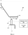
FIG. 2 is a schematic diagram of an example feedback sensing system; -
FIG. 3 is a schematic diagram of the propeller ofFIG. 1 with the feedback device ofFIG. 2 , in accordance with an embodiment; -
FIG. 4A is a schematic bottom view of the feedback device ofFIG. 2 showing the shape of position marker terminations, in accordance with one embodiment; -
FIG. 4B is a schematic bottom view of the feedback device ofFIG. 2 showing the shape of position marker terminations, in accordance with another embodiment; -
FIG. 4C is a schematic bottom view of the feedback device ofFIG. 2 showing the shape of position marker terminations, in accordance with an example outside the wording of the claims; and -
FIG. 5 is a schematic bottom view of the feedback device ofFIG. 2 , showing the shape of position marker terminations, in accordance with yet another embodiment. - It will be noted that throughout the appended drawings, like features are identified by like reference numerals.
-
FIG. 1 depicts agas turbine engine 110 of a type typically provided for use in subsonic flight. Theengine 110 comprises aninlet 112 through which ambient air is propelled, acompressor section 114 for pressurizing the air, acombustor 116 in which the compressed air is mixed with fuel and ignited for generating an annular stream of hot combustion gases, and aturbine section 118 for extracting energy from the combustion gases. - The
turbine section 118 comprises acompressor turbine 120, which drives the compressor assembly and accessories, and at least one power orfree turbine 122, which is independent from thecompressor turbine 120 and rotatingly drives a rotor shaft (also referred to herein as a propeller shaft or an output shaft) 124 about a propeller shaft axis 'A' through a reduction gearbox (RGB) 126. Hot gases may then be evacuated throughexhaust stubs 128. The gas generator of theengine 110 comprises thecompressor section 114, thecombustor 116, and theturbine section 118. - A rotor, in the form of a
propeller 130 through which ambient air is propelled, is hosted in apropeller hub 132. The rotor may, for example, comprise thepropeller 130 of a fixed-wing aircraft, or a main (or tail) rotor of a rotary-wing aircraft such as a helicopter. Thepropeller 130 may comprise a plurality of circumferentially-arranged blades connected to a hub by any suitable means and extending radially therefrom. The blades are also each rotatable about their own radial axes through a plurality of blade angles, which can be changed to achieve modes of operation, such as feather, full reverse, and forward thrust. - With reference to
FIG. 2 , afeedback sensing system 200 for pitch-adjustable blades of bladed rotors of aircraft will now be described. Thesystem 200 may be used for sensing a feedback device (also referred to as a feedback ring or phonic wheel) 204 of an aircraft propeller. It should however be understood that, although thesystem 200 is described and illustrated herein with reference to an aircraft propeller, such as thepropeller 130 ofFIG. 1 , thesystem 200 may apply to other types of rotors, such as those of helicopters. The systems and methods described herein are therefore not limited to being used for aircraft propellers. - In some embodiments, the
system 200 provides for detection and measurement of rotational velocity of one or more rotating elements of theengine 110 and of propeller blade angle on propeller systems, such as thepropeller 130 ofFIG. 1 . Thesystem 200 may interface to existing mechanical interfaces of typical propeller systems to provide a digital detection for electronic determination of the propeller blade angle. It should be noted that although the present disclosure focuses on the use of thesystem 200 and thefeedback device 204 in gas-turbine engines, similar techniques can be applied to other types of engines, including, but not limited to, electric engines and hybrid electric propulsion systems having a propeller driven in a hybrid architecture (series, parallel, or series/parallel) or turboelectric architecture (turboelectric or partial turboelectric). - The
system 200 comprises anannular member 204 and one ormore sensors 212 positioned proximate theannular member 204. Annular member 204 (referred to herein as a feedback device) has a plurality of detectable features (also referred to as position markers or teeth) 202 disposed thereon for detection bysensor 212. In some embodiments, thefeedback device 204 is mounted for rotation withpropeller 130 and to move axially with adjustment of the blade angle of the blades of thepropeller 130, and thesensor 212 is fixedly mounted to a static portion of theengine 110. In other embodiments, thesensor 212 is mounted for rotation withpropeller 130 and to move axially with adjustment of the blade angle of the blades of thepropeller 130, and thefeedback device 204 is fixedly mounted to a static portion of theengine 110. - The
system 200 also includes acontroller 220 communicatively coupled to thesensor 212. Thesensor 212 is configured for producing a sensor signal which is transmitted to or otherwise received by thecontroller 220, for example via adetection unit 222 thereof. The sensor signal can be an electrical signal, digital or analog, or any other suitable type of signal. In some embodiments, thesensor 212 produces a series of signal pulses in response to detecting the presence of aposition marker 202 in a sensing zone of thesensor 212. For example, thesensor 212 is an inductive sensor that operates on detecting changes in magnetic flux, and has a sensing zone which encompasses a circular or rectangular area or volume in front of thesensor 212. When aposition marker 202 is present in the sensing zone, or passes through the zone during rotation of thefeedback device 204, the magnetic flux in the sensing zone is varied by the presence of theposition marker 202, and thesensor 212 can produce a signal pulse, which forms part of the sensor signal. Accordingly, theposition markers 202 may be made of any suitable material (e.g., a ferromagnetic material, Mu-Metal, or the like) which would cause the passage of theposition markers 202 near thesensor 212 to provide a change in magnetic flux within the magnetic field generated by thesensor 212. - In the example illustrated in
FIG. 2 , a side view of a portion offeedback device 204 andsensor 212 is shown. Thesensor 212 is mounted to aflange 214 of a housing of thereduction gearbox 126, so as to be positioned adjacent the plurality ofposition markers 202. In some embodiments, thesensor 212 is secured to thepropeller 130 so as to extend away from theflange 214 and towards theposition markers 202 along a radial direction, identified inFIG. 2 as direction 'R'.Sensor 212 andflange 214 may be fixedly mounted, for example to the housing of thereduction gearbox 126, or to any other static element of theengine 110, as appropriate. - In some embodiments, a
single sensor 212 is mounted in close proximity to thefeedback device 204 and theposition markers 202. In some other embodiments, in order to provide redundancy as well as dual-signal sources at multiple locations, one or more additional sensors, which may be similar to thesensor 212, are provided. For example, anadditional sensor 212 may be mounted in a diametrically opposite relationship, or at any angle, relative to theposition markers 202, which extend away from thefeedback device 204 and towards the sensor(s) 212. In yet another embodiment,several position markers 202 may be spaced equiangularly about the perimeter of thefeedback device 204. Other embodiments may apply. - With additional reference to
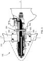
FIG. 3 , in some embodiments thefeedback device 204 is embodied as a circular disk which rotates as part of theengine 110, for example with thepropeller shaft 124 or with thepropeller 130. Thefeedback device 204 comprises opposing faces 3011, 3012 having outer edges 3021, 3022 and defines aroot surface 304 which extends between the opposing faces 3011, 3012 and circumscribes them. Put differently, theroot surface 304 of thefeedback device 204 is the outer periphery of the circular disk which spans between the two opposing faces 3011, 3022 and theroot surface 304 intersects the faces 3011, 3012 at the edges 3021, 3022. In these embodiments, theposition markers 202 can take the form of projections which extend from theroot surface 304. - The
position markers 202 may comprise a plurality of first projections (not shown) arranged along a direction substantially transverse to the opposing faces and substantially equally spaced from one another on theroot surface 304. Theposition markers 202 may also comprise one or more second projections (not shown) each positioned between two adjacent first projections. Each second projection is illustratively oriented along a direction, which is at an angle relative to the direction along which the first projections are arranged. The angle can be any suitable value between 1° and 89°, for example 30°, 45°, 60°, or any other value, as appropriate. It should be noted, however, that in some other embodiments the second projection(s) can be co-oriented with the first projections. It should also be noted that in some embodiments, each second projection can be substituted for a groove or inward projection, as appropriate. In addition, in some embodiments, thefeedback device 204 includes only a single second projection while, in other embodiments, thefeedback device 204 can include more than one second projection. In the latter case, the second projections can be oriented along a common orientation or along one or more different orientations and each second projection can be located at substantially a midpoint between two adjacent first projections or can be located close to a particular one of two adjacent first projections. - In one embodiment, the
position markers 202 are integrally formed with thefeedback device 204 so that thefeedback device 204 may have a unitary construction. In another embodiment, theposition markers 202 are manufactured separately from thefeedback device 204 and attached thereto using any suitable technique, such as welding or the like. - It should also be noted that, although the present disclosure focuses primarily on embodiments in which the
position markers 202 are projections, other embodiments are also considered. Theposition markers 202 may, for example, comprise one or more of protrusions, teeth, walls, voids, recesses, and/or other singularities. For instance, in some embodiments, theposition markers 202 may be embedded in the circular disk portion of thefeedback device 204, such that thefeedback device 204 has a substantially smooth oruniform root surface 304. Aposition marker 202 can then be a portion of thefeedback device 204 which is made of a different material, or to which is applied a layer of a different material. Theposition markers 202 may then be applied to theroot surface 304, for instance as strips of metal or other material for detection by thesensor 212, which can be which can be an inductive sensor capable of sensing changes in magnetic flux (as discussed above) or any other suitable sensor such as a Hall sensor or a variable reluctance sensor as discussed herein above. Still other embodiments are considered. - The signal pulses produced by the
sensor 212, which form part of the electrical signal received by thecontrol system 220, can be used to determine various operating parameters of theengine 110 and thepropeller 130. The regular spacing of the first projections can, for example, be used to determine a speed of rotation of thefeedback device 204. In addition, the second projection(s) can be detected by thesensor 212 to determine a blade angle of thepropeller 130. - With continued reference to
FIG. 3 , thefeedback device 204 is supported for rotation with thepropeller 130, which rotates about the longitudinal axis 'A'. Thefeedback device 204 is also supported for longitudinal sliding movement along the axis A, e.g. by support members, such as a series of circumferentially spacedfeedback rods 306 that extend along the axis A. Acompression spring 308 surrounds an end portion of eachrod 306. - As depicted in
FIG. 3 , thepropeller 130 comprises a plurality of angularly arrangedblades 310, each of which is rotatable about a radially-extending axis 'R' through a plurality of adjustable blade angles, the blade angle being the angle between the chord line (i.e. a line drawn between the leading and trailing edges of the blade) of the propeller blade section and a plane perpendicular to the axis of propeller rotation. In some embodiments, thepropeller 130 is a reversing propeller, capable of operating in a variety of modes of operation, including feather, full reverse, and forward thrust. Depending on the mode of operation, the blade angle may be positive or negative: the feather and forward thrust modes are associated with positive blade angles, and the full reverse mode is associated with negative blade angles. - Referring now to
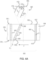
FIG. 4A , thefeedback device 204 illustratively comprisesposition markers 202, which, in one embodiment, can take the form of projections which extend from theroot surface 304. As thefeedback device 204 rotates, varying portions thereof enter, pass through, and then exit the sensing zone of thesensor 212. From the perspective of thesensor 212, thefeedback device 204 moves axially along axis A and rotates about direction 'F'. However, as thesensor 212 moves towards and is positioned adjacent to the edges 3021, 3022 of thefeedback device 204 as a result of movement of thefeedback device 204, the markers' magnetic centerline is shifted. As will be discussed further below, this results in a so-called "edge-effect" that leads to an increase in reading error (also referred to herein as beta error) in the measured position of thefeedback device 204 at the edges 3021, 3022. In order to permit thesensor 212 to accurately detect the passage of theposition markers 202 without any (or with reduced) edge-related effects, it is proposed herein to modify the geometry of theposition markers 202, as will be discussed further below. - In one embodiment illustrated in
FIG. 4A , theposition markers 202 include a plurality of projections 402 (also referred to herein as 'straight' projections) which are arranged along a direction 'D', which is substantially transverse to the opposing edges 3021, 3022. Although only twoprojections 402 are illustrated inFIG. 4A , it should be understood that any suitable number ofprojections 402 may be present across the whole of theroot surface 304. Theprojections 402 can be substantially equally spaced from one another on theroot surface 304. In addition, theprojections 402 are of substantially a common shape and size, for example having a common volumetric size. - The
feedback device 204 also includes at least one supplementary (or 'angled')projection 404 which is positioned between two adjacent ones of theprojections 402. In the embodiment depicted inFIG. 4A , theprojection 404 is oriented along a direction 'E', which is at an angle relative to direction 'D'. The angle between directions 'D' and 'E' can be any suitable value between 1° and 89°, for example 30°, 45°, 60°, or any other value, as appropriate. In some embodiments, thefeedback device 204 includes only a singlesupplementary projection 404. In other embodiments, thefeedback device 204 can include two, three, four, or moresupplementary projections 404. In embodiments in which thefeedback device 204 includes more than onesupplementary projection 404, the supplementary projections can all be oriented along a common orientation, for instance direction 'E', or can be oriented along one or more different orientations. Theprojection 404 can be located at substantially a midpoint between twoadjacent projections 402, or, as shown inFIG. 4A , can be located close to a particular one of twoadjacent projections 402. - As shown in
FIG. 4A , eachprojection projection 402 and along longitudinal direction 'E' for projection 404), from a first axial end ortermination 406 to a second termination 408 (opposite the first termination 406), such that eachtermination feedback device 204. Eachprojection projection termination edge 412. - In the embodiment of
FIG. 4A , for eachprojection 402, theedge 412 of eachtermination feedback device 204 thetermination projection 402 is symmetrical about its geometrical centerline 'C' from onetermination edges 412 of theangled projection 404 were to also be substantially parallel to the edges 3021, 3022, this would result in theangled projection 404 being asymmetrical about its geometrical centerline 'C' adjacent the edges 3021, 3022. Indeed, at eachtermination termination 406 having anedge 412 substantially parallel with the feedback device's edge 3021, the portion of thetermination 406 delimited by the centerline C, theedge 412, and the second longitudinal edge 4102 (obtuse angle side) would have a greater volumetric size than the portion of thetermination 406 defined by the centerline C, theedge 412, and the first longitudinal edge 4101 (acute angle side). This asymmetric distribution of material on theangled projection 404 would then lead to a distortion of the angled projection's magnetic centerline (away from the geometric centerline C) due to magnetic flux asymmetry. As thesensor 212 approaches the edges 3021, 3022 of thefeedback device 204, this asymmetry would result in an increase in the time interval between the passage of thestraight projection 402 and the passage of theangled projection 404, as detected by thesensor 212. This would in turn increase the reading error (or edge-effect) and lead to inaccurate measurement of the position of the feedback device 204 (since the position of thefeedback device 204 is determined by the relative timing between thestraight projections 402 and the angled projection 404), and thus to inaccurate blade pitch (or beta) angle measurement by thesensor 212. - In order to reduce any edge-related effects, it is proposed herein to modify the geometry of the
terminations angled projection 404 such that theterminations sensor 212 approaches the edges 3021, 3022 of thefeedback device 204, theangled projection 404 appears magnetically symmetrical about the geometric centerline C, thus improving the accuracy of thebeta measurement system 200. - For this purpose, in one embodiment, the
terminations angled projection 404 are shaped so as to be non-flush with the plane defined by a corresponding feedback device face 3011, 3012 thetermination FIG. 4A ,FIG. 4B , andFIG. 4C . In other words, for eachangled projection 404, theedge 412 of eachtermination termination terminations angled projection 404 remains symmetrical about the centerline C throughout its length, i.e. from onetermination - In the embodiment shown in
FIG. 4A , material is removed from theterminations angled projection 404 to achieve beveled chamferedterminations edge 412 of eachtermination termination termination 406 inFIG. 4A ) is profiled such that itsedge 412 comprises afirst section 4121 that is substantially aligned with the feedback device's edge 302, and asecond section 4122 that is at an angle relative to thefirst edge section 412, and to the edge 3021. The first andsecond edge sections second edge section 4122 and the feedback device edge 302, is set such that thetermination 406 is symmetrical about the centerline C. In particular, thefirst edge section 412, forms a first acute angle θ1 with the centerline C and thesecond edge section 4122 forms a second acute angle θ2 with the centerline C, the first angle θ1 substantially equal to the second angle θ2. - Referring now to
FIG. 4B in addition toFIG. 4A , in accordance with another embodiment, in addition to profiling theterminations angled projection 404 in the manner described above with reference toFIG. 4A , thefeedback device 204 is also beveled adjacent the angled projection'sterminations feedback device 204 adjacent thesecond edge section 4122, thereby creating notches as in 414 along the edges 3021, 3022. In one embodiment, provision of the notches as in 414 may further decrease reading error by further reducing the asymmetric distribution of material on theangled projection 404. - Referring now
FIG. 4C , which is outside the wording of the claims, although theedges 412 are illustrated and described herein as being straight, it should be understood that theterminations edges 412 is illustratively selected to ensure that theangled projection 404 remains symmetrical about the centerline C at theterminations edges 412 may allow to simplify manufacture and inspection of the feedback device 204 (e.g., by providing allmarkers - Referring now to
FIG. 5 , it should also be understood that, in another embodiment, theangled projection 404 may be made symmetrical about the centerline C with theterminations termination terminations material 416 on the acute angle side of thetermination 406, 408 (without extending theterminations FIGs. 4A ,4B , and4C , where material is removed on the obtuse angle side of theterminations termination 406 is modified to add the extrusion ofmaterial 416 at the longitudinal edge 4101, thereby increasing the volumetric size of the portion of thetermination 406 provided at acute angle side. The amount of extrusion ofmaterial 416 to be added is such that the volumetric size of thetermination 406 at the acute angle side is substantially similar to the volumetric size of the termination at the obtuse angle side, thereby achieving symmetry about the centerline C. In one embodiment, the extrusion ofmaterial 416 is integral with thefeedback device 204, whereby the extrusion is machined from solid. In another embodiment, the extrusion ofmaterial 416 is added to thefeedback device 204 by welding. It should however be understood that any suitable manufacturing method including, but not limited to, additive manufacturing, casting, forging, extrusion, powder metallurgy, blanking, broaching, milling, and grinding, may apply. - It should be understood that, although
FIGs. 4A to 5 only detail the configuration of the termination 406 (for clarity purposes), thetermination 408 is shaped similarly totermination 406 in each embodiment. It should also be understood that the shape of theterminations feedback device 204. Additional factors including, but not limited to, the amount of beta error, the available space according to clearances and tolerance stackup of the feedback system, and the accuracy required by the feedback system, may also come into play. - From the above description, it can be seen that, in one embodiment, the
feedback device 204 may be configured to allow for thesensor 212 to be positioned near or at the edges 3021, 3022 of thefeedback device 204 while accurately detecting the passage of theposition markers 202, thereby mitigating any edge-related effects that may influence thesensor 212. - The above description is meant to be exemplary only, and one skilled in the art will recognize that changes may be made to the embodiments described without departing from the scope of the invention disclosed. Still other modifications which fall within the scope of the present invention will be apparent to those skilled in the art, in light of a review of this disclosure.
- The scope of the following claims should not be limited by the embodiments set forth in the examples, but should be given the broadest reasonable interpretation consistent with the description as a whole.
Claims (14)
- A blade angle feedback assembly (200) for an aircraft-bladed rotor (130), the rotor (130) rotatable about a longitudinal axis (A) and having an adjustable blade pitch angle, the assembly (200) comprising:a feedback device (204) having a root surface (304) having a first edge (3021);a plurality of first position markers (402) disposed on the root surface (304) and oriented substantially parallel to the longitudinal axis (A), the plurality of first position markers (402) circumferentially spaced from one another;at least one second position marker (404) disposed on the root surface (304) and positioned between two adjacent first position markers (402) at an angle thereto, the at least one second position marker (404) having an end (406) positioned adjacent to the first edge (3021) and non-flush therewith; andat least one sensor (212) configured to be mounted adjacent the feedback device (204), wherein one of the feedback device (204) and the at least one sensor (212) is configured to be coupled to rotate with the rotor (130), and the at least one sensor (212) is configured to detect a relative passage of the plurality of first position markers (402) and the at least one second position marker (404) as the one of the feedback device (204) and the at least one sensor (212) configured to be coupled to rotate with the rotor (130) rotates about the longitudinal axis (A),wherein the end (406) of the at least one second position marker (404) is beveled at an angle with respect to the first edge (3021).
- The feedback assembly of claim 1, wherein the end (406) of the at least one second position marker (404) comprises a second edge (412), the second edge (412) having a first edge section (4121) substantially aligned with the first edge (3021) and a second edge section (4122) angled relative to the first edge (3021).
- The feedback assembly of claim 2, wherein the first edge section (4121) and the second edge section (4122) connect at a geometric centerline (C) of the at least one second position marker (404), the first edge section (4121) forming a first acute angle (θ1) with the centerline (C) and the second section (4122) forming a second acute angle (θ2) with the centerline (C), the first angle (θ1) substantially equal to the second angle (θ2).
- The feedback assembly of claim 2 or 3, wherein a notch (414) is formed in the root surface (304) adjacent the second edge section (4122).
- An aircraft-bladed rotor system, comprising:a rotor (130) rotatable by a shaft (124) about a longitudinal axis (A), the rotor (130) having blades (310) with adjustable blade pitch angle; anda feedback device (204) coupled to rotate with the rotor (130) or fixed relative to the rotor (130), the feedback device (204) having:at least one second position marker (404) disposed on the root surface (304) and positioned between two adjacent first position markers (402) at an angle thereto, the at least one second position marker (404) having an end (406) positioned adjacent to the first edge (3021) and non-flush therewith, wherein the end (406) of the at least one second position marker (404) is beveled at an angle with respect to the first edge (3021).a root surface (304) having a first edge (3021);a plurality of first position markers (402) disposed on the root surface (304) and oriented substantially parallel to the longitudinal axis (A), the plurality of first position markers (402) circumferentially spaced from one another; and
- The system of claim 5, wherein the end (406) of the at least one second position marker (404) comprises a second edge (412), the second edge (412) having a first edge section (4121) substantially aligned with the first edge (3021) and a second edge section (4122) angled relative to the first edge (3021).
- The system of claim 6, wherein the first edge section (4121) and the second edge section (4122) connect at a geometric centerline (C) of the at least one second position marker (404), the first edge section (4121) forming a first acute angle (θ1) with the centerline (C) and the second edge section (4122) forming a second acute angle (θ2) with the centerline (C), the first angle (θ1) substantially equal to the second angle (θ2).
- The system of claim 6 or 7, wherein a notch (414) is formed in the root surface (304) adjacent the second edge section (4122).
- An aircraft-bladed rotor system, comprising:a rotor (130) rotatable by a shaft (124) about a longitudinal axis (A), the rotor (130) having blades (310) with adjustable blade pitch angle; anda feedback device (204) coupled to rotate with the rotor (130) or fixed relative to the rotor (130), the feedback device (204) having:a root surface (304) having a first edge (302,);a plurality of first position markers (402) extending from the root surface (304) and oriented substantially parallel to the longitudinal axis (A), the plurality of first position markers (402) circumferentially spaced from one another; andat least one second position marker (404) extending from the root surface (304) and positioned between two adjacent first position markers (402) at an angle thereto, the at least one second position marker (404) having an end (406) positioned adjacent to the first edge (3021) and substantially flush therewith, and having a geometric centerline (C) forming an acute angle with the first edge (3021) on one side of the geometric centerline (C) and an obtuse angle with the first edge (3021) on the other side of the geometric centerline (C), an extrusion of material (416) provided at the end (406) to increase the volumetric size of the end (406) at the acute angle side.
- The system of any of claims 5 to 9, wherein the feedback device (204) is coupled to rotate with the rotor (130), and further comprising at least one sensor (212) configured to be mounted adjacent the feedback device (204) and configured to detect a passage of the plurality of first position markers (402) and the at least one second position marker (404) as the feedback device (204) rotates about the longitudinal axis (A).
- The system of any of claims 5 to 9, wherein the feedback device (204) is configured to be fixed relative to the rotor (130), and further comprising at least one sensor (212) mounted adjacent the feedback device (204), wherein the at least one sensor (212) is coupled to rotate with the rotor (130), and the at least one sensor (212) is configured to detect a relative passage of the plurality of first position markers (402) and the at least one second position marker (404) as the at least one sensor (212) rotates about the longitudinal axis (A).
- A gas turbine engine (110) comprising the system of any of claims 5 to 9, further comprising at least one sensor (212) mounted adjacent the feedback device (204), wherein the feedback device (204) is coupled to rotate with the rotor (130) and to move axially with adjustment of the blade pitch angle of the blades (310), and the at least one sensor (212) is fixedly mounted to a static portion of the engine (110), and the at least one sensor (212) is configured to detect a passage of the plurality of first position markers (402) and the at least one second position marker (404) as the feedback device (204) rotates about the longitudinal axis (A).
- An gas turbine engine (110) comprising the system of any of claims 5 to 9, further comprising at least one sensor (212) mounted adjacent the feedback device (204), wherein the at least one sensor (212) is coupled to rotate with the rotor (130) and to move axially with adjustment of the blade pitch angle of the blades (310), and the feedback device (204) is fixedly mounted to a static portion of the engine (110), and the at least one sensor (212) is configured to detect a relative passage of the plurality of first position markers (402) and the at least one second position marker (404) as the at least one sensor (212) rotates about the longitudinal axis (A).
- A blade angle feedback assembly (200) for an aircraft-bladed rotor (130), the rotor (130) rotatable about a longitudinal axis (A) and having an adjustable blade pitch angle, the assembly (200) comprising:a feedback device (204) having a root surface (304) having a first edge (3021);a plurality of first position markers (402) extending from the root surface (304) and oriented substantially parallel to the longitudinal axis (A), the plurality of first position markers (402) circumferentially spaced from one another;at least one second position marker (404) extending from the root surface (304) and positioned between two adjacent first position markers (402) at an angle thereto, the at least one second position marker (404) having an end (406) positioned adjacent to the first edge (3021) and substantially flush therewith, and having a geometric centerline (C) forming an acute angle with the first edge (3021) on one side of the geometric centerline (C) and an obtuse angle with the first edge (3021) on the other side of the geometric centerline (C), an extrusion of material (416) provided at the end (406) to increase the volumetric size of the end (406) at the acute angle side; andat least one sensor (212) configured to be mounted adjacent the feedback device (204), wherein one of the feedback device (204) and the at least one sensor (212) is configured to be coupled to rotate with the rotor (130), and the at least one sensor (212) is configured to detect a passage of the plurality of first position markers (402) and the at least one second position marker (404) as the one of the feedback device (204) and the at least one sensor (212) configured to be coupled to rotate with the rotor (130) rotates about the longitudinal axis (A).
Applications Claiming Priority (2)
| Application Number | Priority Date | Filing Date | Title |
|---|---|---|---|
| US201962831252P | 2019-04-09 | 2019-04-09 | |
| US16/703,394 US11643187B2 (en) | 2019-04-09 | 2019-12-04 | Blade angle position feedback system with profiled marker terminations |
Publications (2)
| Publication Number | Publication Date |
|---|---|
| EP3722204A1 EP3722204A1 (en) | 2020-10-14 |
| EP3722204B1 true EP3722204B1 (en) | 2023-08-30 |
Family
ID=70285532
Family Applications (1)
| Application Number | Title | Priority Date | Filing Date |
|---|---|---|---|
| EP20169093.0A Active EP3722204B1 (en) | 2019-04-09 | 2020-04-09 | Blade angle position feedback system with profiled marker terminations |
Country Status (3)
| Country | Link |
|---|---|
| US (1) | US11643187B2 (en) |
| EP (1) | EP3722204B1 (en) |
| PL (1) | PL3722204T3 (en) |
Families Citing this family (1)
| Publication number | Priority date | Publication date | Assignee | Title |
|---|---|---|---|---|
| CN112697438B (en) * | 2020-12-23 | 2023-04-14 | 南京航空航天大学 | Turboprop engine pitch-phase angle-rotating speed measuring device and method based on tone wheel |
Family Cites Families (8)
| Publication number | Priority date | Publication date | Assignee | Title |
|---|---|---|---|---|
| US2806402A (en) * | 1954-10-04 | 1957-09-17 | Gen Motors Corp | Propeller blade angle indicating device |
| GB2221306A (en) | 1988-07-29 | 1990-01-31 | Dowty Rotol Ltd | Assembly for determining the longitudinal displacement of a rotating shaft |
| KR20140137738A (en) | 2013-05-23 | 2014-12-03 | 삼성전자주식회사 | Image display method, image display apparatus and recordable media |
| US9821901B2 (en) | 2013-11-21 | 2017-11-21 | Pratt & Whitney Canada Corp. | System and method for electronic propeller blade angle position feedback |
| US10486827B2 (en) | 2016-08-17 | 2019-11-26 | Pratt & Whitney Canada Corp. | Apparatus and methods for aircraft propeller control |
| US10889367B2 (en) | 2017-04-24 | 2021-01-12 | Pratt & Whitney Canada Corp. | Feedback system for pitch-adjustable blades of aircraft bladed rotor |
| US20180320601A1 (en) | 2017-05-04 | 2018-11-08 | Rolls-Royce Corporation | Turbine assembly with auxiliary wheel |
| US11286038B2 (en) * | 2019-09-03 | 2022-03-29 | Pratt & Whitney Canada Corp. | Pitch control assembly for an aircraft-bladed rotor |
-
2019
- 2019-12-04 US US16/703,394 patent/US11643187B2/en active Active
-
2020
- 2020-04-09 PL PL20169093.0T patent/PL3722204T3/en unknown
- 2020-04-09 EP EP20169093.0A patent/EP3722204B1/en active Active
Also Published As
| Publication number | Publication date |
|---|---|
| PL3722204T3 (en) | 2024-02-19 |
| US20200324876A1 (en) | 2020-10-15 |
| EP3722204A1 (en) | 2020-10-14 |
| US11643187B2 (en) | 2023-05-09 |
Similar Documents
| Publication | Publication Date | Title |
|---|---|---|
| EP3730902B1 (en) | Blade angle position feedback system with offset sensors | |
| EP3712057B1 (en) | Blade angle position feedback system with extended markers | |
| EP3831711B1 (en) | Blade angle feedback device with variable magnetic permeability | |
| US11685514B2 (en) | Pitch control assembly for an aircraft-bladed rotor | |
| US11623735B2 (en) | Blade angle position feedback system with magnetic shield | |
| EP3744630B1 (en) | Feedback device with differing magnetic permeability zones | |
| EP3722204B1 (en) | Blade angle position feedback system with profiled marker terminations | |
| CA3077916A1 (en) | Blade angle position feedback system with profiled marker terminations | |
| EP3838745B1 (en) | System and method for determining an axial position of a feedback device | |
| EP3744629B1 (en) | Feedback device with non-axially aligned position markers | |
| CA3080300A1 (en) | Feedback device with differing magnetic permeability zones |
Legal Events
| Date | Code | Title | Description |
|---|---|---|---|
| PUAI | Public reference made under article 153(3) epc to a published international application that has entered the european phase |
Free format text: ORIGINAL CODE: 0009012 |
|
| STAA | Information on the status of an ep patent application or granted ep patent |
Free format text: STATUS: THE APPLICATION HAS BEEN PUBLISHED |
|
| AK | Designated contracting states |
Kind code of ref document: A1 Designated state(s): AL AT BE BG CH CY CZ DE DK EE ES FI FR GB GR HR HU IE IS IT LI LT LU LV MC MK MT NL NO PL PT RO RS SE SI SK SM TR |
|
| AX | Request for extension of the european patent |
Extension state: BA ME |
|
| STAA | Information on the status of an ep patent application or granted ep patent |
Free format text: STATUS: REQUEST FOR EXAMINATION WAS MADE |
|
| 17P | Request for examination filed |
Effective date: 20210414 |
|
| RBV | Designated contracting states (corrected) |
Designated state(s): AL AT BE BG CH CY CZ DE DK EE ES FI FR GB GR HR HU IE IS IT LI LT LU LV MC MK MT NL NO PL PT RO RS SE SI SK SM TR |
|
| STAA | Information on the status of an ep patent application or granted ep patent |
Free format text: STATUS: EXAMINATION IS IN PROGRESS |
|
| 17Q | First examination report despatched |
Effective date: 20211020 |
|
| GRAP | Despatch of communication of intention to grant a patent |
Free format text: ORIGINAL CODE: EPIDOSNIGR1 |
|
| STAA | Information on the status of an ep patent application or granted ep patent |
Free format text: STATUS: GRANT OF PATENT IS INTENDED |
|
| INTG | Intention to grant announced |
Effective date: 20230315 |
|
| GRAS | Grant fee paid |
Free format text: ORIGINAL CODE: EPIDOSNIGR3 |
|
| GRAA | (expected) grant |
Free format text: ORIGINAL CODE: 0009210 |
|
| STAA | Information on the status of an ep patent application or granted ep patent |
Free format text: STATUS: THE PATENT HAS BEEN GRANTED |
|
| AK | Designated contracting states |
Kind code of ref document: B1 Designated state(s): AL AT BE BG CH CY CZ DE DK EE ES FI FR GB GR HR HU IE IS IT LI LT LU LV MC MK MT NL NO PL PT RO RS SE SI SK SM TR |
|
| REG | Reference to a national code |
Ref country code: GB Ref legal event code: FG4D |
|
| REG | Reference to a national code |
Ref country code: CH Ref legal event code: EP |
|
| REG | Reference to a national code |
Ref country code: DE Ref legal event code: R096 Ref document number: 602020016501 Country of ref document: DE |
|
| REG | Reference to a national code |
Ref country code: IE Ref legal event code: FG4D |
|
| REG | Reference to a national code |
Ref country code: LT Ref legal event code: MG9D |
|
| REG | Reference to a national code |
Ref country code: NL Ref legal event code: MP Effective date: 20230830 |
|
| REG | Reference to a national code |
Ref country code: AT Ref legal event code: MK05 Ref document number: 1605131 Country of ref document: AT Kind code of ref document: T Effective date: 20230830 |
|
| PG25 | Lapsed in a contracting state [announced via postgrant information from national office to epo] |
Ref country code: GR Free format text: LAPSE BECAUSE OF FAILURE TO SUBMIT A TRANSLATION OF THE DESCRIPTION OR TO PAY THE FEE WITHIN THE PRESCRIBED TIME-LIMIT Effective date: 20231201 |
|
| PG25 | Lapsed in a contracting state [announced via postgrant information from national office to epo] |
Ref country code: IS Free format text: LAPSE BECAUSE OF FAILURE TO SUBMIT A TRANSLATION OF THE DESCRIPTION OR TO PAY THE FEE WITHIN THE PRESCRIBED TIME-LIMIT Effective date: 20231230 |
|
| PG25 | Lapsed in a contracting state [announced via postgrant information from national office to epo] |
Ref country code: SE Free format text: LAPSE BECAUSE OF FAILURE TO SUBMIT A TRANSLATION OF THE DESCRIPTION OR TO PAY THE FEE WITHIN THE PRESCRIBED TIME-LIMIT Effective date: 20230830 Ref country code: RS Free format text: LAPSE BECAUSE OF FAILURE TO SUBMIT A TRANSLATION OF THE DESCRIPTION OR TO PAY THE FEE WITHIN THE PRESCRIBED TIME-LIMIT Effective date: 20230830 Ref country code: NO Free format text: LAPSE BECAUSE OF FAILURE TO SUBMIT A TRANSLATION OF THE DESCRIPTION OR TO PAY THE FEE WITHIN THE PRESCRIBED TIME-LIMIT Effective date: 20231130 Ref country code: LV Free format text: LAPSE BECAUSE OF FAILURE TO SUBMIT A TRANSLATION OF THE DESCRIPTION OR TO PAY THE FEE WITHIN THE PRESCRIBED TIME-LIMIT Effective date: 20230830 Ref country code: LT Free format text: LAPSE BECAUSE OF FAILURE TO SUBMIT A TRANSLATION OF THE DESCRIPTION OR TO PAY THE FEE WITHIN THE PRESCRIBED TIME-LIMIT Effective date: 20230830 Ref country code: IS Free format text: LAPSE BECAUSE OF FAILURE TO SUBMIT A TRANSLATION OF THE DESCRIPTION OR TO PAY THE FEE WITHIN THE PRESCRIBED TIME-LIMIT Effective date: 20231230 Ref country code: HR Free format text: LAPSE BECAUSE OF FAILURE TO SUBMIT A TRANSLATION OF THE DESCRIPTION OR TO PAY THE FEE WITHIN THE PRESCRIBED TIME-LIMIT Effective date: 20230830 Ref country code: GR Free format text: LAPSE BECAUSE OF FAILURE TO SUBMIT A TRANSLATION OF THE DESCRIPTION OR TO PAY THE FEE WITHIN THE PRESCRIBED TIME-LIMIT Effective date: 20231201 Ref country code: FI Free format text: LAPSE BECAUSE OF FAILURE TO SUBMIT A TRANSLATION OF THE DESCRIPTION OR TO PAY THE FEE WITHIN THE PRESCRIBED TIME-LIMIT Effective date: 20230830 Ref country code: AT Free format text: LAPSE BECAUSE OF FAILURE TO SUBMIT A TRANSLATION OF THE DESCRIPTION OR TO PAY THE FEE WITHIN THE PRESCRIBED TIME-LIMIT Effective date: 20230830 |
|
| PG25 | Lapsed in a contracting state [announced via postgrant information from national office to epo] |
Ref country code: NL Free format text: LAPSE BECAUSE OF FAILURE TO SUBMIT A TRANSLATION OF THE DESCRIPTION OR TO PAY THE FEE WITHIN THE PRESCRIBED TIME-LIMIT Effective date: 20230830 |