EP3722204B1 - Blattwinkelpositionrückmeldesystem mit profilierten markierungsenden - Google Patents
Blattwinkelpositionrückmeldesystem mit profilierten markierungsenden Download PDFInfo
- Publication number
- EP3722204B1 EP3722204B1 EP20169093.0A EP20169093A EP3722204B1 EP 3722204 B1 EP3722204 B1 EP 3722204B1 EP 20169093 A EP20169093 A EP 20169093A EP 3722204 B1 EP3722204 B1 EP 3722204B1
- Authority
- EP
- European Patent Office
- Prior art keywords
- edge
- feedback device
- sensor
- rotor
- angle
- Prior art date
- Legal status (The legal status is an assumption and is not a legal conclusion. Google has not performed a legal analysis and makes no representation as to the accuracy of the status listed.)
- Active
Links
- 239000003550 marker Substances 0.000 title claims description 29
- 239000000463 material Substances 0.000 claims description 19
- 230000001154 acute effect Effects 0.000 claims description 15
- 238000001125 extrusion Methods 0.000 claims description 9
- 230000003068 static effect Effects 0.000 claims description 5
- 230000005291 magnetic effect Effects 0.000 description 8
- 238000001514 detection method Methods 0.000 description 5
- 230000004907 flux Effects 0.000 description 5
- 239000007789 gas Substances 0.000 description 4
- 238000004519 manufacturing process Methods 0.000 description 4
- 238000005259 measurement Methods 0.000 description 4
- 238000000034 method Methods 0.000 description 4
- 230000002441 reversible effect Effects 0.000 description 4
- 238000013459 approach Methods 0.000 description 3
- 230000000694 effects Effects 0.000 description 3
- 210000003746 feather Anatomy 0.000 description 3
- 230000009467 reduction Effects 0.000 description 3
- 239000003570 air Substances 0.000 description 2
- 239000012080 ambient air Substances 0.000 description 2
- 239000000567 combustion gas Substances 0.000 description 2
- 238000010586 diagram Methods 0.000 description 2
- 238000009826 distribution Methods 0.000 description 2
- 230000001939 inductive effect Effects 0.000 description 2
- 238000003801 milling Methods 0.000 description 2
- 238000003466 welding Methods 0.000 description 2
- 239000000654 additive Substances 0.000 description 1
- 230000000996 additive effect Effects 0.000 description 1
- 238000005266 casting Methods 0.000 description 1
- 230000008859 change Effects 0.000 description 1
- 230000006835 compression Effects 0.000 description 1
- 238000007906 compression Methods 0.000 description 1
- 238000010276 construction Methods 0.000 description 1
- 230000001419 dependent effect Effects 0.000 description 1
- 239000003302 ferromagnetic material Substances 0.000 description 1
- 238000005242 forging Methods 0.000 description 1
- 239000000446 fuel Substances 0.000 description 1
- 238000000227 grinding Methods 0.000 description 1
- 238000007689 inspection Methods 0.000 description 1
- 239000002184 metal Substances 0.000 description 1
- 230000000116 mitigating effect Effects 0.000 description 1
- 238000012986 modification Methods 0.000 description 1
- 230000004048 modification Effects 0.000 description 1
- 229910000595 mu-metal Inorganic materials 0.000 description 1
- 238000004663 powder metallurgy Methods 0.000 description 1
- 230000004044 response Effects 0.000 description 1
- 238000012552 review Methods 0.000 description 1
- 239000007787 solid Substances 0.000 description 1
Images


Classifications
-
- B—PERFORMING OPERATIONS; TRANSPORTING
- B64—AIRCRAFT; AVIATION; COSMONAUTICS
- B64C—AEROPLANES; HELICOPTERS
- B64C11/00—Propellers, e.g. of ducted type; Features common to propellers and rotors for rotorcraft
- B64C11/30—Blade pitch-changing mechanisms
- B64C11/301—Blade pitch-changing mechanisms characterised by blade position indicating means
-
- B—PERFORMING OPERATIONS; TRANSPORTING
- B64—AIRCRAFT; AVIATION; COSMONAUTICS
- B64D—EQUIPMENT FOR FITTING IN OR TO AIRCRAFT; FLIGHT SUITS; PARACHUTES; ARRANGEMENTS OR MOUNTING OF POWER PLANTS OR PROPULSION TRANSMISSIONS IN AIRCRAFT
- B64D31/00—Power plant control; Arrangement thereof
-
- G—PHYSICS
- G01—MEASURING; TESTING
- G01B—MEASURING LENGTH, THICKNESS OR SIMILAR LINEAR DIMENSIONS; MEASURING ANGLES; MEASURING AREAS; MEASURING IRREGULARITIES OF SURFACES OR CONTOURS
- G01B7/00—Measuring arrangements characterised by the use of electric or magnetic techniques
- G01B7/30—Measuring arrangements characterised by the use of electric or magnetic techniques for measuring angles or tapers; for testing the alignment of axes
-
- G—PHYSICS
- G01—MEASURING; TESTING
- G01D—MEASURING NOT SPECIALLY ADAPTED FOR A SPECIFIC VARIABLE; ARRANGEMENTS FOR MEASURING TWO OR MORE VARIABLES NOT COVERED IN A SINGLE OTHER SUBCLASS; TARIFF METERING APPARATUS; MEASURING OR TESTING NOT OTHERWISE PROVIDED FOR
- G01D5/00—Mechanical means for transferring the output of a sensing member; Means for converting the output of a sensing member to another variable where the form or nature of the sensing member does not constrain the means for converting; Transducers not specially adapted for a specific variable
- G01D5/12—Mechanical means for transferring the output of a sensing member; Means for converting the output of a sensing member to another variable where the form or nature of the sensing member does not constrain the means for converting; Transducers not specially adapted for a specific variable using electric or magnetic means
- G01D5/14—Mechanical means for transferring the output of a sensing member; Means for converting the output of a sensing member to another variable where the form or nature of the sensing member does not constrain the means for converting; Transducers not specially adapted for a specific variable using electric or magnetic means influencing the magnitude of a current or voltage
- G01D5/20—Mechanical means for transferring the output of a sensing member; Means for converting the output of a sensing member to another variable where the form or nature of the sensing member does not constrain the means for converting; Transducers not specially adapted for a specific variable using electric or magnetic means influencing the magnitude of a current or voltage by varying inductance, e.g. by a movable armature
Landscapes
- Engineering & Computer Science (AREA)
- Aviation & Aerospace Engineering (AREA)
- Physics & Mathematics (AREA)
- General Physics & Mathematics (AREA)
- Transmission And Conversion Of Sensor Element Output (AREA)
Claims (14)
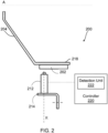
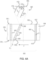
- Blattwinkelrückkopplungsbaugruppe (200) für einen Rotor (130) mit Luftfahrzeugblättern, wobei der Rotor (130) um eine Längsachse (A) drehbar ist und einen einstellbaren Blattanstellwinkel aufweist, wobei die Baugruppe (200) Folgendes umfasst:eine Rückkopplungsvorrichtung (204), die eine Fußfläche (304) aufweist, die eine erste Kante (3021) aufweist;eine Vielzahl von ersten Positionsmarkierungen (402), die auf der Fußfläche (304) angeordnet ist und im Wesentlichen parallel zu der Längsachse (A) ausgerichtet ist, wobei die Vielzahl von ersten Positionsmarkierungen (402) in Umfangsrichtung voneinander beabstandet ist;mindestens eine zweite Positionsmarkierung (404), die auf der Fußfläche (304) angeordnet und zwischen zwei benachbarten ersten Positionsmarkierungen (402) in einem Winkel dazu positioniert ist, wobei die mindestens eine zweite Positionsmarkierung (404) ein Ende (406) aufweist, das benachbart an der ersten Kante (3021) positioniert und nicht bündig damit ist; undmindestens einen Sensor (212), der dazu konfiguriert ist, benachbart an die Rückkopplungsvorrichtung (204) montiert zu werden, wobei eines der Rückkopplungsvorrichtung (204) und des mindestens einen Sensors (212) dazu konfiguriert ist, zum Drehen mit dem Rotor (130) gekoppelt zu sein, und der mindestens eine Sensor (212) dazu konfiguriert ist, einen relativen Durchgang der Vielzahl von ersten Positionsmarkierungen (402) und der mindestens einen zweiten Positionsmarkierung (404) zu erkennen, wenn sich eines der Rückkopplungsvorrichtung (204) und des mindestens einen Sensors (212), der dazu konfiguriert ist, zum Drehen mit dem Rotor (130) gekoppelt zu sein, um die Längsachse (A) dreht,wobei das Ende (406) der mindestens einen zweiten Positionsmarkierung (404) in einem Winkel in Bezug auf die erste Kante (3021) abgeschrägt ist.
- Rückkopplungsbaugruppe nach Anspruch 1, wobei das Ende (406) der mindestens einen zweiten Positionsmarkierung (404) eine zweite Kante (412) umfasst, wobei die zweite Kante (412) einen ersten Kantenabschnitt (4121), der im Wesentlichen mit der ersten Kante (3021) ausgerichtet ist, und einen zweiten Kantenabschnitt (4122) aufweist, der relativ zu der ersten Kante (3021) abgewinkelt ist.
- Rückkopplungsbaugruppe nach Anspruch 2, wobei sich der erste Kantenabschnitt (4121) und der zweite Kantenabschnitt (4122) an einer geometrischen Mittellinie (C) der mindestens einen zweiten Positionsmarkierung (404) verbinden, wobei der ersten Kantenabschnitt (4121) einen ersten spitzen Winkel (θ1) mit der Mittellinie (C) ausbildet und der zweite Abschnitt (4122) einen zweiten spitzen Winkel (θ2) mit der Mittellinie (C) ausbildet, wobei der erste Winkel (θ1) im Wesentlichen gleich dem zweiten Winkel (θ2) ist.
- Rückkopplungsbaugruppe nach Anspruch 2 oder 3, wobei eine Kerbe (414) in der Fußfläche (304) benachbart an dem zweiten Kantenabschnitt (4122) ausgebildet ist.
- Rotorsystem mit Luftfahrzeugblättern, umfassend:einen Rotor (130), der durch eine Welle (124) um eine Längsachse (A) drehbar ist, wobei der Rotor (130) Blätter (310) mit einstellbarem Blattanstellwinkel aufweist; undeine Rückkopplungsvorrichtung (204), die zum Drehen mit dem Rotor (130) gekoppelt ist oder relativ zu dem Rotor (130) fixiert ist, wobei die Rückkopplungsvorrichtung (204) Folgendes aufweist:eine Fußfläche (304), die eine erste Kante (3021) aufweist;eine Vielzahl von ersten Positionsmarkierungen (402), die auf der Fußfläche (304) angeordnet und im Wesentlichen parallel zu der Längsachse (A) ausgerichtet ist, wobei die Vielzahl von ersten Positionsmarkierungen (402) in Umfangsrichtung voneinander beabstandet ist; undmindestens eine zweite Positionsmarkierung (404), die auf der Fußfläche (304) angeordnet und zwischen zwei benachbarten ersten Positionsmarkierungen (402) in einem Winkel dazu positioniert ist, wobei die mindestens eine zweite Positionsmarkierung (404) ein Ende (406) aufweist, das benachbart an der ersten Kante (3021) positioniert und nicht bündig damit ist, wobei das Ende (406) der mindestens einen zweiten Positionsmarkierung (404) in einem Winkel in Bezug auf die erste Kante (3021) abgewinkelt ist.
- System nach Anspruch 5, wobei das Ende (406) der mindestens einen zweiten Positionsmarkierung (404) eine zweite Kante (412) umfasst, wobei die zweite Kante (412) einen ersten Kantenabschnitt (4121), der im Wesentlichen mit der ersten Kante (3021) ausgerichtet ist, und einen zweiten Kantenabschnitt (4122) aufweist, der relativ zu der ersten Kante (3021) abgewinkelt ist.
- System nach Anspruch 6, wobei sich der erste Kantenabschnitt (4121) und der zweite Kantenabschnitt (4122) an einer geometrischen Mittellinie (C) der mindestens einen zweiten Positionsmarkierung (404) verbinden, wobei der ersten Kantenabschnitt (4121) einen ersten spitzen Winkel (θ1) mit der Mittellinie (C) ausbildet und der zweite Abschnitt (4122) einen zweiten spitzen Winkel (θ2) mit der Mittellinie (C) ausbildet, wobei der erste Winkel (θ1) im Wesentlichen gleich dem zweiten Winkel (θ2) ist.
- System nach Anspruch 6 oder 7, wobei eine Kerbe (414) in der Fußfläche (304) benachbart an dem zweiten Kantenabschnitt (4122) ausgebildet ist.
- Rotorsystem mit Luftfahrzeugblättern, umfassend:einen Rotor (130), der durch eine Welle (124) um eine Längsachse (A) drehbar ist, wobei der Rotor (130) Blätter (310) mit einstellbarem Blattanstellwinkel aufweist; undeine Rückkopplungsvorrichtung (204), die zum Drehen mit dem Rotor (130) gekoppelt ist oder relativ zu dem Rotor (130) fixiert ist, wobei die Rückkopplungsvorrichtung (204) Folgendes aufweist:eine Fußfläche (304), die eine erste Kante (3021) aufweist;eine Vielzahl von ersten Positionsmarkierungen (402), die sich von der Fußfläche (304) erstreckt und im Wesentlichen parallel zu der Längsachse (A) ausgerichtet ist, wobei die Vielzahl von ersten Positionsmarkierungen (402) in Umfangsrichtung voneinander beabstandet ist; undmindestens eine zweite Positionsmarkierung (404), die sich von der Fußfläche (304) erstreckt und zwischen zwei benachbarten ersten Positionsmarkierungen (402) in einem Winkel dazu positioniert ist, wobei die mindestens eine zweite Positionsmarkierung (404) ein Ende (406) aufweist, das benachbart an der ersten Kante (3021) positioniert und im Wesentlichen bündig damit ist, und die eine geometrische Mittellinie (C) aufweist, die einen spitzen Winkel mit der ersten Kante (3021) auf einer Seite der geometrischen Mittellinie (C) und einen stumpfen Winkel mit der ersten Kante (3021) auf der anderen Seite der geometrischen Mittellinie (C) ausbildet, wobei eine Materialextrusion (416) an dem Ende (406) bereitgestellt ist, um die volumetrische Größe des Endes (406) auf der Seite des spitzen Winkels zu erhöhen.
- System nach einem der Ansprüche 5 bis 9, wobei die Rückkopplungsvorrichtung (204) zum Drehen mit dem Rotor (130) gekoppelt ist, und ferner umfassend mindestens einen Sensor (212), der dazu konfiguriert ist, benachbart an der Rückkopplungsvorrichtung (204) montiert zu werden, und dazu konfiguriert ist, einen Durchgang der Vielzahl von ersten Positionsmarkierungen (402) und der mindestens einen zweiten Positionsmarkierung (404) zu erkennen, wenn sich die Rückkopplungsvorrichtung (204) um die Längsachse (A) dreht.
- System nach einem der Ansprüche 5 bis 9, wobei die Rückkopplungsvorrichtung (204) dazu konfiguriert ist, relativ zu dem Rotor (130) fixiert zu werden, und ferner umfassend mindestens einen Sensor (212), der benachbart an der Rückkopplungsvorrichtung (204) montiert ist, wobei der mindestens eine Sensor (212) zum Drehen mit dem Rotor (130) gekoppelt ist und der mindestens eine Sensor (212) dazu konfiguriert ist, einen relativen Durchgang der Vielzahl von ersten Positionsmarkierungen (402) und der mindestens einen zweiten Positionsmarkierung (404) zu erkennen, wenn sich der mindestens eine Sensor (212) um die Längsachse (A) dreht.
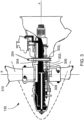
- Gasturbinentriebwerk (110), umfassend das System nach einem der Ansprüche 5 bis 9, ferner umfassend mindestens einen Sensor (212), der benachbart an der Rückkopplungsvorrichtung (204) montiert ist, wobei die Rückkopplungsvorrichtung (204) zum Drehen mit dem Rotor (130) und zum axialen Bewegen mit der Einstellung des Blattanstellwinkels der Blätter (310) gekoppelt ist und der mindestens eine Sensor (212) fest an einem statischen Teil des Triebwerks (110) montiert ist, und der mindestens eine Sensor (212) dazu konfiguriert ist, einen Durchgang der Vielzahl von ersten Positionsmarkierungen (402) und der mindestens einen zweiten Positionsmarkierung (404) zu erkennen, wenn sich die Rückkopplungsvorrichtung (204) um die Längsachse (A) dreht.
- Gasturbinentriebwerk (110), umfassend das System nach einem der Ansprüche 5 bis 9, ferner umfassend mindestens einen Sensor (212), der benachbart an der Rückkopplungsvorrichtung (204) montiert ist, wobei der mindestens eine Sensor (212) zum Drehen mit dem Rotor (130) und zum axialen Bewegen mit der Einstellung des Blattanstellwinkels der Blätter (310) gekoppelt ist und die Rückkopplungsvorrichtung (204) fest an einem statischen Teil des Triebwerks (110) montiert ist und der mindestens eine Sensor (212) dazu konfiguriert ist, einen relativen Durchgang der Vielzahl von ersten Positionsmarkierungen (402) und der mindestens einen zweiten Positionsmarkierung (404) zu erkennen, wenn sich der mindestens eine Sensor (212) um die Längsachse (A) dreht.
- Blattwinkelrückkopplungsbaugruppe (200) für einen Rotor (130) mit Luftfahrzeugblättern, wobei der Rotor (130) um eine Längsachse (A) drehbar ist und einen einstellbaren Blattanstellwinkel aufweist, wobei die Baugruppe (200) Folgendes umfasst:eine Rückkopplungsvorrichtung (204), die eine Fußfläche (304) aufweist, die eine erste Kante (3021) aufweist;eine Vielzahl von Positionsmarkierungen (402), die sich von der Fußfläche (304) erstreckt und im Wesentlichen parallel zu der Längsachse (A) ausgerichtet ist, wobei die Vielzahl von ersten Positionsmarkierungen (402) in Umfangsrichtung voneinander beabstandet ist;mindestens eine zweite Positionsmarkierung (404), die sich von der Fußfläche (304) erstreckt und zwischen zwei benachbarten ersten Positionsmarkierungen (402) in einem Winkel dazu positioniert ist, wobei die mindestens eine zweite Positionsmarkierung (404) ein Ende (406) aufweist, das benachbart an der ersten Kante (3021) positioniert und im Wesentlichen bündig damit ist, und die eine geometrische Mittellinie (C) aufweist, die einen spitzen Winkel mit der ersten Kante (3021) auf einer Seite der geometrischen Mittellinie (C) und einen stumpfen Winkel mit der ersten Kante (3021) auf der anderen Seite der geometrischen Mittellinie (C) ausbildet, wobei eine Materialextrusion (416) an dem Ende (406) bereitgestellt ist, um die volumetrische Größe des Endes (406) auf der Seite des spitzen Winkels zu erhöhen; undmindestens einen Sensor (212), der dazu konfiguriert ist, benachbart an der Rückkopplungsvorrichtung (204) montiert zu werden, wobei eine der Rückkopplungsvorrichtung (204) und der mindestens eine Sensor (212) dazu konfiguriert ist, zum Drehen mit dem Rotor (130) gekoppelt zu sein, und der mindestens eine Sensor (212) dazu konfiguriert ist, einen Durchgang der Vielzahl von ersten Positionsmarkierungen (402) und der mindestens einen zweiten Positionsmarkierung (404) zu erkennen, wenn sich eines der Rückkopplungsvorrichtung (204) und des mindestens einen Sensors (212), der dazu konfiguriert ist, zum Drehen mit dem Rotor (130) gekoppelt zu sein, um die Längsachse (A) dreht.
Applications Claiming Priority (2)
| Application Number | Priority Date | Filing Date | Title |
|---|---|---|---|
| US201962831252P | 2019-04-09 | 2019-04-09 | |
| US16/703,394 US11643187B2 (en) | 2019-04-09 | 2019-12-04 | Blade angle position feedback system with profiled marker terminations |
Publications (2)
| Publication Number | Publication Date |
|---|---|
| EP3722204A1 EP3722204A1 (de) | 2020-10-14 |
| EP3722204B1 true EP3722204B1 (de) | 2023-08-30 |
Family
ID=70285532
Family Applications (1)
| Application Number | Title | Priority Date | Filing Date |
|---|---|---|---|
| EP20169093.0A Active EP3722204B1 (de) | 2019-04-09 | 2020-04-09 | Blattwinkelpositionrückmeldesystem mit profilierten markierungsenden |
Country Status (3)
| Country | Link |
|---|---|
| US (1) | US11643187B2 (de) |
| EP (1) | EP3722204B1 (de) |
| PL (1) | PL3722204T3 (de) |
Families Citing this family (1)
| Publication number | Priority date | Publication date | Assignee | Title |
|---|---|---|---|---|
| CN112697438B (zh) * | 2020-12-23 | 2023-04-14 | 南京航空航天大学 | 基于音轮的涡桨发动机桨距-相角-转速测量装置及方法 |
Family Cites Families (8)
| Publication number | Priority date | Publication date | Assignee | Title |
|---|---|---|---|---|
| US2806402A (en) * | 1954-10-04 | 1957-09-17 | Gen Motors Corp | Propeller blade angle indicating device |
| GB2221306A (en) | 1988-07-29 | 1990-01-31 | Dowty Rotol Ltd | Assembly for determining the longitudinal displacement of a rotating shaft |
| KR20140137738A (ko) | 2013-05-23 | 2014-12-03 | 삼성전자주식회사 | 이미지 디스플레이 방법, 이미지 디스플레이 장치 및 기록 매체 |
| US9821901B2 (en) | 2013-11-21 | 2017-11-21 | Pratt & Whitney Canada Corp. | System and method for electronic propeller blade angle position feedback |
| US10486827B2 (en) | 2016-08-17 | 2019-11-26 | Pratt & Whitney Canada Corp. | Apparatus and methods for aircraft propeller control |
| US10889367B2 (en) * | 2017-04-24 | 2021-01-12 | Pratt & Whitney Canada Corp. | Feedback system for pitch-adjustable blades of aircraft bladed rotor |
| US20180320601A1 (en) | 2017-05-04 | 2018-11-08 | Rolls-Royce Corporation | Turbine assembly with auxiliary wheel |
| US11286038B2 (en) * | 2019-09-03 | 2022-03-29 | Pratt & Whitney Canada Corp. | Pitch control assembly for an aircraft-bladed rotor |
-
2019
- 2019-12-04 US US16/703,394 patent/US11643187B2/en active Active
-
2020
- 2020-04-09 PL PL20169093.0T patent/PL3722204T3/pl unknown
- 2020-04-09 EP EP20169093.0A patent/EP3722204B1/de active Active
Also Published As
| Publication number | Publication date |
|---|---|
| EP3722204A1 (de) | 2020-10-14 |
| US20200324876A1 (en) | 2020-10-15 |
| PL3722204T3 (pl) | 2024-02-19 |
| US11643187B2 (en) | 2023-05-09 |
Similar Documents
| Publication | Publication Date | Title |
|---|---|---|
| EP3730902B1 (de) | Schaufelwinkelpositionsrückkopplungssystem mit offset-sensoren | |
| EP3712057B1 (de) | Schaufelwinkelpositionsrückmeldungssystem mit erweiterten markern | |
| EP3831711B1 (de) | Vorrichtung zur erfassung des blattanstellwinkels mit variabler magnetischer permeabilität | |
| US11685514B2 (en) | Pitch control assembly for an aircraft-bladed rotor | |
| US11623735B2 (en) | Blade angle position feedback system with magnetic shield | |
| EP3744630B1 (de) | Rückkopplungsvorrichtung mit unterschiedlichen magnetischen permeabilitätszonen | |
| EP3722204B1 (de) | Blattwinkelpositionrückmeldesystem mit profilierten markierungsenden | |
| EP3838745B1 (de) | System und verfahren zur bestimmung einer axialen position einer rückkopplungsvorrichtung | |
| CA3077916A1 (en) | Blade angle position feedback system with profiled marker terminations | |
| EP3744629B1 (de) | Rückkopplungsvorrichtung mit nichtaxial ausgerichteten positionsmarkern | |
| CA3080300A1 (en) | Feedback device with differing magnetic permeability zones |
Legal Events
| Date | Code | Title | Description |
|---|---|---|---|
| PUAI | Public reference made under article 153(3) epc to a published international application that has entered the european phase |
Free format text: ORIGINAL CODE: 0009012 |
|
| STAA | Information on the status of an ep patent application or granted ep patent |
Free format text: STATUS: THE APPLICATION HAS BEEN PUBLISHED |
|
| AK | Designated contracting states |
Kind code of ref document: A1 Designated state(s): AL AT BE BG CH CY CZ DE DK EE ES FI FR GB GR HR HU IE IS IT LI LT LU LV MC MK MT NL NO PL PT RO RS SE SI SK SM TR |
|
| AX | Request for extension of the european patent |
Extension state: BA ME |
|
| STAA | Information on the status of an ep patent application or granted ep patent |
Free format text: STATUS: REQUEST FOR EXAMINATION WAS MADE |
|
| 17P | Request for examination filed |
Effective date: 20210414 |
|
| RBV | Designated contracting states (corrected) |
Designated state(s): AL AT BE BG CH CY CZ DE DK EE ES FI FR GB GR HR HU IE IS IT LI LT LU LV MC MK MT NL NO PL PT RO RS SE SI SK SM TR |
|
| STAA | Information on the status of an ep patent application or granted ep patent |
Free format text: STATUS: EXAMINATION IS IN PROGRESS |
|
| 17Q | First examination report despatched |
Effective date: 20211020 |
|
| GRAP | Despatch of communication of intention to grant a patent |
Free format text: ORIGINAL CODE: EPIDOSNIGR1 |
|
| STAA | Information on the status of an ep patent application or granted ep patent |
Free format text: STATUS: GRANT OF PATENT IS INTENDED |
|
| INTG | Intention to grant announced |
Effective date: 20230315 |
|
| GRAS | Grant fee paid |
Free format text: ORIGINAL CODE: EPIDOSNIGR3 |
|
| GRAA | (expected) grant |
Free format text: ORIGINAL CODE: 0009210 |
|
| STAA | Information on the status of an ep patent application or granted ep patent |
Free format text: STATUS: THE PATENT HAS BEEN GRANTED |
|
| AK | Designated contracting states |
Kind code of ref document: B1 Designated state(s): AL AT BE BG CH CY CZ DE DK EE ES FI FR GB GR HR HU IE IS IT LI LT LU LV MC MK MT NL NO PL PT RO RS SE SI SK SM TR |
|
| REG | Reference to a national code |
Ref country code: GB Ref legal event code: FG4D |
|
| REG | Reference to a national code |
Ref country code: CH Ref legal event code: EP |
|
| REG | Reference to a national code |
Ref country code: DE Ref legal event code: R096 Ref document number: 602020016501 Country of ref document: DE |
|
| REG | Reference to a national code |
Ref country code: IE Ref legal event code: FG4D |
|
| REG | Reference to a national code |
Ref country code: LT Ref legal event code: MG9D |
|
| REG | Reference to a national code |
Ref country code: NL Ref legal event code: MP Effective date: 20230830 |
|
| REG | Reference to a national code |
Ref country code: AT Ref legal event code: MK05 Ref document number: 1605131 Country of ref document: AT Kind code of ref document: T Effective date: 20230830 |
|
| PG25 | Lapsed in a contracting state [announced via postgrant information from national office to epo] |
Ref country code: GR Free format text: LAPSE BECAUSE OF FAILURE TO SUBMIT A TRANSLATION OF THE DESCRIPTION OR TO PAY THE FEE WITHIN THE PRESCRIBED TIME-LIMIT Effective date: 20231201 |
|
| PG25 | Lapsed in a contracting state [announced via postgrant information from national office to epo] |
Ref country code: IS Free format text: LAPSE BECAUSE OF FAILURE TO SUBMIT A TRANSLATION OF THE DESCRIPTION OR TO PAY THE FEE WITHIN THE PRESCRIBED TIME-LIMIT Effective date: 20231230 |
|
| PG25 | Lapsed in a contracting state [announced via postgrant information from national office to epo] |
Ref country code: SE Free format text: LAPSE BECAUSE OF FAILURE TO SUBMIT A TRANSLATION OF THE DESCRIPTION OR TO PAY THE FEE WITHIN THE PRESCRIBED TIME-LIMIT Effective date: 20230830 Ref country code: RS Free format text: LAPSE BECAUSE OF FAILURE TO SUBMIT A TRANSLATION OF THE DESCRIPTION OR TO PAY THE FEE WITHIN THE PRESCRIBED TIME-LIMIT Effective date: 20230830 Ref country code: NO Free format text: LAPSE BECAUSE OF FAILURE TO SUBMIT A TRANSLATION OF THE DESCRIPTION OR TO PAY THE FEE WITHIN THE PRESCRIBED TIME-LIMIT Effective date: 20231130 Ref country code: LV Free format text: LAPSE BECAUSE OF FAILURE TO SUBMIT A TRANSLATION OF THE DESCRIPTION OR TO PAY THE FEE WITHIN THE PRESCRIBED TIME-LIMIT Effective date: 20230830 Ref country code: LT Free format text: LAPSE BECAUSE OF FAILURE TO SUBMIT A TRANSLATION OF THE DESCRIPTION OR TO PAY THE FEE WITHIN THE PRESCRIBED TIME-LIMIT Effective date: 20230830 Ref country code: IS Free format text: LAPSE BECAUSE OF FAILURE TO SUBMIT A TRANSLATION OF THE DESCRIPTION OR TO PAY THE FEE WITHIN THE PRESCRIBED TIME-LIMIT Effective date: 20231230 Ref country code: HR Free format text: LAPSE BECAUSE OF FAILURE TO SUBMIT A TRANSLATION OF THE DESCRIPTION OR TO PAY THE FEE WITHIN THE PRESCRIBED TIME-LIMIT Effective date: 20230830 Ref country code: GR Free format text: LAPSE BECAUSE OF FAILURE TO SUBMIT A TRANSLATION OF THE DESCRIPTION OR TO PAY THE FEE WITHIN THE PRESCRIBED TIME-LIMIT Effective date: 20231201 Ref country code: FI Free format text: LAPSE BECAUSE OF FAILURE TO SUBMIT A TRANSLATION OF THE DESCRIPTION OR TO PAY THE FEE WITHIN THE PRESCRIBED TIME-LIMIT Effective date: 20230830 Ref country code: AT Free format text: LAPSE BECAUSE OF FAILURE TO SUBMIT A TRANSLATION OF THE DESCRIPTION OR TO PAY THE FEE WITHIN THE PRESCRIBED TIME-LIMIT Effective date: 20230830 |
|
| PG25 | Lapsed in a contracting state [announced via postgrant information from national office to epo] |
Ref country code: NL Free format text: LAPSE BECAUSE OF FAILURE TO SUBMIT A TRANSLATION OF THE DESCRIPTION OR TO PAY THE FEE WITHIN THE PRESCRIBED TIME-LIMIT Effective date: 20230830 |
|
| PG25 | Lapsed in a contracting state [announced via postgrant information from national office to epo] |
Ref country code: ES Free format text: LAPSE BECAUSE OF FAILURE TO SUBMIT A TRANSLATION OF THE DESCRIPTION OR TO PAY THE FEE WITHIN THE PRESCRIBED TIME-LIMIT Effective date: 20230830 |
|
| PG25 | Lapsed in a contracting state [announced via postgrant information from national office to epo] |
Ref country code: SM Free format text: LAPSE BECAUSE OF FAILURE TO SUBMIT A TRANSLATION OF THE DESCRIPTION OR TO PAY THE FEE WITHIN THE PRESCRIBED TIME-LIMIT Effective date: 20230830 Ref country code: RO Free format text: LAPSE BECAUSE OF FAILURE TO SUBMIT A TRANSLATION OF THE DESCRIPTION OR TO PAY THE FEE WITHIN THE PRESCRIBED TIME-LIMIT Effective date: 20230830 Ref country code: ES Free format text: LAPSE BECAUSE OF FAILURE TO SUBMIT A TRANSLATION OF THE DESCRIPTION OR TO PAY THE FEE WITHIN THE PRESCRIBED TIME-LIMIT Effective date: 20230830 Ref country code: EE Free format text: LAPSE BECAUSE OF FAILURE TO SUBMIT A TRANSLATION OF THE DESCRIPTION OR TO PAY THE FEE WITHIN THE PRESCRIBED TIME-LIMIT Effective date: 20230830 Ref country code: DK Free format text: LAPSE BECAUSE OF FAILURE TO SUBMIT A TRANSLATION OF THE DESCRIPTION OR TO PAY THE FEE WITHIN THE PRESCRIBED TIME-LIMIT Effective date: 20230830 Ref country code: PT Free format text: LAPSE BECAUSE OF FAILURE TO SUBMIT A TRANSLATION OF THE DESCRIPTION OR TO PAY THE FEE WITHIN THE PRESCRIBED TIME-LIMIT Effective date: 20240102 Ref country code: SK Free format text: LAPSE BECAUSE OF FAILURE TO SUBMIT A TRANSLATION OF THE DESCRIPTION OR TO PAY THE FEE WITHIN THE PRESCRIBED TIME-LIMIT Effective date: 20230830 |
|
| PGFP | Annual fee paid to national office [announced via postgrant information from national office to epo] |
Ref country code: CZ Payment date: 20240326 Year of fee payment: 5 Ref country code: GB Payment date: 20240321 Year of fee payment: 5 |