EP3722123B1 - Steuerstand für ein mit einer kabine ausgestattetes fahrzeug - Google Patents
Steuerstand für ein mit einer kabine ausgestattetes fahrzeug Download PDFInfo
- Publication number
- EP3722123B1 EP3722123B1 EP20161215.7A EP20161215A EP3722123B1 EP 3722123 B1 EP3722123 B1 EP 3722123B1 EP 20161215 A EP20161215 A EP 20161215A EP 3722123 B1 EP3722123 B1 EP 3722123B1
- Authority
- EP
- European Patent Office
- Prior art keywords
- cabin
- air
- accommodating space
- cladding
- air duct
- Prior art date
- Legal status (The legal status is an assumption and is not a legal conclusion. Google has not performed a legal analysis and makes no representation as to the accuracy of the status listed.)
- Active
Links
Images
Classifications
-
- B—PERFORMING OPERATIONS; TRANSPORTING
- B60—VEHICLES IN GENERAL
- B60H—ARRANGEMENTS OF HEATING, COOLING, VENTILATING OR OTHER AIR-TREATING DEVICES SPECIALLY ADAPTED FOR PASSENGER OR GOODS SPACES OF VEHICLES
- B60H1/00—Heating, cooling or ventilating devices
- B60H1/00507—Details, e.g. mounting arrangements, desaeration devices
- B60H1/00514—Details of air conditioning housings
- B60H1/0055—Details of air conditioning housings the housing or parts thereof being integrated in other devices, e.g. dashboard
-
- B—PERFORMING OPERATIONS; TRANSPORTING
- B60—VEHICLES IN GENERAL
- B60K—ARRANGEMENT OR MOUNTING OF PROPULSION UNITS OR OF TRANSMISSIONS IN VEHICLES; ARRANGEMENT OR MOUNTING OF PLURAL DIVERSE PRIME-MOVERS IN VEHICLES; AUXILIARY DRIVES FOR VEHICLES; INSTRUMENTATION OR DASHBOARDS FOR VEHICLES; ARRANGEMENTS IN CONNECTION WITH COOLING, AIR INTAKE, GAS EXHAUST OR FUEL SUPPLY OF PROPULSION UNITS IN VEHICLES
- B60K37/00—Dashboards
-
- B—PERFORMING OPERATIONS; TRANSPORTING
- B60—VEHICLES IN GENERAL
- B60H—ARRANGEMENTS OF HEATING, COOLING, VENTILATING OR OTHER AIR-TREATING DEVICES SPECIALLY ADAPTED FOR PASSENGER OR GOODS SPACES OF VEHICLES
- B60H1/00—Heating, cooling or ventilating devices
- B60H1/00357—Air-conditioning arrangements specially adapted for particular vehicles
- B60H1/00378—Air-conditioning arrangements specially adapted for particular vehicles for tractor or load vehicle cabins
-
- B—PERFORMING OPERATIONS; TRANSPORTING
- B60—VEHICLES IN GENERAL
- B60H—ARRANGEMENTS OF HEATING, COOLING, VENTILATING OR OTHER AIR-TREATING DEVICES SPECIALLY ADAPTED FOR PASSENGER OR GOODS SPACES OF VEHICLES
- B60H1/00—Heating, cooling or ventilating devices
- B60H1/00507—Details, e.g. mounting arrangements, desaeration devices
- B60H1/00557—Details of ducts or cables
- B60H1/00564—Details of ducts or cables of air ducts
-
- B—PERFORMING OPERATIONS; TRANSPORTING
- B60—VEHICLES IN GENERAL
- B60K—ARRANGEMENT OR MOUNTING OF PROPULSION UNITS OR OF TRANSMISSIONS IN VEHICLES; ARRANGEMENT OR MOUNTING OF PLURAL DIVERSE PRIME-MOVERS IN VEHICLES; AUXILIARY DRIVES FOR VEHICLES; INSTRUMENTATION OR DASHBOARDS FOR VEHICLES; ARRANGEMENTS IN CONNECTION WITH COOLING, AIR INTAKE, GAS EXHAUST OR FUEL SUPPLY OF PROPULSION UNITS IN VEHICLES
- B60K11/00—Arrangement in connection with cooling of propulsion units
- B60K11/06—Arrangement in connection with cooling of propulsion units with air cooling
-
- B—PERFORMING OPERATIONS; TRANSPORTING
- B60—VEHICLES IN GENERAL
- B60R—VEHICLES, VEHICLE FITTINGS, OR VEHICLE PARTS, NOT OTHERWISE PROVIDED FOR
- B60R13/00—Elements for body-finishing, identifying, or decorating; Arrangements or adaptations for advertising purposes
-
- B—PERFORMING OPERATIONS; TRANSPORTING
- B62—LAND VEHICLES FOR TRAVELLING OTHERWISE THAN ON RAILS
- B62D—MOTOR VEHICLES; TRAILERS
- B62D33/00—Superstructures for load-carrying vehicles
- B62D33/06—Drivers' cabs
- B62D33/0617—Drivers' cabs for tractors or off-the-road vehicles
-
- B—PERFORMING OPERATIONS; TRANSPORTING
- B66—HOISTING; LIFTING; HAULING
- B66C—CRANES; LOAD-ENGAGING ELEMENTS OR DEVICES FOR CRANES, CAPSTANS, WINCHES, OR TACKLES
- B66C13/00—Other constructional features or details
- B66C13/52—Details of compartments for driving engines or motors or of operator's stands or cabins
- B66C13/54—Operator's stands or cabins
-
- B—PERFORMING OPERATIONS; TRANSPORTING
- B60—VEHICLES IN GENERAL
- B60H—ARRANGEMENTS OF HEATING, COOLING, VENTILATING OR OTHER AIR-TREATING DEVICES SPECIALLY ADAPTED FOR PASSENGER OR GOODS SPACES OF VEHICLES
- B60H1/00—Heating, cooling or ventilating devices
- B60H1/00007—Combined heating, ventilating, or cooling devices
- B60H1/00207—Combined heating, ventilating, or cooling devices characterised by the position of the HVAC devices with respect to the passenger compartment
- B60H2001/00214—Devices in front of the passenger compartment
-
- B—PERFORMING OPERATIONS; TRANSPORTING
- B60—VEHICLES IN GENERAL
- B60K—ARRANGEMENT OR MOUNTING OF PROPULSION UNITS OR OF TRANSMISSIONS IN VEHICLES; ARRANGEMENT OR MOUNTING OF PLURAL DIVERSE PRIME-MOVERS IN VEHICLES; AUXILIARY DRIVES FOR VEHICLES; INSTRUMENTATION OR DASHBOARDS FOR VEHICLES; ARRANGEMENTS IN CONNECTION WITH COOLING, AIR INTAKE, GAS EXHAUST OR FUEL SUPPLY OF PROPULSION UNITS IN VEHICLES
- B60K2360/00—Indexing scheme associated with groups B60K35/00 or B60K37/00 relating to details of instruments or dashboards
- B60K2360/60—Structural details of dashboards or instruments
- B60K2360/65—Features of dashboards
- B60K2360/658—Dashboard parts used as air ducts
Definitions
- the invention relates to a cab for a working vehicle with a control stand with a plastic panel serving as a support for fittings and with air ducts for air conditioning the cab.
- a cabin of the type described is from the WO 2007063668 A1 known, wherein the cabin formed by a plurality of uprights and wall panels and the control station is arranged in the cabin.
- the carrier serves to cover the steering column and carries various fittings, in particular on a dashboard, such as switches, display elements and the like, without taking on special technical functions itself.
- a known method of manufacturing hollow bodies from plastic is rotational molding or the rotational molding process, in which a plastic melt cools and solidifies on the wall of a rotating tool.
- This method can be done with simple tools and low tool costs small and medium-sized series of workpieces with a relatively large construction volume, with great freedom in terms of shaping and openings or breakthroughs with continuous connections, threads, inserts, etc. are possible.
- the invention is therefore based on the object of creating a control stand of the type described at the outset that can be produced inexpensively and which allows air conditioning of a cab of a working machine in a simple and advantageous manner.
- the invention solves the problem in that the carrier is a structural component of the cabin and thus forms part of the cabin inner wall and the cabin outer wall of a cabin wall and that the carrier is rotationally molded in an integral design, with the carrier spacing the cabin inner wall and the, a trough-shaped
- the outer wall of the cabin is formed integrally with the inner wall of the cabin and forms a receiving space for an air-conditioning unit, and at least one passage that is formed integrally with the cabin and forms an air line is provided between the inner wall of the cabin and the receiving space of the outer wall of the cabin.
- the control stand according to the invention allows air conditioning of a cab of a working machine in a simple and advantageous manner, since it has all air lines required for air conditioning and is designed in such a way that it can accommodate an air conditioning unit, which means that long lines can be omitted and losses are kept low.
- Integral construction means that the beam is made from a single piece, i.e. rotationally molded.
- the beam serves as a structural component of the cabin.
- the carrier forms both at least part of the outer wall and at least part of the inner wall of the front part of the cabin.
- structural component is not necessarily to be understood as meaning that it is a load-bearing component.
- the carrier is designed as an at least partially load-bearing component.
- the front window of the cabin is placed on top of the carrier part and doors can be attached to the side be.
- the at least one integrally formed air line forms a passage between the inner wall of the cabin and the receiving space on the outer wall of the cabin, with the result that particularly short flow paths can be implemented.
- the support cavity can optionally be designed to be thermally or acoustically insulated and/or also serve to guide air.
- the carrier comprises at least one air duct for circulating air emanating from the cabin inner wall and at least one air duct for supply air, and at least one air duct for fresh air connected to the receiving space is assigned to the cabin outer wall. If, in addition, at least one air line is provided between the receiving space and an instrument panel associated with the interior wall of the cabin, then all the fresh air, circulating air and exhaust air lines are formed or provided in the panel.
- the carrier offers attachment options for all the usual vehicle fittings required. This means that the entire cabin air supply is integrated in the carrier and the air conditioning can be decoupled from the engine compartment.
- the receiving space can preferably be covered on the outside with a receiving space cover.
- the air conditioning unit is easily accessible for maintenance. This causes a significant increase in the efficiency of the air throughput due to particularly short air ducts compared to the prior art.
- there is no need for complex additional thermal insulation which results in significantly lower manufacturing and assembly costs due to fewer components in the overall system.
- the space gained in the engine compartment can be used for other purposes.
- the air conditioning unit does not necessarily include all of the components needed to cool the cabin, for example.
- at least one heat exchanger is arranged in the receiving space.
- An air conditioning compressor and condenser can also be arranged in another suitable position.
- the receiving space has a passage on the floor that forms a drain for condensation water and opens out in the area of the outer wall of the cabin.
- Cover grilles can be attached to the air ducts, with the cover grilles of the air duct for the circulating air and the air duct for the fresh air each having at least one air filter and the at least one air duct for the supply air being assigned an adjustable nozzle. All the necessary means for proper air flow and for air conditioning of the cabin are thus provided on the carrier.
- the carrier has a passage for a steering column. Furthermore, the invention relates to a control stand for a cabin and a work vehicle with a cabin according to the invention.
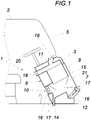
- the control station 1 for a work vehicle equipped with a cab 2 comprises a plastic panel serving as a support 3 for fittings 4 and air lines for air conditioning of the cab 2.
- the beam 3 is a structural component of the cab 2 and supports the windscreen 5 of the cab 2. This means that the windscreen 5 is arranged above the beam 3, and it does not necessarily have to bear on the beam 3 with its weight.
- a seal and/or a panel or lining can be arranged between the carrier 3 and the windscreen 5 .
- the carrier 3 forms part of the cabin inner wall 6 and the cabin outer wall 7 of a cabin wall.
- the carrier 3 is of integral design rotationally moulded, the carrier 3 comprising the cabin inner wall 6 and spaced therefrom the cabin outer wall 7 which forms a trough-shaped receiving space 8 for an air conditioning unit 9 and is formed in one piece with the cabin inner wall 6 .
- passages between the inner wall 6 of the cabin and the receiving space 8 of the outer wall 7 of the cabin, which are formed integrally with the carrier 3 and form air lines 10 , 11 , 12 , are provided.
- the cabin inner wall 6 comprises at least one air line 10 for circulating air and at least one air line 11 for supply air. At least one air line 12 for fresh air connected to the receiving space 8 is assigned to the outer wall 7 of the cabin. An air line 11 is provided between the receiving space 8 and an instrument panel 13 associated with the interior wall 6 of the cabin.
- the air conditioning unit 9 connected to the air lines 10, 11, 12 is inserted into the receiving space 8 and comprises an air distributor, in particular a device for switching between fresh air supply and circulating air, a heating, a cooling and a ventilation unit. Since this is a standard assembly, it is not shown in detail.
- the receiving space 8 On the bottom side, the receiving space 8 has a passage that forms a drain 14 for condensed water and opens out in the area of the outer wall 7 of the cabin.
- the receiving space 8 of the cabin outer wall 7 is covered on the outside with a receiving space cover 15 .
- Cover grilles 16 are attached to the air ducts 10, 11, 12, at least one air filter 17 each being assigned to the cover grille 16 of the air duct 10 for the circulating air and the air duct 12 for the fresh air, and adjustable nozzles 18 being assigned to the air ducts 11 for the supply air.
- the carrier 3 has an opening 19 for a steering column 20 .
- the air flow which consists of an optimized quantity ratio of outside air and inside air required by standards, is sucked through the air-conditioning unit 9 mounted in the support 3 .
- the condensation water produced by the evaporator in the air conditioning unit 9 is kept away from the air filters 17 by deflectors 21 and collected in the support 3 and discharged through the drain 14 .
- the air is pressed by the ventilation unit through the air distributor integrated in the carrier 3 and emerges at the appropriate points depending on the setting of the different nozzles 18 .
- Optimum air distribution in the passenger compartment is ensured by matching the cross-sections in the air distributor.
- the nozzles 18 are arranged in such a way that the glass panes in the cabin are de-iced as quickly as possible and the machine operator is hit by a flow.
Landscapes
- Engineering & Computer Science (AREA)
- Mechanical Engineering (AREA)
- Chemical & Material Sciences (AREA)
- Combustion & Propulsion (AREA)
- Transportation (AREA)
- Physics & Mathematics (AREA)
- Thermal Sciences (AREA)
- Body Structure For Vehicles (AREA)
- Air-Conditioning For Vehicles (AREA)
- Forklifts And Lifting Vehicles (AREA)
- Lighting Device Outwards From Vehicle And Optical Signal (AREA)
Description
- Die Erfindung bezieht sich auf eine Kabine für ein Arbeitsfahrzeug mit einem Steuerstand mit einer als Träger für Armaturen dienenden Kunststoffverkleidung und mit Luftleitungen zur Klimatisierung der Kabine.
- Eine Kabine der geschilderten Art ist aus der
WO 2007063668 A1 bekannt, wobei die Kabine von einer Mehrzahl von Stehern und Wandplatten gebildet und der Steuerstand in der Kabine angeordnet ist. Der Träger dient bei derzeitigen Lösungen der Verkleidung der Lenksäule und trägt diverse Armaturen insbesondere auf einem Armaturenbrett, wie Schalter, Anzeigeelemente u. dgl. ohne dabei selbst spezielle technische Funktionen zu übernehmen. - Zur Klimatisierung, also zum Umwälzen und/oder Zuführen von Luft, zum Kühlen bzw. Heizen der Luft, von Kabinen von Arbeitsmaschinen ist es bekannt geschweißte, aufwändig isolierte Blechkonsolen, mit teilweise sehr langen Ansaug- und/oder Ausblaskanälen vorzusehen. Diese Blechkonsolen sind meist im Motorraum verbaut, in dem naturgemäße erhöhte Umgebungstemperaturen vorherrschen, was nicht nur die langen Leitungen mit den damit verbundenen Strömungsverlusten bedingt, sondern wegen der hohen Temperaturen auch ungünstige Arbeitsbedingungen für ein Klimagerät zur Folge hat. Zudem haben derartige Lösungen einen hohen Platzbedarf im Motorraum. Durch die hohen Temperaturen im Motorraum ist zudem ein großer Aufwand hinsichtlich der thermischen Isolierung nötig. Bekannte nachrüstbare Aufdachlösungen verursachen hohe Kosten und erhöhen zudem die Maschinenhöhe.
- Eine bekanntes Verfahren Hohlkörper aus Kunststoff zu fertigen ist das Rotationsformen, bzw. das Rotationsschmelzverfahren, bei dem eine Kunststoffschmelze an der Wandung eines rotierenden Werkzeuges abkühlt und erstarrt. Mit diesem Verfahren lassen sich mit einfachen Werkzeugen und niedrigen Werkzeugkosten kleine und mittlere Serien von Werkstücken mit verhältnismäßig großem Bauvolumen fertigen, wobei hinsichtlich der Formgebung große Freiheiten vorherrschen und Öffnungen beziehungsweise Durchbrüche mit durchgehenden Verbindungen, Gewinden, Einlageteilen usw. möglich sind.
- Der Erfindung liegt somit die Aufgabe zugrunde, einen günstig herstellbaren Steuerstand der eingangs geschilderten Art zu schaffen, welcher in einfacher und vorteilhafter Weise eine Klimatisierung einer Kabine einer Arbeitsmaschine erlaubt.
- Die Erfindung löst die gestellte Aufgabe dadurch, dass der Träger ein strukturelles Bauteil der Kabine ist und damit einen Teil der Kabineninnenwandung und der Kabinenaußenwandung einer Kabinenwand bildet und dass der Träger in Integralbauweise rotationsgeformt ist, wobei der Träger die Kabineninnenwandung und davon beabstandet die, einen muldenförmigen Aufnahmeraum für ein Klimaaggregat bildende, einstückig mit der Kabineninnenwandung geformte Kabinenaußenwandung umfasst und wobei wenigstens ein integral mitgeformter, eine Luftleitung bildender Durchlass zwischen Kabineninnenwandung und dem Aufnahmeraum der Kabinenaußenwandung vorgesehen ist.
- Der erfindungsgemäße Steuerstand erlaubt in einfacher und vorteilhafter Weise eine Klimatisierung einer Kabine einer Arbeitsmaschine, da er sämtliche zur Klimatisierung erforderlichen Luftleitungen aufweist und derart ausgebildet ist, dass er ein Klimaaggregat aufnehmen kann, womit lange Leitungen entfallen können und Verluste geringgehalten werden. Integralbauweise bedeutet, dass der Träger aus einem einzigen Stück hergestellt, eben rotationsgeformt ist. Der Träger dient als strukturelles Bauteil der Kabine. Das bedeutet, der Träger bildet sowohl wenigstens einen Teil der Außen- als auch wenigstens einen Teil der Innenwandung des vorderen Teils der Kabine. Der Begriff strukturelles Bauteil ist nicht notwendiger Weise dahingehend zu verstehen, dass es sich um ein tragendes Bauteil handelt. In einer bevorzugten Ausführungsform ist der Träger als zumindest teilweise tragendes Bauteil ausgebildet. Auf das Trägerteil wird oben die Frontscheibe der Kabine aufgesetzt und können seitlich Türen angeschlagen sein. Die wenigstens eine integral mitgeformte, Luftleitung bildet einen Durchlass zwischen Kabineninnenwandung und dem Aufnahmeraum an der Kabinenaußenwandung, womit besonders kurze Strömungswege realisiert werden können. Der Trägerhohlraum kann gegebenenfalls thermisch bzw. akustisch gedämmt ausgeführt sein und/oder ebenfalls der Luftführung dienen.
- Insbesondere umfasst der Träger wenigstens eine von der Kabineninnenwandung ausgehende Luftleitung für Umluft und wenigstens eine Luftleitung für Zuluft und ist der Kabinenaußenwandung wenigstens eine an den Aufnahmeraum angeschlossene Luftleitung für Frischluft zugeordnet. Ist zudem wenigstens eine Luftleitung zwischen Aufnahmeraum und einem der Kabineninnenwandung zugeordneten Armaturenträger vorgesehen, so sind alle Frischluft-, Umluft- und Ausblasluftleitungen im Träger ausgebildet bzw. vorgesehen. Zudem bietet der Träger Befestigungsmöglichkeiten für alle üblichen benötigten Fahrzeugarmaturen. Damit ist die gesamte Kabinen-Luftversorgung im Träger integriert und kann die Klimatisierung vom Motorraum entkoppelt werden.
- Dies insbesondere, wenn in den Aufnahmeraum ein an die Luftleitungen angeschlossenes Klimaaggregat eingesetzt ist, das einen Luftverteiler, eine Heizung, eine Kühlung und eine Ventilationseinheit umfasst. Der Aufnahmeraum ist außenseitig vorzugsweise mit einem Aufnahmeraumdeckel abdeckbar. Damit ist das Klimaaggregat problemlos zwecks Wartung zugänglich. Dies bewirkt eine wesentliche Effizienzsteigerung des Luftdurchsatzes aufgrund besonders kurzer Luftkanäle gegenüber dem Stand der Technik. Zudem kann auf eine aufwändige zusätzliche thermische Isolierung verzichtet werden, was wesentlich geringere Herstell- und Montagekosten durch weniger Komponenten im Gesamtsystem zur Folge hat. Der damit gewonnene Platz im Motorraum kann anderweitig verwendet werden. Das Klimaaggregat umfasst nicht notwendigerweise alle Komponenten um beispielsweise die Kühlung der Kabine bereit zu stellen. Insbesondere ist zumindest ein Wärmetauscher im Aufnahmeraum angeordnet. Ein Klimakompressor und Kondensator können auch einer anderweitigen geeigneten Position angeordnet sein.
- Um beispielsweise bei der Klimatisierung anfallendes Kondenswasser vorteilhaft aus dem Träger ableiten zu können, wird vorgeschlagen, dass der Aufnahmeraum bodenseitig einen, einen Abfluss für Kondenswasser bildenden und im Bereich der Kabinenaußenwandung ausmündenden Durchlass aufweist.
- An die Luftleitungen können Abdeckgitter angesetzt sein, wobei den Abdeckgittern der Luftleitung für die Umluft und der Luftleitung für die Frischluft je wenigstens ein Luftfilter und wobei der wenigstens eine Luftleitung für die Zuluft eine einstellbare Düse zugeordnet ist. Damit sind am Träger alle erforderlichen Mittel zur ordentlichen Luftführung und zur Klimatisierung der Kabine vorgesehen.
- Für eine kompakte Bauweise der Kabine ist es von Vorteil, wenn der Träger einen Durchlass für eine Lenksäule aufweist. Des Weiteren betrifft die Erfindung einen Steuerstand für eine Kabine und ein Arbeitsfahrzeug mit einer erfindungsgemäßen Kabine.
- In der Zeichnung ist der Erfindungsgegenstand beispielsweise schematisch dargestellt. Es zeigen
-
Fig. 1 einen Steuerstand im Querschnitt, -
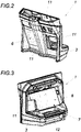
Fig. 2 einen Steuerstand von hinten schräg oben und -
Fig. 3 den Steuerstand von vorne schräg oben. - Der Steuerstand 1 für ein mit einer Kabine 2 ausgestattetes, nicht näher dargestelltes, Arbeitsfahrzeug umfasst eine als Träger 3 für Armaturen 4 dienende Kunststoffverkleidung und Luftleitungen zur Klimatisierung der Kabine 2.
- Der Träger 3 ist ein strukturelles Bauteil der Kabine 2 und trägt die Frontscheibe 5 der Kabine 2. Dies bedeutet, dass die Frontscheibe 5 oberhalb des Trägers 3 angeordnet ist, wobei diese nicht notwendigerweise mit ihrem Gewicht auf dem Träger 3 lasten muss. Zwischen dem Träger 3 und der Frontscheibe 5 kann eine Dichtung und/oder eine Blende oder Verkleidung angeordnet sein. Der Träger 3 bildet einen Teil der Kabineninnenwandung 6 und der Kabinenaußenwandung 7 einer Kabinenwand. Darüber hinaus ist der Träger 3 in Integralbauweise rotationsgeformt, wobei der Träger 3 die Kabineninnenwandung 6 und davon beabstandet die, einen muldenförmigen Aufnahmeraum 8 für ein Klimaaggregat 9 bildende, einstückig mit der Kabineninnenwandung 6 geformte Kabinenaußenwandung 7 umfasst. Zudem sind im Träger 3 integral mitgeformte, Luftleitungen 10, 11, 12 bildende Durchlässe zwischen Kabineninnenwandung 6 und dem Aufnahmeraum 8 der Kabinenaußenwandung 7 vorgesehen sind.
- Die Kabineninnenwandung 6 umfasst wenigstens eine Luftleitung 10 für Umluft und wenigstens eine Luftleitung 11 für Zuluft. Der Kabinenaußenwandung 7 ist wenigstens eine an den Aufnahmeraum 8 angeschlossene Luftleitung 12 für Frischluft zugeordnet. Eine Luftleitung 11 ist zwischen Aufnahmeraum 8 und einem der Kabineninnenwandung 6 zugeordneten Armaturenträger 13 vorgesehen.
- In den Aufnahmeraum 8 ist das an die Luftleitungen 10, 11, 12 angeschlossene Klimaaggregat 9 eingesetzt, das einen Luftverteiler, insbesondere eine Vorrichtung zum Umschalten zwischen Frischluftzufuhr und Umluft, eine Heizung, eine Kühlung und eine Ventilationseinheit umfasst. Da es sich dabei um eine Standardbaugruppe handelt ist diese nicht näher dargestellt.
- Der Aufnahmeraum 8 weist bodenseitig einen, einen Abfluss 14 für Kondenswasser bildenden und im Bereich der Kabinenaußenwandung 7 ausmündenden Durchlass auf. Der Aufnahmeraum 8 der Kabinenaußenwandung 7 ist außenseitig mit einem Aufnahmeraumdeckel 15 abgedeckt. An die Luftleitungen 10, 11, 12 sind Abdeckgitter 16 angesetzt, wobei dem Abdeckgitter 16 der Luftleitung 10 für die Umluft und der Luftleitung 12 für die Frischluft je wenigstens ein Luftfilter 17 und wobei den Luftleitungen 11 für die Zuluft einstellbare Düsen 18 zugeordnet sind. Der Träger 3 weist einen Durchlass 19 für eine Lenksäule 20 auf.
- Im vorderen, unteren Bereich der Kabinenaußenwandung 7 wird durch ein abnehmbares Abdeckgitter 16 die Außenluft durch den Luftfilter 17 gesaugt. Das nach unten laufende Regenwasser wird von einem Abweiser 21 abgeleitet, um den Luftfilter 17 vor Nässe zu schützen. Im Bereich der Pedale wird die Kabineninnenluft durch das abnehmbare Abdeckgitter 16 an der Kabineninnenwandung 7 durch den Luftfilter 17 gesaugt. Beide Luftfilter 17 sind durch Abnehmen der jeweiligen Abdeckgitter 16 zu wechseln.
- Der aus einem normativ geforderten, optimierten Mengenverhältnis von Außen- und Innenluft bestehenden Luftstrom wird durch das im Träger 3 montierte Klimaaggregat 9 gesaugt. Das, durch den im Klimaaggregat 9 befindlichen Verdampfer, anfallende Kondenswasser wird durch Abweiser 21 von den Luftfiltern 17 ferngehalten und im Träger 3 gesammelt und durch den Abfluss 14 abgeführt.
- Die Luft wird von der Ventilationseinheit durch den im Träger 3 integrierten Luftverteiler gedrückt und tritt je nach Einstellung der unterschiedlichen Düsen 18 an den entsprechenden Stellen aus.
- Durch Abstimmung der Querschnitte im Luftverteiler wird eine optimale Luftverteilung im Fahrgastraum gewährleistet, dabei sind die Düsen 18 so angeordnet, dass die Glasscheiben in der Kabine möglichst schnell enteist und der Maschinenführer angeströmt wird.
Claims (10)
- Kabine (2) für ein Arbeitsfahrzeug mit einem Steuerstand (1) mit einer als Träger (3) für Armaturen (4) dienenden Kunststoffverkleidung und mit Luftleitungen (10, 11) zur Klimatisierung der Kabine (2) , dadurch gekennzeichnet, dass der Träger (3) ein strukturelles Bauteil der Kabine (2) ist und damit einen Teil der Kabineninnenwandung (6) und der Kabinenaußenwandung (7) einer Kabinenwand bildet und dass der Träger (3) in Integralbauweise rotationsgeformt ist, wobei der Träger (3) die Kabineninnenwandung (6) und davon beabstandet die, einen muldenförmigen Aufnahmeraum für ein Klimaaggregat (9) bildende, einstückig mit der Kabineninnenwandung (6) geformte Kabinenaußenwandung (7) umfasst und wobei wenigstens ein integral mitgeformter, eine Luftleitung (10, 11) bildender Durchlass zwischen Kabineninnenwandung (6) und dem Aufnahmeraum der Kabinenaußenwandung (7) vorgesehen ist.
- Kabine (2) nach Anspruch 1, dadurch gekennzeichnet, dass die Kabineninnenwandung (6) ausgehende Luftleitung (10) für Umluft und wenigstens eine Luftleitung (11) für Zuluft umfasst und dass der Kabinenaußenwandung (7) wenigstens eine an den Aufnahmeraum angeschlossene Luftleitung (12) für Frischluft zugeordnet ist.
- Kabine (2) nach Anspruch 1 oder 2, dadurch gekennzeichnet, dass wenigstens eine Luftleitung (11) zwischen Aufnahmeraum (8) und einem der Kabineninnenwandung (6) zugeordneten Armaturenträger (13) vorgesehen ist.
- Kabine (2) nach einem der Ansprüche 1 bis 3, dadurch gekennzeichnet, dass in den Aufnahmeraum ein an die Luftleitungen (10, 11, 12) angeschlossenes Klimaaggregat (9) eingesetzt ist, das einen Luftverteiler, eine Heizung, eine Kühlung und eine Ventilationseinheit umfasst.
- Kabine (2) nach einem der Ansprüche 1 bis 4, dadurch gekennzeichnet, dass der Aufnahmeraum (8) bodenseitig einen, einen Abfluss (14) für Kondenswasser bildenden und im Bereich der Kabinenaußenwandung (7) ausmündenden Durchlass aufweist.
- Kabine (2) nach einem der Ansprüche 1 bis 5, dadurch gekennzeichnet, dass der Aufnahmeraum (8) außenseitig mit einem Aufnahmeraumdeckel (15) abgedeckbar ist.
- Kabine (2) nach einem der Ansprüche 2 bis 6, dadurch gekennzeichnet, dass an die Luftleitungen (10, 11, 12) Abdeckgitter (16) angesetzt sind, wobei den Abdeckgittern der Luftleitung (10) für die Umluft und der Luftleitung (12) für die Frischluft je wenigstens ein Luftfilter (17) und wobei der wenigstens eine Luftleitung (11) für die Zuluft eine einstellbare Düse (18) zugeordnet ist.
- Kabine (2) nach einem der Ansprüche 1 bis 7, dadurch gekennzeichnet, dass der Träger (3) einen Durchlass (19) für eine Lenksäule (20) aufweist.
- Steuerstand (1) für eine Kabine (2) nach einem der Ansprüche 1 bis 8.
- Arbeitsfahrzeug mit einer Kabine (2) nach einem der Ansprüche 1 bis 8.
Applications Claiming Priority (1)
| Application Number | Priority Date | Filing Date | Title |
|---|---|---|---|
| ATA50309/2019A AT522360B1 (de) | 2019-04-09 | 2019-04-09 | Steuerstand für ein mit einer Kabine ausgestattetes Arbeitsfahrzeug |
Publications (2)
| Publication Number | Publication Date |
|---|---|
| EP3722123A1 EP3722123A1 (de) | 2020-10-14 |
| EP3722123B1 true EP3722123B1 (de) | 2022-06-01 |
Family
ID=69779837
Family Applications (1)
| Application Number | Title | Priority Date | Filing Date |
|---|---|---|---|
| EP20161215.7A Active EP3722123B1 (de) | 2019-04-09 | 2020-03-05 | Steuerstand für ein mit einer kabine ausgestattetes fahrzeug |
Country Status (3)
| Country | Link |
|---|---|
| EP (1) | EP3722123B1 (de) |
| AT (1) | AT522360B1 (de) |
| ES (1) | ES2921309T3 (de) |
Family Cites Families (12)
| Publication number | Priority date | Publication date | Assignee | Title |
|---|---|---|---|---|
| AT346711B (de) * | 1974-07-05 | 1978-11-27 | Jenbacher Werke Ag | Klimatisierungseinrichtung fuer insassenraeume |
| DE3437791A1 (de) * | 1984-10-16 | 1986-04-24 | Klöckner-Humboldt-Deutz AG, 5000 Köln | Bedienungskonsole fuer den fahrerstand eines schleppers |
| DE4001148A1 (de) * | 1990-01-17 | 1991-07-18 | Deere & Co | Belueftungseinrichtung fuer fahrzeugkabine |
| DE19842931C1 (de) * | 1998-09-18 | 2000-01-27 | Bentec Gmbh Drilling & Oilfield Systems | Konsole eines Fahrstandes, insbesondere einer Bohranlage |
| JP3747911B2 (ja) * | 2003-01-31 | 2006-02-22 | 井関農機株式会社 | トラクタのエアコン取付装置 |
| JP2005153834A (ja) * | 2003-11-28 | 2005-06-16 | Sanden Corp | 車両用空調装置 |
| JP4945122B2 (ja) * | 2005-12-01 | 2012-06-06 | 株式会社小松製作所 | 建設機械用キャブ |
| CN200996157Y (zh) * | 2006-08-28 | 2007-12-26 | 卡特彼勒(徐州)设计中心有限公司 | 用于工程机械车辆的驾驶室及包括其的车辆 |
| GB0819632D0 (en) * | 2008-10-27 | 2008-12-03 | Agco Gmbh | Tractor cab air filter housings |
| IT1401209B1 (it) * | 2010-07-02 | 2013-07-12 | Cnh Italia Spa | Cabina per veicolo agricolo attrezzata con un sistema di ventilazione e di condizionamento dell'aria |
| JP5349437B2 (ja) * | 2010-09-22 | 2013-11-20 | 株式会社クボタ | 旋回作業機 |
| CN106915218B (zh) * | 2017-03-23 | 2019-11-12 | 烟台镇泰滚塑有限公司 | 一种内置空调的独立双风道滚塑顶棚 |
-
2019
- 2019-04-09 AT ATA50309/2019A patent/AT522360B1/de active
-
2020
- 2020-03-05 ES ES20161215T patent/ES2921309T3/es active Active
- 2020-03-05 EP EP20161215.7A patent/EP3722123B1/de active Active
Also Published As
| Publication number | Publication date |
|---|---|
| EP3722123A1 (de) | 2020-10-14 |
| AT522360A1 (de) | 2020-10-15 |
| AT522360B1 (de) | 2021-02-15 |
| ES2921309T3 (es) | 2022-08-23 |
Similar Documents
| Publication | Publication Date | Title |
|---|---|---|
| DE69301785T2 (de) | Vorrichtung für die Heizung, Lüftung und/oder Klimatisierung eines Fahrzeuginnenraumes | |
| DE102009042269A1 (de) | Klimaanlage | |
| DE19814581B4 (de) | Klimaanlage für ein Kraftfahrzeug | |
| EP1228907B1 (de) | Klimagerät für ein Kraftfahrzeug | |
| DE69204090T2 (de) | Verfahren und Vorrichtung für Heizung, Lüftung und Klimaanlage für Motorfahrzeuginnenraum. | |
| DE10308084B4 (de) | Kühleinrichtung für ein Kraftfahrzeug-Antriebsaggregat | |
| EP3722123B1 (de) | Steuerstand für ein mit einer kabine ausgestattetes fahrzeug | |
| EP0425721B1 (de) | Anordnung zur Belüftung des Fahrgastraumes eines Kraftfahrzeuges | |
| DE10016433B4 (de) | Klimaanlage für ein Kraftfahrzeug | |
| DE10211927B4 (de) | Fahrzeugdach mit einer Belüftungsvorrichtung | |
| CN110733468A (zh) | 车辆的调节的空气分配系统 | |
| DE102008052112B4 (de) | Klimatisierungsanordnung für einen Führerstand | |
| DE19923189C1 (de) | Klimaanlage zur Klimatisierung des Fonds einer Fahrgastzelle | |
| DE102018117968B4 (de) | Luftverteileinrichtung für eine Mehrzonen-Klimaanlage und Mehrzonen-Klimaanlage für Kraftfahrzeuge | |
| DE102006009162B4 (de) | Heizungs-, Lüftungs- und Klimatisierungsanlage für Kraftfahrzeuge | |
| EP3616950B1 (de) | Kraftfahrzeug mit einem wärmetauscher | |
| DE102021101511B4 (de) | Elektrofahrzeug | |
| DE10026380B4 (de) | Einrichtung zur Klimatisierung eines Kraftfahrzeug-Innenraums | |
| DE19742566C1 (de) | Vorrichtung zur Luftverteilung in einem Fahrzeuginnenraum | |
| DE10112969A1 (de) | Klimaanlage für ein Kraftfahrzeug | |
| DE2901920C2 (de) | Reiseomnibus mit mindestens einer Vorrichtung zum Belüften, Beheizen und/oder Klimatisieren | |
| DE202016101208U1 (de) | Niederprofillüftungsanlage für ein Kraftfahrzeug | |
| EP1526016B1 (de) | Klimatisierungsvorrichtung, insbesondere für ein Kraftfahrzeug | |
| WO2013178308A1 (de) | Klimatisierungsvorrichtung | |
| DE10255803B3 (de) | Fahrgastzelle |
Legal Events
| Date | Code | Title | Description |
|---|---|---|---|
| PUAI | Public reference made under article 153(3) epc to a published international application that has entered the european phase |
Free format text: ORIGINAL CODE: 0009012 |
|
| STAA | Information on the status of an ep patent application or granted ep patent |
Free format text: STATUS: THE APPLICATION HAS BEEN PUBLISHED |
|
| AK | Designated contracting states |
Kind code of ref document: A1 Designated state(s): AL AT BE BG CH CY CZ DE DK EE ES FI FR GB GR HR HU IE IS IT LI LT LU LV MC MK MT NL NO PL PT RO RS SE SI SK SM TR |
|
| AX | Request for extension of the european patent |
Extension state: BA ME |
|
| STAA | Information on the status of an ep patent application or granted ep patent |
Free format text: STATUS: REQUEST FOR EXAMINATION WAS MADE |
|
| 17P | Request for examination filed |
Effective date: 20210408 |
|
| RBV | Designated contracting states (corrected) |
Designated state(s): AL AT BE BG CH CY CZ DE DK EE ES FI FR GB GR HR HU IE IS IT LI LT LU LV MC MK MT NL NO PL PT RO RS SE SI SK SM TR |
|
| GRAP | Despatch of communication of intention to grant a patent |
Free format text: ORIGINAL CODE: EPIDOSNIGR1 |
|
| STAA | Information on the status of an ep patent application or granted ep patent |
Free format text: STATUS: GRANT OF PATENT IS INTENDED |
|
| RIC1 | Information provided on ipc code assigned before grant |
Ipc: B60K 37/00 20060101ALI20220127BHEP Ipc: B60K 37/04 20060101ALI20220127BHEP Ipc: B62D 33/06 20060101ALI20220127BHEP Ipc: B60H 1/00 20060101AFI20220127BHEP |
|
| INTG | Intention to grant announced |
Effective date: 20220211 |
|
| GRAS | Grant fee paid |
Free format text: ORIGINAL CODE: EPIDOSNIGR3 |
|
| GRAA | (expected) grant |
Free format text: ORIGINAL CODE: 0009210 |
|
| STAA | Information on the status of an ep patent application or granted ep patent |
Free format text: STATUS: THE PATENT HAS BEEN GRANTED |
|
| AK | Designated contracting states |
Kind code of ref document: B1 Designated state(s): AL AT BE BG CH CY CZ DE DK EE ES FI FR GB GR HR HU IE IS IT LI LT LU LV MC MK MT NL NO PL PT RO RS SE SI SK SM TR |
|
| REG | Reference to a national code |
Ref country code: GB Ref legal event code: FG4D Free format text: NOT ENGLISH |
|
| REG | Reference to a national code |
Ref country code: AT Ref legal event code: REF Ref document number: 1495150 Country of ref document: AT Kind code of ref document: T Effective date: 20220615 Ref country code: CH Ref legal event code: EP Ref country code: DE Ref legal event code: R096 Ref document number: 502020001154 Country of ref document: DE |
|
| REG | Reference to a national code |
Ref country code: IE Ref legal event code: FG4D Free format text: LANGUAGE OF EP DOCUMENT: GERMAN |
|
| REG | Reference to a national code |
Ref country code: ES Ref legal event code: FG2A Ref document number: 2921309 Country of ref document: ES Kind code of ref document: T3 Effective date: 20220823 |
|
| REG | Reference to a national code |
Ref country code: LT Ref legal event code: MG9D |
|
| REG | Reference to a national code |
Ref country code: NL Ref legal event code: MP Effective date: 20220601 |
|
| PG25 | Lapsed in a contracting state [announced via postgrant information from national office to epo] |
Ref country code: SE Free format text: LAPSE BECAUSE OF FAILURE TO SUBMIT A TRANSLATION OF THE DESCRIPTION OR TO PAY THE FEE WITHIN THE PRESCRIBED TIME-LIMIT Effective date: 20220601 Ref country code: NO Free format text: LAPSE BECAUSE OF FAILURE TO SUBMIT A TRANSLATION OF THE DESCRIPTION OR TO PAY THE FEE WITHIN THE PRESCRIBED TIME-LIMIT Effective date: 20220901 Ref country code: LT Free format text: LAPSE BECAUSE OF FAILURE TO SUBMIT A TRANSLATION OF THE DESCRIPTION OR TO PAY THE FEE WITHIN THE PRESCRIBED TIME-LIMIT Effective date: 20220601 Ref country code: HR Free format text: LAPSE BECAUSE OF FAILURE TO SUBMIT A TRANSLATION OF THE DESCRIPTION OR TO PAY THE FEE WITHIN THE PRESCRIBED TIME-LIMIT Effective date: 20220601 Ref country code: GR Free format text: LAPSE BECAUSE OF FAILURE TO SUBMIT A TRANSLATION OF THE DESCRIPTION OR TO PAY THE FEE WITHIN THE PRESCRIBED TIME-LIMIT Effective date: 20220902 Ref country code: FI Free format text: LAPSE BECAUSE OF FAILURE TO SUBMIT A TRANSLATION OF THE DESCRIPTION OR TO PAY THE FEE WITHIN THE PRESCRIBED TIME-LIMIT Effective date: 20220601 Ref country code: BG Free format text: LAPSE BECAUSE OF FAILURE TO SUBMIT A TRANSLATION OF THE DESCRIPTION OR TO PAY THE FEE WITHIN THE PRESCRIBED TIME-LIMIT Effective date: 20220901 |
|
| PG25 | Lapsed in a contracting state [announced via postgrant information from national office to epo] |
Ref country code: RS Free format text: LAPSE BECAUSE OF FAILURE TO SUBMIT A TRANSLATION OF THE DESCRIPTION OR TO PAY THE FEE WITHIN THE PRESCRIBED TIME-LIMIT Effective date: 20220601 Ref country code: PL Free format text: LAPSE BECAUSE OF FAILURE TO SUBMIT A TRANSLATION OF THE DESCRIPTION OR TO PAY THE FEE WITHIN THE PRESCRIBED TIME-LIMIT Effective date: 20220601 Ref country code: LV Free format text: LAPSE BECAUSE OF FAILURE TO SUBMIT A TRANSLATION OF THE DESCRIPTION OR TO PAY THE FEE WITHIN THE PRESCRIBED TIME-LIMIT Effective date: 20220601 |
|
| PG25 | Lapsed in a contracting state [announced via postgrant information from national office to epo] |
Ref country code: NL Free format text: LAPSE BECAUSE OF FAILURE TO SUBMIT A TRANSLATION OF THE DESCRIPTION OR TO PAY THE FEE WITHIN THE PRESCRIBED TIME-LIMIT Effective date: 20220601 |
|
| PG25 | Lapsed in a contracting state [announced via postgrant information from national office to epo] |
Ref country code: SM Free format text: LAPSE BECAUSE OF FAILURE TO SUBMIT A TRANSLATION OF THE DESCRIPTION OR TO PAY THE FEE WITHIN THE PRESCRIBED TIME-LIMIT Effective date: 20220601 Ref country code: SK Free format text: LAPSE BECAUSE OF FAILURE TO SUBMIT A TRANSLATION OF THE DESCRIPTION OR TO PAY THE FEE WITHIN THE PRESCRIBED TIME-LIMIT Effective date: 20220601 Ref country code: RO Free format text: LAPSE BECAUSE OF FAILURE TO SUBMIT A TRANSLATION OF THE DESCRIPTION OR TO PAY THE FEE WITHIN THE PRESCRIBED TIME-LIMIT Effective date: 20220601 Ref country code: PT Free format text: LAPSE BECAUSE OF FAILURE TO SUBMIT A TRANSLATION OF THE DESCRIPTION OR TO PAY THE FEE WITHIN THE PRESCRIBED TIME-LIMIT Effective date: 20221003 Ref country code: EE Free format text: LAPSE BECAUSE OF FAILURE TO SUBMIT A TRANSLATION OF THE DESCRIPTION OR TO PAY THE FEE WITHIN THE PRESCRIBED TIME-LIMIT Effective date: 20220601 |
|
| PG25 | Lapsed in a contracting state [announced via postgrant information from national office to epo] |
Ref country code: IS Free format text: LAPSE BECAUSE OF FAILURE TO SUBMIT A TRANSLATION OF THE DESCRIPTION OR TO PAY THE FEE WITHIN THE PRESCRIBED TIME-LIMIT Effective date: 20221001 |
|
| REG | Reference to a national code |
Ref country code: DE Ref legal event code: R097 Ref document number: 502020001154 Country of ref document: DE |
|
| PG25 | Lapsed in a contracting state [announced via postgrant information from national office to epo] |
Ref country code: AL Free format text: LAPSE BECAUSE OF FAILURE TO SUBMIT A TRANSLATION OF THE DESCRIPTION OR TO PAY THE FEE WITHIN THE PRESCRIBED TIME-LIMIT Effective date: 20220601 |
|
| PLBE | No opposition filed within time limit |
Free format text: ORIGINAL CODE: 0009261 |
|
| STAA | Information on the status of an ep patent application or granted ep patent |
Free format text: STATUS: NO OPPOSITION FILED WITHIN TIME LIMIT |
|
| PG25 | Lapsed in a contracting state [announced via postgrant information from national office to epo] |
Ref country code: DK Free format text: LAPSE BECAUSE OF FAILURE TO SUBMIT A TRANSLATION OF THE DESCRIPTION OR TO PAY THE FEE WITHIN THE PRESCRIBED TIME-LIMIT Effective date: 20220601 |
|
| 26N | No opposition filed |
Effective date: 20230302 |
|
| PG25 | Lapsed in a contracting state [announced via postgrant information from national office to epo] |
Ref country code: SI Free format text: LAPSE BECAUSE OF FAILURE TO SUBMIT A TRANSLATION OF THE DESCRIPTION OR TO PAY THE FEE WITHIN THE PRESCRIBED TIME-LIMIT Effective date: 20220601 |
|
| PG25 | Lapsed in a contracting state [announced via postgrant information from national office to epo] |
Ref country code: MC Free format text: LAPSE BECAUSE OF FAILURE TO SUBMIT A TRANSLATION OF THE DESCRIPTION OR TO PAY THE FEE WITHIN THE PRESCRIBED TIME-LIMIT Effective date: 20220601 |
|
| REG | Reference to a national code |
Ref country code: BE Ref legal event code: MM Effective date: 20230331 |
|
| PG25 | Lapsed in a contracting state [announced via postgrant information from national office to epo] |
Ref country code: LU Free format text: LAPSE BECAUSE OF NON-PAYMENT OF DUE FEES Effective date: 20230305 |
|
| REG | Reference to a national code |
Ref country code: IE Ref legal event code: MM4A |
|
| PG25 | Lapsed in a contracting state [announced via postgrant information from national office to epo] |
Ref country code: IT Free format text: LAPSE BECAUSE OF FAILURE TO SUBMIT A TRANSLATION OF THE DESCRIPTION OR TO PAY THE FEE WITHIN THE PRESCRIBED TIME-LIMIT Effective date: 20220601 Ref country code: IE Free format text: LAPSE BECAUSE OF NON-PAYMENT OF DUE FEES Effective date: 20230305 |
|
| PG25 | Lapsed in a contracting state [announced via postgrant information from national office to epo] |
Ref country code: BE Free format text: LAPSE BECAUSE OF NON-PAYMENT OF DUE FEES Effective date: 20230331 |
|
| PG25 | Lapsed in a contracting state [announced via postgrant information from national office to epo] |
Ref country code: BG Free format text: LAPSE BECAUSE OF FAILURE TO SUBMIT A TRANSLATION OF THE DESCRIPTION OR TO PAY THE FEE WITHIN THE PRESCRIBED TIME-LIMIT Effective date: 20220601 |
|
| PG25 | Lapsed in a contracting state [announced via postgrant information from national office to epo] |
Ref country code: BG Free format text: LAPSE BECAUSE OF FAILURE TO SUBMIT A TRANSLATION OF THE DESCRIPTION OR TO PAY THE FEE WITHIN THE PRESCRIBED TIME-LIMIT Effective date: 20220601 |
|
| PGFP | Annual fee paid to national office [announced via postgrant information from national office to epo] |
Ref country code: ES Payment date: 20250416 Year of fee payment: 6 |
|
| PGFP | Annual fee paid to national office [announced via postgrant information from national office to epo] |
Ref country code: CH Payment date: 20250401 Year of fee payment: 6 |
|
| PG25 | Lapsed in a contracting state [announced via postgrant information from national office to epo] |
Ref country code: CY Free format text: LAPSE BECAUSE OF FAILURE TO SUBMIT A TRANSLATION OF THE DESCRIPTION OR TO PAY THE FEE WITHIN THE PRESCRIBED TIME-LIMIT; INVALID AB INITIO Effective date: 20200305 |
|
| PG25 | Lapsed in a contracting state [announced via postgrant information from national office to epo] |
Ref country code: HU Free format text: LAPSE BECAUSE OF FAILURE TO SUBMIT A TRANSLATION OF THE DESCRIPTION OR TO PAY THE FEE WITHIN THE PRESCRIBED TIME-LIMIT; INVALID AB INITIO Effective date: 20200305 |
|
| PG25 | Lapsed in a contracting state [announced via postgrant information from national office to epo] |
Ref country code: TR Free format text: LAPSE BECAUSE OF FAILURE TO SUBMIT A TRANSLATION OF THE DESCRIPTION OR TO PAY THE FEE WITHIN THE PRESCRIBED TIME-LIMIT Effective date: 20220601 |
|
| REG | Reference to a national code |
Ref country code: CH Ref legal event code: U11 Free format text: ST27 STATUS EVENT CODE: U-0-0-U10-U11 (AS PROVIDED BY THE NATIONAL OFFICE) Effective date: 20260401 |
|
| PGFP | Annual fee paid to national office [announced via postgrant information from national office to epo] |
Ref country code: GB Payment date: 20260324 Year of fee payment: 7 |
|
| PGFP | Annual fee paid to national office [announced via postgrant information from national office to epo] |
Ref country code: DE Payment date: 20260320 Year of fee payment: 7 |
|
| PGFP | Annual fee paid to national office [announced via postgrant information from national office to epo] |
Ref country code: AT Payment date: 20260319 Year of fee payment: 7 |
|
| PGFP | Annual fee paid to national office [announced via postgrant information from national office to epo] |
Ref country code: FR Payment date: 20260324 Year of fee payment: 7 |
|
| PGFP | Annual fee paid to national office [announced via postgrant information from national office to epo] |
Ref country code: CZ Payment date: 20260223 Year of fee payment: 7 |