EP3722115A1 - Reifenfüllstation und zugehöriges betriebsverfahren - Google Patents
Reifenfüllstation und zugehöriges betriebsverfahren Download PDFInfo
- Publication number
- EP3722115A1 EP3722115A1 EP20156072.9A EP20156072A EP3722115A1 EP 3722115 A1 EP3722115 A1 EP 3722115A1 EP 20156072 A EP20156072 A EP 20156072A EP 3722115 A1 EP3722115 A1 EP 3722115A1
- Authority
- EP
- European Patent Office
- Prior art keywords
- filling
- tire
- bell
- station
- rotating device
- Prior art date
- Legal status (The legal status is an assumption and is not a legal conclusion. Google has not performed a legal analysis and makes no representation as to the accuracy of the status listed.)
- Granted
Links
Images



Classifications
-
- B—PERFORMING OPERATIONS; TRANSPORTING
- B60—VEHICLES IN GENERAL
- B60C—VEHICLE TYRES; TYRE INFLATION; TYRE CHANGING; CONNECTING VALVES TO INFLATABLE ELASTIC BODIES IN GENERAL; DEVICES OR ARRANGEMENTS RELATED TO TYRES
- B60C25/00—Apparatus or tools adapted for mounting, removing or inspecting tyres
- B60C25/14—Apparatus or tools for spreading or locating tyre beads
- B60C25/145—Apparatus or tools for spreading or locating tyre beads for locating provisionally the beads of tubeless tyres against the sealing surfaces of the rims, e.g. air filling bell
Definitions
- the invention relates to a tire filling station for filling a tire arranged on a rim with a pressurized gas, in particular compressed air.
- the invention also relates to a method for operating a tire inflation station.
- motor vehicle wheels so-called complete wheels consisting of a wheel rim and a tire attached to the wheel rim
- complete wheels consisting of a wheel rim and a tire attached to the wheel rim
- the rim with the mounted tire is placed on a suitable support plate that seals the wheel from below during the filling process.
- a filling bell with a filling ring is placed on the top of the tire, which seals the tire and the rim towards the top and through which the tire sidewall is pressed down so far during the filling process that an annular gap is created between the tire bead and the rim through which the in Compressed air conducted by the filling bell can flow into the tire.
- the compressed air that has flowed in presses the tire with great force against the platen and the filling bell.
- the filling bell is raised, as a result of which the tire side walls move apart in the axial direction until the tire beads have assumed their respective seated position on the rim.
- the filling ring of the filling bell must have an opening whose diameter is large enough on the one hand so that the filling bell does not strike the rim but can be slipped over the rim.
- the diameter of the opening must not be so large that the filling bell makes contact with the upper tire sidewall radially outside of its high point. The filling bell would then impede the radial movement of the tire, which could lead to the tire bead not jumping properly into its seat.
- a fill ring A certain diameter is therefore only suitable for a limited size range of motor vehicle wheels.
- EP 1 671 820 B1 known tire inflation station a carousel rotating device with a parallel to the axis line of the wheel / tire arrangement, namely vertically oriented axis of rotation, on the circumference of which several filling rings of different diameters are arranged.
- the filling rings are all in a horizontal plane.
- the object of the invention is to create a compact tire inflation station of the specified type which is suitable for a wide range of different tire sizes and which can be produced inexpensively.
- the tire inflation station should enable high filling accuracy and be reliable and low-maintenance.
- Another object of the invention is to specify an advantageous method for operating a tire inflation station.
- the carousel turning device is also referred to as a turret.
- the advantages achieved with the invention are in particular that a simple rotary movement of the turret about a horizontal axis of rotation above the lifting table achieves a high degree of flexibility with regard to the filling rings that can be used. In particular, this enables better handling of special sizes.
- the tire inflation station is particularly compact in its lateral extension, while at the same time being easily accessible for maintenance work and the like.
- the additional storage of RFID data on the filler rings and their recording and taking into account in the system control enables a high level of operational safety to be achieved without the risk of mix-ups, with an optimized cycle time at the same time.
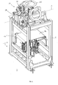
- the tire filling station 2 shown serves for the automated filling of a complete wheel 4, comprising a tire mounted on a rim, with a pressurized gas, here compressed air, within an industrial assembly line.
- a pressurized gas here compressed air
- the tire filling station 2 comprises a frame 6 in which a filling table or lifting table 10, which is adjustable in height, that is to say in the vertical direction, for example by means of a pneumatic cylinder 8 is arranged.
- a filling table or lifting table 10 which is adjustable in height, that is to say in the vertical direction, for example by means of a pneumatic cylinder 8 is arranged.
- the respective wheel / tire combination sometimes only referred to as a tire for the sake of simplicity, lies on the horizontally aligned support surface 12 of the lifting table 10 on.
- the complete wheel 4 is transferred into the filling position on the lifting table 10 in the conveying direction 14 by a conveyor device (not shown) and then transported further.
- the lifting table 10 itself can contain or have a conveyor device, for example in the form of a conveyor belt.
- the filling bell 16 comprises a filling bell lower part 18 with a filling ring 20 which is adapted to the size of the tire and which compresses the tire bead over the entire circumference during the lifting process.
- compressed air is fed into the tire via an associated compressed air supply to fill it.
- the arrangement is sealed during the filling process on the one hand on the underside of the tire by the support surface 12, on the other hand on the top of the tire by the filling bell upper part 22, which adjoins the filling bell lower part 18 with the filling ring 20 at the top.
- the lifting table 10 is again moves down to the starting position, whereby the annular gap in the tire closes automatically.
- a plurality of filling rings 20, here in the example six pieces, are kept ready, which are attached to a filling ring changer or ring changer for short.
- the ring changer comprises a carousel rotating device 24, also referred to as a revolver, which is fastened above the lifting table 10 to the frame 6 of the tire inflation station 2.
- the carousel rotating device 24 has an axis of rotation A that is perpendicular to the axis of the respective tire on the lifting table 10, namely horizontally, so that the filling ring holder 26, which is arranged axially symmetrically at the same distance from the axis of rotation A, with the filling rings 20 during a rotary movement of the carousel Rotary device 24 on a circular line (see FIG. 2 ) or the imaginary cylinder jacket surface around the filling bell upper part 22, which is fixedly attached to the frame 6.
- the axis of rotation A is the carousel rotating device 24 also aligned parallel to the conveying direction 14 of the tires, but this is not essential.
- the filling rings 20 are fastened to the carousel rotating device 24 by means of filling ring holders 26 in such a way that they (in the side plan view of FIG. 2 ) are aligned tangentially to the circular line. This results in a substantially hexagonal plan of the turret in the example.
- the carousel rotary device 24 can bring the appropriate filling ring 20 into the filling position in which it is positioned between the tire and the upper part of the filling bell with the filling ring axis aligned parallel to the tire axis 22 is arranged.
- the respective filling ring holder 26 with the filling ring 20 attached to it forms the filling bell lower part 18, which together with the filling bell upper part 22 forms the filling bell 16 as soon as both parts are in contact with one another.
- the carousel rotating device according to FIG. 3 and 4th
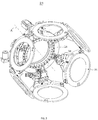
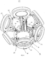
- a turntable 28 mounted perpendicular to the axis of rotation A with laterally protruding arms 30 which form or carry filler ring holders 26.
- the entirety of the turntable 28 and the filling ring holders 26 as well as the filling rings 20 fastened thereon lies within a substantially bowl-shaped outline.
- the opening area of this shell which is accessible from the outside from the side opposite the rotary disk 28 receives the filling bell upper part 22 and surrounds it in the area shown in FIG FIG. 1 and 2 installation position shown.
- On the turntable 28 there can be a toothed ring which is coupled to an electric drive, for example a servo drive, for setting the rotary position.
- the drive train can also be designed differently and z. B. include various gear elements. It is also conceivable to convert a linear movement caused by a linear drive into a rotary movement, for example by means of a rack.
- the revolver is preferably endlessly rotatable.
- the drive train can be designed to be self-locking. Additionally or alternatively, a lock can be provided which blocks the revolver during the filling process.
- a pneumatic cylinder also called an index cylinder 32
- a locking element such as a locking bolt 36
- the rotational position can be blocked as desired with a corresponding cylinder stroke of the index cylinder 32.
- a height adjustment for the filling bell upper part 22 is provided, for example by a pneumatic cylinder or another actuator. That is, the filling bell upper part 22 is moved vertically upwards a certain distance before the rotary movement in order to create the necessary freedom of movement. To initiate the filling process, the filling bell upper part 22 is moved back down to the lower end position, in which it rests on the filling ring holder 26 with the selected filling ring 20 while forming the filling bell 16 (see also FIG. 7th ).
- an adjustment of the radial distance between the filling ring holder 26 and the axis of rotation A of the revolver can be provided for the stated purpose.
- This can be done according to FIG. 6th be implemented for example by a rail guide 40 (slide rails) and associated pneumatic cylinders or servomotors or other actuators, which are each integrated in the arms 30 or suspensions carrying the filling ring holders 26, or by a corresponding adjustment mechanism in the filling ring holders 26 themselves integrated or independent of its existing spring mechanism with a corresponding spring deflection manages the compensation of tolerances.
- the respective filling ring holder 26 preferably comprises a retaining ring or carrier ring 44 fastened laterally to an arm 30, on the underside of which the associated filling ring 20 is exchangeably fastened, for example by means of a bayonet lock.
- the width of the carrier ring 44 is greater than that of the filling ring 20 in order to be able to accommodate filling rings 20 of different diameters.
- the carrier ring 44 receives an upwardly protruding sealing ring 46, for example in an annular groove on the top or on the inner edge, so that the sealing plate 48, which is lowered from above (see FIG FIG.
- the sealing plate 48 can be equipped with sealing means, in particular sealing rings or annular sealing zones, on its underside facing the carrier ring 44.
- the (spherical) suspension on the outer edge of the carrier ring 44 on the arm 30 is designed in such a way that it does not hinder the formation of the filling bell 16.
- the filling rings 20 are advantageously equipped with a writable RFID chip 50 (transponder).
- This chip contains important information such as B the diameter of the filler ring 20, the assigned rim size or the rim size range and / or other customer-specific data are stored.
- B the diameter of the filler ring 20, the assigned rim size or the rim size range and / or other customer-specific data are stored.
- an RFID reader 52 mounted on the filling bell upper part 22 reads out the data and sends them to a controller for the tire inflation station 2. In this way it can be checked and ensured that the filling ring 22 that matches the respective tire is actually in the current filling position.
- an optical or mechanically tactile coding of the filling rings 22 with corresponding sensoric detection can also be provided.
- the RFID coding is generally more robust and flexible.
- All filling rings 20 can be arranged on the turret with optimized cycle times.
- the arrangement of the filling rings 20 can be learned by turning the turret in the control software. This means that the control moves to all positions of the turret one after the other and reads the occupancy via the RFID data and saves them for use in subsequent control operations. One revolution of the turret after assignment is sufficient.
- a plurality of rod-like rim hold-down devices 56 can also be seen, which are passed through suitable recesses in the filling bell upper part 22, and which can be raised and lowered by associated actuators. In the lowered state, they press the rim of the complete wheel 4 lying on the lifting table 10 downwards. They also enable a tactile measurement of the rim.
- the preferred sequence of the filling process can be summarized as follows: First, the complete wheel 4 to be filled is conveyed into a centering station upstream of the tire inflation station 2. The complete wheel 4 is measured in the centering station, for example, with regard to the outer diameter of the tire and the inner diameter of the rim. The measurement data are fed to the control of the tire inflation station 2.
- the complete wheel 4 is now conveyed to the tire filling station 2 and placed on its lifting table 10, which is in the lowered position.
- the control determines the appropriate filling ring 20 and the angle of rotation of the revolver required for its selection.
- the locking bolt 36 must be pulled out of the position lock of the revolver by appropriate control of the index cylinder 32.
- the drive for the revolver is now released by the control and rotates the selected filling ring 20 into the filling position between the complete wheel 4 and the filling bell upper part 22. The rotational position of the revolver is then locked again by the locking bolt 36.
- the filling ring holder 26 with the filling ring 20 is now moved in the manner described above - by radial movement of the filling ring holder 26 inwards towards the axis of rotation A of the revolver and / or by lowering the filling bell upper part 22 - relative to the filling bell upper part 22, so that the complete Filling bell 26 forms.
- the controller uses the data ascertained by the RFID reader 52 to check that the desired filling ring 22 is actually in the filling position.
- the complete wheel 4 is now moved in the manner described above with the lifting table 10 up to the set filling ring 20 and filled with compressed air via the supply line connected to the filling bell upper part 22.
- the lifting table 10 is moved back to the lower end position and the complete wheel 4 is conveyed out of the tire filling station 2.
- the filling bell upper part 22 and the filling bell lower part 18 consisting of the filling ring holder 26 and the filling ring 20 are separated again in order to create space for the next turning process.
- the process described is repeated regularly every few seconds, for example every 5 to 10 seconds.
Landscapes
- Engineering & Computer Science (AREA)
- Mechanical Engineering (AREA)
- Filling Of Jars Or Cans And Processes For Cleaning And Sealing Jars (AREA)
- Moulds For Moulding Plastics Or The Like (AREA)
- Vehicle Body Suspensions (AREA)
- Superconductor Devices And Manufacturing Methods Thereof (AREA)
- External Artificial Organs (AREA)
Abstract
Description
- Die Erfindung betrifft eine Reifenfüllstation zum Füllen eines auf einer Felge angeordneten Reifens mit einem unter Druck stehenden Gas, insbesondere Druckluft. Dier Erfindung betrifft ferner ein Verfahren zum Betreiben einer Reifenfüllstation.
- Bei der automatischen Serienfertigung werden Kraftfahrzeugräder, sogenannte Kompletträder bestehend aus einer Radfelge und einem auf die Radfelge aufgebrachten Reifen, üblicherweise in einer in die Montagelinie integrierten automatischen Reifenfüllstation mit Druckluft befüllt. Die Felge mit montiertem Reifen wird hierbei auf eine geeignete Unterlageplatte gelegt, die das Rad beim Füllvorgang nach unten hin abdichtet. Auf die Reifenoberseite wird eine mit einem Füllring versehene Füllglocke aufgesetzt, die den Reifen und die Felge nach oben hin abdichtet, und durch welche die Reifenseitenwand beim Füllvorgang so weit nach unten gedrückt wird, dass zwischen Reifenwulst und Felge ein Ringspalt entsteht, durch den die in die Füllglocke geleitete Druckluft in den Reifen einströmen kann. Durch die eingeströmte Druckluft wird der Reifen mit großer Kraft gegen die Auflageplatte und die Füllglocke gepresst. Ist der Fülldruck erreicht, so wird die Füllglocke angehoben, wodurch sich die Reifenseitenwände in axialer Richtung auseinander bewegen, bis die Reifenwulste ihre jeweilige Sitzposition auf der Felge eingenommen haben.
- Für einen solchen Füllvorgang muss der Füllring der Füllglocke eine Öffnung haben, deren Durchmesser einerseits groß genug ist, damit die Füllglocke nicht an die Felge anstößt, sondern über die Felge gestülpt werden kann. Der Durchmesser der Öffnung darf andererseits aber nicht so groß sein, dass die Füllglocke die obere Reifenseitenwand radial außerhalb ihres Hochpunktes kontaktiert. Die Füllglocke würde nämlich dann die Radialbewegung des Reifens behindern, was dazu führen könnte, dass der Reifenwulst nicht richtig in seinen Sitz springt. Ein Füllring eines bestimmten Durchmessers eignet sich somit nur für einen begrenzten Größenbereich von Kraftfahrzeugrädern.
- Um den Größenbereich von in derselben Reifenfüllstation zu füllenden Reifen zu erweitern, weist eine aus
EP 1 671 820 B1 bekannte Reifenfüllstation eine Karussell-Dreheinrichtung mit einer parallel zur Achslinie der Rad-/ Reifenanordnung, nämlich vertikal ausgerichteten Drehachse auf, an deren Umfang mehrere Füllringe unterschiedlichen Durchmessers angeordnet sind. Die Füllringe liegen allesamt in einer horizontalen Ebene. Durch die Anwahl einer geeigneten Drehstellung der Karussell-Dreheinrichtung wird ein Füllring mit geeignetem Durchmesser in einer quer zur Achslinie verlaufenden seitlichen Bewegung über den zu füllenden Reifen geschwenkt und bildet dann zusammen mit einer zugehörigen Füllplatte eine Füllglocke für den Füllvorgang. - Nachteilig an dieser Reifenfüllstation ist die relativ große seitliche Ausdehnung der Karussell-Dreheinrichtung, die einen großen Aufstellungsraum benötigt. Dies erschwert auch die Aufstellung von Schallschutzwänden um die Reifenfüllstation herum.
- Aufgabe der Erfindung ist, es eine kompakte Reifenfüllstation der angegebenen Art zu schaffen, die für einen großen Bereich verschiedener Reifengrößen geeignet und kostengünstig herstellbar ist. Die Reifenfüllstation soll eine hohe Füllgenauigkeit ermöglichen und zuverlässig und wartungsarm sein. Es ist weiterhin Aufgabe der Erfindung, ein vorteilhaftes Verfahren zum Betreiben einer Reifenfüllstation anzugeben.
- Die Aufgabe wird erfindungsgemäß gelöst hinsichtlich der Reifenfüllstation durch die in Anspruch 1 angegebenen Merkmale und hinsichtlich des Verfahrens durch die in Anspruch 9 angegebenen Verfahrensschritte.
- Vorteilhafte Ausgestaltungen der Reifenfüllstation sind in den abhängigen Ansprüchen 2 bis 8 angegeben.
- Nach der Erfindung ist eine Reifenfüllstation vorgesehen mit
- einem zu einem Füllglockenoberteil hin bewegbaren Hubtisch für einen zu befüllenden Reifen, wobei das Füllglockenoberteil oberhalb des Hubtisches angeordnet ist, und
- einer um eine horizontale Drehachse drehbaren Karussell-Dreheinrichtung mit einer Mehrzahl von umfänglich an ihr angeordneten oder befestigbaren Füllringen, die jeweils durch entsprechende Drehung der Karussell-Dreheinrichtung zur Ausbildung einer Füllglocke in eine Füllposition zwischen dem Reifen und dem Füllglockenoberteil bewegbar sind.
- Die Karussell-Dreheinrichtung wird auch als Revolver bezeichnet.
- Das entsprechende Verfahren ist analog definiert.
- Die mit der Erfindung erzielten Vorteile bestehen insbesondere darin, dass durch eine einfache Drehbewegung des Revolvers um eine horizontale Drehachse oberhalb des Hubtisches eine hohe Flexibilität hinsichtlich der verwendbaren Füllringe erreicht wird. Dies ermöglicht insbesondere ein besseres Handling bei Sondergrößen. Die Reifenfüllstation ist dabei in ihrer lateralen Ausdehnung besonders kompakt, bei zugleich guter Zugänglichkeit bei Wartungsarbeiten und dergleichen. Durch die zusätzliche Hinterlegung von RFID Daten an den Füllringen und deren Erfassung und Berücksichtigung bei der Anlagensteuerung lässt sich eine hohe betriebliche Sicherheit, ohne die Gefahr von Verwechslungen, bei zugleich optimierter Taktzeit erreichen.
- Weitere Ausgestaltungen der Erfindung und damit erzielte Vorteile sind Gegenstand der anhängigen Ansprüche sowie der detaillierten Beschreibung.
- Die Erfindung wird nachfolgend anhand eines Ausführungsbeispiels näher erläutert, das in den Zeichnungen dargestellt ist. Es zeigen:
- FIG. 1
- eine perspektivische Ansicht einer Reifenfüllstation nach der Erfindung,
- FIG. 2
- eine Seitenansicht der Reifenfüllstation gemäß
FIG. 1 , - FIG. 3
- eine erste perspektivische Ansicht einer Karussell-Dreheinrichtung der Reifenfüllstation gemäß
Fig. 1 , - FIG. 4
- eine zweite perspektivische Ansicht der Karussell-Dreheinrichtung gemäß
FIG. 3 , hier zusammen mit einem Füllglockenoberteil und weiteren Komponenten, - FIG. 5
- ein Detail aus
FIG. 1 mit einer Verriegelung für die Karussell-Dreheinrichtung, - FIG. 6
- eine perspektivische Ansicht eines an der Karussell-Dreheinrichtung gemäß
FIG. 3 befestigten Füllringhalters mit einem zugehörigen Füllring, und - FIG. 7
- eine perspektivische Detailansicht einer Füllglocke der Reifenfüllstation gemäß
FIG. 1 . - Gleiche oder funktionsgleiche Elemente sind in allen Figuren mit denselben Bezugszeichen versehen.
- Die in
FIG. 1 und2 dargestellte Reifenfüllstation 2 dient zur automatisierten Befüllung eines Komplettrades 4, umfassend einen auf einer Felge aufgezogenen Reifen, mit einem unter Druck stehenden Gas, hier Druckluft, innerhalb einer industriellen Montagelinie. - Die Reifenfüllstation 2 umfasst einen Rahmen 6, in dem ein beispielsweise mittels eines Pneumatikzylinders 8 in seiner Höhe, also in vertikaler Richtung, verstellbarer Fülltisch oder Hubtisch 10 angeordnet ist. Während des Füllvorgangs liegt die jeweilige Rad-/ Reifenkombination, der Einfachheit halber bisweilen nur als Reifen bezeichnet, auf der horizontal ausgerichteten Auflagefläche 12 des Hubtisches 10 auf. Das Komplettrad 4 wird vor dem Füllvorgang durch eine nicht dargestellte Fördereinrichtung in Förderrichtung 14 in die Füllposition auf dem Hubtisch 10 überführt und anschließend weiter transportiert. Der Hubtisch 10 kann zu diesem Zweck selbst eine Fördereinrichtung, beispielswiese in Gestalt eines Förderbandes, beinhalten oder aufweisen.
- Zur Befüllung mit Druckluft wird der auf dem Hubtisch 10 liegende Reifen durch einen Hub des Hubtisches 10 nach oben gegen eine in
FIG. 1 und2 durch den Rahmen 6 verdeckte, jedoch inFIG. 4 und7 gut sichtbare Füllglocke 16 gedrückt. Die Füllglocke 16 umfasst ein Füllglockenunterteil 18 mit einem an die Größe des Reifens angepassten Füllring 20, der den Reifenwulst während des Hubvorgangs über den kompletten Umfang hinweg zusammendrückt. In den so entstehenden Ringspalt wird über eine zugehörige Druckluft-Zuführung Druckluft in den Reifen zu dessen Befüllung eingeleitet. Eine Abdichtung der Anordnung erfolgt während des Füllvorgangs einerseits an der Unterseite des Reifens durch die Auflagefläche 12, andererseits an der Oberseite des Reifens durch das sich oben an das Füllglockenunterteil 18 mit dem Füllring 20 anschließende Füllglockenoberteil 22. Nach Beendigung des Füllvorgangs wird der Hubtisch 10 wieder nach unten in die Ausgangsposition bewegt, wobei sich der Ringspalt im Reifen automatisch verschließt. - Für eine Anpassung an unterschiedliche Reifengrößen wird eine Mehrzahl von Füllringen 20, hier im Beispiel sechs Stück, bereitgehalten, die an einem Füllringwechsler oder kurz Ringwechsler befestigt sind. Der Ringwechsler umfasst eine auch als Revolver bezeichnete Karussell-Dreheinrichtung 24, welche oberhalb des Hubtisches 10 an dem Rahmen 6 der Reifenfüllstation 2 befestigt ist. Die Karussell-Dreheinrichtung 24 weist eine senkrecht zur Achse des jeweiligen Reifens auf dem Hubtisch 10, nämlich horizontal ausgerichtete Drehachse A auf, so dass sich die achssymmetrisch in jeweils gleichem Abstand zur Drehachse A angeordneten Füllringhalter 26 mit den Füllringen 20 während einer Drehbewegung der Karussell-Dreheinrichtung 24 auf einer Kreislinie (siehe
FIG. 2 ) oder gedachten Zylindermantelfläche um das stationär am Rahmen 6 befestigte Füllglockenoberteil 22 herum bewegen. Im vorliegenden Beispiel ist die Drehachse A der Karussell-Dreheinrichtung 24 zudem parallel zur Förderrichtung 14 der Reifen ausgerichtet, aber dies ist nicht zwingend. Die Füllringe 20 sind mittels Füllringhaltern 26 derart an der Karussell-Dreheinrichtung 24 befestigt, dass sie (in der seitlichen Draufsicht vonFIG. 2 ) tangential zu der Kreislinie ausgerichtet sind. Dadurch ergibt sich im Beispiel ein im Wesentlichen sechseckförmiger Grundriss des Revolvers. - Selbstverständlich können bei entsprechender Größe des Revolvers auch mehr oder weniger als sechs Füllringe 20 an selbigem angebracht sein.
- Auf diese Weise lässt sich durch geeignete Wahl der Drehstellung, hier im Beispiel in 60°-Schritten, der Karussell-Dreheinrichtung 24 der jeweils passende Füllring 20 in die Füllposition bringen, in der er mit parallel zur Reifenachse ausgerichteter Füllringachse zwischen dem Reifen und dem Füllglockenoberteil 22 angeordnet ist. Der jeweilige Füllringhalter 26 mit dem an ihm befestigten Füllring 20 bildet das Füllglockenunterteil 18, welches zusammen mit dem Füllglockenoberteil 22 die Füllglocke 16 bildet, sobald beide Teile aneinander anliegen.
- Konkret umfasst die Karussell-Dreheinrichtung gemäß
FIG. 3 und4 im dargestellten Beispiel eine senkrecht zur Drehachse A montierte Drehscheibe 28 mit seitlich abstehenden Armen 30, welche Füllringhalter 26 ausbilden oder tragen. Die Gesamtheit aus Drehscheibe 28 und Füllringhaltern 26 sowie daran befestigten Füllringen 20 liegt innerhalb eines im Wesentlichen schalenförmigen Umrisses. Der von der der Drehscheibe 28 gegenüberliegenden Seite von außen zugängliche Öffnungsbereich dieser Schale nimmt das Füllglockenoberteil 22 auf und umgibt es in der inFIG. 1 und2 dargestellten Einbaulage. An der Drehscheibe 28 kann sich ein Zahnkranz befinden, der mit einem elektrischen Antrieb, beispielsweise einem Servoantrieb zur Einstellung der Drehstellung gekoppelt ist. Im Detail kann der Antriebsstrang auch anders ausgestaltet sein und z. B. verschiedene Getriebeelemente umfassen. Es ist auch eine Umsetzung einer von einem Linearantrieb verursachten Linearbewegung in eine Drehbewegung denkbar, etwa mittels einer Zahnstange. Der Revolver ist bevorzugt endlos drehbar. - Um die Karussell-Drehvorrichtung 24 während des Füllvorgangs sicher in der gewünschten Drehstellung zu fixieren, kann der Antriebsstrang selbsthemmend ausgeführt sein. Zusätzlich oder alternativ kann eine Verriegelung vorgesehen sein, die während des Füllvorganges den Revolver blockiert. Eine in
FIG. 5 dargestellte mögliche Lösung umfasst einen am Rahmen 6 angebrachten Pneumatikzylinder, auch Indexzylinder 32 genannt, an dessen Hubstange ein zum Eingriff in zugehörige Indexbohrungen 34 oder -öffnungen in der Drehscheibe 28 vorgesehenes Verriegelungselement, etwa ein Verriegelungsbolzen 36 angebracht ist. Durch den zumindest teilweise formschlüssigen Eingriff lässt sich die Drehstellung bei entsprechendem Zylinderhub des Indexzylinders 32 wie gewünscht blockieren. - Damit die Füllringhalter 26 während der Drehbewegung des Revolvers genügend Platz haben und nicht an dem Füllglockenoberteil 22 anschlagen oder hängenbleiben, ist in einer möglichen Variante eine beispielsweise durch einen Pneumatikzylinder oder durch einen anderen Aktor bewirkte Höhenverstellung für das Füllglockenoberteil 22 vorhanden. Das heißt, das Füllglockenoberteil 22 wird vor der Drehbewegung eine gewisse Wegstrecke vertikal nach oben bewegt, um den erforderlichen Bewegungsspielraum zu schaffen. Zur Einleitung des Füllvorganges wird das Füllglockenoberteil 22 wieder nach unten in die untere Endlage gefahren, in der es unter Ausbildung der Füllglocke 16 auf dem Füllringhalter 26 mit dem gewählten Füllring 20 aufliegt (siehe auch
FIG. 7 ). - Alternativ oder zusätzlich kann zu dem genannten Zweck eine Verstellung des radialen Abstandes der Füllringhalter 26 zur Drehachse A des Revolvers vorgesehen sein. Dies kann gemäß
FIG. 6 beispielsweise durch eine Schienenführung 40 (Gleitschienen) und zugehörige Pneumatikzylinder oder Servomotoren oder andere Aktoren verwirklicht sein, die jeweils in die die Füllringhalter 26 tragenden Arme 30 oder Aufhängungen integriert sind, oder durch eine entsprechende Verstellmechanik in den Füllringhaltern 26 selbst. Eine beispielsweise in die Verstellung integrierte oder unabhängig von ihr vorhandene Federmechanik mit einem entsprechenden Federweg bewerkstelligt den Ausgleich von Toleranzen. - Wie in
FIG. 6 dargestellt, umfasst der jeweilige Füllringhalter 26 vorzugsweise einen seitlich an einem Arm 30 befestigten Haltering oder Trägerring 44, an dessen Unterseite der zugehörige Füllring 20 auswechselbar befestigt ist, beispielsweise mittels eines Bajonettverschlusses. Die Breite des Trägerrings 44 ist größer als die des Füllrings 20, um Füllringe 20 verschiedenen Durchmessers aufnehmen zu können. Der Trägerring 44 nimmt beispielsweise in einer Ringnut an der Oberseite oder am Innenrand einen nach oben abstehenden Dichtring 46 auf, so sich der von oben absenkende Dichtteller 48 (sieheFIG. 4 ), auch Dichtplatte genannt, des Füllglockenoberteils 22 während des Füllvorgangs spalt- und leckagefrei an den Trägerring 44 anlegen kann. Alternativ oder zusätzlich kann der Dichtteller 48 an seiner dem Trägerring 44 zugewandten Unterseite mit Dichtmitteln, insbesondere Dichtringen oder ringförmigen Dichtzonen, ausgestattet sein. Die (sphärische) Aufhängung am äußeren Rand des Trägerrings 44 am Arm 30 ist so gestaltet, dass sie die Ausbildung der Füllglocke 16 nicht behindert. - Die Füllringe 20 sind vorteilhafterweise mit mit einem beschreibbaren RFID Chip 50 (Transponder) ausgestattet. In diesem Chip sind wichtige Informationen wie z. B der Durchmesser des Füllrings 20, die zugordnete Felgengröße bzw. der Felgengrößenbereich und/oder andere kundenspezifische Daten hinterlegt. Ein gemäß
FIG. 7 beispielsweise am Füllglockenoberteil 22 montiertes RFID Lesegerät 52 (Sensor oder Empfänger) liest die Daten aus und führt sie einer Steuerung für die Reifenfüllstation 2 zu. Auf diese Weise kann überprüft und sichergestellt werden, dass tatsächlich der zum jeweiligen Reifen passende Füllring 22 sich in der aktuellen Füllstellung befindet. - Anstelle der RFID-Technologie kann auch eine optische oder mechanisch ertastbare Codierung der Füllringe 22 mit entsprechender sensorischer Erfassung vorgesehen sein. Die RFID Codierung ist aber im Allgemeinen robuster und flexibler.
- Alle Füllringe 20 können am Revolver taktzeitoptimiert angeordnet werden. Die Anordnung der Füllringe 20 kann über eine Revolverumdrehung in der Software der Steuerung angelernt werden. Das heißt, die Steuerung fährt nacheinander alle Plätze des Revolvers an und liest die Belegung über die RFID Daten aus und speichert sie zur Benutzung bei den nachfolgenden Steuervorgängen. Eine Revolverumdrehung nach Belegung genügt hierzu.
- In
FIG. 4 sind auch mehrere stangenartige Felgenniederhalter 56 erkennbar, die durch geeignete Ausnehmungen im Füllglockenoberteil 22 hindurchgeführt sind, und die durch zugehordnete Aktoren angehoben und abgesenkt werden können. Im abgesenkten Zustand drücken sie die Felge des auf dem Hubtisch 10 liegenden Komplettrades 4 nach unten. Sie ermöglichen auch eine taktile Vermessung der Felge. - Der bevorzugte Ablauf des Füllvorganges lässt sich wie wie folgt zusammenfassen:
Zunächst wird das zu befüllende Komplettrad 4 in eine der Reifenfüllstation 2 vorgelagerte Zentrierstation gefördert. Das Komplettrad 4 wird in der Zentrierstation beispielsweise hinsichtlich des Außendurchmessers des Reifens und des Innendurchmessers der Felge vermessen. Die Messdaten werden der Steuerung der Reifenfüllstation 2 zugeführt. - Das Komplettrad 4 wird nun in die Reifenfüllstation 2 gefördert und auf dessen in abgesenkter Position befindlichen Hubtisch 10 abgelegt. Die Steuerung ermittelt anhand der zuvor ermittelten oder einprogrammierten Belegung des Revolvers den passenden Füllring 20 und den zu seiner Auswahl erforderlichen Drehwinkel des Revolvers. Vor der Drehung muss der Verriegelungsbolzen 36 durch entsprechende Ansteuerung des Indexzylinders 32 aus der Lagesicherung des Revolvers herausgezogen werden. Der Antrieb für den Revolver bekommt nun von der Steuerung die Freigabe und dreht den ausgewählten Füllring 20 in die Füllposition zwischen dem Komplettrad 4 und dem Füllglockenoberteil 22. Anschließend wird die Drehstellung des Revolvers wieder durch den Verriegelungsbolzen 36 arretiert. Der Füllringhalter 26 mit dem Füllring 20 wird nun in der oben beschrieben Weise - durch Radialbewegung des Füllringhalters 26 nach innen hin zur Drehhachse A des Revolvers und/oder durch Absenkung des Füllglockenoberteils 22 - relativ zum Füllglockenoberteil 22 zu selbigem hinbewegt, so dass sich die komplette Füllglocke 26 ausbildet. Sicherheitshalber überprüft die Steuerung anhand der von RFID Lesegerät 52 ermittelten Daten, dass tatsächlich der gewünschte Füllring 22 sich in der Füllposition befindet.
- Das Komplettrad 4 wird nun in der eingangs geschilderten Weise mit dem Hubtisch 10 nach oben an den eingestellten Füllring 20 in Position gefahren und mit Druckluft über die an das Füllglockenoberteil 22 angeschlossene Zufuhrleitung gefüllt.
- Nach dem Füllvorgang wird der Hubtisch 10 wieder in die untere Endlage gefahren und das Komplettrad 4 aus der Reifenfüllstation 2 gefördert. Das Füllglockenoberteil 22 und das aus Füllringhalter 26 und Füllring 20 bestehende Füllglockenunterteil 18 werden wieder separiert, um Platz für den nächsten Drehvorgang zu schaffen.
- Der beschriebene Vorgang wiederholt sich regelmäßig alle paar Sekunden, beispielsweise alle 5 bis 10 Sekunden.
-
- 2
- Reifenfüllstation
- 4
- Komplettrad / Reifen
- 6
- Rahmen
- 8
- Pneumatikzylinder
- 10
- Hubtisch
- 12
- Auflagefläche
- 14
- Förderrichtung
- 16
- Füllglocke
- 18
- Füllglockenunterteil
- 20
- Füllring
- 22
- Füllglockenoberteil
- 24
- Karussell-Dreheinrichtung (Revolver)
- 26
- Füllringhalter
- 28
- Drehscheibe
- 30
- Arm
- 32
- Indexzylinder
- 34
- Indexbohrung
- 36
- Verriegelungsbolzen
- 40
- Schienenführung
- 44
- Trägerring
- 46
- Dichtring
- 48
- Dichtteller
- 50
- RFID Chip
- 52
- RFID Lesegerät
- 56
- Felgenniederhalter
- A
- Drehachse
Claims (9)
- Reifenfüllstation (2) mit• einem zu einem Füllglockenoberteil (22) hin bewegbaren Hubtisch (10) für einen zu befüllenden Reifen, wobei das Füllglockenoberteil (22) oberhalb des Hubtisches (10) angeordnet ist, und• einer um eine horizontale Drehachse (A) drehbaren Karussell-Dreheinrichtung (24) mit einer Mehrzahl von umfänglich an ihr befestigbaren Füllringen (20), die jeweils durch entsprechende Drehung der Karussell-Dreheinrichtung (24) zur Ausbildung einer Füllglocke (16) in eine Füllposition zwischen dem Reifen und dem Füllglockenoberteil (22) bewegbar sind.
- Reifenfüllstation (2) nach Anspruch 1, wobei die Karussell-Dreheinrichtung (24) oberhalb des Hubtisches (10) angeordnet ist.
- Reifenfüllstation (2) nach Anspruch 2, wobei die Karussell-Dreheinrichtung (24) das Füllglockenoberteil (22) zumindest teilweise umschließt.
- Reifenfüllstation (2) nach einem der vorangehenden Ansprüche, wobei die Drehstellung der Karussell-Dreheinrichtung (24) durch eine Verriegelung blockierbar ist.
- Reifenfüllstation (2) nach einem der vorangehenden Ansprüche, wobei die Karussell-Dreheinrichtung (24) eine Drehscheibe (28) mit seitlich abstehenden Armen (30) aufweist, welche jeweils einen Füllringhalter (26) tragen.
- Reifenfüllstation (2) nach Anspruch 5, wobei der jeweilige Füllring (20) auswechselbar, vorzugsweise mittels Bajonettverschluss, am Füllringhalter (26) befestigt ist.
- Reifenfüllstation (2) nach Anspruch 5 oder 6, wobei in der Füllposition der radiale Abstand zwischen dem Füllringhalter (26) und der Drehachse (A) der Karussell-Dreheinrichtung (24) durch einen Aktor veränderbar ist.
- Reifenfüllstation (2) nach einem der vorangehenden Ansprüche, wobei der jeweilige Füllring (20) eine RFID Codierung aufweist, und wobei eine zugehörige Steuerung die Codierung sensorisch erfasst und bei der Steuerung der Reifenfüllstation (2) berücksichtigt.
- Verfahren zum Betrieben einer Reifenfüllstation (2) mit einem zu einem Füllglockenoberteil (22) hin bewegbaren Hubtisch (10) für einen zu befüllenden Reifen, wobei das Füllglockenoberteil (22) oberhalb des Hubtisches (10) angeordnet ist, und wobei durch entsprechende Drehung einer um eine horizontale Drehachse (A) drehbaren Karussell-Dreheinrichtung (24) mit einer Mehrzahl von umfänglich an ihr befestigbaren Füllringen (20) einer der Füllringe (22) zur Ausbildung einer Füllglocke (16) in eine Füllposition zwischen dem Reifen und dem Füllglockenoberteil (22) bewegt wird.
Applications Claiming Priority (1)
| Application Number | Priority Date | Filing Date | Title |
|---|---|---|---|
| DE102019109497.6A DE102019109497A1 (de) | 2019-04-10 | 2019-04-10 | Reifenfüllstation und zugehöriges Betriebsverfahren |
Publications (2)
| Publication Number | Publication Date |
|---|---|
| EP3722115A1 true EP3722115A1 (de) | 2020-10-14 |
| EP3722115B1 EP3722115B1 (de) | 2022-04-06 |
Family
ID=69526185
Family Applications (1)
| Application Number | Title | Priority Date | Filing Date |
|---|---|---|---|
| EP20156072.9A Active EP3722115B1 (de) | 2019-04-10 | 2020-02-07 | Reifenfüllstation und zugehöriges betriebsverfahren |
Country Status (4)
| Country | Link |
|---|---|
| EP (1) | EP3722115B1 (de) |
| DE (1) | DE102019109497A1 (de) |
| ES (1) | ES2920848T3 (de) |
| PT (1) | PT3722115T (de) |
Cited By (1)
| Publication number | Priority date | Publication date | Assignee | Title |
|---|---|---|---|---|
| CN114623375A (zh) * | 2022-03-25 | 2022-06-14 | 北京博联众睿机器人科技有限公司 | 球形罐自动化充气设备 |
Families Citing this family (1)
| Publication number | Priority date | Publication date | Assignee | Title |
|---|---|---|---|---|
| IT202100022520A1 (it) * | 2021-08-30 | 2023-03-02 | Mo S A I C Motion System And Information Control S R L | Stazione di gonfiaggio pneumatici |
Citations (2)
| Publication number | Priority date | Publication date | Assignee | Title |
|---|---|---|---|---|
| WO2009155503A2 (en) * | 2008-06-20 | 2009-12-23 | Android Industries Llc | Vertical stack presenter for presenting inflator ring |
| EP1671820B1 (de) | 2004-12-20 | 2012-05-30 | Schenck RoTec GmbH | Reifenfüllstation und Verfahren zur Reifenfüllung |
Family Cites Families (3)
| Publication number | Priority date | Publication date | Assignee | Title |
|---|---|---|---|---|
| DE102009046195B3 (de) * | 2009-10-30 | 2011-03-17 | Schenck Rotec Gmbh | Reifenfüllstation und Verfahren zum Füllen von Reifen |
| US8770236B2 (en) * | 2009-11-20 | 2014-07-08 | Android Industries Llc | Inflator apparatus, system and method for utilizing the same |
| DE102013104007A1 (de) * | 2013-04-19 | 2014-10-23 | Schenck Rotec Gmbh | Reifenfüllvorrichtung |
-
2019
- 2019-04-10 DE DE102019109497.6A patent/DE102019109497A1/de not_active Withdrawn
-
2020
- 2020-02-07 EP EP20156072.9A patent/EP3722115B1/de active Active
- 2020-02-07 ES ES20156072T patent/ES2920848T3/es active Active
- 2020-02-07 PT PT201560729T patent/PT3722115T/pt unknown
Patent Citations (2)
| Publication number | Priority date | Publication date | Assignee | Title |
|---|---|---|---|---|
| EP1671820B1 (de) | 2004-12-20 | 2012-05-30 | Schenck RoTec GmbH | Reifenfüllstation und Verfahren zur Reifenfüllung |
| WO2009155503A2 (en) * | 2008-06-20 | 2009-12-23 | Android Industries Llc | Vertical stack presenter for presenting inflator ring |
Cited By (1)
| Publication number | Priority date | Publication date | Assignee | Title |
|---|---|---|---|---|
| CN114623375A (zh) * | 2022-03-25 | 2022-06-14 | 北京博联众睿机器人科技有限公司 | 球形罐自动化充气设备 |
Also Published As
| Publication number | Publication date |
|---|---|
| PT3722115T (pt) | 2022-07-04 |
| EP3722115B1 (de) | 2022-04-06 |
| ES2920848T3 (es) | 2022-08-10 |
| DE102019109497A1 (de) | 2020-10-15 |
Similar Documents
| Publication | Publication Date | Title |
|---|---|---|
| EP2388155B1 (de) | Vorrichtung und Verfahren zur Änderung der Drehwinkellage eines Luftreifens auf einer Felge | |
| DE102009046195B3 (de) | Reifenfüllstation und Verfahren zum Füllen von Reifen | |
| EP2514611B1 (de) | Verfahren und Vorrichtung zur Montage eines Luftreifens mit Hilfe eines Roboters | |
| EP1671820B1 (de) | Reifenfüllstation und Verfahren zur Reifenfüllung | |
| EP2258623B1 (de) | Vorrichtung und Verfahren zur Behandlung von Behältern | |
| EP1125772B2 (de) | Reifenfüllstation und Verfahren zur Reifenfüllung | |
| EP3446816B1 (de) | Spannfutter für räder | |
| EP2792511B1 (de) | Reifenfüllvorrichtung | |
| DE69604799T2 (de) | Gerät und verfahren zum anbringen von reifenwülsten | |
| EP3682981B1 (de) | Verfahren und vorrichtung zum drückwalzen | |
| EP3722115B1 (de) | Reifenfüllstation und zugehöriges betriebsverfahren | |
| DE1579288B1 (de) | Vorrichtung zum Einbringen eines Reifenrohlings in eine mit dem unteren Formteil einer Form- und Vulkanisierpresse fuer Luftreifen ausgerichtete Lage | |
| DE202009012532U1 (de) | Wechselsystem für Behälter | |
| EP3209990B1 (de) | Prüfvorrichtung für eine reifenfüllvorrichtung | |
| EP0792761B1 (de) | Vorrichtung zur Verbesserung des Laufverhaltens von Fahrzeugrädern durch Verbesserung des Sitzes der Wulstpartien auf der Felge | |
| EP1738937B1 (de) | Verfahren und Vorrichtung zur Montage eines Luftreifens | |
| EP4116256B1 (de) | Vorrichtung zum zuführen eines behälterverschlusses und verschliessvorrichtung | |
| DE69400853T2 (de) | Maschine zum Aufbringen von Kapseln auf Flaschen mit Gummistopfen | |
| EP1110765B1 (de) | Reifenfüllstation zum Füllen eines Rades mit Druckluft sowie Verfahren hierfür | |
| DE98524T1 (de) | Ladevorrichtung fuer reifen. | |
| DE3918209C2 (de) | Vorrichtung zum Beschicken einer Reifenheizpresse | |
| DE102017205413A1 (de) | Verfahren zur Typisierung eines Fahrzeugreifens und Fertigungsanlage zur Durchführung des Verfahrens | |
| EP1362717A2 (de) | Verfahren und Vorrichtung zum Montieren eines Luftreifens auf eine Felge eines Kraftfahrzeugrades | |
| DE3546183C2 (de) | Vorrichtung zum fuellen schlauchloser auf felgen aufgezogener reifen | |
| DE69613301T2 (de) | Reifenfüllgerät |
Legal Events
| Date | Code | Title | Description |
|---|---|---|---|
| PUAI | Public reference made under article 153(3) epc to a published international application that has entered the european phase |
Free format text: ORIGINAL CODE: 0009012 |
|
| STAA | Information on the status of an ep patent application or granted ep patent |
Free format text: STATUS: THE APPLICATION HAS BEEN PUBLISHED |
|
| AK | Designated contracting states |
Kind code of ref document: A1 Designated state(s): AL AT BE BG CH CY CZ DE DK EE ES FI FR GB GR HR HU IE IS IT LI LT LU LV MC MK MT NL NO PL PT RO RS SE SI SK SM TR |
|
| AX | Request for extension of the european patent |
Extension state: BA ME |
|
| STAA | Information on the status of an ep patent application or granted ep patent |
Free format text: STATUS: REQUEST FOR EXAMINATION WAS MADE |
|
| 17P | Request for examination filed |
Effective date: 20210121 |
|
| RBV | Designated contracting states (corrected) |
Designated state(s): AL AT BE BG CH CY CZ DE DK EE ES FI FR GB GR HR HU IE IS IT LI LT LU LV MC MK MT NL NO PL PT RO RS SE SI SK SM TR |
|
| GRAP | Despatch of communication of intention to grant a patent |
Free format text: ORIGINAL CODE: EPIDOSNIGR1 |
|
| STAA | Information on the status of an ep patent application or granted ep patent |
Free format text: STATUS: GRANT OF PATENT IS INTENDED |
|
| INTG | Intention to grant announced |
Effective date: 20210913 |
|
| GRAS | Grant fee paid |
Free format text: ORIGINAL CODE: EPIDOSNIGR3 |
|
| GRAA | (expected) grant |
Free format text: ORIGINAL CODE: 0009210 |
|
| STAA | Information on the status of an ep patent application or granted ep patent |
Free format text: STATUS: THE PATENT HAS BEEN GRANTED |
|
| AK | Designated contracting states |
Kind code of ref document: B1 Designated state(s): AL AT BE BG CH CY CZ DE DK EE ES FI FR GB GR HR HU IE IS IT LI LT LU LV MC MK MT NL NO PL PT RO RS SE SI SK SM TR |
|
| REG | Reference to a national code |
Ref country code: GB Ref legal event code: FG4D Free format text: NOT ENGLISH |
|
| REG | Reference to a national code |
Ref country code: CH Ref legal event code: EP |
|
| REG | Reference to a national code |
Ref country code: AT Ref legal event code: REF Ref document number: 1481005 Country of ref document: AT Kind code of ref document: T Effective date: 20220415 |
|
| REG | Reference to a national code |
Ref country code: DE Ref legal event code: R096 Ref document number: 502020000883 Country of ref document: DE |
|
| REG | Reference to a national code |
Ref country code: IE Ref legal event code: FG4D Free format text: LANGUAGE OF EP DOCUMENT: GERMAN |
|
| REG | Reference to a national code |
Ref country code: FI Ref legal event code: FGE |
|
| REG | Reference to a national code |
Ref country code: PT Ref legal event code: SC4A Ref document number: 3722115 Country of ref document: PT Date of ref document: 20220704 Kind code of ref document: T Free format text: AVAILABILITY OF NATIONAL TRANSLATION Effective date: 20220627 |
|
| REG | Reference to a national code |
Ref country code: NL Ref legal event code: FP |
|
| REG | Reference to a national code |
Ref country code: SE Ref legal event code: TRGR |
|
| REG | Reference to a national code |
Ref country code: LT Ref legal event code: MG9D |
|
| REG | Reference to a national code |
Ref country code: ES Ref legal event code: FG2A Ref document number: 2920848 Country of ref document: ES Kind code of ref document: T3 Effective date: 20220810 |
|
| PG25 | Lapsed in a contracting state [announced via postgrant information from national office to epo] |
Ref country code: NO Free format text: LAPSE BECAUSE OF FAILURE TO SUBMIT A TRANSLATION OF THE DESCRIPTION OR TO PAY THE FEE WITHIN THE PRESCRIBED TIME-LIMIT Effective date: 20220706 Ref country code: LT Free format text: LAPSE BECAUSE OF FAILURE TO SUBMIT A TRANSLATION OF THE DESCRIPTION OR TO PAY THE FEE WITHIN THE PRESCRIBED TIME-LIMIT Effective date: 20220406 Ref country code: HR Free format text: LAPSE BECAUSE OF FAILURE TO SUBMIT A TRANSLATION OF THE DESCRIPTION OR TO PAY THE FEE WITHIN THE PRESCRIBED TIME-LIMIT Effective date: 20220406 Ref country code: GR Free format text: LAPSE BECAUSE OF FAILURE TO SUBMIT A TRANSLATION OF THE DESCRIPTION OR TO PAY THE FEE WITHIN THE PRESCRIBED TIME-LIMIT Effective date: 20220707 Ref country code: BG Free format text: LAPSE BECAUSE OF FAILURE TO SUBMIT A TRANSLATION OF THE DESCRIPTION OR TO PAY THE FEE WITHIN THE PRESCRIBED TIME-LIMIT Effective date: 20220706 |
|
| PG25 | Lapsed in a contracting state [announced via postgrant information from national office to epo] |
Ref country code: RS Free format text: LAPSE BECAUSE OF FAILURE TO SUBMIT A TRANSLATION OF THE DESCRIPTION OR TO PAY THE FEE WITHIN THE PRESCRIBED TIME-LIMIT Effective date: 20220406 Ref country code: PL Free format text: LAPSE BECAUSE OF FAILURE TO SUBMIT A TRANSLATION OF THE DESCRIPTION OR TO PAY THE FEE WITHIN THE PRESCRIBED TIME-LIMIT Effective date: 20220406 Ref country code: LV Free format text: LAPSE BECAUSE OF FAILURE TO SUBMIT A TRANSLATION OF THE DESCRIPTION OR TO PAY THE FEE WITHIN THE PRESCRIBED TIME-LIMIT Effective date: 20220406 Ref country code: IS Free format text: LAPSE BECAUSE OF FAILURE TO SUBMIT A TRANSLATION OF THE DESCRIPTION OR TO PAY THE FEE WITHIN THE PRESCRIBED TIME-LIMIT Effective date: 20220806 |
|
| REG | Reference to a national code |
Ref country code: DE Ref legal event code: R097 Ref document number: 502020000883 Country of ref document: DE |
|
| PG25 | Lapsed in a contracting state [announced via postgrant information from national office to epo] |
Ref country code: SM Free format text: LAPSE BECAUSE OF FAILURE TO SUBMIT A TRANSLATION OF THE DESCRIPTION OR TO PAY THE FEE WITHIN THE PRESCRIBED TIME-LIMIT Effective date: 20220406 Ref country code: SK Free format text: LAPSE BECAUSE OF FAILURE TO SUBMIT A TRANSLATION OF THE DESCRIPTION OR TO PAY THE FEE WITHIN THE PRESCRIBED TIME-LIMIT Effective date: 20220406 Ref country code: RO Free format text: LAPSE BECAUSE OF FAILURE TO SUBMIT A TRANSLATION OF THE DESCRIPTION OR TO PAY THE FEE WITHIN THE PRESCRIBED TIME-LIMIT Effective date: 20220406 Ref country code: EE Free format text: LAPSE BECAUSE OF FAILURE TO SUBMIT A TRANSLATION OF THE DESCRIPTION OR TO PAY THE FEE WITHIN THE PRESCRIBED TIME-LIMIT Effective date: 20220406 Ref country code: DK Free format text: LAPSE BECAUSE OF FAILURE TO SUBMIT A TRANSLATION OF THE DESCRIPTION OR TO PAY THE FEE WITHIN THE PRESCRIBED TIME-LIMIT Effective date: 20220406 |
|
| PLBE | No opposition filed within time limit |
Free format text: ORIGINAL CODE: 0009261 |
|
| STAA | Information on the status of an ep patent application or granted ep patent |
Free format text: STATUS: NO OPPOSITION FILED WITHIN TIME LIMIT |
|
| 26N | No opposition filed |
Effective date: 20230110 |
|
| PG25 | Lapsed in a contracting state [announced via postgrant information from national office to epo] |
Ref country code: AL Free format text: LAPSE BECAUSE OF FAILURE TO SUBMIT A TRANSLATION OF THE DESCRIPTION OR TO PAY THE FEE WITHIN THE PRESCRIBED TIME-LIMIT Effective date: 20220406 |
|
| PG25 | Lapsed in a contracting state [announced via postgrant information from national office to epo] |
Ref country code: SI Free format text: LAPSE BECAUSE OF FAILURE TO SUBMIT A TRANSLATION OF THE DESCRIPTION OR TO PAY THE FEE WITHIN THE PRESCRIBED TIME-LIMIT Effective date: 20220406 |
|
| PG25 | Lapsed in a contracting state [announced via postgrant information from national office to epo] |
Ref country code: MC Free format text: LAPSE BECAUSE OF FAILURE TO SUBMIT A TRANSLATION OF THE DESCRIPTION OR TO PAY THE FEE WITHIN THE PRESCRIBED TIME-LIMIT Effective date: 20220406 |
|
| REG | Reference to a national code |
Ref country code: CH Ref legal event code: PL |
|
| PG25 | Lapsed in a contracting state [announced via postgrant information from national office to epo] |
Ref country code: LU Free format text: LAPSE BECAUSE OF NON-PAYMENT OF DUE FEES Effective date: 20230207 Ref country code: LI Free format text: LAPSE BECAUSE OF NON-PAYMENT OF DUE FEES Effective date: 20230228 Ref country code: CH Free format text: LAPSE BECAUSE OF NON-PAYMENT OF DUE FEES Effective date: 20230228 |
|
| PGFP | Annual fee paid to national office [announced via postgrant information from national office to epo] |
Ref country code: IE Payment date: 20240216 Year of fee payment: 5 |
|
| PGFP | Annual fee paid to national office [announced via postgrant information from national office to epo] |
Ref country code: FI Payment date: 20240219 Year of fee payment: 5 |
|
| PG25 | Lapsed in a contracting state [announced via postgrant information from national office to epo] |
Ref country code: BG Free format text: LAPSE BECAUSE OF FAILURE TO SUBMIT A TRANSLATION OF THE DESCRIPTION OR TO PAY THE FEE WITHIN THE PRESCRIBED TIME-LIMIT Effective date: 20220406 |
|
| PG25 | Lapsed in a contracting state [announced via postgrant information from national office to epo] |
Ref country code: BG Free format text: LAPSE BECAUSE OF FAILURE TO SUBMIT A TRANSLATION OF THE DESCRIPTION OR TO PAY THE FEE WITHIN THE PRESCRIBED TIME-LIMIT Effective date: 20220406 |
|
| PG25 | Lapsed in a contracting state [announced via postgrant information from national office to epo] |
Ref country code: CY Free format text: LAPSE BECAUSE OF FAILURE TO SUBMIT A TRANSLATION OF THE DESCRIPTION OR TO PAY THE FEE WITHIN THE PRESCRIBED TIME-LIMIT; INVALID AB INITIO Effective date: 20200207 |
|
| PG25 | Lapsed in a contracting state [announced via postgrant information from national office to epo] |
Ref country code: HU Free format text: LAPSE BECAUSE OF FAILURE TO SUBMIT A TRANSLATION OF THE DESCRIPTION OR TO PAY THE FEE WITHIN THE PRESCRIBED TIME-LIMIT; INVALID AB INITIO Effective date: 20200207 |
|
| PG25 | Lapsed in a contracting state [announced via postgrant information from national office to epo] |
Ref country code: FI Free format text: LAPSE BECAUSE OF NON-PAYMENT OF DUE FEES Effective date: 20250207 |
|
| PG25 | Lapsed in a contracting state [announced via postgrant information from national office to epo] |
Ref country code: IE Free format text: LAPSE BECAUSE OF NON-PAYMENT OF DUE FEES Effective date: 20250207 |
|
| PGFP | Annual fee paid to national office [announced via postgrant information from national office to epo] |
Ref country code: NL Payment date: 20260218 Year of fee payment: 7 |
|
| PGFP | Annual fee paid to national office [announced via postgrant information from national office to epo] |
Ref country code: SE Payment date: 20260218 Year of fee payment: 7 |
|
| PGFP | Annual fee paid to national office [announced via postgrant information from national office to epo] |
Ref country code: GB Payment date: 20260219 Year of fee payment: 7 |
|
| PGFP | Annual fee paid to national office [announced via postgrant information from national office to epo] |
Ref country code: ES Payment date: 20260319 Year of fee payment: 7 |
|
| PGFP | Annual fee paid to national office [announced via postgrant information from national office to epo] |
Ref country code: DE Payment date: 20260225 Year of fee payment: 7 |
|
| PGFP | Annual fee paid to national office [announced via postgrant information from national office to epo] |
Ref country code: AT Payment date: 20260216 Year of fee payment: 7 |
|
| PGFP | Annual fee paid to national office [announced via postgrant information from national office to epo] |
Ref country code: BE Payment date: 20260218 Year of fee payment: 7 Ref country code: IT Payment date: 20260227 Year of fee payment: 7 |
|
| PGFP | Annual fee paid to national office [announced via postgrant information from national office to epo] |
Ref country code: FR Payment date: 20260223 Year of fee payment: 7 |
|
| PGFP | Annual fee paid to national office [announced via postgrant information from national office to epo] |
Ref country code: TR Payment date: 20260205 Year of fee payment: 7 |
|
| PGFP | Annual fee paid to national office [announced via postgrant information from national office to epo] |
Ref country code: PT Payment date: 20260129 Year of fee payment: 7 Ref country code: CZ Payment date: 20260127 Year of fee payment: 7 |