EP3722068A1 - Ejection pin with anti-rotation feature - Google Patents
Ejection pin with anti-rotation feature Download PDFInfo
- Publication number
- EP3722068A1 EP3722068A1 EP20169351.2A EP20169351A EP3722068A1 EP 3722068 A1 EP3722068 A1 EP 3722068A1 EP 20169351 A EP20169351 A EP 20169351A EP 3722068 A1 EP3722068 A1 EP 3722068A1
- Authority
- EP
- European Patent Office
- Prior art keywords
- ejector pin
- head
- support plate
- shaft
- ejector
- Prior art date
- Legal status (The legal status is an assumption and is not a legal conclusion. Google has not performed a legal analysis and makes no representation as to the accuracy of the status listed.)
- Pending
Links
Images


Classifications
-
- B—PERFORMING OPERATIONS; TRANSPORTING
- B29—WORKING OF PLASTICS; WORKING OF SUBSTANCES IN A PLASTIC STATE IN GENERAL
- B29C—SHAPING OR JOINING OF PLASTICS; SHAPING OF MATERIAL IN A PLASTIC STATE, NOT OTHERWISE PROVIDED FOR; AFTER-TREATMENT OF THE SHAPED PRODUCTS, e.g. REPAIRING
- B29C45/00—Injection moulding, i.e. forcing the required volume of moulding material through a nozzle into a closed mould; Apparatus therefor
- B29C45/17—Component parts, details or accessories; Auxiliary operations
- B29C45/40—Removing or ejecting moulded articles
- B29C45/4005—Ejector constructions; Ejector operating mechanisms
- B29C45/401—Ejector pin constructions or mountings
-
- B—PERFORMING OPERATIONS; TRANSPORTING
- B22—CASTING; POWDER METALLURGY
- B22D—CASTING OF METALS; CASTING OF OTHER SUBSTANCES BY THE SAME PROCESSES OR DEVICES
- B22D17/00—Pressure die casting or injection die casting, i.e. casting in which the metal is forced into a mould under high pressure
- B22D17/20—Accessories: Details
- B22D17/22—Dies; Die plates; Die supports; Cooling equipment for dies; Accessories for loosening and ejecting castings from dies
- B22D17/2236—Equipment for loosening or ejecting castings from dies
Definitions
- the present invention relates generally to casting tools and, for example, to an ejector pin for ejecting molded parts and to a support plate ejector pin assembly having one or more such ejector pins.
- the general task is to remove the solidified molded part from the casting mold at the end of the casting process.
- One or more ejector pins are often used for this, which are arranged on a movable support plate and each extend through a bore into the casting mold; When the ejector is not operated, the ejector pins usually end flush with the inner wall of the casting mold.
- a cast part is ejected after opening the casting tool in that the support plate with the ejector pin or pins is moved in the direction of the mold, whereby the ejector pin or pins penetrate into the mold and thus eject the molded part.
- Ejector pins are known as sleeve ejectors (with internal franking) and solid pins (without internal franking) (see, for example, the above DE 43 16 029 C1 as DE 33 45 366 A1 ).
- the shape of the end face of the ejector pin corresponds to the shape of the molding tool at the point at which the ejector pin is seated. If, for example, the wall of the molding tool is inclined, the ejector pin will have a corresponding inclination (relative to its longitudinal axis) on the front side. If the molding tool has, for example, a step at the corresponding point, the ejector pin will also have a corresponding step on the face. In such cases, the ejector pin must be installed in a defined position with respect to rotation about its own axis and be secured against rotation about its own axis.
- the invention relates to an ejector pin for ejecting molded parts from casting tools.
- the ejector pin comprises a shaft and a head formed thereon.
- the head is shaped so that the ejector pin can only be mounted in a unique installation position in a complementary support plate.
- the head has, viewed in the longitudinal direction of the shaft, at least two opposite straight lines Circumferential sections. These are used to prevent rotation when the ejector pin is mounted in a complementary support plate.
- the head comprises a support surface on its underside for support on the support plate. Furthermore, on its circumferential surface, in particular on a lower section of its circumferential surface, the head at least partially has a bevel for precentering.
- the bevel can be formed by milling or other suitable manufacturing processes. It is preferably formed by reshaping (e.g. upsetting).
- the bevel can only be provided at partial sections on the circumferential surface of the head. However, it is preferably designed to run around the head.
- the bevel has the angle to the shaft longitudinal axis in a range from 1 ° to 25 °, preferably 1 ° to 20 °, in particular a range from 3 ° to 10 °, particularly preferably in a range from 4 ° to 7 °.
- the head circumferential surface comprises, in particular in an upper section of the head circumferential surface, a contact surface for contact with the complementary recess in the support plate.
- a mean offset can be generated via a different distance between the opposite straight circumferential sections from the shaft center point. This in turn has the consequence that different radii and surface lengths can be formed, which thus enable a simple visual differentiation of the installation position of the ejector pin.
- the circumferential incline helps to pre-center the ejector pin and thus enables quick and easy installation in the respective support plate, especially in an area with an inclined angle of 1 ° to 15 °.
- assembly is advantageously only possible in one installation position that is easy to see for a user, in particular optically.
- the different radii due to the offset increase the visual recognizability and even enable haptic recognizability for a user.
- a double-sided anti-rotation device which has a higher degree of accuracy than a one-sided anti-rotation device.
- a floating mounting of the ejector pin in the support plate can be enabled so that the ejector pin does not become warped in the support plate.
- the compression of the head also enables a space-saving design of the head shape, so that narrow spacings can be provided between the ejector pins in a support plate.
- Another aspect relates to a support plate / ejector pin arrangement with a support plate with one or more bores with receptacles into which ejector pins of the above-mentioned type are inserted.
- the receptacles are complementary to the ejector pin head shape and accommodate the heads.
- the shafts pass through the holes.
- the bores have a diameter that is so much larger than the shafts that the position of the ejector pin or pins in the support plate in the transverse direction to the opposing straight circumferential sections is defined by these circumferential sections in cooperation with complementary circumferential sections of the receptacles, but not by the bores .
- Fig. 1 shows a side view of an injection mold in which embodiments of the ejector pins according to the invention are installed.
- the described embodiments show an ejector pin with a shaft and a head formed on by deformation (e.g. upsetting).
- the head can also be designed by milling or other suitable methods.
- the head has - viewed in the longitudinal direction of the shaft - two opposing straight circumferential sections.
- the opposite straight circumferential sections serve to prevent rotation when the ejector pin is mounted in a complementary support plate.
- the support plate has a complementary recess for receiving the head, which - corresponding to the shape of the head - has at least two opposing rectilinear circumferential sections.
- the opposite rectilinear circumferential sections run parallel to one another. In some of these embodiments they are at the same distance from the shaft center point, that is, they are symmetrical to this. In other of these embodiments, however, they run at different distances from the shaft center point, that is, they are asymmetrical to this.
- a different distance between the opposite straight circumferential sections and the center of the shaft generates a center offset.
- different radii and surface lengths can be formed, which enable a simple visual differentiation of the installation position of the ejector pin.
- the opposite straight circumferential sections do not run parallel to one another, but rather, for example, at a small angle to one another.
- one or more of the opposing rectilinear circumferential sections are composed of subsections at an angle.
- the property "straight" refers to the fact that they are composed of straight subsections.
- the head can essentially have the shape of a hexagon, in which in each case two sub-sections adjoining one another at 60 degrees together form a "rectilinear circumferential section composed of angular sub-sections", and two such combined sections are opposite one another (however, in the case of such a hexagon, a "symmetry-canceling measure to undo the 60-degree symmetry to be added, see below).
- the head is also shaped in such a way that the ejector pin can only be mounted in a clear installation position in the complementary support plate.
- the head shape (only) has a 360-degree symmetry, i.e. it comes into congruence with itself at the earliest after a rotation of 360 degrees (in contrast, for example, a head with symmetrically connected and symmetrically arranged straight circumferential sections has a 180 degree symmetry, and a hex head (which comes into register with itself after rotating 60 degrees) has 60 degree symmetry).
- the head has a shape corresponding to such, e.g. only excludes installation rotated by 180 degrees or 60 degrees.
- a further rectilinear circumferential section which runs at right angles to the opposite rectilinear circumferential sections, and a curved circumferential section opposite this, are provided in order to create the unique installation position.
- the embodiments are produced, for example, in that first the Head was formed by reshaping the shaft material (e.g. by upsetting) in raw form, and then the opposite straight circumferential sections were worked out by material removal, e.g. milling or grinding.
- the upsetting can take place centrally to the longitudinal axis of the shaft.
- the head is already produced with the straight peripheral sections by uniforms (eg upsetting), for example by arranging the end of the shaft to be reshaped in a suitable shape during the reshaping process.
- the flat surfaces corresponding to the straight circumferential sections can be produced with significantly greater accuracy than, for example, those in FIG DE 33 45 366 A1 proposed eccentric heads.
- the opposite rectilinear circumferential sections of the described embodiments are manufactured with tolerances of less than or equal to 0.02 mm relative to one another. With the eccentric heads mentioned, however, in practice only tolerances of the order of magnitude of 0.2 mm were usually achieved.
- an increase in accuracy by approximately an order of magnitude ie a factor of 10
- the accuracy in defining the angular position of the ejector pin is increased even further, since the surfaces mentioned are generally opposite to support a larger lever arm against rotation in a complementary receptacle than an eccentric head of the corresponding size.
- the embodiments also describe a support plate-ejector pin arrangement, that is, a support plate with one or more built-in ejector pins of the type mentioned.
- the support plate has one or more receptacles that are complementary to the ejector pin head shape, so for example also two opposing rectilinear peripheral sections.
- the recordings can be produced, for example, by milling.
- the ejector pin is “floating” in the shaft bore; that is, the diameter of the shaft bore is selected so large that the position of the ejector pin in the support plate in the transverse direction to the opposite straight circumferential sections is defined by these circumferential sections in cooperation with the complementary circumferential sections of the receptacle, but not by the shaft bore.
- the shaft bore has a diameter 0.1 mm larger than the shaft, in other embodiments it is even 0.2 mm larger.
- the tolerance of the pin angular position depends on a number of (difficult to control) factors, such as head diameter, head position, thickening of the shaft, incorporation of the shaft bore in the support plate, incorporation of the head shape in the support plate), this tolerance depends the embodiments of the invention depend only on the tolerance of the rectilinear circumferential sections relative to one another and their incorporation in the support plate. It has also been shown that the tendency to tension observed in eccentric heads is excluded in the embodiments of the ejector pin.
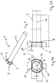
- FIG Fig. 4 Yet another embodiment of an ejector pin (denoted here by 5 ”) is shown in FIG Fig. 4 shown.
- the head 7 has two opposite rectilinear peripheral sections 11, 11 ', one of which is formed by two angularly joined sub-sections 11'. This already ensures a clear definition of the installation position (360-degree symmetry), so that the straight circumferential sections 11, 1 'are followed by circumferential sections 12 that are curved in the same way on both sides.
- the head 7 is produced by upsetting and then working out the straight and curved sections 11, 11 ', 12, 19 and the radii 14 by milling or grinding.
- the opposite rectilinear sections 11, 11 ' are in the embodiments of FIGS. 2 to 4 and 7 to 8b manufactured with a tolerance of approx. 0.02 mm relative to each other. Since the other circumferential sections 12, 19 do not serve to define the angular position of the ejector pin 5, 5 ', 5 ", 5'", these are manufactured with larger tolerances in some embodiments.
- the head 7 is already formed together with the sections 11, 11 ', 12, 19 by upsetting, without subsequent material-removing machining of these sections 11, 11', 12, 19.
- FIG. 11 shows a top view of an exemplary support plate 8 for several ejector pins 5, for example the one in FIG Fig. 2 embodiment shown.
- the support plate 8 has a through-hole 15 with an enlarged diameter compared to the shaft 6 (e.g. enlarged by 0.2 mm) for the purpose of floating accommodation, as well as a recess 16 for the form-fitting accommodation of the head 7 without play within the tolerances ( Note: parallel to the straight circumferential sections 11, larger tolerances - and thus larger Play - present as perpendicular to this, since this parallel direction does not need to be used to define the ejector pin angular position).
- the exemplary support plate 8 has two concentric circular arrangements of such bores 15 and recesses 16, the inner arrangement being designed for smaller ejector pins than the outer arrangement for larger ejector pins.
- the two circumferential head surfaces 11, 11 ' have different lengths A and B, which are caused by the center offset to the central axis.
- the different head circumferential surface lengths A and B also ensure a clear definition of the installation position.
- the circumferential sections 12 additionally have different radii KR1 and KR2, which additionally enables the optical differentiation and recognition of the corresponding installation positions of the ejector pin 5 '".
Abstract
Die Erfindung betrifft Auswerferstifte zum Auswerfen von Formteilen aus Gießwerkzeugen, sowie Tragplatten-Auswerferstift-Anordnungen mit derartigen Auswerferstiften. Die Auswerferstifte umfassen einen Schaft und einen daran angeformten Kopf, wobei der Kopf derart geformt ist, dass der Auswerferstift in einer komplementären Tragplatte nur in einer eindeutigen Einbauposition montierbar ist. Der Kopf weist, in Schaft-Längsrichtung gesehen, wenigstens zwei gegenüberliegende geradlinige Umfangsabschnitte auf, die der Verdrehsicherung dienen, wenn der Auswerferstift in einer komplementären Tragplatte montiert ist. Der Kopf umfasst an seiner Unterseite eine Auflagefläche zur Auflage auf der Tragplatte und weist an seiner Umfangsfläche wenigstens teilweise eine Schräge zur Vorzentrierung auf.The invention relates to ejector pins for ejecting molded parts from casting tools, as well as support plate ejector pin arrangements with such ejector pins. The ejector pins comprise a shaft and a head molded thereon, the head being shaped in such a way that the ejector pin can only be mounted in a complementary support plate in a unique installation position. As seen in the longitudinal direction of the shaft, the head has at least two opposing rectilinear circumferential sections which serve to prevent rotation when the ejector pin is mounted in a complementary support plate. The head comprises a support surface on its underside for resting on the support plate and at least partially has a bevel on its peripheral surface for precentering.
Description
Die vorliegende Erfindung bezieht sich allgemein auf Gießwerkzeuge, und beispielsweise auf einen Auswerferstift zum Auswerfen von Formteilen sowie auf eine Tragplatten-Auswerferstift-Anordnung mit einem oder mehreren solcher Auswerferstifte.The present invention relates generally to casting tools and, for example, to an ejector pin for ejecting molded parts and to a support plate ejector pin assembly having one or more such ejector pins.
In der Spritz- und Druckgusstechnik (z.B. für die Formung von Kunststoffen und niedrigschmelzenden Metalllegierungen) stellt sich allgemein die Aufgabe, am Ende des Gießvorgangs das erstarrte Formteil aus der Gießform herauszunehmen. Hierzu dienen häufig ein oder mehrere Auswerferstifte, welche auf einer beweglichen Tragplatte angeordnet sind und jeweils durch eine Bohrung in die Gießform hineinreichen; üblicherweise schließen die Auswerferstifte bei nicht-betätigtem Auswerfer stirnseitig mit der Innenwandung der Gießform bündig ab.In injection and die casting technology (e.g. for the molding of plastics and low-melting metal alloys), the general task is to remove the solidified molded part from the casting mold at the end of the casting process. One or more ejector pins are often used for this, which are arranged on a movable support plate and each extend through a bore into the casting mold; When the ejector is not operated, the ejector pins usually end flush with the inner wall of the casting mold.
Ein Auswerfen eines gegossenen Teils erfolgt nach Öffnen des Gießwerkzeugs dadurch, dass die Tragplatte mit dem oder den Auswerferstiften in Richtung zur Form bewegt wird, wodurch der oder die Auswerferstifte in die Form eindringen und so das Formteil auswerfen.A cast part is ejected after opening the casting tool in that the support plate with the ejector pin or pins is moved in the direction of the mold, whereby the ejector pin or pins penetrate into the mold and thus eject the molded part.
Ein Beispiel für derartige Auswerferstifte und den beschriebenen Auswerfermechanismus ist aus der
Im Allgemeinen entspricht die stirnseitige Formgebung des Auswerferstiftes der Formgebung des Formwerkzeugs an der Stelle, an welcher der Auswerferstift sitzt. Ist beispielsweise die Wandung des Formwerkzeugs geneigt, so wird der Auswerferstift stirnseitig eine entsprechende Neigung (relativ zu seiner Längsachse) aufweisen. Weist das Formwerkzeug an der entsprechenden Stelle beispielsweise eine Stufe auf, so wird auch der Auswerferstift stirnseitig eine entsprechende Stufe haben. In derartigen Fällen muss der Auswerferstift in einer definierten Position bezüglich Drehung um seine eigene Achse eingebaut sein und gegen Verdrehung um seine eigene Achse gesichert sein.In general, the shape of the end face of the ejector pin corresponds to the shape of the molding tool at the point at which the ejector pin is seated. If, for example, the wall of the molding tool is inclined, the ejector pin will have a corresponding inclination (relative to its longitudinal axis) on the front side. If the molding tool has, for example, a step at the corresponding point, the ejector pin will also have a corresponding step on the face. In such cases, the ejector pin must be installed in a defined position with respect to rotation about its own axis and be secured against rotation about its own axis.
In der
Obgleich mit diesem Vorschlag eine funktionsfähige Verdrehsicherung für Auswerferstifte bereitgestellt wurde, hat sich in der Praxis gezeigt, dass die vorgeschlagene Lösung noch nicht als optimal anzusehen ist. Beispielsweise zeigen die angeformten exzentrischen Köpfe in der Praxis herstellungsbedingt relativ große Toleranzen (im Bereich von 0,2 mm); auch neigen die vorgeschlagenen Auswerferstifte beim Einsetzen in die Tragplatte zum Verspannen.Although this proposal provides a functional anti-rotation device for ejector pins, it has been shown in practice that the proposed solution is not yet to be regarded as optimal. For example, the molded eccentric heads show relatively large tolerances (in the range of 0.2 mm) in practice due to the manufacturing process; the proposed ejector pins also tend to become warped when inserted into the support plate.
Aus
Die Erfindung betrifft einen Auswerferstift zum Auswerfen von Formteilen aus Gießwerkzeugen. Der Auswerferstift umfasst einen Schaft und einen daran angeformten Kopf. Der Kopf ist so geformt ist, dass der Auswerferstift in einer komplementären Tragplatte nur in einer eindeutigen Einbauposition montierbar ist. Der Kopf weist, in Schaft-Längsrichtung gesehen, wenigstens zwei gegenüberliegende geradlinige Umfangsabschitte auf. Diese dienen der Verdrehsicherung, wenn der Auswerferstift in einer komplementären Tragplatte moniert ist. Der Kopf umfasst an seiner Unterseite eine Auflagefläche zur Auflage auf der Tragplatte. Ferner weißt der Kopf an seiner Umfangsfläche, insbesondere an einem unteren Teilabschnitt seiner Umfangsfläche, wenigstens teilweise eine Schräge zur Vorzentrierung auf.The invention relates to an ejector pin for ejecting molded parts from casting tools. The ejector pin comprises a shaft and a head formed thereon. The head is shaped so that the ejector pin can only be mounted in a unique installation position in a complementary support plate. The head has, viewed in the longitudinal direction of the shaft, at least two opposite straight lines Circumferential sections. These are used to prevent rotation when the ejector pin is mounted in a complementary support plate. The head comprises a support surface on its underside for support on the support plate. Furthermore, on its circumferential surface, in particular on a lower section of its circumferential surface, the head at least partially has a bevel for precentering.
Die Schräge kann durch Fräsung oder andere geeignete Herstellungsverfahren ausgebildet sein. Bevorzugt ist sie durch Umformung (z.B. Anstauchung) ausgebildet.The bevel can be formed by milling or other suitable manufacturing processes. It is preferably formed by reshaping (e.g. upsetting).
Die Schräge kann nur an Teilabschnitten an der Umfangsfläche des Kopfes vorgesehen sein. Bevorzugt ist sie jedoch umlaufend um den Kopf ausgebildet.The bevel can only be provided at partial sections on the circumferential surface of the head. However, it is preferably designed to run around the head.
Ferner weist die Schräge den Winkel zur Schaftlängsachse in einem Bereich von 1° bis 25°, bevorzugt 1° bis 20°, insbesondere einen Bereich von 3° bis 10°, besonders bevorzugt in einem Bereich von 4° bis 7° auf.Furthermore, the bevel has the angle to the shaft longitudinal axis in a range from 1 ° to 25 °, preferably 1 ° to 20 °, in particular a range from 3 ° to 10 °, particularly preferably in a range from 4 ° to 7 °.
Die Kopfumfangsfläche umfasst, insbesondere in einem oberen Teilabschnitt der Kopfumfangsfläche, eine Anlagefläche zur Anlage an die komplementäre Ausnehmung in der Tragplatte.The head circumferential surface comprises, in particular in an upper section of the head circumferential surface, a contact surface for contact with the complementary recess in the support plate.
Insbesondere über einen unterschiedlichen Abstand der gegenüberliegenden gradlinigen Umfangsabschnitte zum Schaftmittelpunkt lässt sich ein Mittelversatz generieren. Dieser wiederum hat zur Folge, dass sich unterschiedliche Radien und Flächenlängen ausbilden lassen, die so eine einfache optische Unterscheidung der Einbauposition des Auswerferstiftes ermöglichen.In particular, a mean offset can be generated via a different distance between the opposite straight circumferential sections from the shaft center point. This in turn has the consequence that different radii and surface lengths can be formed, which thus enable a simple visual differentiation of the installation position of the ejector pin.
Beim Einsatz hilft die umlaufende Schräge einer Vorzentrierung des Auswerferstiftes und ermöglicht so eine schnelle und einfache Montage in der jeweiligen Tragplatte, insbesondere in einem Bereich mit einem schrägen Winkel von 1° bis 15°. Zusätzlich ist vorteilhaft eine Montage nur in einer Einbauposition möglich, die insbesondere optisch für einen Nutzer einfach zu erkennen ist.During use, the circumferential incline helps to pre-center the ejector pin and thus enables quick and easy installation in the respective support plate, especially in an area with an inclined angle of 1 ° to 15 °. In addition, assembly is advantageously only possible in one installation position that is easy to see for a user, in particular optically.
Die unterschiedlichen Radien aufgrund des Mittenversatzes verstärken die optische Erkennbarkeit und ermöglichen selbst eine haptische Erkennbarkeit für einen Nutzer. Gleiches gilt für die unterschiedlichen Flächenabstände der Umfangsabschnitte. Der kürzere und der längere Flächenabstand stellen nur eine Einbausituation sicher.The different radii due to the offset increase the visual recognizability and even enable haptic recognizability for a user. The same applies to the different surface distances between the circumferential sections. The shorter and longer surface spacing ensure only one installation situation.
Erfindungsgemäß wird so eine beidseitige Verdrehsicherung bereitgestellt, die eine höhere Genauigkeit gegenüber einer einseitigen Verdrehsicherung aufweist.According to the invention, a double-sided anti-rotation device is thus provided which has a higher degree of accuracy than a one-sided anti-rotation device.
Aufgrund der Anordnung der Verdrehsicherung des Auswerferstiftes und deren Ausbildung an einem unteren Abschnitt der Umfangsfläche des Kopfes sowie der Auflagefläche des Kopfes lässt sich eine schwimmende Lagerung des Auswerferstiftes in der Tragplatte ermöglichen, sodass kein Verspannen des Auswerferstiftes in der Tragplatte auftritt.Due to the arrangement of the anti-rotation device of the ejector pin and its formation on a lower section of the circumferential surface of the head and the bearing surface of the head, a floating mounting of the ejector pin in the support plate can be enabled so that the ejector pin does not become warped in the support plate.
Darüber hinaus ermöglicht die Stauchung des Kopfes auch eine platzsparende Ausbildung der Kopfform, sodass sich enge Abstände zwischen den Auswerferstiften in einer Tragplatte bereitstellen lassen.
Ein weiterer Aspekt betrifft eine Tragplatten-Auswerferstift-Anordnung mit einer Tragplatte mit einer oder mehreren Bohrungen mit Aufnahmen, in die Auswerferstifte der oben genannten Art eingesetzt sind. Die Aufnahmen sind zur Auswerferstift-Kopfform komplementär und nehmen die Köpfe auf. Die Schäfte treten durch die Bohrungen. Die Bohrungen weisen einen um so viel größeren Durchmesser als die Schäfte auf, dass die Position des oder der Auswerferstifte in der Tragplatte in Querrichtung zu den gegenüberliegenden geradlinigen Umfangsabschnitten durch diese Umfangsabschnitte im Zusammenwirken mit dazu komplementären Umfangsabschnitten der Aufnahmen definiert ist, aber nicht durch die Bohrungen.In addition, the compression of the head also enables a space-saving design of the head shape, so that narrow spacings can be provided between the ejector pins in a support plate.
Another aspect relates to a support plate / ejector pin arrangement with a support plate with one or more bores with receptacles into which ejector pins of the above-mentioned type are inserted. The receptacles are complementary to the ejector pin head shape and accommodate the heads. The shafts pass through the holes. The bores have a diameter that is so much larger than the shafts that the position of the ejector pin or pins in the support plate in the transverse direction to the opposing straight circumferential sections is defined by these circumferential sections in cooperation with complementary circumferential sections of the receptacles, but not by the bores .
Weitere Merkmale sind in den offenbarten Vorrichtungen implizit enthalten oder werden für den Fachmann aufgrund der folgenden detaillierten Beschreibung von Ausführungsformen und der angefügten Zeichnung ersichtlich.Further features are implicitly contained in the disclosed devices or will become apparent to a person skilled in the art on the basis of the following detailed description of embodiments and the attached drawings.
Ausführungsformen der Erfindung werden nun beispielhaft und unter Bezugnahme auf die angefügte Zeichnung beschrieben, in der:
-
Fig. 1 eine Seitenansicht einer beispielhaften Spritzgußform in Schnittansicht zeigt, in der Ausführungsformen der erfindungsgemäßen Auswerferstifte eingebaut sind; -
Fig. 2 eine Draufsicht und eine Seitenansicht einer ersten Ausführungsform eines Auswerferstiftes zeigt; -
Fig. 3 eine Draufsicht und eine Seitenansicht einer zweiten Ausführungsform eines Auswerferstiftes zeigt; -
Fig. 4 eine Draufsicht und eine Seitenansicht einer dritten Ausführungsform eines Auswerferstiftes zeigt; -
Fig. 5 eine Draufsicht einer beispielhaften Tragplatte für Auswerferstifte der inFig. 2 dargestellten Ausführungsform zeigt; -
Fig. 6 eine Schnittansicht der Tragplatte vonFig. 5 entlang der Linie A-A zeigt; -
Fig. 7 eine perspektivische Darstellung einer weiteren Ausführungsform eines erfindungsgemäßen Auswerferstiftes zeigt; -
Fig. 8a eine Draufsicht auf die Ausführungsform des Auswerferstiftes ausFig. 7 zeigt; und -
Fig. 8b eine Seitenansicht der Ausführungsform des Auswerferstiftes gemäßFig. 7 zeigt.
-
Fig. 1 shows a side view of an exemplary injection mold in sectional view in which embodiments of the ejector pins according to the invention are installed; -
Fig. 2 Figure 11 shows a top and side view of a first embodiment of an ejector pin; -
Fig. 3 Figure 11 shows a top and side view of a second embodiment of an ejector pin; -
Fig. 4 Figure 9 shows a top and side view of a third embodiment of an ejector pin; -
Fig. 5 a plan view of an exemplary support plate for ejector pins in FIGFig. 2 illustrated embodiment shows; -
Fig. 6 a sectional view of the support plate ofFig. 5 along the line AA; -
Fig. 7 shows a perspective view of a further embodiment of an ejector pin according to the invention; -
Figure 8a a plan view of the embodiment of the ejector pinFig. 7 shows; and -
Figure 8b a side view of the embodiment of the ejector pin according toFig. 7 shows.
Die beschriebenen Ausführungsformen zeigen einen Auswerferstift mit einem Schaft und einem durch Umformung (z.B. Anstauchung) angeformten Kopf. Der Kopf kann auch durch Fräsung oder andere geeignete Verfahren ausgestaltet sein. Der Kopf weist bei den Ausführungsformen - in Schaft-Längsrichtung gesehen - zwei gegenüberliegende geradlinige Umfangsabschnitte auf. Die gegenüberliegenden geradlinigen Umfangsabschnitte dienen der Verdrehsicherung, wenn der Auswerferstift in einer komplementären Tragplatte moniert ist. Die Tragplatte weist hierzu eine komplementäre Ausnehmung zur Aufnahme des Kopfs auf, welche - entsprechend der Kopfform - wenigstens zwei gegenüberliegende geradlinige Umfangsabschnitte aufweist. Bei einigen Ausführungsformen verlaufen die gegenüberliegenden geradlinigen Umfangsabschnitte parallel zueinander. Bei manchen dieser Ausführungsformen sie im gleichen Abstand vom Schaft-Mittelpunkt, sind also symmetrisch zu diesem. Bei anderen dieser Ausführungsformen verlaufen sie hingegen in unterschiedlichem Abstand vom Schaft-Mittelpunkt, sind also unsymmetrisch zu diesem.The described embodiments show an ejector pin with a shaft and a head formed on by deformation (e.g. upsetting). The head can also be designed by milling or other suitable methods. In the embodiments, the head has - viewed in the longitudinal direction of the shaft - two opposing straight circumferential sections. The opposite straight circumferential sections serve to prevent rotation when the ejector pin is mounted in a complementary support plate. For this purpose, the support plate has a complementary recess for receiving the head, which - corresponding to the shape of the head - has at least two opposing rectilinear circumferential sections. In some embodiments, the opposite rectilinear circumferential sections run parallel to one another. In some of these embodiments they are at the same distance from the shaft center point, that is, they are symmetrical to this. In other of these embodiments, however, they run at different distances from the shaft center point, that is, they are asymmetrical to this.
Ein unterschiedlicher Abstand der gegenüberliegenden gradlinigen Umfangsabschnitte zum Schaftmittelpunkt generiert ein Mittelversatz. Dadurch lassen sich unterschiedliche Radien und Flächenlängen ausbilden, die eine einfache optische Unterscheidung der Einbauposition des Auswerferstiftes ermöglichen.A different distance between the opposite straight circumferential sections and the center of the shaft generates a center offset. As a result, different radii and surface lengths can be formed, which enable a simple visual differentiation of the installation position of the ejector pin.
Bei anderen Ausführungsformen verlaufen die gegenüberliegenden geradlinigen Umfangsabschnitte nicht parallel zueinander, sondern zum Beispiel unter einem kleinen Winkel zueinander. Bei manchen Ausführungsformen sind ein oder mehrere der gegenüberliegenden geradlinigen Umfangsabschnitte aus Unterabschnitten winkelig zusammengesetzt sind. Die Eigenschaft "geradlinig" bezieht sich bei diesen also darauf, dass sie aus geradlinigen Unterabschnitten zusammengesetzt sind. Beispielsweise kann der Kopf im Wesentlichen die Form eines Sechskants haben, bei dem jeweils zwei aneinander mit 60 Grad angrenzende Unterabschnitte zusammen einen "geradlinigen, aus Unterabschnitten winkelig zusammengesetzten Umfangsabschnitt" bilden, und sich zwei derartige zusammengesetzte Abschnitte gegenüberliegen (allerdings wird bei einem solchen Sechskant noch eine "symmetrieaufhebende Maßnahme zur Aushebung der 60-Grad-Symmetrie dazukommen, siehe unten).In other embodiments, the opposite straight circumferential sections do not run parallel to one another, but rather, for example, at a small angle to one another. In some embodiments, one or more of the opposing rectilinear circumferential sections are composed of subsections at an angle. The property "straight" refers to the fact that they are composed of straight subsections. For example, the head can essentially have the shape of a hexagon, in which in each case two sub-sections adjoining one another at 60 degrees together form a "rectilinear circumferential section composed of angular sub-sections", and two such combined sections are opposite one another (however, in the case of such a hexagon, a "symmetry-canceling measure to undo the 60-degree symmetry to be added, see below).
Der Kopf ist im Übrigen so geformt, dass der Auswerferstift in der komplementären Tragplatte nur in einer eindeutigen Einbauposition montierbar ist. Anders ausgedrückt bedeutet dies, dass die Kopfform (nur) eine 360-Grad-Symmetrie aufweist, also frühestens nach einer Drehung um 360 Grad mit sich selbst zur Deckung kommt (im Gegensatz dazu hat beispielsweise ein Kopf mit symmetrischen verbundenen und symmetrisch angeordneten geradlinigen Umfangsabschnitten eine 180-Grad-Symmetrie, und ein Sechskantkopf (der nach einer Drehung um 60 Grad in Deckung mit sich selbst kommt) hat eine 60-Grad-Symmetrie).The head is also shaped in such a way that the ejector pin can only be mounted in a clear installation position in the complementary support plate. In other words, this means that the head shape (only) has a 360-degree symmetry, i.e. it comes into congruence with itself at the earliest after a rotation of 360 degrees (in contrast, for example, a head with symmetrically connected and symmetrically arranged straight circumferential sections has a 180 degree symmetry, and a hex head (which comes into register with itself after rotating 60 degrees) has 60 degree symmetry).
Bei Ausführungsformen mit unsymmetrischer Anordnung der gegenüberliegenden geradlinigen Umfangsabschnitte ist diese 360-Grad-Symmetrie bereits durch die Asymmetrie der genannten Umfangsabschnitte gegeben; eine weitere "symmetrieaushebende" Maßnahme bei der Kopfgestaltung ist daher nicht erforderlich (wenn auch nicht ausgeschlossen).In embodiments with an asymmetrical arrangement of the opposing straight circumferential sections, this 360-degree symmetry is already given by the asymmetry of the circumferential sections mentioned; a further "symmetry-relieving" measure in the head design is therefore not necessary (although not excluded).
Bei Ausführungsformen mit symmetrischer Anordnung der gegenüberliegenden geradlinigen Umfangsabschnitte würde ohne weitere "symmetrieaufhebende" Maßnahme z.B. eine 180-Grad-Symmetrie oder z.B. eine 60-Grad-Symmetrie vorliegen (d.h. der Auswerferstift könnte auch um 180 Grad bzw. 60 Grad gedreht in eine Tragplatte eingebaut werden). Bei diesen Ausführungsformen weist daher der Kopf eine Form auf, die einen derartigen, z.B. nur um 180 Grad bzw. 60 Grad gedrehten Einbau ausschließt. Beispielsweise sind bei manchen dieser Ausführungsformen zur Schaffung der eindeutigen Einbauposition ein weiterer geradliniger Umfangsabschnitt, der rechtwinklig zu den gegenüberliegenden geradlinigen Umfangsabschnitten verläuft, sowie ein diesem gegenüberliegenden gekrümmter Umfangsabschnitt vorgesehen. Die Ausgestaltung mit einerseits dem geradlinigen und andererseits dem gekrümmten Umfangsabschnitt hebt die (ansonsten gegebene) 180-Grad-Symmetrie zugunsten einer 360-Grad-Symmetrie auf. Natürlich ist dies nur beispielhaft - gleichermaßen kann jede andere symmetrieaufhebende Formgebung verwendet werden.In the case of embodiments with a symmetrical arrangement of the opposite rectilinear circumferential sections without further "symmetry-canceling" measures, e.g. a 180 degree symmetry or e.g. 60-degree symmetry exist (i.e. the ejector pin could also be installed in a support plate rotated 180 degrees or 60 degrees). In these embodiments, therefore, the head has a shape corresponding to such, e.g. only excludes installation rotated by 180 degrees or 60 degrees. For example, in some of these embodiments, a further rectilinear circumferential section, which runs at right angles to the opposite rectilinear circumferential sections, and a curved circumferential section opposite this, are provided in order to create the unique installation position. The configuration with on the one hand the straight and on the other hand the curved circumferential section removes the (otherwise given) 180-degree symmetry in favor of a 360-degree symmetry. Of course, this is only an example - any other symmetry-canceling shape can equally be used.
Einige der Ausführungsformen sind beispielsweise dadurch hergestellt, dass zunächst der Kopf durch Umformen des Schaftmaterials (z. B. durch Anstauchen) in Rohform herausgebildet wurde, und dann die gegenüberliegenden geradlinigen Umfangsabschnitte durch Materialabtragung, z.B. Fräsen oder Schleifen herausgearbeitet wurden. Die Anstauchung kann dabei zentrisch zur Längsachse des Schafts erfolgen. Bei anderen Ausführungsformen wird der Kopf bereits mit den geradlinigen Unfangsabschnitten durch Uniformen (z.B. Anstauchen) hergestellt, beispielsweise indem das umzuformende Ende des Schafts beim Umformvorgang in einer geeigneten Form angeordnet wird.Some of the embodiments are produced, for example, in that first the Head was formed by reshaping the shaft material (e.g. by upsetting) in raw form, and then the opposite straight circumferential sections were worked out by material removal, e.g. milling or grinding. The upsetting can take place centrally to the longitudinal axis of the shaft. In other embodiments, the head is already produced with the straight peripheral sections by uniforms (eg upsetting), for example by arranging the end of the shaft to be reshaped in a suitable shape during the reshaping process.
Die den geradlinigen Umfangsabschnitten entsprechenden ebenen Flächen können mit deutlich größerer Genauigkeit hergestellt werden als beispielsweise die in der
Die Ausführungsformen beschreiben ferner auch eine Tragplatten-Auswerferstift-Anordnung, also eine Tragplatte mit einem oder mehrerer eingebauten Auswerferstiften der genannten Art. Die Tragplatte weist eine oder mehrere Aufnahmen auf, die zur Auswerferstift-Kopfform komplementär sind, also beispielsweise ebenfalls zwei gegenüberliegende geradlinige Umfangsabschnitte. Die Aufnahmen sind beispielsweise durch Fräsen herstellbar.The embodiments also describe a support plate-ejector pin arrangement, that is, a support plate with one or more built-in ejector pins of the type mentioned. The support plate has one or more receptacles that are complementary to the ejector pin head shape, so for example also two opposing rectilinear peripheral sections. The recordings can be produced, for example, by milling.
Es wurde erkannt, dass die aus der
Hingegen liegen die Verhältnisse bei den Ausführungsformen der Erfindung anders, da hier die beiden gegenüberliegenden geradlinigen Umfangsabschnitte zusammen mit den entsprechenden komplementären Umfangsabschnitten der Ausnehmung alleine - also ohne Abstützung des Schafts an der Schaftbohrung - eine Verdrehsicherung bilden. Vor diesem Hintergrund ist bei einigen Ausführungsformen der Auswerferstift "schwimmend" in der Schaftbohrung gelagert; das heißt, der Durchmesser der Schaftbohrung ist so groß gewählt, dass die Position des Auswerferstiftes in der Tragplatte in Querrichtung zu den gegenüberliegenden geradlinigen Umfangsabschnitten durch diese Umfangsabschnitte im Zusammenwirken mit den dazu komplementären Umfangsabschnitten der Aufnahme definiert ist, aber nicht durch die Schaftbohrung. Beispielsweise hat bei manchen Ausführungsformen die Schaftbohrung einen um 0,1mm größeren Durchmesser als der Schaft, bei anderen Ausführungsformen sogar einen um 0,2mm größeren.In contrast, the situation is different in the embodiments of the invention, since here the two opposite straight circumferential sections together with the corresponding complementary circumferential sections of the recess alone - that is, without supporting the shaft on the shaft bore - form a rotation lock. Against this background, in some embodiments the ejector pin is “floating” in the shaft bore; that is, the diameter of the shaft bore is selected so large that the position of the ejector pin in the support plate in the transverse direction to the opposite straight circumferential sections is defined by these circumferential sections in cooperation with the complementary circumferential sections of the receptacle, but not by the shaft bore. For example, in some embodiments the shaft bore has a diameter 0.1 mm larger than the shaft, in other embodiments it is even 0.2 mm larger.
Mit den Ausführungsformen des Auswerferstiftes lassen sich - wie gesagt - um deutlich verringerte Toleranzen realisieren. Während bei Auswerferstiften mit Exzenterköpfen die Toleranz der Stift-Winkelstellung von einer Reihe (schwierig zu kontrollierender) Faktoren abhängt, wie Kopfdurchmesser, Kopfstellung, Verdickung des Schafts, Einarbeitung der Schaftbohrung in der Tragplatte, Einarbeitung der Kopfform in der Tragplatte), hängt diese Toleranz bei den Ausführungsformen der Erfindung nur von der Toleranz der geradlinigen Umfangsabschnitte relativ zueinander und deren Einarbeitung in der Tragplatte ab. Auch hat sich gezeigt, dass die bei Exzenter-Köpfen beobachtbare Neigung zum Verspannen bei den Ausführungsformen des Auswerferstiftes ausgeschlossen ist. Zudem erlauben die geradlinigen Umfangsabschnitte eine genaue Definierung der Winkelstellung eines Auswerferstiftes, anders als bei den bekannten Exzenterköpfen. Dies erlaubt es, die Stirnseiten der Auswerferstifte außerhalb der Gießform und im noch nicht in die Tragplatte eingebauten Zustand zu bearbeiten, während bei herkömmlichen Auswerferstiften mit Exzenterkopf mangels ausreichend genauer Winkelstellungsdefinition diese Bearbeitung in der Praxis üblicherweise erst bei in die Tragplatte bzw. die Gießform eingebautem Auswerferstift vorgenommen werden konnte.With the embodiments of the ejector pin, as mentioned, significantly reduced tolerances can be achieved. While for ejector pins with eccentric heads, the tolerance of the pin angular position depends on a number of (difficult to control) factors, such as head diameter, head position, thickening of the shaft, incorporation of the shaft bore in the support plate, incorporation of the head shape in the support plate), this tolerance depends the embodiments of the invention depend only on the tolerance of the rectilinear circumferential sections relative to one another and their incorporation in the support plate. It has also been shown that the tendency to tension observed in eccentric heads is excluded in the embodiments of the ejector pin. In addition, the straight circumferential sections allow an exact definition of the angular position of an ejector pin, unlike the known eccentric heads. This allows the end faces of the ejector pins outside of the casting mold and not yet in the support plate in the installed state, whereas with conventional ejector pins with an eccentric head, due to the lack of a sufficiently precise definition of the angular position, this machining could usually only be carried out in practice with the ejector pin installed in the support plate or the casting mold.
Nun zurückkehrend zu
Wie die beispielhafte
Bei diesem Ausführungsbeispiel weist der Kopf 7 zusätzlich eine umlaufende Schräge S auf. Diese Schräge ist auch bei den Ausführungsbeispielen gemäß
Die Schräge S kann einen Winkel zur Längsachse in einem Bereich von 1° bis 25° aufweisen. Bevorzugt liegt dieser Bereich in einem Bereich zwischen 1° bis 15°, besonders bevorzugt liegt der Winkel W bei 5°. Diese dient einer Vorzentrierung für eine einfache und schnelle Montage des Auswerferstiftes 5'" in der Tragplatte.The slope S can have an angle to the longitudinal axis in a range from 1 ° to 25 °. This range is preferably in a range between 1 ° to 15 °, the angle W is particularly preferably 5 °. This is used for pre-centering for a simple and quick installation of the ejector pin 5 '"in the support plate.
Ein weiteres Auführungsbeispiel eines Auswerferstiftes (hier mit 5' bezeichnet) ist in
Ein noch weiteres Auführungsbeispiel eines Auswerferstiftes (hier mit 5" bezeichnet) ist in
Bei manchen der gezeigten Ausführungsformen ist der Kopf 7 durch Anstauchen und anschließendes Herausarbeiten der die geradlinigen und gekrümmten Abschnitte 11, 11', 12, 19 und der Radien 14 durch Fräsen oder Schleifen hergestellt. Die gegenüberliegenden geradlinigen Abschnitte 11, 11' sind bei den Ausführungsformen der
Bei einigen Ausführungsformen ist der Auswerferstift 5, 5', 5", 5'" ein massiver Stift (ohne innere Freimachung). Bei anderen Ausführungsformen ist er hingegen ein Hülsenstift (mit innerer Freimachung), der z.B. in einen feststehenden, in den Formhohlraum 4 ragenden Stift aufnehmen kann (siehe hierzu z.B. die eingangs genannte
Die Form der Ausnehmungen 16 ist komplementär zu derjenigen des Kopfes 7 der Ausführungsform von
Ein weiteres Ausführungsbeispiel eines Auswerferstiftes (hier mit 5"' bezeichnet) ist in
Die Schräge S kann einen Winkel zur Längsachse in einem Bereich von 1° bis 25° aufweisen. Bevorzugt liegt dieser Bereich in einem Bereich zwischen 1° bis 15°, besonders bevorzugt liegt der Winkel W bei 5°. Diese dient einer Vorzentrierung für eine einfache und schnelle Montage des Auswerferstiftes 5'" in der Tragplatte.The slope S can have an angle to the longitudinal axis in a range from 1 ° to 25 °. This range is preferably in a range between 1 ° to 15 °, the angle W is particularly preferably 5 °. This is used for pre-centering for a simple and quick installation of the ejector pin 5 '"in the support plate.
Bei diesem Ausführungsbeispiel hat der Kopf 7 ebenfalls zwei gegenüberliegende geradlinige parallele Umfangsabschnitte 11, die jedoch in unterschiedlichem Abstand zur Längsachse 13 des Auswerferstiftes 5"' zueinander verlaufen. Damit ist bereits für eine eindeutige Definition der Einbauposition (360-Grad-Symmetrie) gesorgt.In this embodiment, the
Zusätzlich weisen die beiden Kopfumfangsflächen 11, 11' unterschiedliche Längen A und B auf, die durch den Mittenversatz zur Mittelachse bedingt sind. Die unterschiedlichen Kopfumfangsflächenlängen A und B sorgen ebenso für eine eindeutige Definition der Einbauposition. Die Umfangsabschnitte 12 weisen zusätzlich unterschiedliche Radien KR1 und KR2 auf, was zusätzlich die optische Unterscheidung und Erkennung der entsprechenden Einbaupositionen des Auswerferstiftes 5'" ermöglicht.In addition, the two circumferential head surfaces 11, 11 'have different lengths A and B, which are caused by the center offset to the central axis. The different head circumferential surface lengths A and B also ensure a clear definition of the installation position. The
Diese Verdrehsicherung des Auswerferstiftes lässt sich schwimmend in einer Tragplatte lagern.This anti-twist device for the ejector pin can be stored floating in a support plate.
Die beschriebenen Ausführungsformen der Erfindung erlauben gegenüber Auswerferstiften des Standes der Technik eine nicht zu Verspannungen führende und wiederholgenaue Auswerferstift-Verdrehsicherung in der Einbauposition in der Tragplatte.In contrast to prior art ejector pins, the described embodiments of the invention permit an ejector pin anti-rotation lock that does not lead to tension and is repeatable in the installation position in the support plate.
Die Winkelstellung eines entsprechend verdrehgesicherten Auswerferstiftes ist genau definiert, so dass eine Bearbeitung der Stimflächenform der Auswerferstifte bereits vor deren Einbau in Trägerplatten und Gießformen erfolgen kann. Die beiden geradlinigen Kopfflächen 11, 11' bilden Bezugsflächen, die zum Ausrichten des Auswerferstiftes genutzt werden können. Die Schräge S ermöglicht eine Vorzentrierung.The angular position of an ejector pin which is secured against rotation is precisely defined, so that the shape of the end face of the ejector pins can be machined before they are installed in carrier plates and casting molds. The two straight head surfaces 11, 11 'form reference surfaces that can be used to align the ejector pin. The slope S enables pre-centering.
Claims (14)
dadurch gekennzeichnet, dass
die Schräge (S) umlaufend um den Kopf (7) ausgebildet ist und/oder einen Winkel zur Schaftlängsachse von 1 bis 20 Grad, insbesondere von 3 bis 10 Grad, aufweist.Ejector pin (5) according to claim 1,
characterized in that
the bevel (S) is formed circumferentially around the head (7) and / or has an angle to the longitudinal axis of the shaft of 1 to 20 degrees, in particular 3 to 10 degrees.
dadurch gekennzeichnet, dass die Kopfumfangsfläche (K), insbesondere an einem oberen Teilabschnitt, eine Anlagefläche (AF) zur Anlage an die komplementäre Ausnehmung in der Tragplatte (8) umfasst.Ejector pin (5) according to claim 1,
characterized in that the head circumferential surface (K), in particular on an upper section, comprises a contact surface (AF) for contact with the complementary recess in the support plate (8).
Applications Claiming Priority (1)
| Application Number | Priority Date | Filing Date | Title |
|---|---|---|---|
| DE202019102059.8U DE202019102059U1 (en) | 2019-04-10 | 2019-04-10 | Auswerfstift with anti-rotation |
Publications (1)
| Publication Number | Publication Date |
|---|---|
| EP3722068A1 true EP3722068A1 (en) | 2020-10-14 |
Family
ID=66816826
Family Applications (1)
| Application Number | Title | Priority Date | Filing Date |
|---|---|---|---|
| EP20169351.2A Pending EP3722068A1 (en) | 2019-04-10 | 2020-04-14 | Ejection pin with anti-rotation feature |
Country Status (2)
| Country | Link |
|---|---|
| EP (1) | EP3722068A1 (en) |
| DE (1) | DE202019102059U1 (en) |
Cited By (1)
| Publication number | Priority date | Publication date | Assignee | Title |
|---|---|---|---|---|
| DE202023103235U1 (en) | 2023-06-13 | 2023-07-11 | Knarr Vertriebs Gmbh | Ejector pin for ejecting molded parts |
Families Citing this family (1)
| Publication number | Priority date | Publication date | Assignee | Title |
|---|---|---|---|---|
| CN112371945B (en) * | 2020-10-20 | 2021-10-08 | 苏州恒荣精密机电有限公司 | Structural member die with high, dense and thin heat dissipation teeth |
Citations (4)
| Publication number | Priority date | Publication date | Assignee | Title |
|---|---|---|---|---|
| DE3345366A1 (en) | 1983-12-15 | 1985-06-27 | Hans-Joachim 4971 Hüllhorst Meyke | Ejector pin for moulds in plastics processing |
| DE4316029C1 (en) | 1993-05-13 | 1994-11-17 | Rainer Knarr | Stepless sleeve ejector |
| DE19607785A1 (en) * | 1996-03-01 | 1997-09-04 | Meyke Hans Joachim | Plastics moulding tool ejector pin for tools |
| DE202004018293U1 (en) | 2004-11-25 | 2005-03-17 | Knarr Rainer | Ejector pin for injection and pressure die casting molding tools has opposing flats on the head to prevent rotation in an ejector plate |
-
2019
- 2019-04-10 DE DE202019102059.8U patent/DE202019102059U1/en active Active
-
2020
- 2020-04-14 EP EP20169351.2A patent/EP3722068A1/en active Pending
Patent Citations (4)
| Publication number | Priority date | Publication date | Assignee | Title |
|---|---|---|---|---|
| DE3345366A1 (en) | 1983-12-15 | 1985-06-27 | Hans-Joachim 4971 Hüllhorst Meyke | Ejector pin for moulds in plastics processing |
| DE4316029C1 (en) | 1993-05-13 | 1994-11-17 | Rainer Knarr | Stepless sleeve ejector |
| DE19607785A1 (en) * | 1996-03-01 | 1997-09-04 | Meyke Hans Joachim | Plastics moulding tool ejector pin for tools |
| DE202004018293U1 (en) | 2004-11-25 | 2005-03-17 | Knarr Rainer | Ejector pin for injection and pressure die casting molding tools has opposing flats on the head to prevent rotation in an ejector plate |
Cited By (1)
| Publication number | Priority date | Publication date | Assignee | Title |
|---|---|---|---|---|
| DE202023103235U1 (en) | 2023-06-13 | 2023-07-11 | Knarr Vertriebs Gmbh | Ejector pin for ejecting molded parts |
Also Published As
| Publication number | Publication date |
|---|---|
| DE202019102059U1 (en) | 2019-05-27 |
Similar Documents
| Publication | Publication Date | Title |
|---|---|---|
| DE3934495C1 (en) | ||
| EP3093080B1 (en) | Die changer with replaceable die and die dome adapted thereto and method for removal and insertion of the replaceable die | |
| EP3468765B1 (en) | Injection mould with adjustable core centering device | |
| EP3722068A1 (en) | Ejection pin with anti-rotation feature | |
| EP3519130A1 (en) | Grooving tool | |
| EP1247596A2 (en) | Guiding device for machine tools | |
| DE102005013563B4 (en) | Ejector system for molding boxes | |
| EP0287777A2 (en) | Clamping device for tools or work pieces having a cylindrical shaft | |
| DE1552646A1 (en) | Broaching tool | |
| EP3595829B1 (en) | Device for shooting a casting core | |
| EP0695619B1 (en) | Injection mould | |
| EP3075504A1 (en) | Device for making concrete moulds in a moulding machine | |
| DE102019104180A1 (en) | One-piece feeder body for use in casting metals | |
| EP2910325A1 (en) | Tool revolver | |
| DE2715301C3 (en) | Device for fixing one object in relation to another, in particular a workpiece carrier | |
| DE102022117325B3 (en) | Slide arrangement | |
| DE10205730A1 (en) | Two-stage ejector on a mold | |
| EP3959058B1 (en) | Injection molding unit for an injection molding machine for processing plastics | |
| DE2639818A1 (en) | SELF-CENTERING AND SELF-CLAMPING CHUCK FOR MACHINE TOOLS, IN PARTICULAR FOR LATHE | |
| DE2550286B2 (en) | Die casting and injection mold | |
| WO2022033883A1 (en) | Powder press for producing pressed articles | |
| DE4233894C2 (en) | Injection molding or pressing tool for processing plastic masses | |
| DE202022104415U1 (en) | slider assembly | |
| EP1590125A1 (en) | Receiving element | |
| DE3105106A1 (en) | Chip-clearing device |
Legal Events
| Date | Code | Title | Description |
|---|---|---|---|
| PUAI | Public reference made under article 153(3) epc to a published international application that has entered the european phase |
Free format text: ORIGINAL CODE: 0009012 |
|
| STAA | Information on the status of an ep patent application or granted ep patent |
Free format text: STATUS: THE APPLICATION HAS BEEN PUBLISHED |
|
| AK | Designated contracting states |
Kind code of ref document: A1 Designated state(s): AL AT BE BG CH CY CZ DE DK EE ES FI FR GB GR HR HU IE IS IT LI LT LU LV MC MK MT NL NO PL PT RO RS SE SI SK SM TR |
|
| AX | Request for extension of the european patent |
Extension state: BA ME |
|
| STAA | Information on the status of an ep patent application or granted ep patent |
Free format text: STATUS: REQUEST FOR EXAMINATION WAS MADE |
|
| 17P | Request for examination filed |
Effective date: 20210414 |
|
| RBV | Designated contracting states (corrected) |
Designated state(s): AL AT BE BG CH CY CZ DE DK EE ES FI FR GB GR HR HU IE IS IT LI LT LU LV MC MK MT NL NO PL PT RO RS SE SI SK SM TR |
|
| STAA | Information on the status of an ep patent application or granted ep patent |
Free format text: STATUS: EXAMINATION IS IN PROGRESS |
|
| TPAC | Observations filed by third parties |
Free format text: ORIGINAL CODE: EPIDOSNTIPA |
|
| 17Q | First examination report despatched |
Effective date: 20210716 |