EP3721735B1 - Tragbare schutzausrüstung - Google Patents
Tragbare schutzausrüstung Download PDFInfo
- Publication number
- EP3721735B1 EP3721735B1 EP20168623.5A EP20168623A EP3721735B1 EP 3721735 B1 EP3721735 B1 EP 3721735B1 EP 20168623 A EP20168623 A EP 20168623A EP 3721735 B1 EP3721735 B1 EP 3721735B1
- Authority
- EP
- European Patent Office
- Prior art keywords
- back protector
- tank element
- protection device
- layer
- personal protection
- Prior art date
- Legal status (The legal status is an assumption and is not a legal conclusion. Google has not performed a legal analysis and makes no representation as to the accuracy of the status listed.)
- Revoked
Links
Images


Classifications
-
- A—HUMAN NECESSITIES
- A41—WEARING APPAREL
- A41D—OUTERWEAR; PROTECTIVE GARMENTS; ACCESSORIES
- A41D13/00—Professional, industrial or sporting protective garments, e.g. surgeons' gowns or garments protecting against blows or punches
- A41D13/05—Professional, industrial or sporting protective garments, e.g. surgeons' gowns or garments protecting against blows or punches protecting only a particular body part
- A41D13/0531—Spine
-
- A—HUMAN NECESSITIES
- A41—WEARING APPAREL
- A41D—OUTERWEAR; PROTECTIVE GARMENTS; ACCESSORIES
- A41D2400/00—Functions or special features of garments
- A41D2400/46—Storage or supply of water for drinking purposes
-
- A—HUMAN NECESSITIES
- A41—WEARING APPAREL
- A41D—OUTERWEAR; PROTECTIVE GARMENTS; ACCESSORIES
- A41D2600/00—Uses of garments specially adapted for specific purposes
- A41D2600/10—Uses of garments specially adapted for specific purposes for sport activities
-
- A—HUMAN NECESSITIES
- A41—WEARING APPAREL
- A41D—OUTERWEAR; PROTECTIVE GARMENTS; ACCESSORIES
- A41D2600/00—Uses of garments specially adapted for specific purposes
- A41D2600/10—Uses of garments specially adapted for specific purposes for sport activities
- A41D2600/104—Cycling
Definitions
- the present disclosure generally refers to a protection device for a protection of a user. More particularly, the present disclosure relates to a wearable protection device to protect a user's body from an impact or fall during the practice of a sport or activity of dynamic type. For example, said device is used to protect a passenger or a driver of a motor vehicle, or a biker, or a skier, or a person during the execution of a work activity exposed to the danger of impacts.
- Wearable protection devices are known, such as for example a back protector for biking use, which comprises one or more substantially rigid or semi-rigid plates, or shields.
- the back protector is worn in close contact with the user's body, in order to protect the back and spine in the event of an impact.
- the present disclosure therefore starts from the position of the technical problem of providing a wearable device for the protection of a user's body from impacts which allows to offer high protection and, at the same time, satisfies further user's needs, and has greater functionality.
- a personal protection device, a clothing article or garment comprising said personal protection device, a method of making said personal protection device, and a use as defined in the respective independent claims are made available. Secondary features of the object of the present disclosure are defined in the corresponding dependent claims.
- the protection device allows meeting one of the user's greatest needs, while performing a sport or dynamic activity, namely that of taking liquids to keep an adequate level of hydration.
- the idea of solution underlying the present disclosure lies in associating a back protector, also called spinal protector, with a tank element, and improving the association and combination of these two elements as much as possible in order to allow their combined use by a user, for example on a clothing article, or garment, or integrated within the clothing article or garment.
- the idea of solution behind the present disclosure consists in providing a personal protection device that guarantees the user's personal protection, against impacts or falls, and the chance to hydrate.
- the back protector acts as a support for the tank element.
- the tank element is therefore firmly coupled and/or connectable with the back protector. That is to say, i.e., that the tank element is associated and/or associable in a firm manner with the back protector.
- the result is a personal protection device that can be individually manipulated and structurally independent and having at least two functions.
- the back protector and the tank element can be manipulated together as if they were a single body, and can be worn with a single action by a user with no need of wearing the tank element and the back protector at different times.
- the personal protection device for the protection of at least one portion of the body of a user comprises a tank element which in use is apt to contain a liquid, and a back protector, coupled with or joined with said tank element, and/or wherein said back protector acts as a support for said tank element.
- the protection device allows to simultaneously guarantee protection and hydration to a user.
- the protection device according to the present invention is therefore configured so that the back protector can act as a support for said tank element.
- the back protector and the tank element can be fixed or coupled in a removable way, that is, permanently or constantly, such that it is necessary to break a link between said two objects in order to separate them.
- the personal protection device can be made as a single piece or "one-piece".
- the back protector of the personal protection device for protection is configured to define a coupling seat apt to allow the coupling of at least one portion of the tank element with the back protector.
- the protector has a designated seat or housing configured to be coupled or associated with said tank element.
- the back protector is configured to form a seat to allow the association or coupling of a portion or region of the tank element with the same back protector.
- the back protector therefore has or is equipped with a seat to which a portion or region of the tank element can be coupled, associated or connected.
- the coupling of at least one portion of the tank element to the back protector is reversible. Therefore, this means that unlike a permanent coupling, where it is necessary to break or violate the integrity of the product to separate the components thereof, the tank element and the back protector can easily be firmly joined with each other or not according to the user's needs.
- the tank element and the back protector can be made as objects that can be individually manipulated. In other words, the back protector and the tank can be separated or decoupled if necessary.
- this entails the possibility of separately using the back protector alone, for example during short-term activities, and of being able to wash and fill the tank element with greater convenience.
- the tank element is rigidly connected or connectable, with a shape coupling, to said back protector to form a single body with said back protector and/or the tank element can be moved together with the back protector and/or it does not hang or swing with respect to the latter.
- the geometry of the tank element and the geometry of the back protector are such as to ensure that the shape coupling of said two objects is rigid. In fact, when these two objects are coupled, the tank element does not hang, swing or dangle, with respect to the back protector. In other words, when coupled, the tank element and the back protector form a single body.
- the tank element cannot move with respect to the back protector, it cannot prevent or hinder a user's movement, for example, by leaning sideways with respect to the back protector or, for example, by tapping or bouncing with respect to the back protector.
- the tank element when coupled with the back protector, can be uniquely movable, that is to say manipulable, jointly with the latter. It follows that, advantageously, the coupling of the back protector and the tank element is a secure coupling, i.e. not slack or loose.
- the tank element forms an appendage on said back protector on one side of said back protector opposite to the user.
- the tank element does not project or protrude from the side of the protection device facing, or in contact with, the user.
- the tank element does not represent an hindrance to the user's movements.
- the tank element also has an aerodynamic shape. In this way, the tank element does not represent an element of aerodynamic resistance and therefore does not hinder the advancement of the user's body during a dynamic activity.
- the back protector includes an outer layer intended to be arranged on an outer side of the personal protection device opposite to the user, and a first base layer or support layer opposite to said outer layer and intended, in use, to face the user and wherein said at least one portion of the tank element is intended to be interposed or contained between the outer layer and the first base layer. That is to say that the back protector is a multi-layered object or element.
- the outer layer of the back protector does not face the user; on the contrary, said first base or support layer, being opposite to the outer layer faces the user.
- the at least one portion of the tank element is intended to be interposed or contained between the outer layer and the first base layer of the back protector. This means that the coupling seat is between said first support, or base, layer and said outer layer.
- the outer layer and the first base, or support, layer of the back protector are firmly joined with each other and the coupling seat comprises a recess surrounded, at least partially, by at least one slot, pocket or slit, made between said two layers. That is to say, that said coupling seat comprises a recess surrounded, at least partially, by a slot, pocket or slit. Consequently, the coupling and decoupling of the back protector and the tank element is facilitated.
- a sort of shape coupling is obtained for the back protector with the tank element.
- Said slot, pocket or slit is configured to receive or house at least part of the tank element.
- the back protector is made of semi-rigid or flexible material while the tank element is made of rigid material.
- the back protector being flexible, or semi-rigid, allows better accompanying the anatomy and movements of the user.
- the tank element being made of rigid material allows limiting the user's unbalance due to the deformation of the tank element due to the displacement of the volume of liquid contained therein following jumps and/or curves.
- the tank element comprises a substantially closed container defining an inner cavity and having a perimetric rim and wherein the portion of the tank element comprises a flap extending along at least part of said perimetric rim and protrudes radially outwards with respect to the inner cavity of the container. That is to say that the portion of the tank element includes a flap or tab projecting outwards with respect to said inner cavity of the container and surrounding the container around the perimeter.
- the portion of the tank element comprises a flap, or tab, which creates a protrusion, outer to said inner cavity, along at least one part of a perimetric rim of the substantially closed container. This simplifies the coupling or housing of the tank element with the back protector. More specifically, said preferred aspect allows facilitating the insertion of the portion inside the slot or pocket of the coupling seat made between the outer layer and the first support, or base, layer of the protector.
- the outer layer of the back protector has or is equipped with an opening at which it can enclose said perimetric rim of the tank element. This means that when the tank element is coupled with the back protector, said perimetric rim of the tank element touches, or is in contact with or matches with, the perimeter of the outer layer at the opening. Furthermore, according to this preferred aspect, an edge, or a portion of an edge, of the outer layer around the opening is not fixed to the first support, or base, layer to form at least one slit between the outer layer and the first support, or base, layer.
- the outer layer along the entire edge around the opening, or in one or more spots around said opening is not made integral with the first base or support layer.
- an edge or a portion of the edge of the outer layer around the opening is free with respect to the first support layer, or base, so as to form said at least one slit between the two layers. It follows, that a slit, slot or pocket is formed where the outer layer and the first base or support layer are not firmly joined or fixed with one another.
- the flap of the tank element allows forming a shape coupling with the slot, pocket or slot between the outer layer and the first base layer, or support layer.
- said flap of the tank element is configured to be inserted inside said slit between the outer layer and the first support layer and/or, vice versa, said slit between the outer layer and the first support, or base, layer is configured to house said flap of the tank element.
- the container of the tank element comprises a concave inner wall, apt to face the first base layer or support layer of the back protector, i.e having an inward curvature with respect to the inner cavity.
- the tank element is made in such a way as to have an ergonomic curvature at the wall facing the first base support layer or support and therefore consequently, in use, towards the user's back.
- the inner wall of the container of the tank element has an inward curvature suitable to accommodate the natural curvature of a user's back.
- the first base layer or support of the flexible protector adjusts to follow the curvature of the tank element and, overall, to create a highly ergonomic protection device.
- the personal protection device comprises one or more belts or straps in order to be directly worn or fixed on a user's body.
- the protection device can be worn by the user, for example, on a jacket or another garment.
- the personal protection device comprises a second base layer or support layer.
- the second base layer or support layer is intended, in use, to face the user and be closer to the user than the first base or support layer.
- the first base, or support, layer is interposed between the second base, or support layer, and the outer layer.
- the presence of the second base layer represents a reinforcement of the structure of the personal protection device and also allows increasing the response, in terms of energy absorption of the protector, in the event of impacts. That is to say that the second base, or support, layer advantageously allows improving the shock absorption capacity of the personal protection device.
- the present disclosure also relates to a clothing article, or garment, such as a suit or jacket, a waistcoat, a vest or similar garment, preferably for dynamic activities such as biking, skiing or the like, comprising the personal protection device according to what has been illustrated so far.
- the article of clothing, or garment can comprise a pocket or other seat where to lodge the personal protection device.
- said pocket or seat is accessible from the outside of the clothing article, or garment, to allow a user to reach, extract or insert said personal protection device.
- the present disclosure also refers to a method of manufacturing a personal protection device as illustrated heretofore.
- the manufacturing method involves:
- the present disclosure also concerns the use of a back protector to support a tank element.
- each embodiment of the object of the present disclosure can have one or more of the advantages listed above; in any case it is not required that each embodiment has all the listed advantages simultaneously.
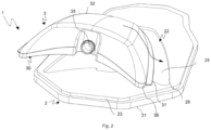
- the reference number 1 indicates an embodiment of a protection device according to the present disclosure as a whole.
- the personal protection device 1 comprises a tank element 3 and a back protector 2, coupled or joined together, preferably in a reversible way.
- the back protector 2 represents or acts as a support for said tank element 3.
- back protector 2 refers within the scope of the present disclosure to a spinal protector.
- Said back protector 2 is apt to be arranged at the user's back, and in particular along his backbone or a portion of it, to protect it from impacts or impacts that can damage it. It follows that in the back protector 2 a long side direction can be identified which, in use, extends in the direction of the user's spine. That is to say that this back protector 2 extends mainly in a main development direction which coincides with said long side direction.
- the back protector 2 is configured to define a coupling seat 22 apt to house therein, preferably in a reversible way, at least one portion of the tank element 3.
- the back protector 2 is therefore configured to form a seat coupling 22 apt to allow the coupling or association or connection of the tank element 3 with the same back protector 2.
- the back protector 2 is apt to receive, or in general to allow the association of, also in a non-permanent way, or according to the user's desire, at least part of the tank element 3. It follows that the back protector 2 and the tank element 3 can be joined together and manipulated together as if they were a single body, or, or if necessary, they can be decoupled from each other and therefore can be individually manipulated. In other words, when coupled together, the back protector 2 and the tank element 3 form a single body or single object, and therefore can only be handled together.
- the tank element 3 can be rigidly connected, with a shape coupling, with said back protector 2. Then, in the personal protection device 1, the tank element 3 is rigidly connected to the back protector 2.
- the tank element forms an appendage on said back protector 2 on one side thereof opposite to the user.
- the tank element 3 forms a protrusion or bulge not facing the user's body, so as not to hinder the movements thereof and make the wearing of the protection device 1 more comfortable. Furthermore, preferably, the tank element 3 has an aerodynamic shape. The tank element 3 has aerodynamic conformation when coupled with the back protector 2. The tank element can be completed with a cannula or straw long enough to reach the mouth of a user when the back protector 2 is worn.
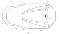
- the back protector 2 includes a first base layer, or support layer, 21 and an outer layer 23.
- the outer layer 23 is intended to be arranged on an outer side of the back protector 2 which is an opposite side to the user.
- the first base layer, or support layer, 21 is opposite with respect to said outer layer 23 and, therefore, is intended to face the user.
- the first base layer or support layer 21 faces the user's back when the back protector 2 is worn.
- the first base layer or support layer 21 faces, in use, towards the user's back.
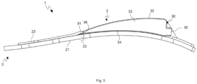
- the first base layer, or support layer 21, and the outer layer 23 form the coupling seat 22 apt to receive or house between them, even in a reversible way, at least one portion of the tank element 3. That is to say that said portion is intended to be interposed, contained, or housed between said two layers, 21 and 23. In other words, this portion is configured to be received between said first base layer 21 and said outer layer 23.
- the first support layer, or base layer, 21 has a greater extension than the outer layer 23 and therefore defines a larger protection surface than the latter.
- the first support layer, or base layer, 21 has thus a greater surface extension than the outer layer 23.
- the first base layer, or support layer, 21 and the outer layer 23 of the back protector 2 are stably coupled, i.e., fixed or joined together.
- the first base layer, or support layer, 21 and the outer layer 23 cannot be separated from each other without breaking a link between said two layers 21, 23 in order to separate them. That is to say that it is necessary to break or violate the integrity of the back protector 2 to separate the layers.
- the first base layer or support 21 and the outer layer 23 are therefore firmly joined with each other.
- the first base layer, or support layer, 21 and the outer layer 23 can be fixed to each other in a way known to the person skilled in the art, such as for example by mechanical fixing means or gluing.
- the outer layer 23 is permanently coupled with the first base layer, or support layer, 21 at almost the entire contact surface between the two layers, 21 and 23.
- said first base or support layer 21 and said outer layer 23 are coupled so as to form among them said coupling seat 22.
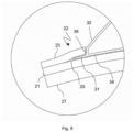
- the coupling seat 22 comprises a recess 24 surrounded, at least partially, by at least one slit 25 arranged or created between the outer layer 23 and the first base layer 21.
- the coupling seat comprises a recess 24 surrounded, at least partially, by a slit 25 made or obtained between the outer layer 23 and the first base layer 21
- the outer layer 23 is shaped so as to present an opening 26.
- said opening 26 of the outer layer 23 is apt to receive the tank element 3.
- the outer layer 23, at the opening 26, is apt to enclose the perimetric rim 36 of the tank element 3.
- the perimetric rim 36 of the tank element 3 is configured to be in contact with the perimetric rim or free rim of the outer layer 23 at the opening 26.
- the perimetric rim of the tank element 3 and the perimetric rim of the outer layer 23 at the opening 26 face to one other.
- the hollow or recess 24 of the coupling seat 22 is thus represented by the space between said opening 26 and the first base or support layer 21.
- the hollow or recess 24 of the coupling seat 22 is, in other words, delimited by or enclosed between the first base or support layer 21 and the perimetric rim or free rim of the outer layer 23 at the opening 26.
- the at least one slit 25 is formed between the two layers, 21 and 23.
- the slit 25 represents a pocket between said two layers 21 and 23.
- the recess 24 is surrounded, at least in part, by at least one slit 25 arranged between the outer layer 23 and the first base layer 21.
- the slit or pocket 25 is created thanks to the fact that the first base layer 21 and the outer layer 23 are not completely joined around said opening 26.
- the slit or pocket 25 is thus made by a free edge of the outer layer 23 around said opening 26 and first base layer 21.
- the tank element 3 is intended in use to contain a liquid.
- the tank element 3 comprises a substantially closed container 30 which defines an inner cavity 33.
- the tank element 3 acts as a water reserve for the user.
- the tank element 3 comprises at least one portion, apt to be coupled, inserted or housed inside the back protector 2.
- said portion comprises a flap 31 which protrudes or project radially outwards with respect to the inner cavity 33 of the substantially closed container 30 of the tank element 3.
- the flap 31 represents a tab which protrudes outwards with respect to the inner cavity 33 of the substantially closed container 30 of the tank element 3 with respect to the inner cavity 33.
- said flap 31 extends outwards along at least part of the perimetric rim 36 of the substantially closed container 30 of the tank element 3.
- the flap or tongue 31 surrounds at least partially along the perimeter the substantially closed container outside the inner cavity 33.
- said flap 31 of the tank element 3 is configured to be inserted within the at least one slit 25 between the outer layer 23 and the first support layer 21.
- the slit 25 between the outer layer 23 and the first support layer 21 is configured to house said flap 31 of the tank element 3.
- the geometry of the flap 31 and the geometry of the slit 25 allow to form a shape coupling with each other.
- the container of the tank element 3 comprises an inner wall 34, apt in use to face the first base layer or support layer 21 of the back protector 2 and one or more outer walls 32.
- the inner wall 34 is joined with the outer wall(s) 32 so as to define said container 30.
- the inner wall 34 and one or more outer walls 32 are coupled together to define said container 30. That is to say that the container comprises at least said inner wall 34 and one or more outer walls 32.
- the tank element 3 further comprises a perimetric rim 36.
- the inner wall 34 is joined with the outer wall(s) 32 along a so-called perimetric rim 36.
- This perimetric rim 36 is therefore the perimetric rim of the container 30.
- the inner wall 34 is concave, i.e. it has an inward curvature with respect to the inner cavity 33. Even more preferably, to ensure maximum comfort, the radius of curvature of the inner wall 34 substantially coincides with the natural radius of curvature of the back of a user.
- the back protector 2 further comprises a third layer 27.
- the back protector 2 can therefore comprise a second base layer or support layer 27 which is intended to face the user and be closer to the user than the first base or support layer 21.
- the first base or support layer 21 is interposed, or interposed or contained between, the second base or support layer 27 and the outer layer 23.
- the back protector 2 is a multilayer element having a sandwich structure.
- the second base layer or support layer 27 is fixed to the first base layer, or support layer, 21.
- the second base layer, or support layer, 27 is only partially fixed to the first base layer or support layer 21.
- the second base layer or support layer 27 is partially fixed to the first base layer, or support layer, 21 only at a central zone or region of said first base layer, or support layer, 21 and said second base layer or support layer 27.
- the back protector 2 is made of semi-rigid or flexible material, such as 100% nitrile rubber, while the tank element 3 is made of rigid material.
- the tank element 3 comprises an opening 35.
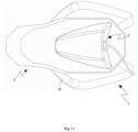
- Said opening 35 allows the insertion of the liquid inside the inner cavity 33 and also allows the insertion inside the same inner cavity 33 of a cannula or straw, as shown in figures 11-12 .
- the opening 35 is surrounded by a threaded wall suitable for coupling with a cap, provided with a counter thread.
- the cap may in turn include a hole that allows the insertion of a small tube or straw inside.
- the personal protection device 1 can comprise one or more belts 42 or straps 41 to be directly worn or fixed on a user's body.
- these belts 42 or straps 41 are coupled with the back protector 2.
- the belts 42 or straps 41 can be of the adjustable type so as to allow a better adaptation to the size of the user's body.
- an article of clothing, or garment comprising the personal protection device 1 as described in detail heretofore, is the subject of the present disclosure.
- this article of clothing, or garment is a suit or jacket, a waistcoat, a vest or similar garment, preferably for dynamic activities such as biking, skiing or the like.
- the article of clothing, or garment can be provided with a pocket, or another seat, to contain, house, insert the personal protection device.
- this pocket or seat is accessible from the outside of the garment, or garment, to allow a user to reach, extract or insert said personal protection device.
- the present disclosure also refers to a method of manufacturing a personal protection device 1 as described heretofore in detail.
- elements and parts of the personal protection device involved in the method and having the same function and the same structure as the elements and parts of the embodiment of structure previously described maintain the same reference number and are not again described in detail.
- the manufacturing method involves the following steps:
- the step of coupling at least one portion of the tank element 3 with the back protector 2 at the coupling seat 22 is performed in a reversible way. That is, the tank element 3 can be decoupled or separated, if necessary, from the back protector 2.
- the outer layer 23 is coupled or permanently fixed with the first base layer, or support layer, 21 at almost the entire contact surface between the two layers, 21 and 23. Only an edge, or a portion of the edge, of the outer layer 23 around the opening 26 is not fixed to the first support, or base, layer 21. In other words, only an edge, or a portion of the edge, of the outer layer 23 around the opening 26 is free with respect to the first support layer, or base, 21. In this way, at least one slit or slot 25 is formed between the two layers, 21 and 23, suitable to receive a portion of the tank element 3, in particular a flap 31.
- the present disclosure also concerns the use of a back protector 2 to support a tank element 3.
Landscapes
- Health & Medical Sciences (AREA)
- Orthopedic Medicine & Surgery (AREA)
- General Health & Medical Sciences (AREA)
- Physical Education & Sports Medicine (AREA)
- Engineering & Computer Science (AREA)
- Textile Engineering (AREA)
- Professional, Industrial, Or Sporting Protective Garments (AREA)
- Electronic Switches (AREA)
- Connector Housings Or Holding Contact Members (AREA)
Claims (20)
- Persönliche Schutzausrüstung (1) zum Schutz von mindestens einem Teilbereich eines Körpers eines Benutzers, wobei die Ausrüstung (1) ein Behälterelement (3), das dazu gedacht ist, in Gebrauch eine Flüssigkeit zu enthalten, und einen Rückenprotektor (2) aufweist, der mit dem Behälterelement (3) verbunden oder zusammengefügt ist, und/oder wobei der Rückenprotektor (2) als Träger für das Behälterelement (3) fungiert,
dadurch gekennzeichnet, dass der Rückenprotektor (2) dafür ausgelegt ist, eine Verbindungsaufnahme (22) zu definieren, die dafür geeignet ist, das Verbinden von mindestens einem Teilbereich des Behälterelements (3) mit dem Rückenprotektor (2) zu ermöglichen. - Persönliche Schutzausrüstung (1) zum Schutz von mindestens einem Teilbereich eines Körpers eines Benutzers, nach Anspruch 1, wobei das Verbinden von mindestens einem Teilbereich des Behälterelements (3) mit dem Rückenprotektor (2) umkehrbar ist.
- Persönliche Schutzausrüstung (1) nach einem der vorhergehenden Ansprüche, wobei das Behälterelement (3) unter Formschluss mit dem Rückenprotektor (2) fest verbunden ist, um einen einzigen Körper mit dem Rückenprotektor zu bilden, und/oder wobei das Behälterelement (3) zusammen mit dem Rückenprotektor bewegbar ist und/oder wobei das Behälterelement (3) in Bezug auf den Rückenprotektor nicht durchhängt oder schwingt.
- Persönliche Schutzausrüstung (1) nach einem der vorhergehenden Ansprüche, wobei das Behälterelement (3) ein Anhangteil am Rückenprotektor (2) auf einer Seite des Rückenprotektors (2) bildet, die dazu gedacht ist, sich in Gebrauch entgegengesetzt zum Benutzer zu befinden.
- Persönliche Schutzausrüstung (1) nach einem der vorhergehenden Ansprüche, wobei der Rückenprotektor (2) eine Außenschicht (23) umfasst, die dazu gedacht ist, in Gebrauch auf einer Außenseite der persönlichen Schutzausrüstung (1) entgegengesetzt zum Benutzer angeordnet zu sein, und eine erste Basisschicht oder Trägerschicht (21) entgegengesetzt zur Außenschicht (3) umfasst, die dazu gedacht ist, in Gebrauch dem Benutzer zugewandt zu sein, und wobei der mindestens eine Teilbereich (31) des Behälterelements (3) dazu gedacht ist, zwischen der Außenschicht (23) und der ersten Basisschicht (21) eingefügt oder enthalten zu sein.
- Persönliche Schutzausrüstung (1) nach Anspruch 5, wobei die erste Basisschicht oder Trägerschicht (21) und die Außenschicht (23) fest aneinander angefügt sind und die Verbindungsaufnahme (22) eine Aussparung (24) aufweist, die zumindest teilweise von mindestens einem Einschubschlitz (25) umgeben ist, der zwischen der Außenschicht (23) und der ersten Basisschicht (21) angeordnet oder hergestellt ist.
- Persönliche Schutzausrüstung (1) nach einem der vorhergehenden Ansprüche, wobei der Rückenprotektor (2) aus einem halbsteifen oder flexiblen Material hergestellt ist und das Behälterelement (3) aus einem starren Material hergestellt ist.
- Persönliche Schutzausrüstung (1) nach einem der vorhergehenden Ansprüche, wobei das Behälterelement (3) ein im Wesentlichen geschlossenes Behältnis aufweist, das einen Innenhohlraum (33) definiert und einen umlaufenden Rand (36) hat, wobei der Teilbereich des Behälterelements (3) eine Zunge (31) aufweist, die sich entlang von mindestens einem Teil des umlaufenden Randes (36) erstreckt und in Bezug auf den Innenhohlraum (33) radial nach außen vorsteht.
- Persönliche Schutzausrüstung (1) nach Anspruch 8, wobei die Außenschicht (23) des Rückenprotektors (2) so geformt ist, dass sie eine Öffnung (26) aufweist, und wobei die Außenschicht (23) an der Öffnung (26) dazu geeignet ist, den umlaufenden Rand (36) des Behältnisses (30) des Behälterelements (3) zu umgeben.
- Persönliche Schutzausrüstung (1) nach Anspruch 9, wobei die Zunge oder ein Zungenteilbereich der Außenschicht (23) um die Öffnung (26) herum nicht an der ersten Träger- oder Basisschicht (21) befestigt ist bzw. in Bezug darauf frei beweglich ist, um den mindestens einen Einschubschlitz (25) zwischen der Außenschicht (23) und der ersten Träger- oder Basisschicht (21) zu bilden.
- Persönliche Schutzausrüstung (1) nach einem der vorhergehenden Ansprüche in Kombination mit Anspruch 8 und Anspruch 6, wobei die Zunge (31) des Behälterelements (3) dafür ausgelegt ist, in den Einschubschlitz (25) zwischen der Außenschicht (23) und der ersten Trägerschicht (21) eingeführt zu werden und/oder der Einschubschlitz (25) zwischen der Außenschicht (23) und der ersten Trägerschicht (21) dafür ausgelegt ist, die Zunge (31) des Behälterelements (3) unterzubringen.
- Persönliche Schutzausrüstung (1) nach einem der vorhergehenden Ansprüche in Kombination mit Anspruch 8, wobei das Behältnis (30) des Behälterelements (3) eine Innenwand (34) aufweist, die dafür geeignet ist, in Gebrauch der ersten Basisschicht oder Trägerschicht (21) des Rückenprotektors (2) zugewandt zu sein, und wobei die Innenwand (34) konkav ist, d.h. eine Einwärtskrümmung in Bezug auf den Innenhohlraum (33) hat.
- Persönliche Schutzausrüstung (1) nach einem der vorhergehenden Ansprüche, wobei das Behälterelement (3) eine aerodynamische Form hat.
- Persönliche Schutzausrüstung (1) nach einem der vorhergehenden Ansprüche, wobei der Rückenprotektor (2) eine zweite Basis- oder Trägerschicht (27) aufweist und die erste Basisschicht oder Trägerschicht (21) zwischen der Außenschicht (23) und der zweiten Basis- oder Trägerschicht (21) eingefügt ist.
- Persönliche Schutzausrüstung (1) nach einem der vorhergehenden Ansprüche, mit einem oder mehreren Gurten (42) oder Riemen (41), die direkt am Körper eines Benutzers zu tragen oder zu fixieren sind.
- Bekleidungsartikel oder Kleidungsstück mit einer persönlichen Schutzausrüstung nach einem der Ansprüche 1 bis 15.
- Bekleidungsartikel oder Kleidungsstück nach Anspruch 16, wobei der Bekleidungsartikel oder das Kleidungsstück für dynamische Aktivitäten wie z.B. Radfahren oder Skifahren gedacht ist.
- Herstellungsverfahren einer persönlichen Schutzausrüstung (1) nach einem der Ansprüche 1 bis 17, die folgenden Schritte umfassend:- Bereitstellen eines Behälterelements (3), das dazu gedacht ist, in Gebrauch eine Flüssigkeit zu enthalten, dadurch gekennzeichnet, dass das Verfahren auch folgende Schritte umfasst:- Bereitstellen eines Rückenprotektors (2) und Definieren einer Verbindungsaufnahme (22) in dem Rückenprotektor (2),- Verbinden von mindestens einem Teilbereich des Behälterelements (3) mit dem Rückenprotektor an der Verbindungsaufnahme (22).
- Herstellungsverfahren einer persönlichen Schutzausrüstung (1) nach Anspruch 18, wobei der Schritt des Verbindens von mindestens einem Teilbereich des Behälterelements (3) mit dem Rückenprotektor (2) an der Verbindungsaufnahme (22) auf umkehrbare Art und Weise erfolgt.
- Herstellungsverfahren einer persönlichen Schutzausrüstung (1) nach Anspruch 18 oder 19, wobei das Bereitstellen eines Rückenprotektors (2) und das Definieren einer Verbindungsaufnahme (22) in dem Rückenprotektor (2) Folgendes vorsieht:- Bereitstellen einer ersten Basisschicht oder Trägerschicht (21), die dazu gedacht ist, dem Benutzer zugewandt zu sein, wenn der Rückenprotektor (2) getragen wird;- Bereitstellen einer entgegengesetzten Außenschicht (23) des Rückenprotektors (2), die eine Öffnung (26) hat und dazu gedacht ist, an einer Außenseite entgegengesetzt zum Benutzer angeordnet zu sein,- Fixieren der ersten Basisschicht oder Trägerschicht (21) und der Außenschicht (23) aneinander, um mindestens einen Einschubschlitz (25) um die Öffnung (26) herum zu bilden, um mindestens den Teilbereich des Behälterelements (3) aufzunehmen oder unterzubringen.
Applications Claiming Priority (1)
| Application Number | Priority Date | Filing Date | Title |
|---|---|---|---|
| IT102019000005718A IT201900005718A1 (it) | 2019-04-12 | 2019-04-12 | Dispositivo indossabile di protezione |
Publications (3)
| Publication Number | Publication Date |
|---|---|
| EP3721735A1 EP3721735A1 (de) | 2020-10-14 |
| EP3721735C0 EP3721735C0 (de) | 2023-08-23 |
| EP3721735B1 true EP3721735B1 (de) | 2023-08-23 |
Family
ID=67384199
Family Applications (1)
| Application Number | Title | Priority Date | Filing Date |
|---|---|---|---|
| EP20168623.5A Revoked EP3721735B1 (de) | 2019-04-12 | 2020-04-08 | Tragbare schutzausrüstung |
Country Status (2)
| Country | Link |
|---|---|
| EP (1) | EP3721735B1 (de) |
| IT (1) | IT201900005718A1 (de) |
Families Citing this family (1)
| Publication number | Priority date | Publication date | Assignee | Title |
|---|---|---|---|---|
| EP4473868A1 (de) * | 2023-06-06 | 2024-12-11 | Evoc Sports GmbH | Oberkörperschutz für radfahrer |
Citations (5)
| Publication number | Priority date | Publication date | Assignee | Title |
|---|---|---|---|---|
| WO2002080715A1 (en) | 2001-04-03 | 2002-10-17 | Spidi Sport S.R.L. | Multifunctional device particularly for motorcyclists |
| US20050034476A1 (en) | 2003-08-16 | 2005-02-17 | Pohr Sebastian Heinz | Portable, personal air conditioning unit attachable to a person |
| WO2007116377A2 (en) | 2006-04-11 | 2007-10-18 | Dainese S.P.A. | Motorcyclist' s suit |
| US7665156B1 (en) | 2005-12-27 | 2010-02-23 | Hewitt Paul B | Hydration and motorcycle protection combination system |
| CN206350518U (zh) | 2016-12-20 | 2017-07-25 | 泉州市三剑户外用品有限公司 | 一种摩托车骑行护背 |
Family Cites Families (2)
| Publication number | Priority date | Publication date | Assignee | Title |
|---|---|---|---|---|
| US7631672B2 (en) * | 2004-11-30 | 2009-12-15 | Christerson Abraham Spencer | Portable hydration system with resupply system |
| CA3013929A1 (en) * | 2016-02-12 | 2017-08-17 | Qore Performance, Inc. | Cooling and hydrating containers and methods of use |
-
2019
- 2019-04-12 IT IT102019000005718A patent/IT201900005718A1/it unknown
-
2020
- 2020-04-08 EP EP20168623.5A patent/EP3721735B1/de not_active Revoked
Patent Citations (5)
| Publication number | Priority date | Publication date | Assignee | Title |
|---|---|---|---|---|
| WO2002080715A1 (en) | 2001-04-03 | 2002-10-17 | Spidi Sport S.R.L. | Multifunctional device particularly for motorcyclists |
| US20050034476A1 (en) | 2003-08-16 | 2005-02-17 | Pohr Sebastian Heinz | Portable, personal air conditioning unit attachable to a person |
| US7665156B1 (en) | 2005-12-27 | 2010-02-23 | Hewitt Paul B | Hydration and motorcycle protection combination system |
| WO2007116377A2 (en) | 2006-04-11 | 2007-10-18 | Dainese S.P.A. | Motorcyclist' s suit |
| CN206350518U (zh) | 2016-12-20 | 2017-07-25 | 泉州市三剑户外用品有限公司 | 一种摩托车骑行护背 |
Non-Patent Citations (1)
| Title |
|---|
| ROCKY MOUNTAIN ATV MC: "Alpinestars Bionic Action Protection Jacket", 30 January 2019 (2019-01-30), XP093190839, Retrieved from the Internet <URL:https://www.youtube.com/watch?v=ZoxvCWxNSEE> |
Also Published As
| Publication number | Publication date |
|---|---|
| EP3721735A1 (de) | 2020-10-14 |
| EP3721735C0 (de) | 2023-08-23 |
| IT201900005718A1 (it) | 2020-10-12 |
Similar Documents
| Publication | Publication Date | Title |
|---|---|---|
| US6615832B1 (en) | Wear article with detachable interface assembly | |
| KR200263746Y1 (ko) | 보강 방탄복 | |
| US3327316A (en) | Wrestler's headgear | |
| US8336124B2 (en) | Upper body protective garment | |
| US5794274A (en) | Chin protector for helmets | |
| US4361970A (en) | Karate foot protector | |
| EP0673610B1 (de) | Schutzhelm für Benutzer einer Zieleinrichtung | |
| HU219439B (hu) | Nadrág csípővédőkkel | |
| US5338315A (en) | Colostomy protection device | |
| US9504308B2 (en) | Fluid reservoir shell | |
| EP3721735B1 (de) | Tragbare schutzausrüstung | |
| KR101297466B1 (ko) | 다단 분리형 보습마스크 | |
| US20080201831A1 (en) | Neck Protective Device | |
| US7975321B1 (en) | Combination neck brace incorporated into a body protector | |
| US20070044210A1 (en) | Integrated fit and retention system | |
| CA3148914A1 (en) | Groin protector with opening hatch | |
| KR102196841B1 (ko) | 의류 | |
| EP0134727A1 (de) | Körperschutzdecke | |
| US20080109948A1 (en) | Storage Pocket For Helmet Cover | |
| CN109744631A (zh) | 防护头盔 | |
| EP3838044B1 (de) | Polsterung für einen schutzhelm | |
| US7900274B2 (en) | Fumble flaps | |
| US10376001B1 (en) | Sports shoulder pads having epaulettes containing slow-response foam inserts | |
| KR200417394Y1 (ko) | 방한용 귀마개 | |
| KR20110038755A (ko) | 시야가림 방지용 모자 |
Legal Events
| Date | Code | Title | Description |
|---|---|---|---|
| PUAI | Public reference made under article 153(3) epc to a published international application that has entered the european phase |
Free format text: ORIGINAL CODE: 0009012 |
|
| STAA | Information on the status of an ep patent application or granted ep patent |
Free format text: STATUS: THE APPLICATION HAS BEEN PUBLISHED |
|
| AK | Designated contracting states |
Kind code of ref document: A1 Designated state(s): AL AT BE BG CH CY CZ DE DK EE ES FI FR GB GR HR HU IE IS IT LI LT LU LV MC MK MT NL NO PL PT RO RS SE SI SK SM TR |
|
| AX | Request for extension of the european patent |
Extension state: BA ME |
|
| STAA | Information on the status of an ep patent application or granted ep patent |
Free format text: STATUS: REQUEST FOR EXAMINATION WAS MADE |
|
| 17P | Request for examination filed |
Effective date: 20210512 |
|
| RBV | Designated contracting states (corrected) |
Designated state(s): AL AT BE BG CH CY CZ DE DK EE ES FI FR GB GR HR HU IE IS IT LI LT LU LV MC MK MT NL NO PL PT RO RS SE SI SK SM TR |
|
| GRAP | Despatch of communication of intention to grant a patent |
Free format text: ORIGINAL CODE: EPIDOSNIGR1 |
|
| STAA | Information on the status of an ep patent application or granted ep patent |
Free format text: STATUS: GRANT OF PATENT IS INTENDED |
|
| INTG | Intention to grant announced |
Effective date: 20230313 |
|
| GRAS | Grant fee paid |
Free format text: ORIGINAL CODE: EPIDOSNIGR3 |
|
| GRAA | (expected) grant |
Free format text: ORIGINAL CODE: 0009210 |
|
| STAA | Information on the status of an ep patent application or granted ep patent |
Free format text: STATUS: THE PATENT HAS BEEN GRANTED |
|
| AK | Designated contracting states |
Kind code of ref document: B1 Designated state(s): AL AT BE BG CH CY CZ DE DK EE ES FI FR GB GR HR HU IE IS IT LI LT LU LV MC MK MT NL NO PL PT RO RS SE SI SK SM TR |
|
| REG | Reference to a national code |
Ref country code: GB Ref legal event code: FG4D |
|
| REG | Reference to a national code |
Ref country code: CH Ref legal event code: EP |
|
| REG | Reference to a national code |
Ref country code: DE Ref legal event code: R096 Ref document number: 602020016045 Country of ref document: DE |
|
| REG | Reference to a national code |
Ref country code: IE Ref legal event code: FG4D |
|
| U01 | Request for unitary effect filed |
Effective date: 20230921 |
|
| U07 | Unitary effect registered |
Designated state(s): AT BE BG DE DK EE FI FR IT LT LU LV MT NL PT SE SI Effective date: 20230927 |
|
| PG25 | Lapsed in a contracting state [announced via postgrant information from national office to epo] |
Ref country code: GR Free format text: LAPSE BECAUSE OF FAILURE TO SUBMIT A TRANSLATION OF THE DESCRIPTION OR TO PAY THE FEE WITHIN THE PRESCRIBED TIME-LIMIT Effective date: 20231124 |
|
| PG25 | Lapsed in a contracting state [announced via postgrant information from national office to epo] |
Ref country code: IS Free format text: LAPSE BECAUSE OF FAILURE TO SUBMIT A TRANSLATION OF THE DESCRIPTION OR TO PAY THE FEE WITHIN THE PRESCRIBED TIME-LIMIT Effective date: 20231223 |
|
| PG25 | Lapsed in a contracting state [announced via postgrant information from national office to epo] |
Ref country code: RS Free format text: LAPSE BECAUSE OF FAILURE TO SUBMIT A TRANSLATION OF THE DESCRIPTION OR TO PAY THE FEE WITHIN THE PRESCRIBED TIME-LIMIT Effective date: 20230823 Ref country code: NO Free format text: LAPSE BECAUSE OF FAILURE TO SUBMIT A TRANSLATION OF THE DESCRIPTION OR TO PAY THE FEE WITHIN THE PRESCRIBED TIME-LIMIT Effective date: 20231123 Ref country code: IS Free format text: LAPSE BECAUSE OF FAILURE TO SUBMIT A TRANSLATION OF THE DESCRIPTION OR TO PAY THE FEE WITHIN THE PRESCRIBED TIME-LIMIT Effective date: 20231223 Ref country code: HR Free format text: LAPSE BECAUSE OF FAILURE TO SUBMIT A TRANSLATION OF THE DESCRIPTION OR TO PAY THE FEE WITHIN THE PRESCRIBED TIME-LIMIT Effective date: 20230823 Ref country code: GR Free format text: LAPSE BECAUSE OF FAILURE TO SUBMIT A TRANSLATION OF THE DESCRIPTION OR TO PAY THE FEE WITHIN THE PRESCRIBED TIME-LIMIT Effective date: 20231124 |
|
| PG25 | Lapsed in a contracting state [announced via postgrant information from national office to epo] |
Ref country code: PL Free format text: LAPSE BECAUSE OF FAILURE TO SUBMIT A TRANSLATION OF THE DESCRIPTION OR TO PAY THE FEE WITHIN THE PRESCRIBED TIME-LIMIT Effective date: 20230823 |
|
| PG25 | Lapsed in a contracting state [announced via postgrant information from national office to epo] |
Ref country code: ES Free format text: LAPSE BECAUSE OF FAILURE TO SUBMIT A TRANSLATION OF THE DESCRIPTION OR TO PAY THE FEE WITHIN THE PRESCRIBED TIME-LIMIT Effective date: 20230823 |
|
| PG25 | Lapsed in a contracting state [announced via postgrant information from national office to epo] |
Ref country code: SM Free format text: LAPSE BECAUSE OF FAILURE TO SUBMIT A TRANSLATION OF THE DESCRIPTION OR TO PAY THE FEE WITHIN THE PRESCRIBED TIME-LIMIT Effective date: 20230823 Ref country code: RO Free format text: LAPSE BECAUSE OF FAILURE TO SUBMIT A TRANSLATION OF THE DESCRIPTION OR TO PAY THE FEE WITHIN THE PRESCRIBED TIME-LIMIT Effective date: 20230823 Ref country code: ES Free format text: LAPSE BECAUSE OF FAILURE TO SUBMIT A TRANSLATION OF THE DESCRIPTION OR TO PAY THE FEE WITHIN THE PRESCRIBED TIME-LIMIT Effective date: 20230823 Ref country code: CZ Free format text: LAPSE BECAUSE OF FAILURE TO SUBMIT A TRANSLATION OF THE DESCRIPTION OR TO PAY THE FEE WITHIN THE PRESCRIBED TIME-LIMIT Effective date: 20230823 Ref country code: SK Free format text: LAPSE BECAUSE OF FAILURE TO SUBMIT A TRANSLATION OF THE DESCRIPTION OR TO PAY THE FEE WITHIN THE PRESCRIBED TIME-LIMIT Effective date: 20230823 |
|
| U20 | Renewal fee for the european patent with unitary effect paid |
Year of fee payment: 5 Effective date: 20240325 |
|
| REG | Reference to a national code |
Ref country code: DE Ref legal event code: R026 Ref document number: 602020016045 Country of ref document: DE |
|
| PLBI | Opposition filed |
Free format text: ORIGINAL CODE: 0009260 |
|
| PLAX | Notice of opposition and request to file observation + time limit sent |
Free format text: ORIGINAL CODE: EPIDOSNOBS2 |
|
| 26 | Opposition filed |
Opponent name: ALPINESTARS SPA Effective date: 20240523 |
|
| PGFP | Annual fee paid to national office [announced via postgrant information from national office to epo] |
Ref country code: GB Payment date: 20240419 Year of fee payment: 5 |
|
| PLBB | Reply of patent proprietor to notice(s) of opposition received |
Free format text: ORIGINAL CODE: EPIDOSNOBS3 |
|
| PG25 | Lapsed in a contracting state [announced via postgrant information from national office to epo] |
Ref country code: MC Free format text: LAPSE BECAUSE OF FAILURE TO SUBMIT A TRANSLATION OF THE DESCRIPTION OR TO PAY THE FEE WITHIN THE PRESCRIBED TIME-LIMIT Effective date: 20230823 |
|
| PG25 | Lapsed in a contracting state [announced via postgrant information from national office to epo] |
Ref country code: MC Free format text: LAPSE BECAUSE OF FAILURE TO SUBMIT A TRANSLATION OF THE DESCRIPTION OR TO PAY THE FEE WITHIN THE PRESCRIBED TIME-LIMIT Effective date: 20230823 |
|
| REG | Reference to a national code |
Ref country code: CH Ref legal event code: PL |
|
| PG25 | Lapsed in a contracting state [announced via postgrant information from national office to epo] |
Ref country code: CH Free format text: LAPSE BECAUSE OF NON-PAYMENT OF DUE FEES Effective date: 20240430 |
|
| PG25 | Lapsed in a contracting state [announced via postgrant information from national office to epo] |
Ref country code: IE Free format text: LAPSE BECAUSE OF NON-PAYMENT OF DUE FEES Effective date: 20240408 |
|
| U20 | Renewal fee for the european patent with unitary effect paid |
Year of fee payment: 6 Effective date: 20250403 |
|
| RDAF | Communication despatched that patent is revoked |
Free format text: ORIGINAL CODE: EPIDOSNREV1 |
|
| PG25 | Lapsed in a contracting state [announced via postgrant information from national office to epo] |
Ref country code: CY Free format text: LAPSE BECAUSE OF FAILURE TO SUBMIT A TRANSLATION OF THE DESCRIPTION OR TO PAY THE FEE WITHIN THE PRESCRIBED TIME-LIMIT; INVALID AB INITIO Effective date: 20200408 |
|
| PG25 | Lapsed in a contracting state [announced via postgrant information from national office to epo] |
Ref country code: HU Free format text: LAPSE BECAUSE OF FAILURE TO SUBMIT A TRANSLATION OF THE DESCRIPTION OR TO PAY THE FEE WITHIN THE PRESCRIBED TIME-LIMIT; INVALID AB INITIO Effective date: 20200408 |
|
| RDAG | Patent revoked |
Free format text: ORIGINAL CODE: 0009271 |
|
| STAA | Information on the status of an ep patent application or granted ep patent |
Free format text: STATUS: PATENT REVOKED |
|
| REG | Reference to a national code |
Ref country code: CH Ref legal event code: N12 Free format text: ST27 STATUS EVENT CODE: U-0-0-N10-N12 (AS PROVIDED BY THE NATIONAL OFFICE) Effective date: 20251015 |
|
| 27W | Patent revoked |
Effective date: 20250520 |
|
| GBPR | Gb: patent revoked under art. 102 of the ep convention designating the uk as contracting state |
Effective date: 20250520 |