EP3721304B1 - Systems, methods, and devices for toolpath virtualization and optimization - Google Patents
Systems, methods, and devices for toolpath virtualization and optimization Download PDFInfo
- Publication number
- EP3721304B1 EP3721304B1 EP18887012.5A EP18887012A EP3721304B1 EP 3721304 B1 EP3721304 B1 EP 3721304B1 EP 18887012 A EP18887012 A EP 18887012A EP 3721304 B1 EP3721304 B1 EP 3721304B1
- Authority
- EP
- European Patent Office
- Prior art keywords
- cutting tool
- toolpath
- tool
- machine
- length
- Prior art date
- Legal status (The legal status is an assumption and is not a legal conclusion. Google has not performed a legal analysis and makes no representation as to the accuracy of the status listed.)
- Active
Links
Images












Classifications
-
- G—PHYSICS
- G05—CONTROLLING; REGULATING
- G05B—CONTROL OR REGULATING SYSTEMS IN GENERAL; FUNCTIONAL ELEMENTS OF SUCH SYSTEMS; MONITORING OR TESTING ARRANGEMENTS FOR SUCH SYSTEMS OR ELEMENTS
- G05B19/00—Program-control systems
- G05B19/02—Program-control systems electric
- G05B19/18—Numerical control [NC], i.e. automatically operating machines, in particular machine tools, e.g. in a manufacturing environment, so as to execute positioning, movement or co-ordinated operations by means of program data in numerical form
- G05B19/416—Numerical control [NC], i.e. automatically operating machines, in particular machine tools, e.g. in a manufacturing environment, so as to execute positioning, movement or co-ordinated operations by means of program data in numerical form characterised by control of velocity, acceleration or deceleration
- G05B19/4163—Adaptive control of feed or cutting velocity
-
- G—PHYSICS
- G05—CONTROLLING; REGULATING
- G05B—CONTROL OR REGULATING SYSTEMS IN GENERAL; FUNCTIONAL ELEMENTS OF SUCH SYSTEMS; MONITORING OR TESTING ARRANGEMENTS FOR SUCH SYSTEMS OR ELEMENTS
- G05B19/00—Program-control systems
- G05B19/02—Program-control systems electric
- G05B19/18—Numerical control [NC], i.e. automatically operating machines, in particular machine tools, e.g. in a manufacturing environment, so as to execute positioning, movement or co-ordinated operations by means of program data in numerical form
- G05B19/4097—Numerical control [NC], i.e. automatically operating machines, in particular machine tools, e.g. in a manufacturing environment, so as to execute positioning, movement or co-ordinated operations by means of program data in numerical form characterised by using design data to control NC machines, e.g. CAD/CAM
-
- G—PHYSICS
- G05—CONTROLLING; REGULATING
- G05B—CONTROL OR REGULATING SYSTEMS IN GENERAL; FUNCTIONAL ELEMENTS OF SUCH SYSTEMS; MONITORING OR TESTING ARRANGEMENTS FOR SUCH SYSTEMS OR ELEMENTS
- G05B2219/00—Program-control systems
- G05B2219/30—Nc systems
- G05B2219/35—Nc in input of data, input till input file format
- G05B2219/35012—Cad cam
-
- G—PHYSICS
- G05—CONTROLLING; REGULATING
- G05B—CONTROL OR REGULATING SYSTEMS IN GENERAL; FUNCTIONAL ELEMENTS OF SUCH SYSTEMS; MONITORING OR TESTING ARRANGEMENTS FOR SUCH SYSTEMS OR ELEMENTS
- G05B2219/00—Program-control systems
- G05B2219/30—Nc systems
- G05B2219/35—Nc in input of data, input till input file format
- G05B2219/35097—Generation of cutter path, offset curve
-
- G—PHYSICS
- G05—CONTROLLING; REGULATING
- G05B—CONTROL OR REGULATING SYSTEMS IN GENERAL; FUNCTIONAL ELEMENTS OF SUCH SYSTEMS; MONITORING OR TESTING ARRANGEMENTS FOR SUCH SYSTEMS OR ELEMENTS
- G05B2219/00—Program-control systems
- G05B2219/30—Nc systems
- G05B2219/49—Nc machine tool, till multiple
- G05B2219/49372—Optimize toolpath pattern for a given cutting layer, mounting sequence
-
- Y—GENERAL TAGGING OF NEW TECHNOLOGICAL DEVELOPMENTS; GENERAL TAGGING OF CROSS-SECTIONAL TECHNOLOGIES SPANNING OVER SEVERAL SECTIONS OF THE IPC; TECHNICAL SUBJECTS COVERED BY FORMER USPC CROSS-REFERENCE ART COLLECTIONS [XRACs] AND DIGESTS
- Y02—TECHNOLOGIES OR APPLICATIONS FOR MITIGATION OR ADAPTATION AGAINST CLIMATE CHANGE
- Y02P—CLIMATE CHANGE MITIGATION TECHNOLOGIES IN THE PRODUCTION OR PROCESSING OF GOODS
- Y02P90/00—Enabling technologies with a potential contribution to greenhouse gas [GHG] emissions mitigation
- Y02P90/02—Total factory control, e.g. smart factories, flexible manufacturing systems [FMS] or integrated manufacturing systems [IMS]
Definitions
- the invention in its several embodiments relates generally to the optimization of machine tool program generation by means of CAM systems and machine tool axes control by means of CNC Controllers using kinematic properties of the tool and the toolpath.
- Computer-aided manufacturing (CAM) systems generate a set of instructions for computer numerical control (CNC) machine tools.
- Such instructions drive cutting tools along complex paths in order to obtain desired model shapes by carving blocks of stock materials.
- Such cutting operations are known as manufacturing cycles, where initially a block of stock material is milled into a target shape to be obtained by the cutting operations of the CNC machine.
- CAD computer-aided design
- toolspaths Utilizing virtualization models allows precise indications regarding the quality of manufacturing and the part finishing before actual cutting operations. Toolpaths may be calculated with greater precision and in a manner which avoids gouging or otherwise damaging the workpiece. Additionally, the user may become aware of the aforementioned problems before the cutting operation where the simulation may have detected such problems at an early phase of the milling process, e.g., before the cutting operation.
- a toolpath is in principle a "tool motion" or a sequence of elementary motions, and therefore it is linked with the machine geometry and the machine physical limits. All machines have areas or directions where the toolpath may be difficult and in certain circumstances a toolpath may not be independently generated from a machine. Many CNC parameters are necessary to be set since changes in speed, velocity, angle, etc. of the milling tool all affect the quality of manufacturing.
- the simulation process is important and useful only if it comes as close to being identical to the CNC system on the machine during the physical cutting phase. Accordingly, determining and displaying such factors in a 3D environment is needed in order to assist the operator with the milling simulation.
- US 2014/156052 A1 discloses a numerical control device including a pulse interpolation unit.
- US 2017/0308057 A1 discloses a computer-implemented method for part analytics of a workpiece machined by at least one CNC machine.
- the invention is defined by a method for determining an optimized toolpath using a computer-aided manufacturing system as defined in claim 1, a device as defined in claim 8, and a computer-aided manufacturing system as defined in claim 9. Further preferred embodiments are defined in the dependent claims.
- the present invention provides a method for determining an optimized toolpath using a computer-aided manufacturing system, wherein the optimized toolpath comprises a toolpath associated with a part of a workpiece and wherein the optimized toolpath is configured for a computer numerical control machine, the method comprising: determining a set of parameters associated with a cutting tool of the computer numerical control machine, the set of parameters comprising pivot, velocity, accelerations, and jerk, wherein the determining is based on kinematic properties of the cutting tool of the computer numerical control machine and a toolpath, wherein velocity, acceleration, and jerk are ratios of a length and have dimensions of length, length 2 , and length 3 , respectively, instead of ratios of a length with dimensions of time, time 2 , or time 3 , respectively, and wherein the kinematic properties of the cutting tool are based on an associated tool end, tool length, and tool axis; determining a cutting tool positioning and a cutting tool movement for performing a machine operation, wherein the determining
- Embodiments may include a computer numerically controlled (CNC) system having: a Computer-Aided Manufacturing (CAM) controller and a CNC controller.
- the CAM controller may be configured to determine, by the CAM processor and memory, at least one of: pivot, velocity, acceleration, and jerk.
- the CNC controller may be configured to control, by the CAM, at least one of: a tool speed, a tool feed, and a tool acceleration based on the determined pivot, velocity, acceleration, and jerk.
- at least one parameter in the CAM controller corresponds to at least one machine parameter of the CNC controller. That is, the CNC controller may be further configured to be optimized in a 5-axis toolpath via determining pivot velocity vectors and further by displaying a real-time visualization of geometry-related kinematic data associated with the toolpath strategy.
- a pivot displacement is the difference between a current pivot and a previous pivot
- a tool end displacement is the difference between a current tool end and a previous tool end
- the velocity is determined based on a ratio of the length of the pivot displacement and the tool end displacement.
- the method may further have a set of optimization rules from at least one of: (1) a set of rules to minimize tool velocity, (2) a set of rules to minimize tool jerk, and (3) a set of rules to minimize tool acceleration.
- the method may further comprise: performing the generated machine operation by the CNC machine, and may be based on a successful determination of the optimized toolpath.
- the present invention provides A device comprising: a processor and addressable memory, the processor configured to: determine a set of parameters associated with a computer numerical control machine, the set of parameters comprising pivot, velocity, accelerations, and jerk, wherein the determining is based on kinematic properties of a cutting tool of the computer numerical control machine and a toolpath, wherein velocity, acceleration, and jerk are ratios of a length and have dimensions of length, length 2 , and length 3 , respectively, instead of ratios of a length with dimensions of time, time 2 , or time 3 , respectively, and wherein the kinematic properties of the cutting tool are based on an associated tool end, tool length, and tool axis; determine a cutting tool positioning and a cutting tool movement for performing a machine operation, wherein the determining of the cutting tool positioning and the cutting tool movement is based on the determined set of parameters associated with the cutting tool of the computer numerical control machine; perform a capability check for the cutting tool positioning and the cutting tool movement based on capabilities
- the present invention provides a computer-aided manufacturing system comprising a virtual machine toolpath optimization component and a positioning movement component, each comprising a processor and an addressable memory; wherein the processor of the positioning movement component is configured to: determine a set of parameters associated with a computer numerical control machine, the set of parameters comprising pivot, velocity, accelerations, and jerk, wherein the determining is based on kinematic properties of a cutting tool of the computer numerical control machine and a toolpath, wherein velocity, acceleration, and jerk are ratios of a length and have dimensions of length, length 2 , and length 3 , respectively, instead of ratios of a length with dimensions of time, time 2 , or time 3 , respectively, and wherein the kinematic properties of the cutting tool are based on an associated tool end, tool length, and tool axis; and determine a cutting tool positioning and a cutting tool movement for performing a machine operation, wherein the determining of the cutting tool positioning and the cutting tool movement is based on the determined set
- the CAM system may further comprise: a toolpath virtualization and optimization system, where the toolpath virtualization and optimization system may be configured to: determine an optimized toolpath in the CAM system, where the optimized toolpath comprises a toolpath associated with a part of a workpiece and where the optimized toolpath may be configured for CNC machine.
- a toolpath virtualization and optimization system may be configured to: determine an optimized toolpath in the CAM system, where the optimized toolpath comprises a toolpath associated with a part of a workpiece and where the optimized toolpath may be configured for CNC machine.
- Computer-aided manufacturing (CAM) computing systems generate, with a high degree of automation, instructions for accurate and efficient cutting operations or machine tasks by using information available from simulated versions of parts, workpieces, and machine tools and its constituents.
- Embodiments of a toolpath virtualization and optimization system and computing devices may facilitate the simulation and visualization of the toolpath, where the toolpath for the milling machine comprises / signifies each tool motion defined by a cutting tool.
- a cycle may be defined as a sequentially ordered set of geometric, logic, and technologic rules that produces a consistent motion of a Cutting Tool (CT) along the workpiece.
- CT Cutting Tool
- the type of motion is used to distinguish one cycle from another. For example, in 3-axis cycles, the CT inclination is constant and the motion of a single point is sufficient to describe the cycle. In 4-axis cycles, the CT inclination may vary with one degree of freedom.
- velocity, acceleration, and jerk may be considered quantities defined as functions of relative positions of specific points of the CT.
- a visualization method may be implemented for toolpath optimization in a 5-axis cycle where pivot, velocity, acceleration, and jerk are a concern.
- a threshold may be determined for scenarios where jerk may exceed a maximum value and, for example, illustrated by a long arrow in the pivot point where such large jerk value has occurred.
- Embodiments of the present application allow for notification of a dangerous point of the toolpath to the user when the order of magnitude of the jerk value is beyond the maximal threshold, where the threshold may be determined based on the specific milling machine and the ability of the milling machine to sustain the motion.
- CAM computing systems comprise a virtual machine toolpath optimization component to generate simulated versions of parts, workpieces, and especially machine tools in the toolpath optimization.
- motions of the cutting tool may be optimized and made reliable, via virtual machine tool models having information, such as a machine's kinematics or a machine's controller specifications to create smooth motions having reduced jerk, where the smooth motions may depend on the user desire and machine capabilities.
- Some embodiments of the virtual machine toolpath optimization component determine cutting tool positioning and movement during cutting and/or non-cutting machine processes on a machine tool which may be characterized by, for example, toolpath virtualization and optimization.
- An example of a CAM system may comprise the virtual machine toolpath optimization component disclosed herein to create positioning motions that are optimal and do not result in undesired contact or velocity with and around the workpiece or machine tool components. Positioning and movement by the cutting tool depend on pivot, velocity, acceleration, and jerk of the cutting tool, where such parameters depend on the tool end, tool length, and tool axis to further optimize the toolpaths. The system and operator of the machine need to take into consideration velocity and acceleration of the cutting tool during operations.
- the virtual machine toolpath optimization component may determine such parameters and the resulting parameters for the toolpath may be communicated to a user or machine operator by the virtual machine toolpath optimization component.
- the virtual machine toolpath optimization component may also transmit such information to a positioning movement computing device to be used in the toolpath optimization process.
- a positioning movement computing device via positioning movement computing devices, a virtual representation of machine tool movement and other components is utilized.
- virtual models of machine tool movements may be used by the CAM system to generate operations which are even more suitable for the desired machine, for example, within machine axis limits, as well as free of collisions or undesired contact with any workpiece or machine components.
- the virtual models may give the tool-motion shape characteristics that make it more compliant with the differential properties of the target surface.
- virtual models may be used to simulate the resulting machining operations to ensure accurate and collision-free results which operate within the machine and cutting tool's capabilities.
- aspects of the present embodiments may determine shape and differential properties of the cutting tool based on a change in concavity of the toolpath. It is presented that changes in concavity of the target surface may cause dangerous points in the cutting and according to the present embodiments, the system may determine and illustrate/show the larger acceleration and larger jerk that result in poor quality of finishing. Since a toolpath is calculated by taking into account all the features of the shape of the target model for the part that must be manufactured, such a shape is usually provided to the CAM software by surface mathematical equations within a CAD file; such equations allow evaluation of the so-called differential properties of the part-surfaces. That is, differential properties rely on the mathematical notion of derivative or differentiation, e.g., the ratio of infinitesimal rates of change. Among those differential properties, the changes in concavity/convexity of the part surfaces may experimentally negatively affect a toolpath, producing large accelerations and/or jerks in specific points of the toolpath.
- the present embodiments of the toolpath virtualization and optimization system provide the CAM system and end-user with a tool for early detection (for example, at simulation phase and before feeding the toolpath to the CNC machine and manufacture for cutting) of such large accelerations and/or jerks. Since large accelerations and/or jerks would typically result in poor finishing quality, the toolpath virtualization and optimization system provide a tool to enable users to modify parameters, e.g., technological or geometrical, involved in toolpath calculation in order to recalculate a new toolpath with smoother characteristics, e.g., smaller jerk/velocity/acceleration.
- Embodiments of the toolpath virtualization and optimization system may be implemented in the CAM and/or at the CNC machine controller providing real-time information of the operations.
- the determining of pivot, velocity, acceleration, and jerk may be by the virtual machine toolpath optimization component and based in part on the cutting tool length of the cutting tool, where every cutting tool has an associated cutting length value. Additionally, the pivot, velocity, acceleration, and jerk may be determined further based on the tool end (TE) and tool axis (TA). All directions/positions/inclinations are intended to be evaluated with respect to a fixed or orthonormal reference frame, which may be jointly liable or in agreement with the target.
- the cutting length of a cutting tool CT may be an absolute value that does not depend on the TE and TA. However, the length of the CT, the TE, and TA may be interrelated in the sense that some inclinations of the CT may lead to more tool engagement than others. That is, the cutting length may be defined as the extension along the cutter of the portion of tool that has cutting ability.
- the virtual machine toolpath optimization component may determine the pivot, velocity, acceleration, and jerk between or within operations which may be: machining operations that may be defined as operations in which a cutting tool is removing material on a specific geometric feature of the part; specific groupings of toolpath elements, which may comprise some portion of a machining operation; and optionally, non-cutting operations.
- the virtualization of the cutting tool movement may comprise a definition of each motion axis on the cutting tool at each of the: tool end, tool axis, and pivot point. The virtualization may also provide the position, velocity, and acceleration limits of each axis, so that the positioning movement computing device may choose the best available axis and speed for the cutting tool at that axis.
- a virtual machine controller may allow the machine tool model to accurately emulate its real-world counterpart based on the received data from the virtual machine toolpath optimization component.
- the virtual machine controller may then provide the machine tool model used by the CAM system.
- the virtualization and optimization are automatically and dynamically determined, displayed for a user, and/or created for the CAM program.
- the virtual machine toolpath optimization component may determine velocity that may be a ratio of the length of a pivot displacement and tool end displacement, where the pivot may be determined based on a tool end and cutting tool length and axial inclination of the cutting tool.
- the tool vector may be normalized using a unit norm vector, i.e., tool axis, where the vector representing the inclination of the tool axis is normalized. Accordingly, a relative velocity of the pivot and the tool end may be in the form of a numeric value and the velocity is a positive value.
- the virtual machine toolpath optimization component may then associate each of the velocity values with a direction in 3D space.
- the direction may be based on a tool end and tool axis set of vectors as noted in the figures.
- the virtual machine toolpath optimization component determines a set of parameters that are dependent on the kinematic properties of the tool and the toolpath used in a milling operation.
- the parameters are visually displayed in a diagram which may be in the same 3D environment in which the result of the milling simulation are reported and depicted in the simulation. That is, the importance of displaying such determined information lies in the fact that these parameters, embodied in vectors orthogonal to the tool trajectory, and having variable length, may provide precise indications about the quality of the manufacturing and the part finishing. Additionally, the determined information may provide indications about the
- the system may use these indicators and recalculate the cycle, especially if there is jerk in the tool motion-where the jerk is larger than a threshold which may cause issues with the cutting-in order to get the jerk to be smaller values that are within set limits.
- FIG. 1 depicts in a functional block diagram, an embodiment of the CAM system 100, where the system may comprise: a virtual machine toolpath optimization component 110, a positioning movement computing device 120 or component, e.g., a link move calculator, and a virtual machine tool simulator 130, each associated with a computer numerical control (CNC) machine tool.
- the positioning movement computing device 120 may receive, from the CAM system, a virtual model 160 of the CNC machine, where the virtual model 160 may comprise a representation of a machine tool and a set of machine tool components, and where the virtual representation of the machine tool may further comprise a set of kinematic constraints associated with the CNC machine tool.
- the virtual machine tool simulator 130 may receive input signals from the virtual model 160.
- each positioning instruction or tool motion may be configured to the specific kinematics of the machine tool, as well as the controller of that machine tool, and optionally, based on the workpiece.
- the virtual model 160 may be modified and in an iterative loop updated based on additional information received from the virtual machine tool simulator 130 and fed back into the positioning movement computing device 120, in effect creating a hysteresis where the state of the system has a dependence on its history.
- the CAM system 100 of FIG. 1 may utilize a virtual machine model 160 that includes: a kinematic definition of the machine and a logical description of the machine tool's controller, whereby the virtual machine tool simulator 130 may transmit or provide input to the virtual machine toolpath optimization component 110.
- An embodiment of a virtual model 160 may comprise solid representations of objects which may be used in the manufacturing process of a part, including, for example, machine tools, fixtures, parts, stocks, tools, and holders.
- the positioning movement computing device 120 may send a virtual machine tool simulation to the virtual machine tool simulator 130 where the virtual machine tool simulation is based on determined parameters by the virtual machine toolpath optimization component 110, the parameters comprising any jerk motion associated with the cutting tool.
- any jerk motion of the cutting tool may be determined and displayed utilizing pivot velocity and pivot acceleration vectors to determine an optimized cutting tool movement 190. That is, each cutting tool movement and machine positioning movement may be computed based on a virtual model of the machine tool and automatically or dynamically optimized by the CAM system. Additionally, via a user display 170, visualization for toolpath optimization is presented to a machine operator or user whereby the machine operator provides user parameters 180 to further optimize the movement of the cutting tool 190. The user may provide the user parameters 180 to the positioning movement computing device 120 or in some embodiments to the virtual machine toolpath optimization component 110.
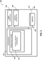
- FIG. 2 illustrates an example top level functional block diagram of a CAM system having a positioning movement computing device embodiment with a virtual machine toolpath optimization component 200.
- the operating environment is shown as a computing device 220 comprising a processor 224, such as a central processing unit (CPU); an addressable memory 227, such as a lookup table, e.g., an array; an external device interface 226, e.g., an optional universal serial bus port and related processing, and/or an Ethernet port and related processing; an output device interface 223; and an optional user interface 229, e.g., an array of status lights, and one or more toggle switches, and/or a display, and/or a keyboard and/or a pointer-mouse system and/or a touch screen.
- a processor 224 such as a central processing unit (CPU); an addressable memory 227, such as a lookup table, e.g., an array; an external device interface 226, e.g., an optional universal serial bus port and
- the addressable memory may, for example, be: flash memory, SSD, EPROM, and/or a disk drive and/or another storage medium. These elements may be in communication with one another via a data bus 228.
- An operating system 225 such as one supporting the execution of applications, may comprise a processor 224 which may be configured to execute steps of a toolpath virtualization and optimization to determine an optimized movement of a cutting tool based on a received virtual model, the virtual model comprising parameters for pivot, velocity, acceleration, and jerk, as determined by the virtual machine toolpath optimization component and based on a set of objects of a machining setup.
- FIGS. 3-25 depict and explain the process in which such parameters are determined and then used to provide a method for toolpath virtualization and optimization in a CAM system.
- determined pivot, velocity, acceleration, and jerk may be checked and verified by a virtual machine toolpath optimization component. This verification ensures that the generated instructions will work on the CNC machine to avoid on-machine verification, which may result in large non-cutting times, or dead times, and may therefore be non-desirable.
- FIG. 3 illustrates a target 320 to be worked on by the CNC machine via manufacturing cycles that is needed to obtain the desired modeled shape.
- the CNC machine may receive instruction from a CAM software which drives the cutting tools along complex paths in order to obtain desired model shapes by carving blocks of stock materials. Such cutting operations are known as manufacturing cycles, and described further below.
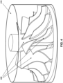
- FIG. 4 illustrates together the stock and a target shape that needs to be obtained via the cutting operations. Further illustrated are an initial stock 410 material and the target 420 shape to be obtained by the aforementioned cutting operations on the CNC machine.
- FIGS. 5A-5B illustrate a cutting tool (CT) 520 and a piece that needs to be cut where the CT 520 should carve the stock 510 but not the target model 515, which is needed to be left behind after the rough material is removed via extracting the final shape from the stock.
- CT cutting tool
- a cycle is determined and designed using and/or based on CAD models where the cycle represents a sequentially ordered set of geometric, logic, and technologic rules that produces a consistent motion of the CT along the piece being worked on.
- This model may be saved, along with the cycle, in a computer digital file, e.g., CAD file.
- the type of motion distinguishes one cycle from another.
- the CT inclination is constant and the motion of a single point is sufficient to describe the cycle.
- the CT inclination may vary with one degree of freedom, and further in 5-axis cycles the CT inclination may virtually assume any direction in 3D space.
- the work piece may also be allotted movement and degrees of freedom where the CT is held steady. That is, in an example of orientable spindle machines, it is the CT being oriented, while in orientable table machines, it is the workpiece that is tilted while the tool remains aligned to a fixed direction in space. Accordingly, a relative inclination between the cutting tool and the workpiece, which may be referred to cutting tool orientation in any way, is considered.
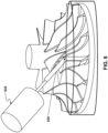
- FIG. 6 illustrates the cutting tool 520 progressively cutting away stock material along the path during various cycles, i.e., toolpaths, where the toolpath may be produced by the CAM software.
- the toolpath is the geometric path through space that the tip 530 of the CT 520 follows in order to produce the desired geometry of the workpiece.
- the tip position may be associated with a directional arrow issued at the point (for each tip position there should be an arrow associated with it).
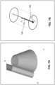
- FIGS. 7A-7B illustrate a cutting tool in a cutter-location (CL) and in the 3 dimensional space having an X, Y, and Z axis (orthonormal reference frame).
- FIG. 7B illustrates an example tool end (TE) 720 (depicted with a filled in black circle) and a tool axis (TA) 730 coming out of the circle in the direction of an arrow (depicted in double solid black lines).
- the CL may be determined based on the TE and TA where in 5-axis a set of geometric attributes may comprise a reference point and a unit norm direction.
- the pair (TE,TA) may be used to define a cutter-location and the ordered sequence of cutter-locations (for example, ranging from 10 0 to 10 6 ) forming a 5-axis toolpath.
- Tool motion may also be represented by kinematic data such as velocity, feedrate, and spindle parameters.
- kinematic data such as velocity, feedrate, and spindle parameters.
- velocity, acceleration, and jerk are used as quantities defined as functions of relative positions of specific points of the CT, for example, as ratios of distances between relative positions.
- FIG. 8 illustrates a 5-axis toolpath with the CT movement producing a number of cutter-locations (CL) 810,820,830,840 and the TE and TA incrementally moving in time and space.
- CL cutter-locations
- other intermediate cutter-locations 840 are depicted as the cutting tool moves from location 820 to location 830.
- the cutting tool is depicted as going from a first CL (or position) 810, to a second CL 820, and finally to an n th CL 830, while having gone through a (finite arbitrary) number of intermediate CLs 840.
- the toolpath produced by the CAM software may be used by the CNC machine at a later phase. That is, based on the complexity of the tool path-defined as an ordered sequence of CL-the value of n in the figure may range from a few units to 10 6 .
- FIG. 9 illustrates the same CLs moving through space but further showing a cutting tool length (CTL) 950 that is associated with each CL and is in addition to showing the CLs 1, 2, ..., n.
- the cutting tool length is a positive value (representing the axial portion of the tool that is able to perform cutting functions) and the TE and TA (a unit norm vector) are shown as before in FIG. 8 , but now with a measured cutting length value (or CTL).
- a pivot may be determined for each CL of the CT which is based on the CTL. So each CTL value is used to adjust the TA and then added to the TE to determine the pivot for each CL, for example: Pivot 1 , Pivot 2 , ..., Pivot n .
- the CT has an associated (positive) cutting tool length CTL value where the CTL is a length measured from the TE along the TA, yielding another characteristic point of the CL, which is referred to as the Pivot.
- FIG. 10 illustrates the cutter locations of the CT and the CTL as a fixed constant value which may be used to determine a velocity of each pivot.
- a velocity scalar value may be based on the module of the difference vector between two adjacent pivots (e.g.,
- the j-th CL (TE j ,TA j ) can also be described as (TE j ,Pivot j ) , or simply (TE j ,P j ) :
- TE j ,P j , P j are 3D points, and we denote the length of the 3D segment from TE j to TE j+1 by
- V j
- as the velocity of Pivot j with respect to the corresponding TE j (j 1,2,...,n-1)
- FIG. 10 further illustrates the cutter locations of the CT and the CTL where the velocity 1010,1020 at each CL is associated with a direction in 3D space.
- This direction may be represented as ⁇ and as a unit norm vector.
- the direction may be determined based on the TE at each subsequent CL and a current CL along with the TA at the current CL.
- a set of pivot velocity vectors may then be determined to represent or provide the characterization of the relative displacement of the pivots with respect to the tool ends.
- the user display of the system may display graphically the numerical values V1 ,V2 ,...,Vn defined previously to associate each of them with a direction in the 3D space.
- the vector Wj Vj * ⁇ j , issued in "Pj” , has a length which is equal to the scalar value Vj : it will be displayed as a visual measure of the relative motion of the pivot point "Pj" with respect to the tool end TEj : the vectors W1 and W2 are shown issued respectively in “P1" , "P2".
- FIG. 11 illustrates the cutter locations of the cutting tool with respect to a target surface area and interaction between tool position and the target, where a target surface 1130 is depicted as being created after the stock is continuously eroded by the cutting tool, by means of the cutting action of the cutting tool.
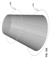
- FIGS. 12A-12B show an example display of the TEs 1210 and pivots 1220 relative to a 5-axis toolpath
- FIG. 12A depicts a collection of tool ends and the associated pivots relative to a 5-axis toolpath.
- FIG. 12B shows the same toolpath with the vectors showing the tool axes vectors 1230. It is noted that the cutting tool is not displayed in these figures.
- FIGS. 13A-13C further illustrate the same workpiece model but now showing a number of pivot velocity vectors 1310 that are then further shown in more detail in FIG. 13B showing a zoomed in version of the circled portion of FIG. 13A .
- FIG. 13C shows a cross-sectional view of the x y axis as to the difference in length between the arrows denoting the pivot velocity vectors.
- the pivot velocity vectors highlight the motion produced by the CT and provide a tool to detect such motions during the toolpath simulation phase (where the user is still able to change parameters of the calculated toolpath in order to avoid such relative motion).
- the difference in length between adjacent arrows may indicate a consistent relative motion of the pivot points with respect to the tool ends. That is, the present systems provide a method for detecting zones of the toolpath where such relative motion occurs, where such motion typically has a negative effect on the kinematics of the rotary axis of the milling machine and may hence impair the final quality of the finished cut model. Accordingly, the pivot velocity vectors of FIGS. 13A-C 1310 may emphasize that kind of motion and provide a method to detect such motion.
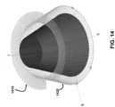
- FIGS. 14 and 15 illustrate the pivot velocity vectors 1410 as determined based on visualization of related kinematic data, where tool axes vectors 1420 are also depicted in FIG. 14 .
- the workpiece is shown in an axonometric view and FIG. 15 shows the same workpiece in an orthogonal view or cross-sectional x y view.
- the axonometric view depicts the tool axes arrows along with difference in length between adjacent pivot velocity vectors.
- An acceleration of the pivot may be determined based on the velocity and TE of the subsequent and current cutting locations. That is, the acceleration for a particular CL of the CT may be based on the determined velocity of the subsequent location and the velocity of the current location (e.g. V j+1 - V j ), along with the TE immediately following the location of the subsequent location of the current TE and the TE at the current location (e.g., TE j+2 - TE j ), as depicted in the example formulas presented below:
- the TE difference may be represented as the modulus of the difference vector.
- a jerk of the pivot may be determined based on the determined acceleration of the subsequent location and the acceleration of the current location (e.g., A j+1 - A j ) and further based on the TE of the current location and the TE immediately following the location of the subsequent location after the current location (e.g., TE j+3 - TE j ).
- the denominators have dimension of length, length 2 , or length 3 instead of time, time 2 , or time 3 , these are not acceleration and jerk in the physical sense.
- the length of the TE's motion is intended to play the role of a time variable. Note also A j and J j might be negative since their numerators can change sign (not their denominators, which are always non-negative).
- a direction in 3D space may be associated with A j and J j by defining the vectors:
- FIGS. 16A-16B show the velocity vectors, acceleration vectors, and jerk vectors at each CL, 1, 2, 3, ..., n.
- the Jerk may be omitted from display as the velocity and acceleration vectors are used by the toolpath virtualization and optimization system. That is, the toolpath virtualization and optimization system may use such data before or during (e.g., in real-time) the CNC phase where the machine receives the data and begins the physical cutting / machining of the workpiece.
- the present embodiments address the functionality of the toolpath virtualization and optimization system. Some aspects of the examples provided are related to how the virtualization model may be affected based on the numerical values of each of the velocity, acceleration, and jerk vectors. For example:
- can happen: in such case the zero value of
- FIGS. 17, 18 , and 19A-D illustrate some examples of visually displayed pivot velocities, accelerations, and jerks in various combinations for a real CAD_CAM model.
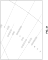
- FIGS. 20-25 further illustrate the jerk visualization determined by the toolpath virtualization and optimization system.
Landscapes
- Engineering & Computer Science (AREA)
- Human Computer Interaction (AREA)
- Manufacturing & Machinery (AREA)
- Physics & Mathematics (AREA)
- General Physics & Mathematics (AREA)
- Automation & Control Theory (AREA)
- Numerical Control (AREA)
Applications Claiming Priority (2)
| Application Number | Priority Date | Filing Date | Title |
|---|---|---|---|
| US201762595505P | 2017-12-06 | 2017-12-06 | |
| PCT/US2018/064330 WO2019113370A1 (en) | 2017-12-06 | 2018-12-06 | Systems, methods, and devices for toolpath virtualization and optimization |
Publications (3)
| Publication Number | Publication Date |
|---|---|
| EP3721304A1 EP3721304A1 (en) | 2020-10-14 |
| EP3721304A4 EP3721304A4 (en) | 2021-08-25 |
| EP3721304B1 true EP3721304B1 (en) | 2024-07-24 |
Family
ID=66658012
Family Applications (1)
| Application Number | Title | Priority Date | Filing Date |
|---|---|---|---|
| EP18887012.5A Active EP3721304B1 (en) | 2017-12-06 | 2018-12-06 | Systems, methods, and devices for toolpath virtualization and optimization |
Country Status (5)
| Country | Link |
|---|---|
| US (1) | US10877463B2 (https=) |
| EP (1) | EP3721304B1 (https=) |
| JP (1) | JP7011064B2 (https=) |
| CN (1) | CN111819504B (https=) |
| WO (1) | WO2019113370A1 (https=) |
Families Citing this family (6)
| Publication number | Priority date | Publication date | Assignee | Title |
|---|---|---|---|---|
| JP7087316B2 (ja) * | 2017-09-27 | 2022-06-21 | オムロン株式会社 | 情報処理装置、情報処理方法およびプログラム |
| CN114245884B (zh) * | 2019-07-26 | 2024-10-29 | 赫克斯冈技术中心 | 用于计算机数控加工刀具的优化 |
| EP4163740B1 (en) * | 2021-10-11 | 2024-04-24 | Hexagon Technology Center GmbH | Digital twin |
| JP7157886B1 (ja) | 2022-02-14 | 2022-10-20 | Dmg森精機株式会社 | 情報処理装置、工作機械および情報処理プログラム |
| EP4332701A1 (de) * | 2022-08-30 | 2024-03-06 | Siemens Aktiengesellschaft | Systeme und verfahren zur unterstützung eines bearbeitungsprozesses |
| CN116700149A (zh) * | 2023-07-05 | 2023-09-05 | 沈阳中科数控技术股份有限公司 | 一种数控加工刀具路径的自适应滤波优化方法 |
Family Cites Families (19)
| Publication number | Priority date | Publication date | Assignee | Title |
|---|---|---|---|---|
| US6782306B2 (en) * | 1999-12-16 | 2004-08-24 | Siemens Energy & Automation | Motion control system and method utilizing spline interpolation |
| US7792604B2 (en) * | 2005-03-23 | 2010-09-07 | Hurco Companies, Inc. | Method of performing additive lookahead for adaptive cutting feedrate control |
| DE102005061570A1 (de) * | 2005-12-22 | 2007-07-05 | Siemens Ag | Ermittlungsverfahren für eine lagegeführte abzufahrende Grobbahn |
| EP1839806B1 (en) * | 2006-03-27 | 2009-04-29 | Fanuc Ltd | Automatic tool changing method and device for machine tool controlled by numerical controller |
| JP4796936B2 (ja) * | 2006-11-01 | 2011-10-19 | 株式会社ソディック | 加工制御装置 |
| CN101493686B (zh) * | 2009-02-26 | 2010-07-28 | 上海交通大学 | 刀具模态参数不确定的曲面五轴数控工艺参数优化方法 |
| CN101859126B (zh) * | 2010-04-30 | 2011-11-16 | 西北工业大学 | 五坐标数控加工刀具路径转换方法 |
| US8423172B2 (en) * | 2010-05-21 | 2013-04-16 | Flow International Corporation | Automated determination of jet orientation parameters in three-dimensional fluid jet cutting |
| CN102331749B (zh) * | 2010-07-15 | 2013-06-05 | 沈阳黎明航空发动机(集团)有限责任公司 | 一种数控加工工艺参数优化方法 |
| JP5417390B2 (ja) * | 2011-07-29 | 2014-02-12 | 新日本工機株式会社 | 数値制御装置 |
| CN102411334B (zh) * | 2011-10-10 | 2013-11-20 | 上海交通大学 | 插铣刀具路径优化方法 |
| GB201204908D0 (en) * | 2012-03-21 | 2012-05-02 | Delcam Plc | Method and system for testing a machine tool |
| EP2862030B1 (en) * | 2012-06-19 | 2022-04-27 | Hexagon Technology Center GmbH | Computer aided manufacturing (cam) integrated computer numerically controlled (cnc) control of machines |
| US9104192B2 (en) * | 2012-06-27 | 2015-08-11 | Mitsubishi Electric Research Laboratories, Inc. | System and method for controlling machines according to pattern of contours |
| US9164503B2 (en) * | 2012-07-13 | 2015-10-20 | The Boeing Company | Method of optimizing toolpaths using medial axis transformation |
| WO2016065491A1 (en) * | 2014-10-31 | 2016-05-06 | Cloudbased Industry 4.0 Technologies Ag | Method for optimizing the productivity of a machining process of a cnc machine |
| CN107111297B (zh) * | 2014-10-31 | 2021-03-26 | 制造业大数据有限公司 | 用于由至少一台计算机数控机器加工的工件的部件分析的计算机实现方法 |
| CN104615084B (zh) * | 2015-01-23 | 2017-04-12 | 大连理工大学 | 加工进给速度优化的刀轨曲线轮廓误差补偿方法 |
| JP6490125B2 (ja) * | 2017-03-10 | 2019-03-27 | ファナック株式会社 | 数値制御装置及びcad/cam−cnc統合システム |
-
2018
- 2018-12-06 WO PCT/US2018/064330 patent/WO2019113370A1/en not_active Ceased
- 2018-12-06 US US16/212,466 patent/US10877463B2/en active Active
- 2018-12-06 EP EP18887012.5A patent/EP3721304B1/en active Active
- 2018-12-06 CN CN201880079049.7A patent/CN111819504B/zh active Active
- 2018-12-06 JP JP2020528331A patent/JP7011064B2/ja active Active
Also Published As
| Publication number | Publication date |
|---|---|
| EP3721304A4 (en) | 2021-08-25 |
| EP3721304A1 (en) | 2020-10-14 |
| US20190171189A1 (en) | 2019-06-06 |
| CN111819504A (zh) | 2020-10-23 |
| JP2021505990A (ja) | 2021-02-18 |
| US10877463B2 (en) | 2020-12-29 |
| WO2019113370A8 (en) | 2020-07-02 |
| WO2019113370A1 (en) | 2019-06-13 |
| JP7011064B2 (ja) | 2022-01-26 |
| CN111819504B (zh) | 2023-10-10 |
Similar Documents
| Publication | Publication Date | Title |
|---|---|---|
| EP3721304B1 (en) | Systems, methods, and devices for toolpath virtualization and optimization | |
| JP7015041B2 (ja) | 切削シミュレーション方法および装置 | |
| US10987774B2 (en) | High performance multi-axis milling | |
| US11656600B2 (en) | Simulation apparatus | |
| CN111324977B (zh) | 利用动态位置误差模拟切削方法 | |
| US12017364B2 (en) | Motion planning graph generation user interface, systems, methods and articles | |
| She et al. | Postprocessor development of a five-axis machine tool with nutating head and table configuration | |
| WO2015041027A1 (en) | Simulation system and method for determining feedrates of tool | |
| Pollák et al. | Utilization of generative design tools in designing components necessary for 3D printing done by a robot | |
| US20030204284A1 (en) | Method for virtual inspection of virtually machined parts | |
| Rivière-Lorphèvre et al. | Cutting force prediction in robotic machining | |
| US20220342381A1 (en) | Managing a machine tool method, for example method of mapping toolpath data and machine code, a control device, and a machine tool | |
| Duvedi et al. | The edge–torus tangency problem in multipoint machining of triangulated surface models | |
| CN104570946B (zh) | 基于可视锥理论的数控加工刀具‑工件间无碰撞加工方法 | |
| Zhang et al. | Design and development of an in situ machining simulation system using augmented reality technology | |
| Estrems et al. | Trajectory generation in 5-axis milling of freeform surfaces using circular arc approximation and its influence in surface roughness | |
| Zekalmi et al. | New fast micro-topography estimation algortihms for 5 axis milling | |
| WO2022264338A1 (ja) | 制御装置、干渉チェック装置、及び制御システム | |
| Erdim et al. | High accuracy computation of geometric properties of cutter workpiece intersection using distance fields for NC milling | |
| Watanabe et al. | Development of tool collision avoidance method adapted to uncut workpiece shape | |
| Taner et al. | Integrated simulation system for 5-axis milling cycles | |
| CN121209417B (zh) | 刀具路径避让点规划方法、装置、设备、介质及产品 | |
| He et al. | A haptic virtual turning operation system | |
| Bilalis et al. | Model for surface-roughness parameters determination in a virtual machine shop environment | |
| Hamiche et al. | Modeling of cutting forces in five-axis milling of sculptured surfaces directly from a CAM tool path |
Legal Events
| Date | Code | Title | Description |
|---|---|---|---|
| STAA | Information on the status of an ep patent application or granted ep patent |
Free format text: STATUS: THE INTERNATIONAL PUBLICATION HAS BEEN MADE |
|
| PUAI | Public reference made under article 153(3) epc to a published international application that has entered the european phase |
Free format text: ORIGINAL CODE: 0009012 |
|
| STAA | Information on the status of an ep patent application or granted ep patent |
Free format text: STATUS: REQUEST FOR EXAMINATION WAS MADE |
|
| 17P | Request for examination filed |
Effective date: 20200527 |
|
| AK | Designated contracting states |
Kind code of ref document: A1 Designated state(s): AL AT BE BG CH CY CZ DE DK EE ES FI FR GB GR HR HU IE IS IT LI LT LU LV MC MK MT NL NO PL PT RO RS SE SI SK SM TR |
|
| AX | Request for extension of the european patent |
Extension state: BA ME |
|
| DAV | Request for validation of the european patent (deleted) | ||
| DAX | Request for extension of the european patent (deleted) | ||
| A4 | Supplementary search report drawn up and despatched |
Effective date: 20210727 |
|
| RIC1 | Information provided on ipc code assigned before grant |
Ipc: G05B 19/402 20060101AFI20210721BHEP Ipc: G05B 19/404 20060101ALI20210721BHEP Ipc: G05B 19/406 20060101ALI20210721BHEP Ipc: G05B 19/4061 20060101ALI20210721BHEP Ipc: G05B 19/4093 20060101ALI20210721BHEP Ipc: G05B 19/4097 20060101ALI20210721BHEP Ipc: G05B 19/414 20060101ALI20210721BHEP Ipc: G05B 19/416 20060101ALI20210721BHEP |
|
| RAP1 | Party data changed (applicant data changed or rights of an application transferred) |
Owner name: HEXAGON TECHNOLOGY CENTER GMBH |
|
| STAA | Information on the status of an ep patent application or granted ep patent |
Free format text: STATUS: EXAMINATION IS IN PROGRESS |
|
| 17Q | First examination report despatched |
Effective date: 20230313 |
|
| GRAP | Despatch of communication of intention to grant a patent |
Free format text: ORIGINAL CODE: EPIDOSNIGR1 |
|
| STAA | Information on the status of an ep patent application or granted ep patent |
Free format text: STATUS: GRANT OF PATENT IS INTENDED |
|
| INTG | Intention to grant announced |
Effective date: 20240306 |
|
| GRAS | Grant fee paid |
Free format text: ORIGINAL CODE: EPIDOSNIGR3 |
|
| GRAA | (expected) grant |
Free format text: ORIGINAL CODE: 0009210 |
|
| STAA | Information on the status of an ep patent application or granted ep patent |
Free format text: STATUS: THE PATENT HAS BEEN GRANTED |
|
| AK | Designated contracting states |
Kind code of ref document: B1 Designated state(s): AL AT BE BG CH CY CZ DE DK EE ES FI FR GB GR HR HU IE IS IT LI LT LU LV MC MK MT NL NO PL PT RO RS SE SI SK SM TR |
|
| REG | Reference to a national code |
Ref country code: GB Ref legal event code: FG4D |
|
| REG | Reference to a national code |
Ref country code: CH Ref legal event code: EP |
|
| REG | Reference to a national code |
Ref country code: DE Ref legal event code: R096 Ref document number: 602018072309 Country of ref document: DE |
|
| REG | Reference to a national code |
Ref country code: IE Ref legal event code: FG4D |
|
| REG | Reference to a national code |
Ref country code: LT Ref legal event code: MG9D |
|
| REG | Reference to a national code |
Ref country code: NL Ref legal event code: MP Effective date: 20240724 |
|
| PG25 | Lapsed in a contracting state [announced via postgrant information from national office to epo] |
Ref country code: PT Free format text: LAPSE BECAUSE OF FAILURE TO SUBMIT A TRANSLATION OF THE DESCRIPTION OR TO PAY THE FEE WITHIN THE PRESCRIBED TIME-LIMIT Effective date: 20241125 |
|
| REG | Reference to a national code |
Ref country code: AT Ref legal event code: MK05 Ref document number: 1706876 Country of ref document: AT Kind code of ref document: T Effective date: 20240724 |
|
| PG25 | Lapsed in a contracting state [announced via postgrant information from national office to epo] |
Ref country code: NL Free format text: LAPSE BECAUSE OF FAILURE TO SUBMIT A TRANSLATION OF THE DESCRIPTION OR TO PAY THE FEE WITHIN THE PRESCRIBED TIME-LIMIT Effective date: 20240724 |
|
| PG25 | Lapsed in a contracting state [announced via postgrant information from national office to epo] |
Ref country code: PT Free format text: LAPSE BECAUSE OF FAILURE TO SUBMIT A TRANSLATION OF THE DESCRIPTION OR TO PAY THE FEE WITHIN THE PRESCRIBED TIME-LIMIT Effective date: 20241125 Ref country code: NL Free format text: LAPSE BECAUSE OF FAILURE TO SUBMIT A TRANSLATION OF THE DESCRIPTION OR TO PAY THE FEE WITHIN THE PRESCRIBED TIME-LIMIT Effective date: 20240724 |
|
| PG25 | Lapsed in a contracting state [announced via postgrant information from national office to epo] |
Ref country code: NO Free format text: LAPSE BECAUSE OF FAILURE TO SUBMIT A TRANSLATION OF THE DESCRIPTION OR TO PAY THE FEE WITHIN THE PRESCRIBED TIME-LIMIT Effective date: 20241024 |
|
| PG25 | Lapsed in a contracting state [announced via postgrant information from national office to epo] |
Ref country code: PL Free format text: LAPSE BECAUSE OF FAILURE TO SUBMIT A TRANSLATION OF THE DESCRIPTION OR TO PAY THE FEE WITHIN THE PRESCRIBED TIME-LIMIT Effective date: 20240724 Ref country code: GR Free format text: LAPSE BECAUSE OF FAILURE TO SUBMIT A TRANSLATION OF THE DESCRIPTION OR TO PAY THE FEE WITHIN THE PRESCRIBED TIME-LIMIT Effective date: 20241025 Ref country code: FI Free format text: LAPSE BECAUSE OF FAILURE TO SUBMIT A TRANSLATION OF THE DESCRIPTION OR TO PAY THE FEE WITHIN THE PRESCRIBED TIME-LIMIT Effective date: 20240724 |
|
| PG25 | Lapsed in a contracting state [announced via postgrant information from national office to epo] |
Ref country code: BG Free format text: LAPSE BECAUSE OF FAILURE TO SUBMIT A TRANSLATION OF THE DESCRIPTION OR TO PAY THE FEE WITHIN THE PRESCRIBED TIME-LIMIT Effective date: 20240724 |
|
| PG25 | Lapsed in a contracting state [announced via postgrant information from national office to epo] |
Ref country code: LV Free format text: LAPSE BECAUSE OF FAILURE TO SUBMIT A TRANSLATION OF THE DESCRIPTION OR TO PAY THE FEE WITHIN THE PRESCRIBED TIME-LIMIT Effective date: 20240724 |
|
| PG25 | Lapsed in a contracting state [announced via postgrant information from national office to epo] |
Ref country code: IS Free format text: LAPSE BECAUSE OF FAILURE TO SUBMIT A TRANSLATION OF THE DESCRIPTION OR TO PAY THE FEE WITHIN THE PRESCRIBED TIME-LIMIT Effective date: 20241124 Ref country code: AT Free format text: LAPSE BECAUSE OF FAILURE TO SUBMIT A TRANSLATION OF THE DESCRIPTION OR TO PAY THE FEE WITHIN THE PRESCRIBED TIME-LIMIT Effective date: 20240724 |
|
| PG25 | Lapsed in a contracting state [announced via postgrant information from national office to epo] |
Ref country code: HR Free format text: LAPSE BECAUSE OF FAILURE TO SUBMIT A TRANSLATION OF THE DESCRIPTION OR TO PAY THE FEE WITHIN THE PRESCRIBED TIME-LIMIT Effective date: 20240724 |
|
| PG25 | Lapsed in a contracting state [announced via postgrant information from national office to epo] |
Ref country code: RS Free format text: LAPSE BECAUSE OF FAILURE TO SUBMIT A TRANSLATION OF THE DESCRIPTION OR TO PAY THE FEE WITHIN THE PRESCRIBED TIME-LIMIT Effective date: 20241024 Ref country code: ES Free format text: LAPSE BECAUSE OF FAILURE TO SUBMIT A TRANSLATION OF THE DESCRIPTION OR TO PAY THE FEE WITHIN THE PRESCRIBED TIME-LIMIT Effective date: 20240724 |
|
| PG25 | Lapsed in a contracting state [announced via postgrant information from national office to epo] |
Ref country code: RS Free format text: LAPSE BECAUSE OF FAILURE TO SUBMIT A TRANSLATION OF THE DESCRIPTION OR TO PAY THE FEE WITHIN THE PRESCRIBED TIME-LIMIT Effective date: 20241024 Ref country code: PL Free format text: LAPSE BECAUSE OF FAILURE TO SUBMIT A TRANSLATION OF THE DESCRIPTION OR TO PAY THE FEE WITHIN THE PRESCRIBED TIME-LIMIT Effective date: 20240724 Ref country code: NO Free format text: LAPSE BECAUSE OF FAILURE TO SUBMIT A TRANSLATION OF THE DESCRIPTION OR TO PAY THE FEE WITHIN THE PRESCRIBED TIME-LIMIT Effective date: 20241024 Ref country code: LV Free format text: LAPSE BECAUSE OF FAILURE TO SUBMIT A TRANSLATION OF THE DESCRIPTION OR TO PAY THE FEE WITHIN THE PRESCRIBED TIME-LIMIT Effective date: 20240724 Ref country code: IS Free format text: LAPSE BECAUSE OF FAILURE TO SUBMIT A TRANSLATION OF THE DESCRIPTION OR TO PAY THE FEE WITHIN THE PRESCRIBED TIME-LIMIT Effective date: 20241124 Ref country code: HR Free format text: LAPSE BECAUSE OF FAILURE TO SUBMIT A TRANSLATION OF THE DESCRIPTION OR TO PAY THE FEE WITHIN THE PRESCRIBED TIME-LIMIT Effective date: 20240724 Ref country code: GR Free format text: LAPSE BECAUSE OF FAILURE TO SUBMIT A TRANSLATION OF THE DESCRIPTION OR TO PAY THE FEE WITHIN THE PRESCRIBED TIME-LIMIT Effective date: 20241025 Ref country code: FI Free format text: LAPSE BECAUSE OF FAILURE TO SUBMIT A TRANSLATION OF THE DESCRIPTION OR TO PAY THE FEE WITHIN THE PRESCRIBED TIME-LIMIT Effective date: 20240724 Ref country code: ES Free format text: LAPSE BECAUSE OF FAILURE TO SUBMIT A TRANSLATION OF THE DESCRIPTION OR TO PAY THE FEE WITHIN THE PRESCRIBED TIME-LIMIT Effective date: 20240724 Ref country code: BG Free format text: LAPSE BECAUSE OF FAILURE TO SUBMIT A TRANSLATION OF THE DESCRIPTION OR TO PAY THE FEE WITHIN THE PRESCRIBED TIME-LIMIT Effective date: 20240724 Ref country code: AT Free format text: LAPSE BECAUSE OF FAILURE TO SUBMIT A TRANSLATION OF THE DESCRIPTION OR TO PAY THE FEE WITHIN THE PRESCRIBED TIME-LIMIT Effective date: 20240724 |
|
| PG25 | Lapsed in a contracting state [announced via postgrant information from national office to epo] |
Ref country code: SM Free format text: LAPSE BECAUSE OF FAILURE TO SUBMIT A TRANSLATION OF THE DESCRIPTION OR TO PAY THE FEE WITHIN THE PRESCRIBED TIME-LIMIT Effective date: 20240724 Ref country code: DK Free format text: LAPSE BECAUSE OF FAILURE TO SUBMIT A TRANSLATION OF THE DESCRIPTION OR TO PAY THE FEE WITHIN THE PRESCRIBED TIME-LIMIT Effective date: 20240724 Ref country code: RO Free format text: LAPSE BECAUSE OF FAILURE TO SUBMIT A TRANSLATION OF THE DESCRIPTION OR TO PAY THE FEE WITHIN THE PRESCRIBED TIME-LIMIT Effective date: 20240724 |
|
| PG25 | Lapsed in a contracting state [announced via postgrant information from national office to epo] |
Ref country code: EE Free format text: LAPSE BECAUSE OF FAILURE TO SUBMIT A TRANSLATION OF THE DESCRIPTION OR TO PAY THE FEE WITHIN THE PRESCRIBED TIME-LIMIT Effective date: 20240724 |
|
| PG25 | Lapsed in a contracting state [announced via postgrant information from national office to epo] |
Ref country code: CZ Free format text: LAPSE BECAUSE OF FAILURE TO SUBMIT A TRANSLATION OF THE DESCRIPTION OR TO PAY THE FEE WITHIN THE PRESCRIBED TIME-LIMIT Effective date: 20240724 |
|
| REG | Reference to a national code |
Ref country code: DE Ref legal event code: R097 Ref document number: 602018072309 Country of ref document: DE |
|
| PG25 | Lapsed in a contracting state [announced via postgrant information from national office to epo] |
Ref country code: SK Free format text: LAPSE BECAUSE OF FAILURE TO SUBMIT A TRANSLATION OF THE DESCRIPTION OR TO PAY THE FEE WITHIN THE PRESCRIBED TIME-LIMIT Effective date: 20240724 |
|
| PLBE | No opposition filed within time limit |
Free format text: ORIGINAL CODE: 0009261 |
|
| STAA | Information on the status of an ep patent application or granted ep patent |
Free format text: STATUS: NO OPPOSITION FILED WITHIN TIME LIMIT |
|
| 26N | No opposition filed |
Effective date: 20250425 |
|
| PG25 | Lapsed in a contracting state [announced via postgrant information from national office to epo] |
Ref country code: MC Free format text: LAPSE BECAUSE OF FAILURE TO SUBMIT A TRANSLATION OF THE DESCRIPTION OR TO PAY THE FEE WITHIN THE PRESCRIBED TIME-LIMIT Effective date: 20240724 |
|
| REG | Reference to a national code |
Ref country code: CH Ref legal event code: PL |
|
| PG25 | Lapsed in a contracting state [announced via postgrant information from national office to epo] |
Ref country code: LU Free format text: LAPSE BECAUSE OF NON-PAYMENT OF DUE FEES Effective date: 20241206 |
|
| PG25 | Lapsed in a contracting state [announced via postgrant information from national office to epo] |
Ref country code: SE Free format text: LAPSE BECAUSE OF FAILURE TO SUBMIT A TRANSLATION OF THE DESCRIPTION OR TO PAY THE FEE WITHIN THE PRESCRIBED TIME-LIMIT Effective date: 20240724 |
|
| REG | Reference to a national code |
Ref country code: BE Ref legal event code: MM Effective date: 20241231 |
|
| PG25 | Lapsed in a contracting state [announced via postgrant information from national office to epo] |
Ref country code: BE Free format text: LAPSE BECAUSE OF NON-PAYMENT OF DUE FEES Effective date: 20241231 |
|
| PG25 | Lapsed in a contracting state [announced via postgrant information from national office to epo] |
Ref country code: CH Free format text: LAPSE BECAUSE OF NON-PAYMENT OF DUE FEES Effective date: 20241231 |
|
| PG25 | Lapsed in a contracting state [announced via postgrant information from national office to epo] |
Ref country code: IE Free format text: LAPSE BECAUSE OF NON-PAYMENT OF DUE FEES Effective date: 20241206 |
|
| PGFP | Annual fee paid to national office [announced via postgrant information from national office to epo] |
Ref country code: GB Payment date: 20251218 Year of fee payment: 8 |
|
| PGFP | Annual fee paid to national office [announced via postgrant information from national office to epo] |
Ref country code: IT Payment date: 20251218 Year of fee payment: 8 |
|
| PGFP | Annual fee paid to national office [announced via postgrant information from national office to epo] |
Ref country code: FR Payment date: 20251217 Year of fee payment: 8 |
|
| REG | Reference to a national code |
Ref country code: DE Ref legal event code: R081 Ref document number: 602018072309 Country of ref document: DE Owner name: HEXAGON INNOVATION HUB GMBH, CH Free format text: FORMER OWNER: HEXAGON TECHNOLOGY CENTER GMBH, HEERBRUGG, CH |
|
| PG25 | Lapsed in a contracting state [announced via postgrant information from national office to epo] |
Ref country code: CY Free format text: LAPSE BECAUSE OF FAILURE TO SUBMIT A TRANSLATION OF THE DESCRIPTION OR TO PAY THE FEE WITHIN THE PRESCRIBED TIME-LIMIT; INVALID AB INITIO Effective date: 20181206 |
|
| PGFP | Annual fee paid to national office [announced via postgrant information from national office to epo] |
Ref country code: DE Payment date: 20251222 Year of fee payment: 8 |
|
| REG | Reference to a national code |
Ref country code: GB Ref legal event code: 732E Free format text: REGISTERED BETWEEN 20260319 AND 20260325 |