EP3721182B1 - Schnittstelle für eine coriolis-durchflussmesseranordnung - Google Patents
Schnittstelle für eine coriolis-durchflussmesseranordnung Download PDFInfo
- Publication number
- EP3721182B1 EP3721182B1 EP18814585.8A EP18814585A EP3721182B1 EP 3721182 B1 EP3721182 B1 EP 3721182B1 EP 18814585 A EP18814585 A EP 18814585A EP 3721182 B1 EP3721182 B1 EP 3721182B1
- Authority
- EP
- European Patent Office
- Prior art keywords
- interface
- flow
- flow tube
- coriolis
- sensor system
- Prior art date
- Legal status (The legal status is an assumption and is not a legal conclusion. Google has not performed a legal analysis and makes no representation as to the accuracy of the status listed.)
- Active
Links
Images







Classifications
-
- G—PHYSICS
- G01—MEASURING; TESTING
- G01F—MEASURING VOLUME, VOLUME FLOW, MASS FLOW OR LIQUID LEVEL; METERING BY VOLUME
- G01F1/00—Measuring the volume flow or mass flow of fluid or fluent solid material wherein the fluid passes through a meter in a continuous flow
- G01F1/76—Devices for measuring mass flow of a fluid or a fluent solid material
- G01F1/78—Direct mass flowmeters
- G01F1/80—Direct mass flowmeters operating by measuring pressure, force, momentum, or frequency of a fluid flow to which a rotational movement has been imparted
- G01F1/84—Coriolis or gyroscopic mass flowmeters
- G01F1/8409—Coriolis or gyroscopic mass flowmeters constructional details
- G01F1/8413—Coriolis or gyroscopic mass flowmeters constructional details means for influencing the flowmeter's motional or vibrational behaviour, e.g., conduit support or fixing means, or conduit attachments
- G01F1/8418—Coriolis or gyroscopic mass flowmeters constructional details means for influencing the flowmeter's motional or vibrational behaviour, e.g., conduit support or fixing means, or conduit attachments motion or vibration balancing means
-
- G—PHYSICS
- G01—MEASURING; TESTING
- G01F—MEASURING VOLUME, VOLUME FLOW, MASS FLOW OR LIQUID LEVEL; METERING BY VOLUME
- G01F1/00—Measuring the volume flow or mass flow of fluid or fluent solid material wherein the fluid passes through a meter in a continuous flow
- G01F1/76—Devices for measuring mass flow of a fluid or a fluent solid material
- G01F1/78—Direct mass flowmeters
- G01F1/80—Direct mass flowmeters operating by measuring pressure, force, momentum, or frequency of a fluid flow to which a rotational movement has been imparted
- G01F1/84—Coriolis or gyroscopic mass flowmeters
- G01F1/8409—Coriolis or gyroscopic mass flowmeters constructional details
- G01F1/8413—Coriolis or gyroscopic mass flowmeters constructional details means for influencing the flowmeter's motional or vibrational behaviour, e.g., conduit support or fixing means, or conduit attachments
-
- G—PHYSICS
- G01—MEASURING; TESTING
- G01F—MEASURING VOLUME, VOLUME FLOW, MASS FLOW OR LIQUID LEVEL; METERING BY VOLUME
- G01F1/00—Measuring the volume flow or mass flow of fluid or fluent solid material wherein the fluid passes through a meter in a continuous flow
- G01F1/76—Devices for measuring mass flow of a fluid or a fluent solid material
- G01F1/78—Direct mass flowmeters
- G01F1/80—Direct mass flowmeters operating by measuring pressure, force, momentum, or frequency of a fluid flow to which a rotational movement has been imparted
- G01F1/84—Coriolis or gyroscopic mass flowmeters
- G01F1/8409—Coriolis or gyroscopic mass flowmeters constructional details
- G01F1/8422—Coriolis or gyroscopic mass flowmeters constructional details exciters
-
- G—PHYSICS
- G01—MEASURING; TESTING
- G01F—MEASURING VOLUME, VOLUME FLOW, MASS FLOW OR LIQUID LEVEL; METERING BY VOLUME
- G01F1/00—Measuring the volume flow or mass flow of fluid or fluent solid material wherein the fluid passes through a meter in a continuous flow
- G01F1/76—Devices for measuring mass flow of a fluid or a fluent solid material
- G01F1/78—Direct mass flowmeters
- G01F1/80—Direct mass flowmeters operating by measuring pressure, force, momentum, or frequency of a fluid flow to which a rotational movement has been imparted
- G01F1/84—Coriolis or gyroscopic mass flowmeters
- G01F1/845—Coriolis or gyroscopic mass flowmeters arrangements of measuring means, e.g., of measuring conduits
- G01F1/8468—Coriolis or gyroscopic mass flowmeters arrangements of measuring means, e.g., of measuring conduits vibrating measuring conduits
- G01F1/8472—Coriolis or gyroscopic mass flowmeters arrangements of measuring means, e.g., of measuring conduits vibrating measuring conduits having curved measuring conduits, i.e. whereby the measuring conduits' curved center line lies within a plane
- G01F1/8477—Coriolis or gyroscopic mass flowmeters arrangements of measuring means, e.g., of measuring conduits vibrating measuring conduits having curved measuring conduits, i.e. whereby the measuring conduits' curved center line lies within a plane with multiple measuring conduits
-
- G—PHYSICS
- G01—MEASURING; TESTING
- G01F—MEASURING VOLUME, VOLUME FLOW, MASS FLOW OR LIQUID LEVEL; METERING BY VOLUME
- G01F1/00—Measuring the volume flow or mass flow of fluid or fluent solid material wherein the fluid passes through a meter in a continuous flow
- G01F1/76—Devices for measuring mass flow of a fluid or a fluent solid material
- G01F1/78—Direct mass flowmeters
- G01F1/80—Direct mass flowmeters operating by measuring pressure, force, momentum, or frequency of a fluid flow to which a rotational movement has been imparted
- G01F1/84—Coriolis or gyroscopic mass flowmeters
- G01F1/845—Coriolis or gyroscopic mass flowmeters arrangements of measuring means, e.g., of measuring conduits
- G01F1/8468—Coriolis or gyroscopic mass flowmeters arrangements of measuring means, e.g., of measuring conduits vibrating measuring conduits
- G01F1/849—Coriolis or gyroscopic mass flowmeters arrangements of measuring means, e.g., of measuring conduits vibrating measuring conduits having straight measuring conduits
-
- G—PHYSICS
- G01—MEASURING; TESTING
- G01F—MEASURING VOLUME, VOLUME FLOW, MASS FLOW OR LIQUID LEVEL; METERING BY VOLUME
- G01F15/00—Details of, or accessories for, apparatus of groups G01F1/00 - G01F13/00 insofar as such details or appliances are not adapted to particular types of such apparatus
- G01F15/02—Compensating or correcting for variations in pressure, density or temperature
- G01F15/022—Compensating or correcting for variations in pressure, density or temperature using electrical means
-
- G—PHYSICS
- G01—MEASURING; TESTING
- G01F—MEASURING VOLUME, VOLUME FLOW, MASS FLOW OR LIQUID LEVEL; METERING BY VOLUME
- G01F15/00—Details of, or accessories for, apparatus of groups G01F1/00 - G01F13/00 insofar as such details or appliances are not adapted to particular types of such apparatus
- G01F15/02—Compensating or correcting for variations in pressure, density or temperature
- G01F15/022—Compensating or correcting for variations in pressure, density or temperature using electrical means
- G01F15/024—Compensating or correcting for variations in pressure, density or temperature using electrical means involving digital counting
Definitions
- the present disclosure relates generally to Coriolis flow sensors. More specifically, the present disclosure relates to a Coriolis flow sensor assembly with an interface coupling an oscillator to a flow tube that improves sensitivity of the measurements performed by the Coriolis flow sensor.
- Flow rates may be measured either as volumetric flow rates or mass flow rates. Volumetric flow rates are accurate if the density of the fluid is constant; however, this is not always the case as the density may change significantly with temperature, pressure, or composition. As such, mass flow rates are typically more reliable for measuring fluid flow.
- One method for measuring mass flow rates is through a Coriolis flow sensor (e.g., a flow meter).
- a Coriolis flow sensor measures mass flow rates via the Coriolis force that results from the fluid as it moves through an oscillating tube.
- Various known Coriolis flow sensor devices are described, for example, in WO 2008/056976 A1 , DE 43 11 694 C1 (which relates to a flow meter in which a hose is detachably fixed therein), US 4,738,144 A and US 5,321,991 A .
- a Coriolis flow sensor system comprising: a fluid flow assembly, a flow tube configured to provide a flow path through the flow tube; a mechanical drive assembly configured to drive an oscillation of the flow tube while fluid is flowing, wherein the mechanical drive assembly comprises an oscillation surface; and an interface fixedly coupled to the oscillation surface of the mechanical drive assembly and configured to receive the flow tube such that at least a portion of the interface is in direct contact with the flow tube and such that the interface transfers oscillation forces of the oscillation surface to the flow tube; wherein the oscillation surface of the mechanical drive assembly comprises a plurality of anchor points for connecting the interface thereto, and the interface is coupled to the fluid flow assembly with one or more rib structures, or with one or more wall features, disposed along the interface in a direction of the flow path.
- Coriolis flow sensors are useful in numerous applications that involve fluid delivery, such as bioprocessing systems.
- a Coriolis flow sensor operates by measuring a phase shift of one or more oscillating flow tubes that results from a Coriolis force. It is beneficial to provide a Coriolis flow sensor design that increases the effect of the Coriolis force, which in turn results in an increased mass flow sensitivity and sensing amplitude (high signal to noise ratio: SNR).
- Certain Coriolis flow sensors are often used in conjunction with a continuous tubing that is uniform along its length.
- Certain approaches to implementing Coriolis flow sensors aim to magnify the flow sensitivity by shaping the tubing, and the corresponding fluid flow path, into favorable geometrical forms.
- the Coriolis flow sensor should also be robust against environmental disturbances that may impact the accuracy of sensor readings.
- Many approaches to modifying the geometric form of the tubing often result in large tubing loops that have no advantage in zero-point stability because external disturbances are also magnified (which in turn decrease sensor accuracy).
- the effective signal to noise ratio may remain the same.
- these configurations also take up additional space in a fluid flow system, and looped geometric form modifies the fluid flow path; which influence pressure loss, flow velocity, shear rate, trappings, draining, and abrasion.
- the present disclosure is directed to techniques for Coriolis flow sensing that include interfaces that facilitate coupling between a flow tube and an oscillator of a Coriolis flow sensor assembly.
- the interface facilitates transmission of non-dissipative forces (e.g., drive oscillation imparted by the oscillator, and the Coriolis force), but limits the transmission of environmental disturbances (e.g., pressure and temperature) that may result in undesirable effects on the non-dissipative forces.
- the interface couples the oscillator and the flow tube, and the interface may be disposed between the flow tube and the oscillator and in certain embodiments, the flow tube may not directly contact the oscillator.
- the interface is disposed on the oscillator (i.e., may directly contact both the oscillator and the flow tube) and receives the flow tube (e.g., via suitable structural features that permit the flow tube to reside within or on the interface).
- the interface is connected to the oscillator at anchor points (e.g., fitting with hooks, screwed or bolted in, adhered) in order to reduce coupling points for mechanical deformation.
- the interface may include an adhesive and/or may couple to the flow tube through a friction fit.
- the interface also contains structural features (rib/ribs) that couple (e.g., hold or contain) with the flow tube.
- the embodiments of the present disclosure are applicable to Coriolis flow sensor assemblies and system that incorporate such assemblies. Applications include life sciences, bioprocessing, clean room, food industry, pharmaceuticals, lab on a chip, oil and gas, water flow, and hydrogen pumping (high T gradient).
- FIG. 1 is a block diagram illustrating an embodiment of a Coriolis flow sensor system 10.
- the Coriolis flow sensor system 10 includes electronic circuitry 12 coupled to a sensor assembly 14.
- the sensor assembly 14 may, in certain embodiments, include a fluid flow assembly 18 that includes a flow tube 20 for retaining a fluid 22.
- the fluid flow assembly 18 is coupled to the oscillator through an interface 24; however, in certain embodiments not according to the claimed invention the interface may not be used 24.
- sensor assembly 14 may include one or more actuators and one or more sensors 26.
- certain components of the sensor assembly 14 may be configured as disposable parts, and the others may be configured as re-usable resident parts.
- at least one of the flow tubes, the one or more actuators, or the one or more sensors may be disposable parts, and other parts are configured as reusable resident parts.
- the disposable part(s) may be replaced at very low cost in intervals governed by the specific process needs.
- the material of the flow tube 20 may be changed (glass or polymer or silicone or metal), without the need for replacement of the entire Coriolis flow sensor.
- the flow tube 20 may be disposable and releasable from the other components, which permits a relatively low cost component to be replaced with retaining the higher costs components. Accordingly, in certain embodiments, the flow tube 20 may be removed from the interface 24 by operator manipulation. In addition, in certain embodiments, the interface 24 may be swapped out depending on the characteristics of the fluid and/or the system 10 to achieve improved sensing for a particular system configuration.
- the disposable-part sub-system allows obtaining high accuracy measurements, reusing of part of the Coriolis flow sensor system 10, provides a flexibility for single-use applications, and achieves cost and material savings.
- the flow tube 20 may be coupled with a mechanical oscillator 28 or form a unitary assembly with mechanical oscillator 28.
- the one or more actuators 16 are used to induce oscillations of an appropriate amplitude over a required frequency range in the fluid 22 through the mechanical oscillator 28 and the flow tube 20.
- the mechanical oscillator 28 and the actuator 16 are referred to collectively as the mechanical drive assembly 30.
- the one or more sensors 26 are configured to provide signals indicative of a Coriolis response caused by the fluid 22 flowing through the flow tube 20.
- the one or more sensors 26 may include, for example, electromagnetic sensors, or optical sensors, and associated components.
- the flow tube 20 may be configured as a conduit with an internal passage that permits fluid flow and may be formed in a shape including, but not limited to single, dual or multi loop configurations, split flow, straight tube, counter- or co-flow configurations.
- the flow tube 20 is made from, for example, a polymer whose influence on the oscillation modes (harmonic frequencies) of the mechanical oscillator is not dominant.
- the flow tube 20 is made of metal.
- the flow tube 20 is made of glass.
- the flow tube material in some examples, is tailored to specific requirements of the bioprocessing application, such as temperature, pressure, and the characteristics of the fluid to be measured (e.g., corrosivity).
- the Coriolis flow sensor system 10 also includes electronic circuitry 12 coupled to the sensor assembly 14.
- the electronic circuitry 12 includes drive circuitry 32 to trigger the one or more actuator(s) 16 to generate oscillations in the flow tube 20 of the desired frequency and magnitude.
- the Coriolis flow sensor system 10 further includes sensor circuitry 34 to receive the Coriolis response from the flow tube 20.
- the electronic circuitry 12 further includes a processor 36 to process the Coriolis response signals received from the sensors 26 to generate one or more measurements representative of one or more properties of the fluid. These measurements are displayed via a user interface 38.
- the electronic circuitry 12 also includes a memory 40 to store the measurements for further use and communication, to store data useful for the drive circuitry 32, and the sensor circuitry 34.
- the electronic circuitry 12 triggers the one or more actuator(s) to generate oscillations in the flow tube 20, which are transferred to the fluid 22. Due to these oscillations, the Coriolis response (vibration amplitude and phase) is generated in the fluid and is sensed by the sensors 26 through the flow tube 20. The sensed Coriolis response signal from the sensors 26 are transmitted to the electronic circuitry 12 for further processing to obtain the measurements of the one or more properties of the fluid including fluid flow.
- FIG. 2 illustrates an embodiment of a sensor assembly 14 that includes an interface 24.
- the interface 24 couples the oscillator 28 to the flow tube(s) 20 (e.g., on a top surface 40 of the oscillator 28).
- the interface 24 may connect to the oscillator 28 through an oscillator mount (e.g., connected with bolts or screws).
- the interface 24 may include an adhesive.
- the interface 24 separates the oscillator 28 from the one or more flow tubes 20 and may permit force transmission between the oscillator 28 and the flow tube 20.
- the interface 24 is disposed continuously along the flow tube 20; however, in certain embodiments, the interface 24 may only be disposed on a portion of the oscillator 28 and/or flow tube 20, or at predetermined intervals (e.g., regular intervals, disposed at higher frequency towards the ends of the flow tube 20).
- the flow tubes 20 coupled to the oscillator 28 via the interface 24 are restrained or bent in a looped configuration. Accordingly, the interface 24 follows the desired shape of the flow tube 20 and may serve to retain the flow tube 20 in the desired shape.
- the depicted interface 24 is configured in a U-shape.
- the flow tube 20 may also be provided as a generally straight conduit with a fluid flow path aligned along an axis, and, in such embodiments, the interface 24 may be shaped to accommodate a generally straight flow tube 20. In any case, at least a portion of the interface 24 is positioned between the oscillator 28 and the flow tube 20 and serves to transfer oscillating forces and to protect against undesired disturbances. Further, in certain embodiments, the interface 24 may be configured as a reusable component configured to receive disposable flow tubes 20. In other embodiments, the flow tube 20 may be attached or adhered to the interface 24.
- the interface 24 may decouple environmental disturbances or events, such as pressure and temperature changes, from the sensor assembly 14. Several features of the present disclosure to reduce the effects of environmental disturbances are discussed below.
- FIG. 3 shows heat flow in the direction of arrow 44 through a cross section of the flow tube 20 of the sensor assembly 14.
- Temperature transmission through the flow tube walls 42 (which may be a function of wall thickness 43), from the flow tube 20 to the oscillator 28 (thermal bridge) may change the dynamic behavior from parts of the oscillator 28 or induce local stress via thermal expansion of the oscillator structure.
- the flow tube 20 is separated from the oscillator 28 by the interface 24, which reduces the heat transmission and therefore reduces potential changes to dynamic behavior of the oscillator 28.
- FIG. 4 illustrates fluid pressure (arrows 46) on the walls 42 of the flow tube 20 of the sensor assembly 14.
- the internal pressure from the flow tube 20 is transmitted to the oscillator 28 and may stretch/compress oscillator structures. In operation, this may result in a change of the dynamic behavior of the oscillating flow tube 20 or deformations in various spatial directions. These effects (e.g., change in dynamic behavior of the oscillating flow tube, deformations) may be addressed by oscillator geometries and signal post processing.
- the interface 24 used in conjunction with the sensor assembly For example, the wall 42 of the flow tube 20 may experience a radial deformation (arrows 48) due to pressure expansion.
- the intervening interface 24 does not transfer the stress to a transversal deformation along the backbone, which would affect the oscillation of the flow tube 20 (e.g., resulting in an oscillation that deviates from the drive oscillation imparted by the oscillator 28).
- the interface 24 is not flat, but has a round structure that receives (e.g., fits) around a portion of the flow tube 20. Further, the interface 24 does not fully surround the flow tube 20 (e.g., is not a continuous shell). A continuous shell around the fluid containment (e.g., flow tube 20) may permit temperature transmission from the oscillator that results in unpredictable oscillation modes (e.g., variation of e-modulus along the oscillator and local oscillator deformations).
- unpredictable oscillation modes e.g., variation of e-modulus along the oscillator and local oscillator deformations.
- FIG. 5 shows an embodiment of the interface 24 for coupling the flow tube 20 and the oscillator 28.
- the interface 24 includes a structural component (multiple ribs 52) that receives and retains the flow tube 20 in place.
- the ribs 52 Upon assembly with the flow tube 20, the ribs 52 partially surround the circumference of the flow tube 20 to reduce unpredictable oscillation modes and transmission of environmental disturbances. Further, the ribs 52 minimize the heat transfer. As illustrated, the ribs 52 are separated at constant intervals. However, in certain embodiments, the ribs may have any suitable spacing to permit increasing performance of the sensor assembly 14. For example, more ribs 52 may be clustered towards the ends of the interface 24 and may be generally absent in the middle.
- the oscillator includes anchor points 50 (e.g., holes), which reduces the number of coupling points for mechanical deformation. Further, the anchor points 50 permit oscillator and Coriolis force transmission but limit the deformation transfer. Additionally, it should be recognized by one of ordinary skill in the art that the embodiment of the present disclosure illustrated in FIG. 5 permits manufacturing oscillators 28 from sheet-based, e.g., sheet metals.
- the interface 25 may additionally or alternatively be manufactured from polymers. Further, a variety of interfaces 24 may be employed to couple various sizes and types of flow tubes 20 to one oscillator 28, which increases the flexibility of the Coriolis flow sensing assembly of the present disclosure. Additionally, the oscillator 28 may include structural components 55 that damp modes of oscillations other than the main drive mode.
- FIG. 6 illustrates a flow tube 20 coupled to an oscillator 28 by an interface 24 with walls 54. As illustrated, the walls 54 have a varying height 56. As discussed above, it may be advantageous to have a non-continuous shell surrounding the flow tube 20.
- FIG. 7 illustrates an embodiment of the interface 24 for the sensor assembly 14.
- the interface 24 includes an oscillator mount 58 that permits coupling between the interface 24 and the oscillator 28 by a bolt or screw.
- the interface 24 includes ribs 52 which may have variable geometry.
- the ribs 52 may be thicker (i.e., wider) near the oscillator mount 58.
- the interface 24 also includes a backbone 62. As illustrated, the backbone 62 runs along the direction of flow 63 of the flow tube 20. The implementation provides a minimized fixed coupling point 60 between the ribs 52 and the backbone 62.
- the interface 24 may allow a radial deformation along arrows 65 due to pressure expansion of the tubing while not passing the stress to the oscillator 28 due to transversal deformation along the backbone 62.
- the backbone 62 permits controlled heat flow along its length in the direction of flow 63.
- the backbone 62 may be an open frame backbone 62 with rails 66 that are spaced apart and that define openings 67 that align with the rib spacing.
- the open frame structure may also improve heat flow.
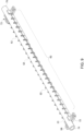
- FIG. 8 depicts an embodiment of the interface 24.
- the depicted interface 24 includes the backbone structure 62 with spaced-apart ribs 52 and the oscillator mount 58.
- the mounting or coupling to the oscillator 28 may be any suitable structure, and the depicted oscillator mount 58 is by way of example only.
- the structure of the interface 24 reduces the surface in direct contact with the exterior surface of the flow tube 20 in order to control the transmission of force and temperature along the oscillator.
- the ribs 52 are spaced apart to interrupt the direct contact of the interface with the flow tube 20.
- the contact area is suitable enough to permit a good oscillation/Coriolis force transmission from the oscillator 28 to the flow tube 20 via the interface 24. Further, the heat capacity is minimized to permit the flow tube 20 to quickly adapt to transient thermal events.
- the backbone structure 62 includes spaced-apart rails that are generally aligned in a direction along the flow axis 68. Further, the thickness of each rail 66 and the distance between them may vary to create different stiffness effects along the axis 70.
- FIG. 9 shows the interface 24 of FIG. 8 coupled to the flow tube 20. Clips 72 disposed at the ends of the interface 24 (e.g., on the oscillator mount 58) may provide greater retaining force at the interface oscillator mount point.
- the interface 24 may be arranged to permit overhang of the fluid entry point 74 and the fluid exit point 76 to permit coupling of the flow tube 20 to other tubing of the system 10.
- FIG. 10 shows the interface 24 of FIG. 8 fixed to an oscillator 28.
- FIG. 11-13 various embodiments of interfaces 24 for coupling the oscillator 28 to the flow tube 20 in accordance with the present disclosure.
- shape of the flow tubes 20 shown in FIGS. 11-13 is a bent shape, any shape (e.g., straight or looped) may be incorporated in a Coriolis sensing assembly in accordance with the present techniques.
- FIG. 11 shows the flow tube 20 coupled to a metal oscillator 28 by an adhesive (e.g., glue) interface 24.
- FIG. 12 shows the flow tube 20 coupled to a polymer oscillator 28 through metal clips 86.
- FIG. 13 shows the flow tube 20 coupled to a polymer oscillator 28 with a wire wrap 88.
- the sensor assemblies 14 depicted in FIGS. 11-13 may have variable performance. For example, FIG. 13 wire wrap showed superior performance relative to the metal clips and the adhesive. It should be appreciated by one of ordinary skill in the art that any combination of these techniques may be incorporated into a sensor assembly 14.
- an adhesive interface 24 may be disposed between the flow tube 20 and the oscillator 28 in addition to the wire wraps 88.
- the adhesive interface may be disposed at intervals along the direction of the flow, rather than continuously disposed.
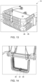
- FIGS. 14-16 shows various interfaces 24 for coupling the flow tube 20 and the oscillator 28 of a Coriolis flow sensor assembly 14 in accordance with the present disclosure.
- FIG. 14 shows a bent silicone flow tube 20 coupled to the oscillator 28 through a polymer interface 24.
- FIG. 15 shows a hybrid metal/polymer oscillator directly coupled to the silicone flow tube 20.
- the oscillator 28 includes structural features (e.g., walls) that enable the oscillator 28 and flow tube 20 to couple such that the oscillator 28 receives the flow tube 20 between the walls 54. Further, as shown, the walls 54 have a varying height, which may permit certain advantages as described herein.
- FIG. 16 shows an interface having a backbone, which demonstrated superior performance to the interfaces 24 shown in FIGS. 14-15 .
- Some applications for the disposable-part sub-system described herein include fabrication of wafers in semi-conductor industry, and medical applications that involve use of organic fluids. Some of these are high purity applications and use of flow conduit made of for example polymer, or other chemically inert material is advantageous in such applications, and in some other applications electrically inert and low thermal conductivity material like glass is advantageous.
- This disclosure relates to a sensor assembly of a Coriolis flow sensor system with an interface that permits transmission of the drive oscillation and the Coriolis force, but limits the transmission of environmental disturbances that may negatively influence the drive oscillation of the flow tube.
- the interface may be disposed between a flow tube and an oscillator of the Coriolis flow sensor system.
- the interface may be positioned between the flow tube and oscillator, disposed at the ends of a region between the flow tube and the oscillator, or at intervals along the region.
- the interface may include structural features that facilitate coupling between the interface and the oscillator (e.g., hooks, bolts, screws, adhesive material).
- a portion of the interface that receives the flow tube may be flat or may partially surround a portion of the perimeter (e.g., circumference) of the flowtube.
- the interface may include (e.g., separately or be attached to) structural components that facilitate retaining of the flow tube as well as permit coupling between the flow tube, interface, and oscillator.
Landscapes
- Physics & Mathematics (AREA)
- Fluid Mechanics (AREA)
- General Physics & Mathematics (AREA)
- Measuring Volume Flow (AREA)
Claims (14)
- Coriolis-Durchflusssensorsystem (10), umfassend:
eine Fluiddurchflussanordnung (18), umfassend:ein Durchflussrohr (20), das konfiguriert ist um einen Durchflussweg durch das Durchflussrohr (20) bereitzustellen;eine mechanische Antriebsanordnung (30), die konfiguriert ist um eine Oszillation des Durchflussrohrs (20) anzutreiben, während Fluid (22) strömt, wobei die mechanische Antriebsanordnung (30) eine Oszillationsfläche umfasst; undeine Schnittstelle (24), die fest mit der Oszillationsfläche der mechanischen Antriebsanordnung (30) gekoppelt und zur Aufnahme des Durchflussrohrs (20) konfiguriert ist, so dass mindestens ein Teil der Schnittstelle (24) in direktem Kontakt mit dem Durchflussrohr (20) steht und so dass die Schnittstelle (24) Oszillationskräfte der Oszillationsfläche auf das Durchflussrohr (20) überträgt;wobei die Oszillationsfläche der mechanischen Antriebsanordnung (30) eine Vielzahl von Verankerungspunkten (50) zur Verbindung der Schnittstelle (24) mit dieser umfasst, unddie Schnittstelle (24) mit der Fluiddurchflussanordnung (18) mit einer oder mehreren Rippenstrukturen (52) oder mit einem oder mehreren Wandmerkmalen (54) gekoppelt ist, die entlang der Schnittstelle (24) in einer Richtung des Durchflusswegs angeordnet sind. - Coriolis-Durchflusssensorsystem (10) nach Anspruch 1, wobei die Schnittstelle (24) adhäsiv mit der Oszillationsfläche gekoppelt ist.
- Coriolis-Durchflusssensorsystem (10) nach Anspruch 1 oder 2, wobei die Schnittstelle (24) das eine oder die mehreren Wandmerkmale (54) umfasst, die so konfiguriert sind, dass sie das Durchflussrohr (20) teilweise umschließen, wenn die Schnittstelle (24) die Fluiddurchflussanordnung (18) aufnimmt.
- Coriolis-Durchflusssensorsystem (10) nach Anspruch 3, wobei die Wandmerkmale (54) entlang einer Richtung des Durchflussweges eine unterschiedliche Höhe (56) aufweisen.
- Coriolis-Durchflusssensorsystem (10) nach einem vorstehenden Anspruch, wobei jede der Rippenstrukturen (52) in direktem Kontakt mit dem Durchflussrohr (20) steht.
- Coriolis-Durchflusssensorsystem (10) nach einem vorstehenden Anspruch, wobei die eine oder mehreren Rippenstrukturen (52) mehrere Rippenstrukturen (52) umfassen, die jeweils in regelmäßigen Abständen in Richtung des Durchflussweges angeordnet sind.
- Coriolis-Durchflusssensorsystem (10) nach einem vorstehenden Anspruch, wobei die Schnittstelle (24) das Durchflussrohr (20) von der Oszillationsfläche trennt, so dass das Durchflussrohr (20) nicht direkt mit einem mechanischen Oszillator (28) in Kontakt kommt.
- Coriolis-Durchflusssensorsystem (10) nach einem vorstehenden Anspruch, wobei die Schnittstelle (24) ein Rückgrat (62) mit voneinander beabstandeten Schienen (66) umfasst.
- Coriolis-Durchflusssensorsystem (10) nach einem vorstehenden Anspruch, wobei die Schnittstelle (24) eine Metallklammer umfasst, die über einen Reibschluss mit dem Durchflussrohr (20) gekoppelt ist.
- Coriolis-Durchflusssensorsystem (10) nach einem vorstehenden Anspruch, wobei die Schnittstelle (24) die mechanische Antriebsanordnung (30) über eine Drahtumwicklung mit dem Durchflussrohr (20) koppelt.
- Coriolis-Durchflusssensorsystem (10) nach einem vorstehenden Anspruch, wobei die Schnittstelle (24) weiter Klammern (72) umfasst, die an ihren jeweiligen Enden angeordnet sind.
- Coriolis-Durchflusssensorsystem (10) nach einem vorstehenden Anspruch, wobei die Schnittstelle (24) ein oder mehrere lösbare Rückhalteelemente umfasst, die so konfiguriert sind, dass sie das Durchflussrohr (20) lösbar zurückhalten.
- Coriolis-Durchflusssensorsystem (10) nach einem vorstehenden Anspruch, wobei das Durchflussrohr (20) ein Einwegprodukt ist.
- Coriolis-Durchflusssensorsystem (10) nach einem vorstehenden Anspruch, wobei die Schnittstelle (24) konfiguriert ist, um das Durchflussrohr (20) entlang einer Achse (68, 70) zu halten und/oder wobei die Schnittstelle (24) aus einem Polymer gebildet ist.
Applications Claiming Priority (2)
| Application Number | Priority Date | Filing Date | Title |
|---|---|---|---|
| US15/832,519 US10429224B2 (en) | 2017-12-05 | 2017-12-05 | Interface for a Coriolis flow sensing assembly |
| PCT/EP2018/083555 WO2019110623A1 (en) | 2017-12-05 | 2018-12-04 | Interface for a coriolis flow sensing assembly |
Publications (2)
| Publication Number | Publication Date |
|---|---|
| EP3721182A1 EP3721182A1 (de) | 2020-10-14 |
| EP3721182B1 true EP3721182B1 (de) | 2025-02-19 |
Family
ID=64604657
Family Applications (1)
| Application Number | Title | Priority Date | Filing Date |
|---|---|---|---|
| EP18814585.8A Active EP3721182B1 (de) | 2017-12-05 | 2018-12-04 | Schnittstelle für eine coriolis-durchflussmesseranordnung |
Country Status (5)
| Country | Link |
|---|---|
| US (2) | US10429224B2 (de) |
| EP (1) | EP3721182B1 (de) |
| JP (1) | JP7278620B2 (de) |
| CN (1) | CN112105896B (de) |
| WO (1) | WO2019110623A1 (de) |
Families Citing this family (3)
| Publication number | Priority date | Publication date | Assignee | Title |
|---|---|---|---|---|
| US10429224B2 (en) * | 2017-12-05 | 2019-10-01 | General Electric Company | Interface for a Coriolis flow sensing assembly |
| DE102019134608A1 (de) * | 2019-12-16 | 2021-06-17 | Endress + Hauser Flowtec Ag | Messaufnehmer eines Messgerätes |
| DE102019134600A1 (de) * | 2019-12-16 | 2021-06-17 | Endress + Hauser Flowtec Ag | Messaufnehmer und Coriolis-Messgerät |
Family Cites Families (27)
| Publication number | Priority date | Publication date | Assignee | Title |
|---|---|---|---|---|
| US4738144A (en) | 1986-10-03 | 1988-04-19 | Micro Motion, Inc. | Drive means for oscillating flow tubes of parallel path coriolis mass flow rate meter |
| US5115683A (en) | 1988-09-27 | 1992-05-26 | K-Flow Division Of Kane Steel Co., Inc. | Coriolis mass flow meter adapted for low flow rates |
| BR9206318A (pt) | 1991-08-01 | 1995-10-24 | Micro Motion Inc | Medidor de fluxo de massa de efeito coriolis |
| JP3251374B2 (ja) * | 1993-03-17 | 2002-01-28 | 株式会社オーバル | メディカル用コリオリ流量計 |
| DE4311694C1 (de) | 1993-04-08 | 1994-09-29 | Fritz Giebler Gmbh | Durchflußmesser |
| US5691485A (en) * | 1994-06-06 | 1997-11-25 | Oval Corporation | Coaxial double tube type Coriolis flowmeter |
| US5497666A (en) * | 1994-07-20 | 1996-03-12 | Micro Motion, Inc. | Increased sensitivity coriolis effect flowmeter using nodal-proximate sensors |
| US5555190A (en) | 1995-07-12 | 1996-09-10 | Micro Motion, Inc. | Method and apparatus for adaptive line enhancement in Coriolis mass flow meter measurement |
| EP0871017B1 (de) * | 1997-04-10 | 2008-07-30 | Endress + Hauser Flowtec AG | Coriolis-Massedurchflussaufnehmer mit einem Messrohr |
| TW399146B (en) * | 1998-05-29 | 2000-07-21 | Oval Corp | Coliolis mass flowmeter |
| US6748813B1 (en) * | 1998-12-08 | 2004-06-15 | Emerson Electric Company | Coriolis mass flow controller |
| JP4565150B2 (ja) * | 2003-05-12 | 2010-10-20 | 独立行政法人産業技術総合研究所 | コリオリ流量計 |
| CN101014837A (zh) * | 2004-07-15 | 2007-08-08 | Pdc设备公司 | 用于流量计的衬管 |
| US7617055B2 (en) * | 2006-08-28 | 2009-11-10 | Invensys Systems, Inc. | Wet gas measurement |
| NL1032824C2 (nl) | 2006-11-07 | 2008-05-14 | Ccm Beheer Bv | Inrichting en werkwijze voor het meten van dichtheid en/of massastroom van een fluïdum. |
| KR101201391B1 (ko) * | 2007-07-30 | 2012-11-20 | 마이크로 모우션, 인코포레이티드 | 삼상 유동의 유동 특성을 측정하기 위한 진동 유량계 시스템 및 방법 |
| JP5039654B2 (ja) * | 2008-07-09 | 2012-10-03 | 株式会社キーエンス | 流量計 |
| EP2435800A1 (de) * | 2009-05-26 | 2012-04-04 | Micro Motion, Inc. | Durchflussmesser mit ausgleichselement |
| DE102009028006A1 (de) * | 2009-07-24 | 2011-01-27 | Endress + Hauser Flowtec Ag | Meßwandler vom Vibrationstyp sowie Meßgerät mit einem solchen Meßwandler |
| MX2014007779A (es) * | 2012-01-10 | 2014-09-15 | Micro Motion Inc | Dispositivo y metodo de servicio de campo para facilitar un reemplazo de sistema de procesamiento en un flujometro vibratorio. |
| JP6416092B2 (ja) * | 2012-08-21 | 2018-10-31 | マイクロ モーション インコーポレイテッド | 改良されたメータゼロに関するコリオリ流量計および方法 |
| JP2013136461A (ja) * | 2013-02-27 | 2013-07-11 | Micro Motion Inc | 振動式流れデバイスおよび振動式流れデバイスを製作するための方法 |
| US20150377673A1 (en) | 2014-06-30 | 2015-12-31 | General Electric Company | Coriolis flow meter and method of measuring mass flow rate |
| DE102015118347A1 (de) * | 2015-10-27 | 2017-04-27 | Endress+Hauser Flowtec Ag | Messaufnehmer mit einer zu Schwingungen anregbaren Messleitung |
| DE102016100952A1 (de) | 2016-01-20 | 2017-07-20 | Krohne Messtechnik Gmbh | Verfahren zum Betreiben eines Coriolis-Massedurchflussmessgeräts und entsprechendes Coriolis-Massedurchflussmessgerät |
| JP6178033B1 (ja) * | 2017-04-03 | 2017-08-09 | 株式会社アツデン | コリオリ式質量流量計 |
| US10429224B2 (en) * | 2017-12-05 | 2019-10-01 | General Electric Company | Interface for a Coriolis flow sensing assembly |
-
2017
- 2017-12-05 US US15/832,519 patent/US10429224B2/en active Active
-
2018
- 2018-12-04 US US16/768,956 patent/US11428558B2/en active Active
- 2018-12-04 WO PCT/EP2018/083555 patent/WO2019110623A1/en not_active Ceased
- 2018-12-04 JP JP2020530693A patent/JP7278620B2/ja active Active
- 2018-12-04 CN CN201880078478.2A patent/CN112105896B/zh active Active
- 2018-12-04 EP EP18814585.8A patent/EP3721182B1/de active Active
Also Published As
| Publication number | Publication date |
|---|---|
| US10429224B2 (en) | 2019-10-01 |
| WO2019110623A1 (en) | 2019-06-13 |
| EP3721182A1 (de) | 2020-10-14 |
| CN112105896B (zh) | 2024-02-27 |
| US20210223079A1 (en) | 2021-07-22 |
| JP2021505881A (ja) | 2021-02-18 |
| US11428558B2 (en) | 2022-08-30 |
| JP7278620B2 (ja) | 2023-05-22 |
| US20190170554A1 (en) | 2019-06-06 |
| CN112105896A (zh) | 2020-12-18 |
Similar Documents
| Publication | Publication Date | Title |
|---|---|---|
| JP4426746B2 (ja) | 保護外層を備えたケーシングを有するコリオリ流量計 | |
| EP0733886A2 (de) | Coriolis-Massendurchflussmesser | |
| CN101084416B (zh) | 振动型测量变送器 | |
| CN100565127C (zh) | 振动传感器 | |
| US11428558B2 (en) | Coriolis flow sensor systems with an interface coupling an oscillator to a flow tube | |
| US8931354B2 (en) | Coriolis mass flow meter with high zero stability | |
| JP5888330B2 (ja) | 対称共振器を有する流体特性測定装置 | |
| WO1996008697A2 (en) | Mass flowmeter and conduit assembly | |
| WO2005010467A2 (en) | Vibrating tube mass flow meter | |
| CN103124898B (zh) | 包括阻尼计量部件的振动计 | |
| RU2502055C2 (ru) | Способ и устройство для соединения корпуса с вибрационным расходомером | |
| JP7271044B2 (ja) | コリオリ流量センサアセンブリ | |
| EP1790955B1 (de) | Coriolis-strömungsmesser des tertiärmodenvibrationstyps | |
| RU2314498C2 (ru) | Расходомер кориолиса и способ работы расходомера кориолиса | |
| WO2020248231A1 (en) | Averaging pitot tube having adjustable resonant frequency | |
| US10598531B2 (en) | Coriolis flow meter with multiple actuators arranged on a flow tube and driven in different planes | |
| JP3593513B2 (ja) | 弓形管式コリオリメータ及びその形状決定方法 | |
| NL2012498B1 (en) | Coriolis flowsensor. | |
| HK1171077B (en) | Method and apparatus for coupling a case to a vibrating flow meter | |
| HK1185938A (en) | A vibrating meter including a damped meter component | |
| HK1185938B (en) | A vibrating meter including a damped meter component | |
| HK1026021A1 (en) | Coriolis flowmeter having axially compliant case ends |
Legal Events
| Date | Code | Title | Description |
|---|---|---|---|
| STAA | Information on the status of an ep patent application or granted ep patent |
Free format text: STATUS: UNKNOWN |
|
| STAA | Information on the status of an ep patent application or granted ep patent |
Free format text: STATUS: THE INTERNATIONAL PUBLICATION HAS BEEN MADE |
|
| PUAI | Public reference made under article 153(3) epc to a published international application that has entered the european phase |
Free format text: ORIGINAL CODE: 0009012 |
|
| STAA | Information on the status of an ep patent application or granted ep patent |
Free format text: STATUS: REQUEST FOR EXAMINATION WAS MADE |
|
| 17P | Request for examination filed |
Effective date: 20200520 |
|
| AK | Designated contracting states |
Kind code of ref document: A1 Designated state(s): AL AT BE BG CH CY CZ DE DK EE ES FI FR GB GR HR HU IE IS IT LI LT LU LV MC MK MT NL NO PL PT RO RS SE SI SK SM TR |
|
| AX | Request for extension of the european patent |
Extension state: BA ME |
|
| DAV | Request for validation of the european patent (deleted) | ||
| DAX | Request for extension of the european patent (deleted) | ||
| STAA | Information on the status of an ep patent application or granted ep patent |
Free format text: STATUS: EXAMINATION IS IN PROGRESS |
|
| 17Q | First examination report despatched |
Effective date: 20221017 |
|
| P01 | Opt-out of the competence of the unified patent court (upc) registered |
Effective date: 20230526 |
|
| GRAP | Despatch of communication of intention to grant a patent |
Free format text: ORIGINAL CODE: EPIDOSNIGR1 |
|
| STAA | Information on the status of an ep patent application or granted ep patent |
Free format text: STATUS: GRANT OF PATENT IS INTENDED |
|
| RIC1 | Information provided on ipc code assigned before grant |
Ipc: G01F 15/02 20060101ALI20240618BHEP Ipc: G01F 1/84 20060101AFI20240618BHEP |
|
| INTG | Intention to grant announced |
Effective date: 20240712 |
|
| GRAJ | Information related to disapproval of communication of intention to grant by the applicant or resumption of examination proceedings by the epo deleted |
Free format text: ORIGINAL CODE: EPIDOSDIGR1 |
|
| STAA | Information on the status of an ep patent application or granted ep patent |
Free format text: STATUS: EXAMINATION IS IN PROGRESS |
|
| INTC | Intention to grant announced (deleted) | ||
| GRAP | Despatch of communication of intention to grant a patent |
Free format text: ORIGINAL CODE: EPIDOSNIGR1 |
|
| STAA | Information on the status of an ep patent application or granted ep patent |
Free format text: STATUS: GRANT OF PATENT IS INTENDED |
|
| INTG | Intention to grant announced |
Effective date: 20240919 |
|
| GRAS | Grant fee paid |
Free format text: ORIGINAL CODE: EPIDOSNIGR3 |
|
| GRAA | (expected) grant |
Free format text: ORIGINAL CODE: 0009210 |
|
| STAA | Information on the status of an ep patent application or granted ep patent |
Free format text: STATUS: THE PATENT HAS BEEN GRANTED |
|
| AK | Designated contracting states |
Kind code of ref document: B1 Designated state(s): AL AT BE BG CH CY CZ DE DK EE ES FI FR GB GR HR HU IE IS IT LI LT LU LV MC MK MT NL NO PL PT RO RS SE SI SK SM TR |
|
| REG | Reference to a national code |
Ref country code: GB Ref legal event code: FG4D |
|
| REG | Reference to a national code |
Ref country code: CH Ref legal event code: EP |
|
| REG | Reference to a national code |
Ref country code: IE Ref legal event code: FG4D |
|
| REG | Reference to a national code |
Ref country code: DE Ref legal event code: R096 Ref document number: 602018079367 Country of ref document: DE |
|
| REG | Reference to a national code |
Ref country code: NL Ref legal event code: MP Effective date: 20250219 |
|
| PG25 | Lapsed in a contracting state [announced via postgrant information from national office to epo] |
Ref country code: RS Free format text: LAPSE BECAUSE OF FAILURE TO SUBMIT A TRANSLATION OF THE DESCRIPTION OR TO PAY THE FEE WITHIN THE PRESCRIBED TIME-LIMIT Effective date: 20250519 |
|
| PG25 | Lapsed in a contracting state [announced via postgrant information from national office to epo] |
Ref country code: FI Free format text: LAPSE BECAUSE OF FAILURE TO SUBMIT A TRANSLATION OF THE DESCRIPTION OR TO PAY THE FEE WITHIN THE PRESCRIBED TIME-LIMIT Effective date: 20250219 |
|
| PG25 | Lapsed in a contracting state [announced via postgrant information from national office to epo] |
Ref country code: PL Free format text: LAPSE BECAUSE OF FAILURE TO SUBMIT A TRANSLATION OF THE DESCRIPTION OR TO PAY THE FEE WITHIN THE PRESCRIBED TIME-LIMIT Effective date: 20250219 |
|
| PG25 | Lapsed in a contracting state [announced via postgrant information from national office to epo] |
Ref country code: ES Free format text: LAPSE BECAUSE OF FAILURE TO SUBMIT A TRANSLATION OF THE DESCRIPTION OR TO PAY THE FEE WITHIN THE PRESCRIBED TIME-LIMIT Effective date: 20250219 |
|
| REG | Reference to a national code |
Ref country code: LT Ref legal event code: MG9D |
|
| PG25 | Lapsed in a contracting state [announced via postgrant information from national office to epo] |
Ref country code: IS Free format text: LAPSE BECAUSE OF FAILURE TO SUBMIT A TRANSLATION OF THE DESCRIPTION OR TO PAY THE FEE WITHIN THE PRESCRIBED TIME-LIMIT Effective date: 20250619 Ref country code: NO Free format text: LAPSE BECAUSE OF FAILURE TO SUBMIT A TRANSLATION OF THE DESCRIPTION OR TO PAY THE FEE WITHIN THE PRESCRIBED TIME-LIMIT Effective date: 20250519 |
|
| PG25 | Lapsed in a contracting state [announced via postgrant information from national office to epo] |
Ref country code: NL Free format text: LAPSE BECAUSE OF FAILURE TO SUBMIT A TRANSLATION OF THE DESCRIPTION OR TO PAY THE FEE WITHIN THE PRESCRIBED TIME-LIMIT Effective date: 20250219 |
|
| PG25 | Lapsed in a contracting state [announced via postgrant information from national office to epo] |
Ref country code: HR Free format text: LAPSE BECAUSE OF FAILURE TO SUBMIT A TRANSLATION OF THE DESCRIPTION OR TO PAY THE FEE WITHIN THE PRESCRIBED TIME-LIMIT Effective date: 20250219 |
|
| PG25 | Lapsed in a contracting state [announced via postgrant information from national office to epo] |
Ref country code: LV Free format text: LAPSE BECAUSE OF FAILURE TO SUBMIT A TRANSLATION OF THE DESCRIPTION OR TO PAY THE FEE WITHIN THE PRESCRIBED TIME-LIMIT Effective date: 20250219 Ref country code: PT Free format text: LAPSE BECAUSE OF FAILURE TO SUBMIT A TRANSLATION OF THE DESCRIPTION OR TO PAY THE FEE WITHIN THE PRESCRIBED TIME-LIMIT Effective date: 20250620 |
|
| PG25 | Lapsed in a contracting state [announced via postgrant information from national office to epo] |
Ref country code: BG Free format text: LAPSE BECAUSE OF FAILURE TO SUBMIT A TRANSLATION OF THE DESCRIPTION OR TO PAY THE FEE WITHIN THE PRESCRIBED TIME-LIMIT Effective date: 20250219 Ref country code: GR Free format text: LAPSE BECAUSE OF FAILURE TO SUBMIT A TRANSLATION OF THE DESCRIPTION OR TO PAY THE FEE WITHIN THE PRESCRIBED TIME-LIMIT Effective date: 20250520 |
|
| REG | Reference to a national code |
Ref country code: AT Ref legal event code: MK05 Ref document number: 1768650 Country of ref document: AT Kind code of ref document: T Effective date: 20250219 |
|
| PG25 | Lapsed in a contracting state [announced via postgrant information from national office to epo] |
Ref country code: SE Free format text: LAPSE BECAUSE OF FAILURE TO SUBMIT A TRANSLATION OF THE DESCRIPTION OR TO PAY THE FEE WITHIN THE PRESCRIBED TIME-LIMIT Effective date: 20250219 |
|
| PG25 | Lapsed in a contracting state [announced via postgrant information from national office to epo] |
Ref country code: SM Free format text: LAPSE BECAUSE OF FAILURE TO SUBMIT A TRANSLATION OF THE DESCRIPTION OR TO PAY THE FEE WITHIN THE PRESCRIBED TIME-LIMIT Effective date: 20250219 |
|
| PG25 | Lapsed in a contracting state [announced via postgrant information from national office to epo] |
Ref country code: DK Free format text: LAPSE BECAUSE OF FAILURE TO SUBMIT A TRANSLATION OF THE DESCRIPTION OR TO PAY THE FEE WITHIN THE PRESCRIBED TIME-LIMIT Effective date: 20250219 |
|
| PG25 | Lapsed in a contracting state [announced via postgrant information from national office to epo] |
Ref country code: IT Free format text: LAPSE BECAUSE OF FAILURE TO SUBMIT A TRANSLATION OF THE DESCRIPTION OR TO PAY THE FEE WITHIN THE PRESCRIBED TIME-LIMIT Effective date: 20250219 |
|
| PG25 | Lapsed in a contracting state [announced via postgrant information from national office to epo] |
Ref country code: AT Free format text: LAPSE BECAUSE OF FAILURE TO SUBMIT A TRANSLATION OF THE DESCRIPTION OR TO PAY THE FEE WITHIN THE PRESCRIBED TIME-LIMIT Effective date: 20250219 |
|
| PG25 | Lapsed in a contracting state [announced via postgrant information from national office to epo] |
Ref country code: EE Free format text: LAPSE BECAUSE OF FAILURE TO SUBMIT A TRANSLATION OF THE DESCRIPTION OR TO PAY THE FEE WITHIN THE PRESCRIBED TIME-LIMIT Effective date: 20250219 Ref country code: CZ Free format text: LAPSE BECAUSE OF FAILURE TO SUBMIT A TRANSLATION OF THE DESCRIPTION OR TO PAY THE FEE WITHIN THE PRESCRIBED TIME-LIMIT Effective date: 20250219 |
|
| PG25 | Lapsed in a contracting state [announced via postgrant information from national office to epo] |
Ref country code: RO Free format text: LAPSE BECAUSE OF FAILURE TO SUBMIT A TRANSLATION OF THE DESCRIPTION OR TO PAY THE FEE WITHIN THE PRESCRIBED TIME-LIMIT Effective date: 20250219 |
|
| PG25 | Lapsed in a contracting state [announced via postgrant information from national office to epo] |
Ref country code: SK Free format text: LAPSE BECAUSE OF FAILURE TO SUBMIT A TRANSLATION OF THE DESCRIPTION OR TO PAY THE FEE WITHIN THE PRESCRIBED TIME-LIMIT Effective date: 20250219 |
|
| REG | Reference to a national code |
Ref country code: DE Ref legal event code: R097 Ref document number: 602018079367 Country of ref document: DE |
|
| PLBE | No opposition filed within time limit |
Free format text: ORIGINAL CODE: 0009261 |
|
| STAA | Information on the status of an ep patent application or granted ep patent |
Free format text: STATUS: NO OPPOSITION FILED WITHIN TIME LIMIT |
|
| PGFP | Annual fee paid to national office [announced via postgrant information from national office to epo] |
Ref country code: GB Payment date: 20251223 Year of fee payment: 8 |
|
| PGFP | Annual fee paid to national office [announced via postgrant information from national office to epo] |
Ref country code: FR Payment date: 20251230 Year of fee payment: 8 |
|
| 26N | No opposition filed |
Effective date: 20251120 |
|
| PGFP | Annual fee paid to national office [announced via postgrant information from national office to epo] |
Ref country code: DE Payment date: 20251229 Year of fee payment: 8 |