EP3720522B1 - Drug delivery device - Google Patents
Drug delivery device Download PDFInfo
- Publication number
- EP3720522B1 EP3720522B1 EP18819061.5A EP18819061A EP3720522B1 EP 3720522 B1 EP3720522 B1 EP 3720522B1 EP 18819061 A EP18819061 A EP 18819061A EP 3720522 B1 EP3720522 B1 EP 3720522B1
- Authority
- EP
- European Patent Office
- Prior art keywords
- drug delivery
- delivery device
- liquid
- chamber portion
- plunger
- Prior art date
- Legal status (The legal status is an assumption and is not a legal conclusion. Google has not performed a legal analysis and makes no representation as to the accuracy of the status listed.)
- Active
Links
Images


Classifications
-
- A—HUMAN NECESSITIES
- A61—MEDICAL OR VETERINARY SCIENCE; HYGIENE
- A61M—DEVICES FOR INTRODUCING MEDIA INTO, OR ONTO, THE BODY; DEVICES FOR TRANSDUCING BODY MEDIA OR FOR TAKING MEDIA FROM THE BODY; DEVICES FOR PRODUCING OR ENDING SLEEP OR STUPOR
- A61M5/00—Devices for bringing media into the body in a subcutaneous, intra-vascular or intramuscular way; Accessories therefor, e.g. filling or cleaning devices, arm-rests
- A61M5/14—Infusion devices, e.g. infusing by gravity; Blood infusion; Accessories therefor
- A61M5/168—Means for controlling media flow to the body or for metering media to the body, e.g. drip meters, counters ; Monitoring media flow to the body
- A61M5/16804—Flow controllers
- A61M5/16809—Flow controllers by repeated filling and emptying of an intermediate volume
-
- A—HUMAN NECESSITIES
- A61—MEDICAL OR VETERINARY SCIENCE; HYGIENE
- A61M—DEVICES FOR INTRODUCING MEDIA INTO, OR ONTO, THE BODY; DEVICES FOR TRANSDUCING BODY MEDIA OR FOR TAKING MEDIA FROM THE BODY; DEVICES FOR PRODUCING OR ENDING SLEEP OR STUPOR
- A61M5/00—Devices for bringing media into the body in a subcutaneous, intra-vascular or intramuscular way; Accessories therefor, e.g. filling or cleaning devices, arm-rests
- A61M5/14—Infusion devices, e.g. infusing by gravity; Blood infusion; Accessories therefor
- A61M5/142—Pressure infusion, e.g. using pumps
- A61M5/14244—Pressure infusion, e.g. using pumps adapted to be carried by the patient, e.g. portable on the body
- A61M5/14248—Pressure infusion, e.g. using pumps adapted to be carried by the patient, e.g. portable on the body of the skin patch type
-
- A—HUMAN NECESSITIES
- A61—MEDICAL OR VETERINARY SCIENCE; HYGIENE
- A61M—DEVICES FOR INTRODUCING MEDIA INTO, OR ONTO, THE BODY; DEVICES FOR TRANSDUCING BODY MEDIA OR FOR TAKING MEDIA FROM THE BODY; DEVICES FOR PRODUCING OR ENDING SLEEP OR STUPOR
- A61M5/00—Devices for bringing media into the body in a subcutaneous, intra-vascular or intramuscular way; Accessories therefor, e.g. filling or cleaning devices, arm-rests
- A61M5/14—Infusion devices, e.g. infusing by gravity; Blood infusion; Accessories therefor
- A61M5/142—Pressure infusion, e.g. using pumps
- A61M5/145—Pressure infusion, e.g. using pumps using pressurised reservoirs, e.g. pressurised by means of pistons
- A61M5/1452—Pressure infusion, e.g. using pumps using pressurised reservoirs, e.g. pressurised by means of pistons pressurised by means of pistons
-
- A—HUMAN NECESSITIES
- A61—MEDICAL OR VETERINARY SCIENCE; HYGIENE
- A61M—DEVICES FOR INTRODUCING MEDIA INTO, OR ONTO, THE BODY; DEVICES FOR TRANSDUCING BODY MEDIA OR FOR TAKING MEDIA FROM THE BODY; DEVICES FOR PRODUCING OR ENDING SLEEP OR STUPOR
- A61M5/00—Devices for bringing media into the body in a subcutaneous, intra-vascular or intramuscular way; Accessories therefor, e.g. filling or cleaning devices, arm-rests
- A61M5/14—Infusion devices, e.g. infusing by gravity; Blood infusion; Accessories therefor
- A61M5/142—Pressure infusion, e.g. using pumps
- A61M5/14244—Pressure infusion, e.g. using pumps adapted to be carried by the patient, e.g. portable on the body
- A61M2005/14268—Pressure infusion, e.g. using pumps adapted to be carried by the patient, e.g. portable on the body with a reusable and a disposable component
-
- A—HUMAN NECESSITIES
- A61—MEDICAL OR VETERINARY SCIENCE; HYGIENE
- A61M—DEVICES FOR INTRODUCING MEDIA INTO, OR ONTO, THE BODY; DEVICES FOR TRANSDUCING BODY MEDIA OR FOR TAKING MEDIA FROM THE BODY; DEVICES FOR PRODUCING OR ENDING SLEEP OR STUPOR
- A61M5/00—Devices for bringing media into the body in a subcutaneous, intra-vascular or intramuscular way; Accessories therefor, e.g. filling or cleaning devices, arm-rests
- A61M5/178—Syringes
- A61M5/31—Details
- A61M5/315—Pistons; Piston-rods; Guiding, blocking or restricting the movement of the rod or piston; Appliances on the rod for facilitating dosing ; Dosing mechanisms
- A61M5/31511—Piston or piston-rod constructions, e.g. connection of piston with piston-rod
- A61M2005/31518—Piston or piston-rod constructions, e.g. connection of piston with piston-rod designed to reduce the overall size of an injection device, e.g. using flexible or pivotally connected chain-like rod members
-
- A—HUMAN NECESSITIES
- A61—MEDICAL OR VETERINARY SCIENCE; HYGIENE
- A61M—DEVICES FOR INTRODUCING MEDIA INTO, OR ONTO, THE BODY; DEVICES FOR TRANSDUCING BODY MEDIA OR FOR TAKING MEDIA FROM THE BODY; DEVICES FOR PRODUCING OR ENDING SLEEP OR STUPOR
- A61M2205/00—General characteristics of the apparatus
- A61M2205/02—General characteristics of the apparatus characterised by a particular materials
- A61M2205/0216—Materials providing elastic properties, e.g. for facilitating deformation and avoid breaking
-
- A—HUMAN NECESSITIES
- A61—MEDICAL OR VETERINARY SCIENCE; HYGIENE
- A61M—DEVICES FOR INTRODUCING MEDIA INTO, OR ONTO, THE BODY; DEVICES FOR TRANSDUCING BODY MEDIA OR FOR TAKING MEDIA FROM THE BODY; DEVICES FOR PRODUCING OR ENDING SLEEP OR STUPOR
- A61M2205/00—General characteristics of the apparatus
- A61M2205/10—General characteristics of the apparatus with powered movement mechanisms
-
- A—HUMAN NECESSITIES
- A61—MEDICAL OR VETERINARY SCIENCE; HYGIENE
- A61M—DEVICES FOR INTRODUCING MEDIA INTO, OR ONTO, THE BODY; DEVICES FOR TRANSDUCING BODY MEDIA OR FOR TAKING MEDIA FROM THE BODY; DEVICES FOR PRODUCING OR ENDING SLEEP OR STUPOR
- A61M2205/00—General characteristics of the apparatus
- A61M2205/33—Controlling, regulating or measuring
- A61M2205/3331—Pressure; Flow
-
- A—HUMAN NECESSITIES
- A61—MEDICAL OR VETERINARY SCIENCE; HYGIENE
- A61M—DEVICES FOR INTRODUCING MEDIA INTO, OR ONTO, THE BODY; DEVICES FOR TRANSDUCING BODY MEDIA OR FOR TAKING MEDIA FROM THE BODY; DEVICES FOR PRODUCING OR ENDING SLEEP OR STUPOR
- A61M5/00—Devices for bringing media into the body in a subcutaneous, intra-vascular or intramuscular way; Accessories therefor, e.g. filling or cleaning devices, arm-rests
- A61M5/14—Infusion devices, e.g. infusing by gravity; Blood infusion; Accessories therefor
- A61M5/142—Pressure infusion, e.g. using pumps
- A61M5/14212—Pumping with an aspiration and an expulsion action
- A61M5/14228—Pumping with an aspiration and an expulsion action with linear peristaltic action, i.e. comprising at least three pressurising members or a helical member
Definitions
- This invention relates to a drug delivery device, in particular for the transcutaneous administration of a liquid drug.
- Certain drug delivery devices for transcutaneous administration of a drug are available on the market.
- Certain drug delivery devices are intended for use as a patch unit to be worn by the patient.
- such devices comprise a disposable unit with an adhesive patch that is arranged for temporarily bonding against the skin of a patient, the disposable unit having a needle, or catheter connected to a needle, that is injected through the patient's skin for transcutaneous administration of a liquid medicament.
- Certain devices comprise a reusable drive unit separably mounted to the disposable unit for reuse with other disposable units, the reusable unit containing an electrical motor drive for pumping the liquid medicament and control electronics.
- There are many drugs that may be administered using a patch pump unit one of the most widespread applications being for the injection of insulin to diabetes patients.
- piston pumps typically comprise a motor coupled to a linear actuator that pushes a plunger of a cartridge reservoir containing the liquid medicament.
- An example of such a device is known from EP 2 698 178 A2 , in particular, figure 9, which may feature a stepper motor driven pump.
- the displacement of the linear actuator may be very precise, particularly considering the high reduction between the motor and the linear displacement element, typically driven by a screw coupled to a rotor of the motor.
- Linear piston pumps are very accurate and reliable over a certain number of pumping cycles, however there may be variations between one pumping cycle and the next. These variations occur due to the compressible nature of the plunger that is driven by the actuator and the stick-slip effect due to friction between the plunger which is typically made of an elastomeric material and the walls of the reservoir. In the case of concentrated medicaments, such variations may not meet the required accuracy taking into account the concentration of the drug.
- many existing piston pump mechanisms are too large to provide comfort to the user.
- a pumping system that does not require a transfer of drug and that can be used with standard cartridges or vials in which the medicament is typically supplied. It is known for instance to provide vials that are equipped with a plunger that can be displaced in order to allow delivery of the medicament out of the vial.
- a drug delivery device comprising a pumping system and a liquid reservoir fluidly connected to a delivery system outlet, the liquid reservoir comprising an elastic plunger sealingly slidable within a rigid container wall of the liquid reservoir for expelling liquid out of the reservoir.
- the pumping system comprises a piston pump comprising an electrically driven plunger actuator arranged to displace the plunger a predefined distance per pump cycle, and a dosing unit arranged downstream of the liquid reservoir and fluidly connected to the liquid reservoir.
- the dosing unit comprises a chamber portion arranged between an inlet valve and an outlet valve, the chamber portion arranged to receive from the liquid reservoir a discrete pump cycle volume of liquid under an operational pressure generated by the piston pump greater than ambient pressure, and to the deliver said discrete pump cycle volume of liquid to the delivery system outlet, said pump cycle volume being dependent on the operational pressure.
- the dosing unit comprises or is in the form of a peristaltic pumping unit.
- the chamber portion is elastically expandable at least in a state when filled with a pump cycle volume of liquid.
- an elastic property of the elastic expandable chamber portion defined by a volume change ⁇ V multiplied by an operational pressure greater than ambient pressure ⁇ P is in a range of: 5 ⁇ 10 -8 ⁇ ⁇ V ⁇ ⁇ P ⁇ 1 ⁇ 10 -3 [m 3 Pa], more preferably in a range of 5 ⁇ 10 -6 ⁇ ⁇ V ⁇ ⁇ P ⁇ 1 ⁇ 10 -4 [m 3 Pa].
- the operational pressure is in a range between 10 and 1600 millibars over ambient pressure, preferably in a range of 100 to 1000 millibars.
- the operational pressure may advantageously be in a range of 500 to1000 millibars.
- the dosing unit comprises a flexible tube incorporating the chamber portion.
- the chamber portion comprises top and bottom walls that lie against each other when the chamber portion is empty, and that separate apart as the chamber portion is filled with liquid, the bottom wall resting against a base of the dosing unit.
- the bottom wall may be bonded to the base along at least portions of the perimeter of the bottom wall or at least portions distributed over the surface of the bottom wall such that when liquid is injected into the chamber portion and the top wall moves away from the bottom wall, an elastic tensile stress is generated in the top wall of the chamber portion.
- the inlet and outlet valves are in the form of pinch valves.
- the drug delivery device comprises a pump chamber actuator arranged to bias against the chamber portion to expel liquid out of the chamber portion to deliver said pump cycle volume of liquid to the delivery system outlet.
- the pump chamber actuator may be spring biased and/or actively driven by an electrical actuator.
- the plunger actuator comprises an actuation rod formed of a curved spring sheet beam, the actuation rod being bent around a U-shape.
- the U-Shape bent portion of the actuation rod is slidably guided in a housing guide slot of the housing.
- a housing portion forming the housing guide slot in which the actuation rod slides is made of a polymer.
- the polymer is Polytetrafluoroethylene (PTFE).
- the housing guide slot comprises roller bearings mounted along the guide slot on a convex side of the bent section.
- the housing guide slot is made integrally with the housing of injected polymer.
- the actuation rod is made of a tape of spring metal.
- the spring metal is a stainless steel alloy.
- the plunger actuator comprises a linear actuator and a bent actuation rod coupled at a first end to the linear actuator and at a second end to the plunger, the linear actuator being arranged parallel and laterally adjacent to the liquid reservoir.
- the linear actuator comprises a linear screw and a nut blocked in rotation and slidably movable upon rotation of the screw.
- the liquid reservoir, dosing unit, and drug outlet form part of a disposable part of the drug delivery device connectable and separable from a reusable part of the drug delivery device, the reusable part comprising the plunger actuator, a control system for controlling the pump system, and an electrical drive unit coupled to the plunger actuator.
- the dosing unit is configured such that a minimal number of 100 cycles must be performed for the dosing unit to empty the cartridge.
- Also disclosed herein is a method of operating a drug delivery device as set forth above comprising the steps of:
- the operational pressure may be greater or smaller than a target pressure due to a predefined target volume of liquid being filled in the chamber portion, said target volume being considered as the fill volume of the chamber portion at a target pressure without any pressure exerted by a pump chamber actuator.
- the target pressure may be ambient pressure, whereby when the chamber portion is filled with a predefined target volume, the chamber walls are not elastically stressed and do not exert per se any compression on the liquid therein. Thus, the operational pressure is always greater than said target pressure.
- the chamber portion wall is under elastic tension already from the initial filling of liquid such that at a predefined target volume, the chamber portion wall exerts pressure on the liquid within the chamber portion.
- the operational pressure may be situated around the target pressure, either less than the target pressure, or greater than the target pressure.
- the operational pressure in the chamber portion in step b) is in a range of between 10 and 1600 millibars over ambient pressure, preferably in a range between 100 and 1000 millibars over ambient pressure.
- the operational pressure is in a range between 500 and 1000 millibars over ambient pressure.
- said pump cycle volume of liquid is in a range of 1% to 50%, preferably in a range of 2% to 30% greater than a predefined the maximum volume of the chamber portion at ambient pressure. This additional volume over the maximum volume is obtained by elastic expansion of the wall of the chamber portion.
- the chamber portion may be pressed flat by the pump chamber actuator, for instance by a pre-stressed spring biased pump chamber actuator, such that the volume at ambient pressure inside the chamber is essentially zero due to the pressure exerted by the pump chamber actuator.
- a drug delivery device 1 includes a delivery system outlet 12 comprising a transcutaneous needle or a catheter tube for connection to a transcutaneous needle, a liquid reservoir 7 containing a medicament to be administered to a patient, a pumping system, and an electronic control and power supply system (not shown).
- the pumping system according to the invention comprises a piston pump 5 acting upon the liquid reservoir 7 and a dosing unit 6 interconnecting the liquid reservoir 7 to the delivery system outlet 12.
- the drug delivery device may comprise a multi-use reusable portion 2 and a single-use disposable portion 3 separable from the reusable part.
- the drug delivery device may be in the form of a patch pump device for mounting against the patient's skin with a transcutaneous needle fixed directly to the disposable parts and injectable through the patient's skin.
- the drug delivery device however includes embodiments that are not in the form of patch units, for example in the form of a portable autonomous device that may be carried by the patient on a belt, in a pocket or bag, or placed on a table and connected for instance via a catheter to the patient.
- Embodiments may also include a drug delivery device for bolus administration of a medicament that is temporarily placed against a patient's skin at the time of administering the bolus dose and removed from the patient after or between administrations of a dose.
- the disposable part 2 may comprise a housing support with an adhesive base for bonding to the patient's skin.
- the electronic control and power supply systems (not shown) may advantageously be mounted in the reusable part 2.
- a drive unit 11 comprising an electrical motor 42 for driving a plunger actuator of the piston pump 5 may be mounted in the reusable part 3.
- the components mounted in the disposable part may include the liquid reservoir 7, the dosing unit 6, the delivery system outlet 12 and the liquid flow channels fluidly interconnecting the aforesaid components.
- the liquid reservoir 7 comprises a container wall 13, in particular a cylindrical container wall, hermetically sealed at one end by a plunger 14 that is sealingly and slideably movable within the container wall 13 as liquid medicament contained within the liquid reservoir is expelled.
- the other end of the container wall 13 may be provided with a cap 15 comprising a septum arranged to be pierced by a hollow needle.
- a cap with a septum instead of a cap with a septum, other fluidic connection systems such as a cap with a valve or other devices allowing liquid to flow out of the reservoir into a downstream liquid flow channel that are per se known may be provided.
- the liquid reservoir 7 including the plunger 14 and cap 15 may be a standard vial of a drug manufacturer assembled in the reusable part 3 or disposable part 2, or a custom reservoir integrated in the disposable part 2 during manufacture of the disposable part.
- the piston pump 5 comprises a plunger actuator arranged to push the plunger 14 into the container 13 thus applying pressure on the liquid contained within the reservoir 7.
- the plunger actuator comprises a linear actuator 16 comprising a screw 17 coupled to and driven in rotation by a motor 42 of the drive unit 11, and a nut 19 coupled to the screw 17, the nut 19 being blocked in rotation by a housing linear guide 38 but slidable in an axial direction A corresponding to the axis of rotation A of the screw 17.
- the screw 17 is advantageously arranged essentially parallel and laterally adjacent to a central axis of the liquid reservoir 7 as defined by the direction of displacement of the plunger 14.
- An actuation rod 30 interconnects the nut 19 to a piston plate 32 pressing against the plunger 14.
- the actuation rod 30 is a bendable rod comprising a bent section 30a forming a U shape between straight sections 30b.
- the parallel adjacent arrangement of the linear actuator 16 and liquid reservoir 7 allows to provide a particularly compact piston pump and reservoir arrangement, in particular reducing the overall length L of the piston pump arrangement so that it may be conveniently mounted within a patch pump housing in a compact arrangement.
- the bent actuation rod 30 may comprise a curved profile in an unbent state, when viewed in cross section orthogonal to the plunger displacement direction A.
- the actuation rod may be made of a spring sheet metal beam configured to generate an essentially flattened profile in cross-section along a portion of the rod that is bent around a U shape as illustrated in figure 2 .
- This configuration allows the actuation rod to be rigid in the direction of a buckling force aligned with the linear sections 30b, yet flexible in a transverse direction to allow bending into the U shaped bent portion 30b such that a force may be transmitted by the nut 19 in the plunger displacement direction A to the rod 30, the force being transmitted in the rod around the U-bend to the piston plate 32.
- the bent portion 30a may be guided in a housing guide slot 34 in a housing portion of the pumping system.
- the housing portion forming the housing guide slot 34 may advantageously be made of a low friction polymer such as Polytetrafluoroethylene (PTFE) to guide the flattened profile bent portion 30a of the actuation rod 30 as it slides in the slot 34 when the nut 19 is advanced or retracted by rotation of the screw 17.
- PTFE Polytetrafluoroethylene
- low friction guide mechanisms may be provided in variants, for instance comprising roller bearings mounted along the guide slot on a convex side of the bent section 30a.
- the actuation rod 30 may advantageously be made of a tape of spring metal such as a stainless steel alloy.
- the tape of spring metal may have the following parameters:
- the drive unit 11 may be actuated in a reverse direction to retract the nut 19 from the fully extended position P1 to the fully retracted position P2 to allow the liquid reservoir 7 and disposable part 2 of the drug delivery device to be disconnected and separated from the reusable part 3 of the drug delivery device and for coupling a new disposable part to the reusable part.
- the piston plate 32 may be advanced until it abuts the rear end of the plunger 14 invention.
- the drive unit 11 may comprise an electrical motor 42 connected to a reduction gear system 44 driving the screw 17 at a reduced rate of rotation speed compared to the rotor of the motor.
- the electrical motor may include a reduction system within the motor housing.
- the reduction gear system may also be formed of a first stage gearbox within the motor and a second stage gearbox outside of the motor, coupled to an output of the motor as illustrated in figure 2 for instance.
- Such linear actuators are per se known in the art and need not be described in further detail. It may be noted however that the linear actuator 16 may comprise other configurations per se known in the field of linear actuators, connected to the bent actuation rod 30.
- the cap 15 of the liquid reservoir 7 is fluidly connected to the dosing unit 6.
- the dosing unit comprises a hollow needle 36 that pierces through a septum of the cap 15.
- the hollow needle 36 is connected to a liquid conduit 9 of the dosing unit 6.
- the liquid conduit 9 comprises an inlet portion 18, an outlet portion 20, and therebetween a chamber portion 22.
- the dosing unit further comprises an actuation system 10 comprising an inlet valve 24 acting upon the inlet portion 18, an outlet valve 26 acting upon the outlet portion 20, and a pump chamber actuator 28 acting upon the chamber portion 22 of the liquid conduit.
- the liquid conduit may be formed of a flexible tube 9, for instance a tube made of a plastic material.
- the dosing unit further comprises a base 29 on which the chamber portion is mounted.
- the pump chamber actuator 28 may be configured to bias upon the chamber portion towards the base 29, thereby pressing the chamber portion 22 against the base 29.
- the valves 24, 26 may also be configured to bias upon the inlet and outlet portions respectively, thereby pressing them against the base 29.
- the chamber portion 22 may comprise top and bottom walls 33, 31 that may be in an essentially flat planar form lying against each other when the chamber portion is empty, for instance as illustrated in figure 4b , and that separate apart as the chamber portion is filled with liquid, for instance as illustrated in figure 4d .
- the bottom wall may rest against a base 29 of the dosing unit.
- the bottom wall may be bonded, for instance by welding or adhesive, to the base 29.
- the bottom wall 31 may be bonded to the base 29 in an arrangement configured such that when liquid is injected into the chamber portion and the top wall 33 moves away from the bottom wall 31, an elastic tensile stress is generated in the top wall 33 of the chamber portion. This elastic tension in the top wall 33 of the chamber portion 22 exerts a pressure on the liquid contained within the chamber portion.
- the bottom wall 31 is this embodiment may be bonded to the base 29 along its outer perimeter, or along portions of the outer perimeter, for instance along opposed lateral edges of the bottom wall.
- the bottom wall in variants may also be bonded to the base 29 over essentially the whole surface of the bottom wall 31 or at discrete spots or portions distributed over the bottom wall. Any bonding configuration may be employed that serves the purpose of keeping the bottom wall bonded to the base as the top wall is being tensioned by the liquid filling the chamber portion 22.
- the inlet valve, outlet valve and pump chamber actuator 24, 26, 28 may be actuated independently of each other and are configured to move between a position where the fluid channel inside the tube is closed, thus preventing flow of liquid through the tube, to an open state in which the channel in the tube is open allowing through-flow of liquid.
- the inlet and outlet valves 24, 26 may be in the form of pinch valves, comprising an actuator operable to bias against the flexible tube until the liquid channel inside the tube is in squeezed closed state, or to bias away from the squeezed closed state to allow liquid to flow through the channel in the flexible tube.
- valves per se known in the art of fluid flow systems, such as ball valves, butterfly valves, and disc check valves may be used to open and close the liquid channel.
- the chamber portion 22 of the liquid conduit 9 in a fully expanded operational state contains a pump cycle volume of liquid that determines the volume of liquid medicament that may be pumped in each cycle of the dosing unit 6 as will be better described hereinafter.
- the chamber portion 22 comprises some elasticity in its expanded operational state, that allows the pump cycle volume to vary as a function of the inlet pressure that is generated by the upstream piston pump 5.
- the drive 11 is powered to displace the nut 19 and actuation rod 30 in a pumping direction such that the piston plate 32 presses against an outer face of the plunger 14 pushing it into the reservoir container 13 and compressing the liquid contained therein.
- the inlet valve 24 is closed and prevents liquid flowing therethrough.
- the pinch valve actuator pinches the inlet section 18 of the flexible tube 9 such that the liquid channel inside the inlet section is closed.
- the inlet valve 24 is then opened as illustrated in figure 4c while the plunger 14 is being pressed into the reservoir by the plunger actuator.
- the pinch valve actuator biases away from the inlet section 18 of the flexible tube 9 such that the liquid channel inside the inlet section is opened.
- the pump chamber actuator may comprise an active electrical actuator, or may comprise a spring biased actuator that presses on the chamber portion 22 of the flexible tube.
- the chamber portion 22 comprises some elasticity in its full state configured to allow the chamber portion 22 in its full state to expand elastically as a function of the pressure that is applied to the liquid.
- An example of the elastic expansion characteristic of the chamber portion in its full state is illustrated in figure 5a , whereby the dosage volume of one pump cycle at ambient pressure (at rest) is less than the dosage volume of one pump cycle at an operational (working) pressure greater than ambient pressure.
- the elastic expansion characteristic of the chamber portion 22 may have a characteristic as illustrated in figure 5b or 5c.
- the dosage volume of one pump cycle at a predefined target pressure that is greater than ambient pressure taking into account the compression provided by the wall of the chamber portion is less or more than the dosage volume of one pump cycle at an operational (working) pressure that determines the dosage per cycle.
- the operational (working) pressure may be at a value above the predefined target pressure, or at a value below the predefined target pressure.
- the elasticity may in part or in whole be provided by the material of the flexible tube. In variants however, the elasticity may be provided in whole or in part by a spring biased actuator mounted against, or elastic sleeve mounted around, the chamber portion 22.
- liquid goes into the chamber portion 22 and the volume contained therein depends on the pressure in the reservoir 7.
- the inlet valve 24 is closed and the outlet valve 26 is opened to allow liquid to flow out through the outlet section 20 of the liquid conduit 9 as illustrated in figure 4f thus fluidly connecting the chamber portion 22 to the delivery outlet 12 of the drug delivery device.
- Liquid is ejected from the chamber portion 22, either by applying pressure on the pump chamber actuator 28 by means of an electrically driven actuator or by means of a passive spring biased element applying pressure on the pump chamber actuator 28 until the pump chamber is empty or essentially empty as illustrated in figure 4g .
- the output valve 26 is then closed such that the outlet section 20 of the liquid conduit 9 is closed and a new pump cycle may be started with the steps illustrated in figures 4b to 4h .
- the order for carrying out the pumping cycles of the piston pump and the dosing unit can also be reversed or simultaneous.
- a single motor may be used for actuating both simultaneously.
- the first or the first and subsequent second, third, fourth or more initial pumping cycles may constitute an initialization or priming operation for the drug delivery device prior to first use by the patient.
- the initialization procedure may comprise the following steps :
- the pressure in the reservoir 7 at the end of a priming operation may be stabilized, for instance in a range of between 200 and 300 millibars, for instance around 250 millibars.
- the dosing unit is configured such that a minimal number of 100 cycles must be performed for the dosing unit to empty the cartridge.
- the delivered volume of one cycle is linked to the smallest delivered volume of the drug delivery device.
- the overpressure in the liquid reservoir 7 ensures that the pump system delivers accurate volumes of liquid at each cycle with a very low variation of volume from one cycle to the next because of the auto-calibration between the dosing unit 6 and the piston pump 5.
- This auto calibration is a consequence of the elasticity of the chamber portion in its expanded operation state compared to the elasticity of the plunger 14, whereby the volume variation of the chamber portion as a function of the pressure variation, is smaller than the volume variation in the liquid reservoir 7 (due to the elasticity of the plunger 14) for the same pressure variation.
- the dosing unit thus has acts a damping system on possible pressure variations of the liquid reservoir due to the variable position of the elastic plunger subject to a stick slip effect in it's displacement.
- Another advantage of the overpressure within the reservoir 7 is the reduction of formation of bubbles due to the increased vapour saturation temperature of the liquid at pressure.
- the saturation temperature with 250 millibars of overpressure corresponds, at ambient temperatures, to an increase of about 15° Celsius.
- ambient pressure is considered to be the air pressure in the environment of use of the medical device, which is around 1 bar
- ambient temperature is considered to be the ISO standard ambient temperature of 20°C.
- a volume of liquid injected per cycle corresponds for instance to about 0.5 microliters with 250 millibars pressure (over ambient pressure) delivered by the piston pump, whereas at ambient pressure, namely when the dosing unit 6 functions as a micropump without overpressure at the inlet, the pump cycle volume is about 10 % lower, for instance around 0.45 microliters per pump cycle. This last value does not need to be very accurate which is of great advantage for economical high volume production.
- a volume of liquid injected per cycle corresponds for instance to about 0.25 microliters with 650 millibars pressure (over ambient pressure) delivered by the piston pump, whereas at the target pressure of 750 millibars, the pump cycle volume is about 10 % higher, for instance around 0.275 microliters per pump cycle. This last value does not need to be very accurate which is of great advantage for economical high volume production.
- the dosing unit achieves a stabilized (calibrated) volume of liquid delivered at each cycle that has a very low variation from one cycle to the next.
- the effects of the variable compression of the plunger 14 due to its elastic properties and the stick-slip effect of friction between the plunger and the reservoir container wall are significantly reduced by the dosing unit 6 because of the stabilized overpressure in the reservoir 7 after each pumping cycle.
- the overall volume delivered by a plurality of cycles will however depend on the displacement of the plunger 14 by the linear actuator 16 which is very accurate. Thus the drug delivery is accurate both over short and long term use.
- the overpressure provided by the combination of the piston pump and dosing unit reduces the formation of bubbles in the liquid.
- the dosing unit is essentially in the form of a peristaltic pumping unit, in particular a shuttle peristaltic pump however within the scope of the invention, the dosing unit can be in the form of various volumetric incremental pumps with the property that the delivered volume per cycle varies as a function of the inlet pressure.
- the dosing unit may comprise a membrane type of pump, whereby the elastic membrane of the pump unit has the property that the delivered volume per cycle varies as a function of the inlet pressure.
- Other membrane, peristaltic or tube pumps with elastic properties may be implemented for the dosing unit.
Landscapes
- Health & Medical Sciences (AREA)
- Vascular Medicine (AREA)
- Engineering & Computer Science (AREA)
- Anesthesiology (AREA)
- Biomedical Technology (AREA)
- Heart & Thoracic Surgery (AREA)
- Hematology (AREA)
- Life Sciences & Earth Sciences (AREA)
- Animal Behavior & Ethology (AREA)
- General Health & Medical Sciences (AREA)
- Public Health (AREA)
- Veterinary Medicine (AREA)
- Dermatology (AREA)
- Infusion, Injection, And Reservoir Apparatuses (AREA)
Description
- This invention relates to a drug delivery device, in particular for the transcutaneous administration of a liquid drug.
- Various drug delivery devices for transcutaneous administration of a drug are available on the market. Certain drug delivery devices are intended for use as a patch unit to be worn by the patient. Typically, such devices comprise a disposable unit with an adhesive patch that is arranged for temporarily bonding against the skin of a patient, the disposable unit having a needle, or catheter connected to a needle, that is injected through the patient's skin for transcutaneous administration of a liquid medicament. Certain devices comprise a reusable drive unit separably mounted to the disposable unit for reuse with other disposable units, the reusable unit containing an electrical motor drive for pumping the liquid medicament and control electronics. There are many drugs that may be administered using a patch pump unit, one of the most widespread applications being for the injection of insulin to diabetes patients.
- It is generally advantageous to provide a drug delivery device that is compact, but this advantage is particularly relevant for patch pump units that are worn by the patient in order to increase comfort to the patient. In order to decrease the size of wearable drug delivery devices, certain drugs are provided in concentrated formulations. For instance insulin may be provided in a concentrated formulation. One of the difficulties associated with the administration of concentrated drugs is however the increased need for dosage accuracy per injection cycle as well as overall in the case of multiple injection cycles. With a drug such as insulin, there may be basal as well as bolus delivery of insulin for instance after a meal.
- One of the well-known pump designs used in drug delivery devices are piston pumps. These typically comprise a motor coupled to a linear actuator that pushes a plunger of a cartridge reservoir containing the liquid medicament. An example of such a device is known from
EP 2 698 178 A2 - The displacement of the linear actuator may be very precise, particularly considering the high reduction between the motor and the linear displacement element, typically driven by a screw coupled to a rotor of the motor. Linear piston pumps are very accurate and reliable over a certain number of pumping cycles, however there may be variations between one pumping cycle and the next. These variations occur due to the compressible nature of the plunger that is driven by the actuator and the stick-slip effect due to friction between the plunger which is typically made of an elastomeric material and the walls of the reservoir. In the case of concentrated medicaments, such variations may not meet the required accuracy taking into account the concentration of the drug. In addition, many existing piston pump mechanisms are too large to provide comfort to the user.
- Other drug delivery pumps that do not rely on the advancement of a plunger in a reservoir are known, for instance pumps that draw in liquid from a reservoir where the volume is determined by the flow of liquid through the pump. Such pumps however also have drawbacks, for instance while the variations between pumping cycles may be lower than in a plunger system, the overall accuracy over a certain number of cycles may not be as good as in a plunger pump and the negative suction required to draw the drug may decrease the pumped volume and increase the creation of bubbles in the liquid medicament, which is undesirable. Also, such systems are often used with drug reservoirs in which a medicament has been transferred from a standard cartridge into a dedicated cartridge in the drug delivery device.
- In order to reduce risk of false manipulation and increase safety and reliability, where possible, it is preferable to provide a pumping system that does not require a transfer of drug and that can be used with standard cartridges or vials in which the medicament is typically supplied. It is known for instance to provide vials that are equipped with a plunger that can be displaced in order to allow delivery of the medicament out of the vial.
- In view of the foregoing, it is an object of this invention to provide a drug delivery device that is safe and reliable to use, and that is accurate over one cycle as well as accurate over a large number of cycles.
- It is advantageous to provide a drug delivery device with a pumping system that minimizes the formation of bubbles in a liquid medicament to be delivered to a patient.
- It is advantageous to provide a drug delivery device that is very compact.
- It is advantageous to provide a drug delivery device that is economical to produce.
- It is advantageous to provide a drug delivery device that may be used with pre-filled drug reservoir cartridges equipped with a plunger.
- Objects of this invention have been achieved by providing a pumping system for a drug delivery device according to
claim 1. - Disclosed herein is a drug delivery device comprising a pumping system and a liquid reservoir fluidly connected to a delivery system outlet, the liquid reservoir comprising an elastic plunger sealingly slidable within a rigid container wall of the liquid reservoir for expelling liquid out of the reservoir. The pumping system comprises a piston pump comprising an electrically driven plunger actuator arranged to displace the plunger a predefined distance per pump cycle, and a dosing unit arranged downstream of the liquid reservoir and fluidly connected to the liquid reservoir. The dosing unit comprises a chamber portion arranged between an inlet valve and an outlet valve, the chamber portion arranged to receive from the liquid reservoir a discrete pump cycle volume of liquid under an operational pressure generated by the piston pump greater than ambient pressure, and to the deliver said discrete pump cycle volume of liquid to the delivery system outlet, said pump cycle volume being dependent on the operational pressure.
- This very advantageously allows for an advantageous self-adapting injection volume as the dosing unit varies its displaced volume as a function of the input pressure.
- In an advantageous embodiment, the dosing unit comprises or is in the form of a peristaltic pumping unit.
- In an advantageous embodiment, the chamber portion is elastically expandable at least in a state when filled with a pump cycle volume of liquid.
- In an advantageous embodiment, an elastic property of the elastic expandable chamber portion defined by a volume change ΔV multiplied by an operational pressure greater than ambient pressure ΔP is in a range of: 5·10-8 < ΔV × ΔP < 1·10-3 [m3Pa], more preferably in a range of 5·10-6 < ΔV × ΔP < 1·10-4 [m3Pa].
- The operational pressure is in a range between 10 and 1600 millibars over ambient pressure, preferably in a range of 100 to 1000 millibars.
- In certain embodiments, the operational pressure may advantageously be in a range of 500 to1000 millibars.
- In an advantageous embodiment, the dosing unit comprises a flexible tube incorporating the chamber portion.
- In an embodiment, the chamber portion comprises top and bottom walls that lie against each other when the chamber portion is empty, and that separate apart as the chamber portion is filled with liquid, the bottom wall resting against a base of the dosing unit.
- The bottom wall may be bonded to the base along at least portions of the perimeter of the bottom wall or at least portions distributed over the surface of the bottom wall such that when liquid is injected into the chamber portion and the top wall moves away from the bottom wall, an elastic tensile stress is generated in the top wall of the chamber portion.
- In an advantageous embodiment, the inlet and outlet valves are in the form of pinch valves.
- In an advantageous embodiment, the drug delivery device comprises a pump chamber actuator arranged to bias against the chamber portion to expel liquid out of the chamber portion to deliver said pump cycle volume of liquid to the delivery system outlet.
- In embodiments, the pump chamber actuator may be spring biased and/or actively driven by an electrical actuator.
- In an advantageous embodiment, the plunger actuator comprises an actuation rod formed of a curved spring sheet beam, the actuation rod being bent around a U-shape.
- In an advantageous embodiment, the U-Shape bent portion of the actuation rod is slidably guided in a housing guide slot of the housing.
- In an advantageous embodiment, a housing portion forming the housing guide slot in which the actuation rod slides, is made of a polymer.
- In an advantageous embodiment, the polymer is Polytetrafluoroethylene (PTFE).
- In an advantageous embodiment, the housing guide slot comprises roller bearings mounted along the guide slot on a convex side of the bent section.
- In an advantageous embodiment, the housing guide slot is made integrally with the housing of injected polymer.
- In an advantageous embodiment, the actuation rod is made of a tape of spring metal.
- In an advantageous embodiment, the spring metal is a stainless steel alloy.
- In an advantageous embodiment, the plunger actuator comprises a linear actuator and a bent actuation rod coupled at a first end to the linear actuator and at a second end to the plunger, the linear actuator being arranged parallel and laterally adjacent to the liquid reservoir.
- In an advantageous embodiment, the linear actuator comprises a linear screw and a nut blocked in rotation and slidably movable upon rotation of the screw.
- In an advantageous embodiment, the liquid reservoir, dosing unit, and drug outlet form part of a disposable part of the drug delivery device connectable and separable from a reusable part of the drug delivery device, the reusable part comprising the plunger actuator, a control system for controlling the pump system, and an electrical drive unit coupled to the plunger actuator.
- In an advantageous embodiment, the dosing unit is configured such that a minimal number of 100 cycles must be performed for the dosing unit to empty the cartridge.
- Also disclosed herein is a method of operating a drug delivery device as set forth above comprising the steps of:
- a) operating the plunger actuator to advance the plunger and create an overpressure in the liquid reservoir,
- b) opening the inlet valve while the outlet valve and operating the plunger actuator to advance the plunger and fill the chamber portion with a pump cycle volume of liquid thus creating an operational pressure in the chamber portion that is greater than ambient pressure,
- c) closing the inlet valve, opening the outlet valve, and emptying the chamber portion by actuation of the pump chamber actuator either passively or actively,
- d) closing the outlet valve,
- e) optionally repeating steps b) to d),
- f) optionally operating first steps b) to d) and then a),
- g) optionally operating steps a) and b) to d) simultaneously.
- The operational pressure may be greater or smaller than a target pressure due to a predefined target volume of liquid being filled in the chamber portion, said target volume being considered as the fill volume of the chamber portion at a target pressure without any pressure exerted by a pump chamber actuator.
- The target pressure may be ambient pressure, whereby when the chamber portion is filled with a predefined target volume, the chamber walls are not elastically stressed and do not exert per se any compression on the liquid therein. Thus, the operational pressure is always greater than said target pressure.
- Preferably, the chamber portion wall is under elastic tension already from the initial filling of liquid such that at a predefined target volume, the chamber portion wall exerts pressure on the liquid within the chamber portion. Thus, the operational pressure may be situated around the target pressure, either less than the target pressure, or greater than the target pressure.
- Preferably, the operational pressure in the chamber portion in step b) is in a range of between 10 and 1600 millibars over ambient pressure, preferably in a range between 100 and 1000 millibars over ambient pressure. Advantageously, the operational pressure is in a range between 500 and 1000 millibars over ambient pressure.
- Preferably, where the target pressure is ambient pressure, said pump cycle volume of liquid is in a range of 1% to 50%, preferably in a range of 2% to 30% greater than a predefined the maximum volume of the chamber portion at ambient pressure. This additional volume over the maximum volume is obtained by elastic expansion of the wall of the chamber portion.
- It may be noted that the chamber portion may be pressed flat by the pump chamber actuator, for instance by a pre-stressed spring biased pump chamber actuator, such that the volume at ambient pressure inside the chamber is essentially zero due to the pressure exerted by the pump chamber actuator.
- Further objects and advantageous aspects of the invention will be apparent from the claims, and from the following detailed description and accompanying figures.
- The invention will now be described with reference to the accompanying drawings, which by way of example illustrate the present invention and in which:
-
Figure 1 is a perspective view of a drug delivery device according to embodiments of the invention; -
Figure 1a is a perspective view of the drug delivery device offigure 1 showing the disposable and reusable parts separated; - Figure 1b is a perspective view of a portion of the drug delivery device of
figure 1 , showing in particular a pumping system according to an embodiment of the invention; -
Figure 2 is a perspective view illustrating an actuation rod of the pumping system according to an embodiment of the invention; -
Figure 3 is a schematic perspective view of a dosing unit of a pumping system according to an embodiment of the invention; -
Figure 3a is a cross-sectional view of the dosing unit illustrated infigure 3 showing a plunger in an uncompressed state; -
Figure 3b is a view similar toFigure 3a showing the plunger in a compressed state and the liquid inside the reservoir at a pressure higher than atmospheric pressure; -
Figures 4a to 4H illustrate the dosing unit ofFigure 3 in different pumping steps; -
Figures 5a ,5b and 5c are graphs illustrating the delivery volume of the pumping system as a function of the relative pressure at the inlet of the dosing unit, according to various embodiments of the invention. - Referring to the figures, starting with
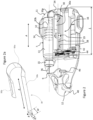
figures 1 to 3 , adrug delivery device 1 according to an embodiment of this invention includes adelivery system outlet 12 comprising a transcutaneous needle or a catheter tube for connection to a transcutaneous needle, aliquid reservoir 7 containing a medicament to be administered to a patient, a pumping system, and an electronic control and power supply system (not shown). The pumping system according to the invention comprises a piston pump 5 acting upon theliquid reservoir 7 and adosing unit 6 interconnecting theliquid reservoir 7 to thedelivery system outlet 12. - The drug delivery device according to an advantageous embodiment may comprise a multi-use
reusable portion 2 and a single-usedisposable portion 3 separable from the reusable part. - The drug delivery device according to an advantageous embodiment may be in the form of a patch pump device for mounting against the patient's skin with a transcutaneous needle fixed directly to the disposable parts and injectable through the patient's skin.
- The drug delivery device according to the invention however includes embodiments that are not in the form of patch units, for example in the form of a portable autonomous device that may be carried by the patient on a belt, in a pocket or bag, or placed on a table and connected for instance via a catheter to the patient. Embodiments may also include a drug delivery device for bolus administration of a medicament that is temporarily placed against a patient's skin at the time of administering the bolus dose and removed from the patient after or between administrations of a dose.
- In a patch unit embodiment of the drug delivery device, the
disposable part 2 may comprise a housing support with an adhesive base for bonding to the patient's skin. The electronic control and power supply systems (not shown) may advantageously be mounted in thereusable part 2. Further, adrive unit 11 comprising anelectrical motor 42 for driving a plunger actuator of the piston pump 5 may be mounted in thereusable part 3. The components mounted in the disposable part may include theliquid reservoir 7, thedosing unit 6, thedelivery system outlet 12 and the liquid flow channels fluidly interconnecting the aforesaid components. - In an embodiment, the
liquid reservoir 7 comprises acontainer wall 13, in particular a cylindrical container wall, hermetically sealed at one end by aplunger 14 that is sealingly and slideably movable within thecontainer wall 13 as liquid medicament contained within the liquid reservoir is expelled. The other end of thecontainer wall 13 may be provided with acap 15 comprising a septum arranged to be pierced by a hollow needle. In variants of the invention, instead of a cap with a septum, other fluidic connection systems such as a cap with a valve or other devices allowing liquid to flow out of the reservoir into a downstream liquid flow channel that are per se known may be provided. - In preferred embodiments, the
liquid reservoir 7 including theplunger 14 andcap 15 may be a standard vial of a drug manufacturer assembled in thereusable part 3 ordisposable part 2, or a custom reservoir integrated in thedisposable part 2 during manufacture of the disposable part. - The piston pump 5 comprises a plunger actuator arranged to push the
plunger 14 into thecontainer 13 thus applying pressure on the liquid contained within thereservoir 7. In the illustrated embodiment, the plunger actuator comprises alinear actuator 16 comprising ascrew 17 coupled to and driven in rotation by amotor 42 of thedrive unit 11, and anut 19 coupled to thescrew 17, thenut 19 being blocked in rotation by a housinglinear guide 38 but slidable in an axial direction A corresponding to the axis of rotation A of thescrew 17. - In the illustrated embodiment, the
screw 17 is advantageously arranged essentially parallel and laterally adjacent to a central axis of theliquid reservoir 7 as defined by the direction of displacement of theplunger 14. Anactuation rod 30 interconnects thenut 19 to apiston plate 32 pressing against theplunger 14. - In a preferred embodiment, the
actuation rod 30 is a bendable rod comprising abent section 30a forming a U shape betweenstraight sections 30b. - The parallel adjacent arrangement of the
linear actuator 16 andliquid reservoir 7 allows to provide a particularly compact piston pump and reservoir arrangement, in particular reducing the overall length L of the piston pump arrangement so that it may be conveniently mounted within a patch pump housing in a compact arrangement. - In an advantageous embodiment, the
bent actuation rod 30 may comprise a curved profile in an unbent state, when viewed in cross section orthogonal to the plunger displacement direction A. - The actuation rod may be made of a spring sheet metal beam configured to generate an essentially flattened profile in cross-section along a portion of the rod that is bent around a U shape as illustrated in
figure 2 . This configuration allows the actuation rod to be rigid in the direction of a buckling force aligned with thelinear sections 30b, yet flexible in a transverse direction to allow bending into the U shapedbent portion 30b such that a force may be transmitted by thenut 19 in the plunger displacement direction A to therod 30, the force being transmitted in the rod around the U-bend to thepiston plate 32. - The
bent portion 30a may be guided in ahousing guide slot 34 in a housing portion of the pumping system. - The housing portion forming the
housing guide slot 34 may advantageously be made of a low friction polymer such as Polytetrafluoroethylene (PTFE) to guide the flattened profilebent portion 30a of theactuation rod 30 as it slides in theslot 34 when thenut 19 is advanced or retracted by rotation of thescrew 17. - Other low friction guide mechanisms may be provided in variants, for instance comprising roller bearings mounted along the guide slot on a convex side of the
bent section 30a. - The
actuation rod 30 may advantageously be made of a tape of spring metal such as a stainless steel alloy. - In an advantageous embodiment of a drug delivery device, the tape of spring metal may have the following parameters:
- Tape metal thickness h between 40 and 60 micrometres (10-6 m)
- Width w between 5 and 12 mm
-
Bending height 6 between 0.5 and 2 mm - Radius R between 4 and 10 mm
- The
drive unit 11 may be actuated in a reverse direction to retract thenut 19 from the fully extended position P1 to the fully retracted position P2 to allow theliquid reservoir 7 anddisposable part 2 of the drug delivery device to be disconnected and separated from thereusable part 3 of the drug delivery device and for coupling a new disposable part to the reusable part. Once the disposable part has been coupled to the reusable part, thepiston plate 32 may be advanced until it abuts the rear end of theplunger 14 invention. - The
drive unit 11 may comprise anelectrical motor 42 connected to areduction gear system 44 driving thescrew 17 at a reduced rate of rotation speed compared to the rotor of the motor. The electrical motor may include a reduction system within the motor housing. The reduction gear system may also be formed of a first stage gearbox within the motor and a second stage gearbox outside of the motor, coupled to an output of the motor as illustrated infigure 2 for instance. Such linear actuators are per se known in the art and need not be described in further detail. It may be noted however that thelinear actuator 16 may comprise other configurations per se known in the field of linear actuators, connected to thebent actuation rod 30. - The
cap 15 of theliquid reservoir 7 is fluidly connected to thedosing unit 6. In the illustrated embodiment, the dosing unit comprises ahollow needle 36 that pierces through a septum of thecap 15. Thehollow needle 36 is connected to aliquid conduit 9 of thedosing unit 6. Theliquid conduit 9 comprises aninlet portion 18, anoutlet portion 20, and therebetween achamber portion 22. The dosing unit further comprises anactuation system 10 comprising aninlet valve 24 acting upon theinlet portion 18, anoutlet valve 26 acting upon theoutlet portion 20, and apump chamber actuator 28 acting upon thechamber portion 22 of the liquid conduit. - In an advantageous embodiment, the liquid conduit may be formed of a
flexible tube 9, for instance a tube made of a plastic material. - The dosing unit further comprises a base 29 on which the chamber portion is mounted. The
pump chamber actuator 28 may be configured to bias upon the chamber portion towards thebase 29, thereby pressing thechamber portion 22 against thebase 29. Thevalves base 29. - In an embodiment, the
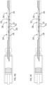
chamber portion 22 may comprise top andbottom walls figure 4b , and that separate apart as the chamber portion is filled with liquid, for instance as illustrated infigure 4d . The bottom wall may rest against abase 29 of the dosing unit. In an embodiment, the bottom wall may be bonded, for instance by welding or adhesive, to thebase 29. - In an embodiment the
bottom wall 31 may be bonded to the base 29 in an arrangement configured such that when liquid is injected into the chamber portion and thetop wall 33 moves away from thebottom wall 31, an elastic tensile stress is generated in thetop wall 33 of the chamber portion. This elastic tension in thetop wall 33 of thechamber portion 22 exerts a pressure on the liquid contained within the chamber portion. Thebottom wall 31 is this embodiment may be bonded to thebase 29 along its outer perimeter, or along portions of the outer perimeter, for instance along opposed lateral edges of the bottom wall. The bottom wall, in variants may also be bonded to the base 29 over essentially the whole surface of thebottom wall 31 or at discrete spots or portions distributed over the bottom wall. Any bonding configuration may be employed that serves the purpose of keeping the bottom wall bonded to the base as the top wall is being tensioned by the liquid filling thechamber portion 22. - The inlet valve, outlet valve and pump
chamber actuator - In an advantageous embodiment, in which the
liquid conduit 9 comprises a flexible tube, the inlet andoutlet valves - It may be noted however that within the scope of the invention other types of valves, per se known in the art of fluid flow systems, such as ball valves, butterfly valves, and disc check valves may be used to open and close the liquid channel.
- The
chamber portion 22 of theliquid conduit 9 in a fully expanded operational state contains a pump cycle volume of liquid that determines the volume of liquid medicament that may be pumped in each cycle of thedosing unit 6 as will be better described hereinafter. - The
chamber portion 22 comprises some elasticity in its expanded operational state, that allows the pump cycle volume to vary as a function of the inlet pressure that is generated by the upstream piston pump 5. - Referring now in particular to
figures 4a to 4h initial pumping steps of the pumping system will now be described. - Starting with
figure 4a , in an initial state when the drug delivery system comprises a new fullliquid reservoir 7, theplunger 14 is initially in an uncompressed state. - In a first step, as illustrated in
figure 4b (further consideringfigure 2 ), thedrive 11 is powered to displace thenut 19 andactuation rod 30 in a pumping direction such that thepiston plate 32 presses against an outer face of theplunger 14 pushing it into thereservoir container 13 and compressing the liquid contained therein. In this initial compression of the liquid in the reservoir, theinlet valve 24 is closed and prevents liquid flowing therethrough. In an embodiment comprising a pinch valve, the pinch valve actuator pinches theinlet section 18 of theflexible tube 9 such that the liquid channel inside the inlet section is closed. - The
inlet valve 24 is then opened as illustrated infigure 4c while theplunger 14 is being pressed into the reservoir by the plunger actuator. In an embodiment comprising a pinch valve, the pinch valve actuator biases away from theinlet section 18 of theflexible tube 9 such that the liquid channel inside the inlet section is opened. - Liquid is thus forced into the chamber portion as illustrated in
figure 4d , either by actively biasing thepump chamber actuator 28 away from the closed position to an expanded position, or by passively allowing thepump chamber actuator 28 to elastically bias away from the closed position to an expanded position due to the pressure of the liquid pumped by the upstream piston pump 5 into thechamber portion 22. In this regard, the pump chamber actuator may comprise an active electrical actuator, or may comprise a spring biased actuator that presses on thechamber portion 22 of the flexible tube. - The
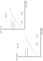
chamber portion 22 comprises some elasticity in its full state configured to allow thechamber portion 22 in its full state to expand elastically as a function of the pressure that is applied to the liquid. An example of the elastic expansion characteristic of the chamber portion in its full state is illustrated infigure 5a , whereby the dosage volume of one pump cycle at ambient pressure (at rest) is less than the dosage volume of one pump cycle at an operational (working) pressure greater than ambient pressure. - In the embodiment in which the
bottom wall 31 is bonded to the base 29 such that the top wall is already under tensile elastic stress when liquid starts being injected in the chamber portion, the elastic expansion characteristic of thechamber portion 22 may have a characteristic as illustrated infigure 5b or 5c. In this embodiment, the dosage volume of one pump cycle at a predefined target pressure that is greater than ambient pressure taking into account the compression provided by the wall of the chamber portion, is less or more than the dosage volume of one pump cycle at an operational (working) pressure that determines the dosage per cycle. In other words, the operational (working) pressure may be at a value above the predefined target pressure, or at a value below the predefined target pressure. - In an embodiment comprising a flexible tube forming the liquid conduit, the elasticity may in part or in whole be provided by the material of the flexible tube. In variants however, the elasticity may be provided in whole or in part by a spring biased actuator mounted against, or elastic sleeve mounted around, the
chamber portion 22. - As illustrated in
figure 4d , liquid goes into thechamber portion 22 and the volume contained therein depends on the pressure in thereservoir 7. In subsequent steps as illustrated infigures 4e followed byfigure 4f , theinlet valve 24 is closed and theoutlet valve 26 is opened to allow liquid to flow out through theoutlet section 20 of theliquid conduit 9 as illustrated infigure 4f thus fluidly connecting thechamber portion 22 to thedelivery outlet 12 of the drug delivery device. - Liquid is ejected from the
chamber portion 22, either by applying pressure on thepump chamber actuator 28 by means of an electrically driven actuator or by means of a passive spring biased element applying pressure on thepump chamber actuator 28 until the pump chamber is empty or essentially empty as illustrated infigure 4g . Theoutput valve 26 is then closed such that theoutlet section 20 of theliquid conduit 9 is closed and a new pump cycle may be started with the steps illustrated infigures 4b to 4h . - It may be noted that the order for carrying out the pumping cycles of the piston pump and the dosing unit can also be reversed or simultaneous. For instance, in a variant, a single motor may be used for actuating both simultaneously.
- After the initial pump cycle described above, there is a certain pressure in the
liquid reservoir 7 and theplunger 14 is in at least a partially compressed state. It may be noted however that during the first step of opening the inlet section and filling thepump chamber portion 22, due to the stick-slip effect on theelastic plunger 14 the degree of compression of the plunger may vary within a certain range that may lead to the pressure in the reservoir after the first cycle not being completely stabilized within an accurate pre-defined pressure range, for instance within a range of 30 % above or below a desired pressure. A second, third, fourth or more cycles of pumping going through the steps illustrated infigures 4b to 4h may be performed in order to ensure that theplunger 14 is compressed within a stabilized range of compression that is independent of the initial uncompressed state. It is also possible in a variant to operate dissimilar numbers of pumping cycles for the piston pump and the dosing unit depending on their respective calibrated pumping volumes. - The first or the first and subsequent second, third, fourth or more initial pumping cycles may constitute an initialization or priming operation for the drug delivery device prior to first use by the patient.
- In an embodiment, the initialization procedure may comprise the following steps :
- i. the
cartridge 7 is inserted and locked into thereusable part 3, whereby the outlet is not yet connected to thedisposable part 2, - ii. a series of pumping cycles are operated to build a minimal pressure in the
cartridge 7, - iii. the
disposable part 2 is assembled to thereusable part 3 and thus thecartridge 7 is now fluidically connected to the disposable part - iv. a few pumping cycles involving both the piston pump 5 and the
dosing unit 6 are done in order to fill the system up to theoutlet 12 of thedisposable part 2, - v. the drug delivery device may, according to a variant, be connected to an infusion set.
- In an exemplary embodiment, the pressure in the
reservoir 7 at the end of a priming operation may be stabilized, for instance in a range of between 200 and 300 millibars, for instance around 250 millibars. - In an advantageous embodiment, the dosing unit is configured such that a minimal number of 100 cycles must be performed for the dosing unit to empty the cartridge. The delivered volume of one cycle is linked to the smallest delivered volume of the drug delivery device.
- Advantageously, the overpressure in the
liquid reservoir 7 ensures that the pump system delivers accurate volumes of liquid at each cycle with a very low variation of volume from one cycle to the next because of the auto-calibration between thedosing unit 6 and the piston pump 5. - This auto calibration is a consequence of the elasticity of the chamber portion in its expanded operation state compared to the elasticity of the
plunger 14, whereby the volume variation of the chamber portion as a function of the pressure variation, is smaller than the volume variation in the liquid reservoir 7 (due to the elasticity of the plunger 14) for the same pressure variation. The dosing unit thus has acts a damping system on possible pressure variations of the liquid reservoir due to the variable position of the elastic plunger subject to a stick slip effect in it's displacement. - Another advantage of the overpressure within the
reservoir 7 is the reduction of formation of bubbles due to the increased vapour saturation temperature of the liquid at pressure. - For instance, in the case of insulin, the saturation temperature with 250 millibars of overpressure corresponds, at ambient temperatures, to an increase of about 15° Celsius.
- For the sake of completeness, the term "ambient pressure" is considered to be the air pressure in the environment of use of the medical device, which is around 1 bar, and "ambient temperature" is considered to be the ISO standard ambient temperature of 20°C.
- In one example for use with concentrated insulin, a volume of liquid injected per cycle corresponds for instance to about 0.5 microliters with 250 millibars pressure (over ambient pressure) delivered by the piston pump, whereas at ambient pressure, namely when the
dosing unit 6 functions as a micropump without overpressure at the inlet, the pump cycle volume is about 10 % lower, for instance around 0.45 microliters per pump cycle. This last value does not need to be very accurate which is of great advantage for economical high volume production. - In another example for use with concentrated insulin, a volume of liquid injected per cycle corresponds for instance to about 0.25 microliters with 650 millibars pressure (over ambient pressure) delivered by the piston pump, whereas at the target pressure of 750 millibars, the pump cycle volume is about 10 % higher, for instance around 0.275 microliters per pump cycle. This last value does not need to be very accurate which is of great advantage for economical high volume production.
- With the pressure provided by the piston pump 5 after the priming operation, the dosing unit achieves a stabilized (calibrated) volume of liquid delivered at each cycle that has a very low variation from one cycle to the next. The effects of the variable compression of the
plunger 14 due to its elastic properties and the stick-slip effect of friction between the plunger and the reservoir container wall are significantly reduced by thedosing unit 6 because of the stabilized overpressure in thereservoir 7 after each pumping cycle. The overall volume delivered by a plurality of cycles will however depend on the displacement of theplunger 14 by thelinear actuator 16 which is very accurate. Thus the drug delivery is accurate both over short and long term use. Moreover, the overpressure provided by the combination of the piston pump and dosing unit reduces the formation of bubbles in the liquid. - In the illustrated embodiments the dosing unit is essentially in the form of a peristaltic pumping unit, in particular a shuttle peristaltic pump however within the scope of the invention, the dosing unit can be in the form of various volumetric incremental pumps with the property that the delivered volume per cycle varies as a function of the inlet pressure. For instance the dosing unit may comprise a membrane type of pump, whereby the elastic membrane of the pump unit has the property that the delivered volume per cycle varies as a function of the inlet pressure. Other membrane, peristaltic or tube pumps with elastic properties may be implemented for the dosing unit.
-
Drug delivery device 1 -
reusable part 3-
drive unit 11-
electrical motor 42 -
reduction gear mechanism 44
-
- control system
-
-
disposable part 2-
delivery system outlet 12 - pumping system
- piston pump 5
-
liquid reservoir 7-
container wall 13 -
plunger 14 -
cap 15
liquid chamber portion
-
- plunger actuator
-
actuation rod 30-
bent portion 30a -
straight portion 30b
-
- housing guide slot 34 (in housing)
-
piston plate 32 -
linear actuator 16- screw 17
-
nut 19 - housing linear guide 38 (for nut)
-
-
-
dosing unit 6- peristaltic dosing unit
- connector or
needle 36 -
flexible tube 9-
inlet 18 -
outlet 20 -
chamber portion 22-
bottom wall 31 -
top wall 33
-
-
-
actuation system 10-
inlet valve 24
pinch valve actuator -
outlet valve 26
pinch valve actuator - pump chamber actuator(s) 28
-
-
base 29
- piston pump 5
-
Claims (15)
- A drug delivery device comprising a pumping system and a liquid reservoir (7) fluidly connected to a delivery system outlet (12), the liquid reservoir comprising an elastic plunger (14) sealingly slidable within a rigid container wall (13) of the liquid reservoir for expelling liquid out of the reservoir, the pumping system comprising a piston pump (5) comprising an electrically driven plunger actuator arranged to displace the plunger (14) a predefined distance per pump cycle, and a dosing unit (6) arranged downstream of the liquid reservoir (7) and fluidly connected to the liquid reservoir, the dosing unit (6) comprising a chamber portion (22) arranged between an inlet valve (24) and an outlet valve (26), the chamber portion (22) arranged to receive from the liquid reservoir a discrete pump cycle volume of liquid under an operational pressure generated by the piston pump greater than ambient pressure, and to deliver said pump cycle volume of liquid to the delivery system outlet, characterized by said discrete pump cycle volume being dependent on the operational pressure.
- Drug delivery device according to the preceding claim, wherein the operational pressure is in a range between 10 and 1600 millibars over ambient pressure, preferably in a range between 10 and 1000 millibars over ambient pressure, more preferably in a range between 500 and 1000 millibars over ambient pressure.
- Drug delivery device according to any preceding claim, wherein the chamber portion is elastically expandable at least in a state when filled with a pump cycle volume of liquid.
- Drug delivery device according to the preceding claim, wherein an elastic property of the elastic expandable chamber portion defined by a volume change ΔV multiplied by an operational pressure greater than ambient pressure ΔP is in a range of :


- Drug delivery device according to any of the preceding claims, wherein the dosing unit comprises a flexible tube (9) incorporating the chamber portion (22).
- Drug delivery device according to any of the preceding claims, wherein the chamber portion comprises top and bottom walls (33, 31) that lie against each other when the chamber portion is empty, and that separate apart as the chamber portion is filled with liquid, the bottom wall resting against a base (29) of the dosing unit.
- Drug delivery device according to the preceding claim, wherein the bottom wall is bonded to the base (29), the bonding arranged along at least portions of a perimeter of the bottom wall such that when liquid is injected into the chamber portion and the top wall (33) moves away from the bottom wall (31), an elastic tensile stress is generated in the top wall (33) of the chamber portion.
- Drug delivery device according to any preceding claim, wherein the inlet and outlet valves are in the form of pinch valves.
- Drug delivery device according to any of the preceding claims, comprising a pump chamber actuator (28) arranged to bias against the chamber portion (22) to expel liquid out of the chamber portion to deliver said pump cycle volume of liquid to the delivery system outlet.
- Drug delivery device according to any preceding claim, wherein the plunger actuator comprises a linear actuator (16) and a bent actuation rod (30) coupled at a first end to the linear actuator and at a second end to the plunger (14), the linear actuator being arranged parallel and laterally adjacent to the liquid reservoir (7).
- Drug delivery device according to the preceding claim, wherein the linear actuator comprises a linear screw (17) and a nut (19) blocked in rotation and slideably movable upon rotation of the screw.
- Drug delivery device according to either of the two directly preceding claims, wherein the actuation rod (30) comprises a curved spring sheet beam, the actuation rod (30) having a portion (30a) bent in a U-shape between straight sections (30b).
- Drug delivery device according to the preceding claim, wherein the U-Shape bent portion (30a) of the actuation rod is slidably guided in a housing guide slot (34) of the housing.
- Drug delivery device according to any preceding claim, wherein the actuation rod (30) is made of a tape of spring metal.
- Drug delivery device according to any of the preceding claims, wherein the liquid reservoir (7), dosing unit (6), and drug outlet (12) form part of a disposable part (2) of the drug delivery device connectable and separable from a reusable part (3) of the drug delivery device, the reusable part comprising the plunger actuator, a control system for controlling the pump system (4), and an electrical drive unit (11) coupled to the plunger actuator.
Applications Claiming Priority (3)
| Application Number | Priority Date | Filing Date | Title |
|---|---|---|---|
| EP17206304 | 2017-12-08 | ||
| EP18157285 | 2018-02-16 | ||
| PCT/EP2018/084069 WO2019110839A1 (en) | 2017-12-08 | 2018-12-08 | Drug delivery device |
Publications (3)
| Publication Number | Publication Date |
|---|---|
| EP3720522A1 EP3720522A1 (en) | 2020-10-14 |
| EP3720522B1 true EP3720522B1 (en) | 2023-06-07 |
| EP3720522C0 EP3720522C0 (en) | 2023-06-07 |
Family
ID=64664752
Family Applications (1)
| Application Number | Title | Priority Date | Filing Date |
|---|---|---|---|
| EP18819061.5A Active EP3720522B1 (en) | 2017-12-08 | 2018-12-08 | Drug delivery device |
Country Status (4)
| Country | Link |
|---|---|
| US (3) | US11529458B2 (en) |
| EP (1) | EP3720522B1 (en) |
| CN (1) | CN111432860B (en) |
| WO (1) | WO2019110839A1 (en) |
Families Citing this family (11)
| Publication number | Priority date | Publication date | Assignee | Title |
|---|---|---|---|---|
| IL276435B (en) | 2015-03-10 | 2022-08-01 | Regeneron Pharma | Aseptic piercing system and method |
| PL3377146T3 (en) | 2015-11-20 | 2021-10-11 | Amf Medical Sa | Micropump and method of manufacturing a micropump |
| AU2018260992B9 (en) | 2017-05-05 | 2024-02-15 | Regeneron Pharmaceuticals, Inc. | Auto-injector |
| CN111432860B (en) * | 2017-12-08 | 2023-08-08 | 坦德姆糖尿病护理瑞士有限责任公司 | Drug delivery device |
| WO2022067003A1 (en) * | 2020-09-25 | 2022-03-31 | Xiaodong Wu | Apparatus and methods for treating disease or disorder |
| US11241530B1 (en) | 2020-11-23 | 2022-02-08 | Amf Medical Sa | Insulin patch pump having photoplethysmography module |
| US11857757B2 (en) | 2021-06-01 | 2024-01-02 | Tandem Diabetes Care Switzerland Sàrl | Systems and methods for delivering microdoses of medication |
| US11679199B2 (en) | 2021-06-01 | 2023-06-20 | Amf Medical Sa | Systems and methods for delivering microdoses of medication |
| WO2022254286A1 (en) | 2021-06-01 | 2022-12-08 | Amf Medical Sa | Systems and methods for delivering microdoses of medication |
| US11541169B2 (en) | 2021-06-01 | 2023-01-03 | Amf Medical Sa | Applicators for systems and methods for delivering microdoses of medication |
| EP4626513A1 (en) | 2022-11-30 | 2025-10-08 | Tandem Diabetes Care Switzerland Sàrl | Devices for inserting transcutaneous cannulas for patch pumps |
Family Cites Families (189)
| Publication number | Priority date | Publication date | Assignee | Title |
|---|---|---|---|---|
| US2105200A (en) | 1934-04-25 | 1938-01-11 | Hugh G Phelps | Surgical pump |
| US2412397A (en) | 1943-12-31 | 1946-12-10 | Lyndus E Harper | Flexible tube pump |
| CH505294A (en) | 1969-03-21 | 1971-03-31 | Polymetron Ag | Peristaltic pump |
| US4042153A (en) | 1973-03-14 | 1977-08-16 | Standard Oil Company | Liquid dropping device |
| US4199307A (en) | 1977-07-05 | 1980-04-22 | Andros Incorporated | Medical infusion system |
| US4273121A (en) | 1978-02-17 | 1981-06-16 | Andros Incorporated | Medical infusion system |
| US4218416A (en) | 1978-11-13 | 1980-08-19 | Baxter Travenol Laboratories, Inc. | Method for extruding a parison |
| US4236880A (en) | 1979-03-09 | 1980-12-02 | Archibald Development Labs, Inc. | Nonpulsating IV pump and disposable pump chamber |
| US4410322A (en) | 1979-03-09 | 1983-10-18 | Avi, Inc. | Nonpulsating TV pump and disposable pump chamber |
| US4322201A (en) | 1979-03-09 | 1982-03-30 | Avi, Inc. | IV Pump with back pressure control |
| US4290346A (en) | 1979-04-30 | 1981-09-22 | Abbott Laboratories | Intravenous pump chamber |
| US4482347A (en) | 1982-08-12 | 1984-11-13 | American Hospital Supply Corporation | Peristaltic fluid-pumping apparatus |
| US4493704A (en) * | 1982-11-29 | 1985-01-15 | Oximetrix, Inc. | Portable fluid infusion apparatus |
| US4501405A (en) | 1983-06-21 | 1985-02-26 | Bunnell Life Systems, Inc. | Frictionless valve/pump |
| IL69431A (en) | 1983-08-04 | 1987-12-31 | Omikron Scient Ltd | Liquid delivery system particularly useful as an implantable micro-pump for delivering insulin or other drugs |
| US4616802A (en) * | 1984-12-06 | 1986-10-14 | Baxter Travenol Laboratories, Inc. | Tubing occluder |
| US4657490A (en) | 1985-03-27 | 1987-04-14 | Quest Medical, Inc. | Infusion pump with disposable cassette |
| US4934372A (en) | 1985-04-01 | 1990-06-19 | Nellcor Incorporated | Method and apparatus for detecting optical pulses |
| US4617014A (en) | 1985-11-26 | 1986-10-14 | Warner-Lambert Company | Dual mode I. V. infusion device |
| US4854836A (en) | 1986-02-18 | 1989-08-08 | Baxter International Inc. | Collapsible conduit for linear peristaltic pump and method of making the same |
| US5056992A (en) | 1987-05-29 | 1991-10-15 | Hewlett-Packard Company | IV pump and disposable flow chamber with flow control |
| DE3909657A1 (en) | 1989-03-23 | 1990-09-27 | Braun Melsungen Ag | PUMP HOSE FOR A PERISTALTIC PUMP |
| US5137023A (en) | 1990-04-19 | 1992-08-11 | Worcester Polytechnic Institute | Method and apparatus for monitoring blood analytes noninvasively by pulsatile photoplethysmography |
| EP0412191B1 (en) | 1989-08-09 | 1993-02-03 | Siemens Aktiengesellschaft | Implantable infusion device |
| US5217355A (en) | 1991-08-05 | 1993-06-08 | Imed Corporation | Two-cycle peristaltic pump with occlusion detector |
| US5318546A (en) * | 1992-08-28 | 1994-06-07 | Bierman Steven F | Method of catheter irrigation and aspiration |
| US5252044A (en) | 1992-10-20 | 1993-10-12 | Medflow, Inc. | Parenteral fluid pump with disposable cassette |
| DK109293D0 (en) * | 1993-09-27 | 1993-09-27 | Novo Nordisk As | APPARATUS |
| US5482446A (en) | 1994-03-09 | 1996-01-09 | Baxter International Inc. | Ambulatory infusion pump |
| US5637095A (en) * | 1995-01-13 | 1997-06-10 | Minimed Inc. | Medication infusion pump with flexible drive plunger |
| US5853364A (en) | 1995-08-07 | 1998-12-29 | Nellcor Puritan Bennett, Inc. | Method and apparatus for estimating physiological parameters using model-based adaptive filtering |
| US6165151A (en) | 1996-09-03 | 2000-12-26 | Weiner; Daniel L. | Apparatus and methods for control of intravenous sedation |
| US6093172A (en) | 1997-02-05 | 2000-07-25 | Minimed Inc. | Injector for a subcutaneous insertion set |
| US7329239B2 (en) | 1997-02-05 | 2008-02-12 | Medtronic Minimed, Inc. | Insertion device for an insertion set and method of using the same |
| US5851197A (en) | 1997-02-05 | 1998-12-22 | Minimed Inc. | Injector for a subcutaneous infusion set |
| US6607509B2 (en) | 1997-12-31 | 2003-08-19 | Medtronic Minimed, Inc. | Insertion device for an insertion set and method of using the same |
| US5964583A (en) | 1997-10-15 | 1999-10-12 | Baxter International Inc. | Elastomerically assisted peristaltic pump |
| JP4647098B2 (en) | 1997-12-31 | 2011-03-09 | メドトロニック ミニメド インコーポレイテッド | Insertion device for insertion set |
| US6800071B1 (en) * | 1998-10-29 | 2004-10-05 | Medtronic Minimed, Inc. | Fluid reservoir piston |
| US20050277887A1 (en) * | 2000-05-08 | 2005-12-15 | Joel Douglas | Micro infusion drug delivery device |
| JP2002021743A (en) | 2000-07-03 | 2002-01-23 | Yutaka Doi | Tube pump |
| DK1335764T3 (en) | 2000-09-08 | 2007-10-01 | Insulet Corp | Patient infusion apparatus and system |
| US6537251B2 (en) | 2000-10-05 | 2003-03-25 | Novo Nordisk A/S | Medication delivery device with bended piston rod |
| IL141137A0 (en) | 2001-01-28 | 2002-02-10 | Caesaria Med Electronics Ltd | Liquid pump |
| US6749587B2 (en) * | 2001-02-22 | 2004-06-15 | Insulet Corporation | Modular infusion device and method |
| DK3210637T3 (en) | 2001-04-06 | 2021-04-06 | Hoffmann La Roche | Infusion set |
| US20020071225A1 (en) | 2001-04-19 | 2002-06-13 | Minimed Inc. | Direct current motor safety circuits for fluid delivery systems |
| US6830562B2 (en) | 2001-09-27 | 2004-12-14 | Unomedical A/S | Injector device for placing a subcutaneous infusion set |
| US6723077B2 (en) | 2001-09-28 | 2004-04-20 | Hewlett-Packard Development Company, L.P. | Cutaneous administration system |
| US7204823B2 (en) | 2001-12-19 | 2007-04-17 | Medtronic Minimed, Inc. | Medication delivery system and monitor |
| US20080172026A1 (en) | 2006-10-17 | 2008-07-17 | Blomquist Michael L | Insulin pump having a suspension bolus |
| US7144384B2 (en) | 2002-09-30 | 2006-12-05 | Insulet Corporation | Dispenser components and methods for patient infusion device |
| CN1496744A (en) * | 2002-10-18 | 2004-05-19 | 尼普洛株式会社 | Soup syringe |
| JP2004135907A (en) | 2002-10-18 | 2004-05-13 | Nipro Corp | Chemical injection device |
| DE10337484B4 (en) | 2003-08-14 | 2005-05-25 | Zengerle, Roland, Prof. Dr. | Microdosing device and method for the metered dispensing of liquids |
| US7699807B2 (en) | 2003-11-10 | 2010-04-20 | Smiths Medical Asd, Inc. | Device and method for insertion of a cannula of an infusion device |
| US7356364B1 (en) | 2004-01-23 | 2008-04-08 | University Of Hawai'i | Device for optical monitoring of constituent in tissue or body fluid sample using wavelength modulation spectroscopy, such as for blood glucose levels |
| US8337482B2 (en) | 2004-04-19 | 2012-12-25 | The Invention Science Fund I, Llc | System for perfusion management |
| US8062250B2 (en) | 2004-08-10 | 2011-11-22 | Unomedical A/S | Cannula device |
| WO2006108304A1 (en) | 2005-04-11 | 2006-10-19 | Disetronic Licensing Ag | Web-enabled portable medical device |
| EP1722310A1 (en) | 2005-04-12 | 2006-11-15 | Roche Diagnostics GmbH | Medical software download to mobile phone |
| EP1716879B1 (en) * | 2005-04-25 | 2008-11-05 | F. Hoffmann-La Roche AG | Infusion device with watertight enclosure |
| US8512288B2 (en) * | 2006-08-23 | 2013-08-20 | Medtronic Minimed, Inc. | Infusion medium delivery device and method with drive device for driving plunger in reservoir |
| US7686787B2 (en) | 2005-05-06 | 2010-03-30 | Medtronic Minimed, Inc. | Infusion device and method with disposable portion |
| US20070060874A1 (en) | 2005-09-12 | 2007-03-15 | Nesbitt Matthew T | Apparatus and methods for controlling and automating fluid infusion activities |
| BRPI0707576A2 (en) | 2006-02-09 | 2011-05-10 | Deka Products Limited Partnership | pumping fluid delivery systems and force application assembly methods of use |
| EP1818664B1 (en) | 2006-02-13 | 2013-05-01 | F.Hoffmann-La Roche Ag | Device for detection of a change of pressure in a canal of a microdosing device |
| US20070191773A1 (en) | 2006-02-16 | 2007-08-16 | Animas Corporation | Low profile infusion set |
| US20070191772A1 (en) | 2006-02-16 | 2007-08-16 | Animas Corporation | Straight insertion safety infusion set |
| US7682338B2 (en) * | 2006-08-23 | 2010-03-23 | Medtronic Minimed, Inc. | Infusion medium delivery system, device and method with needle inserter and needle inserter device and method |
| US9056165B2 (en) | 2006-09-06 | 2015-06-16 | Medtronic Minimed, Inc. | Intelligent therapy recommendation algorithm and method of using the same |
| EP1944150B1 (en) | 2007-01-11 | 2013-03-27 | Ems-Chemie Ag | Suction blow moulding tool for manufacturing extruded plastic vacuum and blow moulded parts, manufacturing method and the use |
| EP1961436B1 (en) | 2007-02-24 | 2016-08-24 | Roche Diabetes Care GmbH | Infusion system |
| DK1983456T3 (en) | 2007-04-19 | 2013-11-25 | Hoffmann La Roche | Method of setting a basal rate profile for an insulin pump |
| EP2152148A2 (en) | 2007-05-07 | 2010-02-17 | Medingo Ltd. | Reciprocating delivery of fluids to the body with analyte concentration monitoring |
| US8221345B2 (en) | 2007-05-30 | 2012-07-17 | Smiths Medical Asd, Inc. | Insulin pump based expert system |
| EP2155296B1 (en) | 2007-06-20 | 2019-08-28 | Unomedical A/S | Cannula insertion device with automatic needle retraction comprising only one spring |
| US8002752B2 (en) | 2007-06-25 | 2011-08-23 | Medingo, Ltd. | Protector apparatus |
| WO2009001350A1 (en) | 2007-06-27 | 2008-12-31 | Medingo Ltd. | Tubing for fluid delivery device |
| PT2173410E (en) | 2007-07-10 | 2011-05-05 | Unomedical As | Inserter having two springs |
| US7879026B2 (en) | 2007-09-07 | 2011-02-01 | Asante Solutions, Inc. | Controlled adjustment of medicine dispensation from an infusion pump device |
| US8303545B2 (en) | 2007-09-07 | 2012-11-06 | Stat Medical Devices, Inc. | Infusion device and method of using and making the same |
| US8048040B2 (en) | 2007-09-13 | 2011-11-01 | Masimo Corporation | Fluid titration system |
| US20090177142A1 (en) | 2008-01-09 | 2009-07-09 | Smiths Medical Md, Inc | Insulin pump with add-on modules |
| US8845613B2 (en) | 2008-01-28 | 2014-09-30 | Roche Diagnostics Operations, Inc. | Bolus dose determination for a therapeutic fluid dispensing system |
| DK2252956T3 (en) | 2008-03-03 | 2019-03-25 | Hoffmann La Roche | INSULIN PUMP WITH REPLACEMENT OPPORTUNITIES |
| EP2141620B1 (en) | 2008-07-01 | 2018-10-31 | Roche Diabetes Care GmbH | Insulin pump and method for controlling a user interface of an insulin pump |
| US8140275B2 (en) | 2008-07-18 | 2012-03-20 | Insulet Corporation | Calculating insulin on board for extended bolus being delivered by an insulin delivery device |
| EP2164013B1 (en) | 2008-09-02 | 2017-03-01 | F. Hoffmann-La Roche AG | Method and apparatus for setting a basal rate profile for an insulin pump |
| WO2010026570A2 (en) | 2008-09-02 | 2010-03-11 | Medingo Ltd. | Remote control for fluid dispensing device with a echargeable power source |
| US8156070B2 (en) | 2008-09-05 | 2012-04-10 | Roche Diagnostics Operations, Inc. | Insulin pump programming software with basal profile preview feature |
| US8231562B2 (en) | 2008-09-05 | 2012-07-31 | Roche Diagnostics Operations, Inc. | Insulin pump configuration programming invalid settings notification and correction |
| US8452953B2 (en) | 2008-09-05 | 2013-05-28 | Roche Diagnostics Operations, Inc. | Insulin pump programming software for selectively modifying configuration data |
| US8105269B2 (en) | 2008-10-24 | 2012-01-31 | Baxter International Inc. | In situ tubing measurements for infusion pumps |
| WO2010150257A2 (en) | 2009-06-25 | 2010-12-29 | Medingo Ltd. | A method and device for improving glycemic control based on residual insulin |
| DK2453950T3 (en) * | 2009-07-13 | 2017-01-16 | Nestec Sa | Infusion pump with infusion cartridges |
| CA2769030C (en) * | 2009-07-30 | 2016-05-10 | Tandem Diabetes Care, Inc. | Infusion pump system with disposable cartridge having pressure venting and pressure feedback |
| US20110137297A1 (en) | 2009-09-17 | 2011-06-09 | Kiani Massi Joe E | Pharmacological management system |
| WO2011051940A1 (en) | 2009-10-30 | 2011-05-05 | Medingo Ltd. | Systems, methods and devices for adjusting the insertion depth of a cannula associated with a portable therapeutic device |
| US8092428B2 (en) | 2009-12-23 | 2012-01-10 | Roche Diagnostics Operations, Inc. | Methods and systems for adjusting an insulin delivery profile of an insulin pump |
| KR101142430B1 (en) | 2010-01-20 | 2012-05-08 | 포항공과대학교 산학협력단 | Micro pump and driving method thereof |
| US8377002B2 (en) | 2010-03-24 | 2013-02-19 | Medtronic Minimed, Inc. | Connection and alignment systems and methods |
| DK2436414T3 (en) * | 2010-05-18 | 2015-04-13 | Ivax Pharmaceuticals Ireland | Dose Counter to inhalers and inhaler |
| CA2808379C (en) | 2010-08-17 | 2019-04-09 | University Of Florida Research Foundation, Inc. | Central site photoplethysmography, medication administration, and safety |
| US9750875B2 (en) | 2010-09-24 | 2017-09-05 | Perqflo, Llc | Infusion pumps |
| US9498573B2 (en) | 2010-09-24 | 2016-11-22 | Perqflo, Llc | Infusion pumps |
| EP2436412A1 (en) | 2010-10-04 | 2012-04-04 | Unomedical A/S | A sprinkler cannula |
| US8861731B2 (en) | 2010-10-15 | 2014-10-14 | Roche Diagnostics Operations, Inc. | Efficient procedure for pairing medical devices for wireless communication with limited user interaction |
| US8454554B2 (en) | 2010-10-15 | 2013-06-04 | Roche Diagnostics Operations, Inc. | Use of a handheld medical device as a communications mediator between a personal computer-based configurator and another networked medical device |
| US8401194B2 (en) | 2010-10-15 | 2013-03-19 | Roche Diagnostics Operations, Inc. | Diabetes care kit that is preconfigured to establish a secure bidirectional communication link between a blood glucose meter and insulin pump |
| US8905972B2 (en) | 2010-11-20 | 2014-12-09 | Perqflo, Llc | Infusion pumps |
| US8586687B2 (en) | 2010-12-17 | 2013-11-19 | Nippon Shokubai Co., Ltd. | Polyalkylene glycol-based polymer and process for producing the same |
| US10251583B2 (en) | 2010-12-22 | 2019-04-09 | Roche Diabetes Care, Inc. | Insulin pump and methods for operating the insulin pump |
| EP2495001A1 (en) | 2011-03-03 | 2012-09-05 | Debiotech S.A. | Cannula inserter |
| WO2012131044A1 (en) | 2011-03-30 | 2012-10-04 | Unomedical A/S | Subcutaneous inserter device |
| US9642568B2 (en) | 2011-09-06 | 2017-05-09 | Medtronic Minimed, Inc. | Orthogonally redundant sensor systems and methods |
| GB201117539D0 (en) | 2011-10-11 | 2011-11-23 | Univ Graz Med | Medical apparatus having infusion and detection capabilities |
| PL4201327T3 (en) | 2012-03-30 | 2024-11-04 | Insulet Corporation | Fluid delivery device with transcutaneous access tool, insertion mechanism and blood glucose monitoring for use therewith |
| US9615779B2 (en) | 2012-04-04 | 2017-04-11 | Dexcom, Inc. | Transcutaneous analyte sensors, applicators therefor, and associated methods |
| US9005129B2 (en) | 2012-06-22 | 2015-04-14 | Fitbit, Inc. | Wearable heart rate monitor |
| US9867929B2 (en) * | 2012-08-15 | 2018-01-16 | Becton, Dickinson And Company | Pump engine with metering system for dispensing liquid medication |
| US8808269B2 (en) | 2012-08-21 | 2014-08-19 | Medtronic Minimed, Inc. | Reservoir plunger position monitoring and medical device incorporating same |
| JP6205701B2 (en) | 2012-10-22 | 2017-10-04 | セイコーエプソン株式会社 | Fluid injection device |
| NZ709302A (en) | 2012-12-21 | 2018-11-30 | Deka Products Lp | System, method, and apparatus for electronic patient care |
| US9446186B2 (en) * | 2013-03-01 | 2016-09-20 | Bigfoot Biomedical, Inc. | Operating an infusion pump system |
| US10357606B2 (en) | 2013-03-13 | 2019-07-23 | Tandem Diabetes Care, Inc. | System and method for integration of insulin pumps and continuous glucose monitoring |
| US10201656B2 (en) | 2013-03-13 | 2019-02-12 | Tandem Diabetes Care, Inc. | Simplified insulin pump for type II diabetics |
| US9492608B2 (en) | 2013-03-15 | 2016-11-15 | Tandem Diabetes Care, Inc. | Method and device utilizing insulin delivery protocols |
| US9867953B2 (en) | 2013-06-21 | 2018-01-16 | Tandem Diabetes Care, Inc. | System and method for infusion set dislodgement detection |
| US9867937B2 (en) | 2013-09-06 | 2018-01-16 | Tandem Diabetes Care, Inc. | System and method for mitigating risk in automated medicament dosing |
| US9077693B2 (en) | 2013-09-23 | 2015-07-07 | Netflix, Inc. | Securely connecting control device to target device |
| EP2862586B1 (en) | 2013-10-21 | 2021-09-01 | F. Hoffmann-La Roche AG | Control unit for infusion pump units, including a controlled intervention unit |
| DE102013111800A1 (en) * | 2013-10-25 | 2015-04-30 | Dominik Niedenzu | Precision metering device with expandable volume chamber |
| WO2015070914A1 (en) | 2013-11-14 | 2015-05-21 | Hahn-Schickard-Gesellschaft Fuer Angewandte Forschung E.V. | Access device |
| US9735502B2 (en) | 2013-12-13 | 2017-08-15 | Hewlett Packard Enterprise Development Lp | Connector with a retainer assembly |
| EP3086828B1 (en) | 2013-12-26 | 2023-08-09 | Tandem Diabetes Care, Inc. | Integration of infusion pump with remote electronic device |
| US10232111B2 (en) | 2013-12-31 | 2019-03-19 | Abbvie Inc. | Pump, motor and assembly for beneficial agent delivery |
| US20150182688A1 (en) | 2013-12-31 | 2015-07-02 | Abbvie Inc. | Devices and methods for delivering a beneficial agent to a user |
| GB2523989B (en) | 2014-01-30 | 2020-07-29 | Insulet Netherlands B V | Therapeutic product delivery system and method of pairing |
| JP6166484B2 (en) | 2014-02-05 | 2017-07-19 | アップル インコーポレイテッド | Unified communication protocol for communication between controller and accessories |
| US9610402B2 (en) | 2014-03-24 | 2017-04-04 | Medtronic Minimed, Inc. | Transcutaneous conduit insertion mechanism with a living hinge for use with a fluid infusion patch pump device |
| US10279106B1 (en) | 2014-05-08 | 2019-05-07 | Tandem Diabetes Care, Inc. | Insulin patch pump |
| WO2015172962A1 (en) | 2014-05-14 | 2015-11-19 | Meamedical Ag | Metering device for dispensing pharmaceutical fluid from a reservoir having a spindle rod for displacement of the piston |
| US9669160B2 (en) | 2014-07-30 | 2017-06-06 | Tandem Diabetes Care, Inc. | Temporary suspension for closed-loop medicament therapy |
| DK3193982T3 (en) | 2014-09-15 | 2021-06-14 | Sanofi Sa | SKINPORTABLE MEDICINE INJECTION DEVICE WITH RELEASE SENSOR |
| US9459201B2 (en) | 2014-09-29 | 2016-10-04 | Zyomed Corp. | Systems and methods for noninvasive blood glucose and other analyte detection and measurement using collision computing |
| US9592335B2 (en) | 2014-10-20 | 2017-03-14 | Medtronic Minimed, Inc. | Insulin pump data acquisition device |
| US11896803B2 (en) | 2014-12-22 | 2024-02-13 | Medicus Engineering Aps | Electrocardiogram (ECG) electrodes having bio-potential electrodes |
| US9680646B2 (en) | 2015-02-05 | 2017-06-13 | Apple Inc. | Relay service for communication between controllers and accessories |
| US9942091B2 (en) | 2015-02-27 | 2018-04-10 | Roche Diabetes Care, Inc. | Pump configuration software wizard for configuring parameters of a handheld insulin pump |
| JP2016198411A (en) | 2015-04-14 | 2016-12-01 | セイコーエプソン株式会社 | Indwelling needle and liquid injection apparatus |
| WO2016187286A1 (en) | 2015-05-18 | 2016-11-24 | Tandem Diabetes Care, Inc. | Patch pump cartridge attachment |
| US9999721B2 (en) | 2015-05-26 | 2018-06-19 | Medtronic Minimed, Inc. | Error handling in infusion devices with distributed motor control and related operating methods |
| WO2017007660A1 (en) * | 2015-07-03 | 2017-01-12 | Merit Medical Systems, Inc. | Devices and methods for fluid infusion, drainage and collection |
| US9636457B2 (en) | 2015-07-19 | 2017-05-02 | Sanmina Corporation | System and method for a drug delivery and biosensor patch |
| WO2017053572A1 (en) | 2015-09-22 | 2017-03-30 | Thomas Jefferson University | Continuous subcutaneous insulin infusion catheter |
| LT3364861T (en) | 2015-10-21 | 2022-04-25 | Dexcom, Inc. | Transcutaneous analyte sensors, applicators therefor, and associated methods |
| PL3377146T3 (en) | 2015-11-20 | 2021-10-11 | Amf Medical Sa | Micropump and method of manufacturing a micropump |
| US10716896B2 (en) | 2015-11-24 | 2020-07-21 | Insulet Corporation | Wearable automated medication delivery system |
| EP4356821A1 (en) | 2015-12-30 | 2024-04-24 | DexCom, Inc. | Transcutaneous analyte sensor systems and methods |
| US9980140B1 (en) | 2016-02-11 | 2018-05-22 | Bigfoot Biomedical, Inc. | Secure communication architecture for medical devices |
| CA2958010C (en) | 2016-02-19 | 2021-09-07 | Covidien Lp | System and methods for video-based monitoring of vital signs |
| US10363374B2 (en) | 2016-05-26 | 2019-07-30 | Insulet Corporation | Multi-dose drug delivery device |
| WO2017220681A1 (en) | 2016-06-22 | 2017-12-28 | Roche Diabetes Care Gmbh | Medical device for transcutaneously inserting an insertable element into a body tissue |
| JP6998897B2 (en) | 2016-07-05 | 2022-01-18 | エフ ホフマン-ラ ロッシュ アクチェン ゲゼルシャフト | Injection device drive unit with block device |
| US9735893B1 (en) | 2016-07-21 | 2017-08-15 | Intel Corporation | Patch system for in-situ therapeutic treatment |
| WO2018024625A1 (en) | 2016-08-02 | 2018-02-08 | Sanofi-Aventis Deutschland Gmbh | Medicament delivery device |
| CN110249389A (en) | 2016-08-26 | 2019-09-17 | 塞奎阿纳医疗股份公司 | System and method for managing and analyzing data generated by implantable devices |
| JP6979060B2 (en) | 2016-09-02 | 2021-12-08 | エフ ホフマン−ラ ロッシュ アクチェン ゲゼルシャフト | Identification of fluid drug cartridge type |
| US10518069B2 (en) | 2016-10-28 | 2019-12-31 | Integra LifeSciences Switzerland Sarl | Implantable valve assembly with extended lifespan |
| KR102619150B1 (en) | 2017-03-09 | 2023-12-27 | 암겐 인코포레이티드 | Insertion mechanism for drug delivery device |
| EP3600493A4 (en) | 2017-03-31 | 2020-08-19 | Capillary Biomedical, Inc. | Helical insertion infusion device |
| JP7105800B2 (en) | 2017-04-20 | 2022-07-25 | ベクトン・ディキンソン・アンド・カンパニー | Infusion set with leak indicator |
| CN110678220B (en) | 2017-05-08 | 2022-06-28 | 美敦力泌力美公司 | Flexible Tubing, Cannulas and Insertion Needles |
| US11040137B2 (en) | 2017-05-19 | 2021-06-22 | Min Wei | Wearable drug delivery device |
| WO2019060839A1 (en) | 2017-09-25 | 2019-03-28 | Insulet Corporation | Pre-filled cartridge-based drug delivery device |
| US11147931B2 (en) | 2017-11-17 | 2021-10-19 | Insulet Corporation | Drug delivery device with air and backflow elimination |
| CN111432860B (en) | 2017-12-08 | 2023-08-08 | 坦德姆糖尿病护理瑞士有限责任公司 | Drug delivery device |
| US11160910B2 (en) | 2017-12-18 | 2021-11-02 | Alcon Inc. | Cassette annunciation |
| US11278668B2 (en) | 2017-12-22 | 2022-03-22 | Glysens Incorporated | Analyte sensor and medicant delivery data evaluation and error reduction apparatus and methods |
| DK179818B1 (en) | 2018-01-30 | 2019-07-08 | Subcuject Aps | VALVE FOR AN INJECTION AND INJECTION WITH SUCH VALVE |
| EP3591662A1 (en) | 2018-07-05 | 2020-01-08 | Advanced Microfluidics SA | Medical device and secure control system |
| US11241532B2 (en) | 2018-08-29 | 2022-02-08 | Insulet Corporation | Drug delivery system with sensor having optimized communication and infusion site |
| CN110947051B (en) | 2018-09-27 | 2022-03-01 | 捷普科技(上海)有限公司 | Injection device |
| US10736037B2 (en) | 2018-12-26 | 2020-08-04 | Tandem Diabetes Care, Inc. | Methods of wireless communication in an infusion pump system |
| US11642459B2 (en) | 2020-01-15 | 2023-05-09 | Becton, Dickinson And Company | System and method for air removal |
| WO2022047199A1 (en) | 2020-08-28 | 2022-03-03 | Capillary Biomedical, Inc. | Insulin infusion set |
| US11139754B1 (en) | 2020-10-09 | 2021-10-05 | Solax Power Network Technology (Zhejiang) Co., Ltd. | Inverter circuit for realizing high-efficiency control of single-phase power of single-phase three-wire power supply |
| US11241530B1 (en) | 2020-11-23 | 2022-02-08 | Amf Medical Sa | Insulin patch pump having photoplethysmography module |
-
2018
- 2018-12-08 CN CN201880078668.4A patent/CN111432860B/en active Active
- 2018-12-08 EP EP18819061.5A patent/EP3720522B1/en active Active
- 2018-12-08 WO PCT/EP2018/084069 patent/WO2019110839A1/en not_active Ceased
- 2018-12-08 US US16/769,566 patent/US11529458B2/en active Active
-
2022
- 2022-12-19 US US18/068,255 patent/US11813428B2/en active Active
-
2023
- 2023-11-10 US US18/506,136 patent/US20240100248A1/en active Pending
Also Published As
| Publication number | Publication date |
|---|---|
| US11813428B2 (en) | 2023-11-14 |
| EP3720522A1 (en) | 2020-10-14 |
| US11529458B2 (en) | 2022-12-20 |
| EP3720522C0 (en) | 2023-06-07 |
| US20230122585A1 (en) | 2023-04-20 |
| CN111432860B (en) | 2023-08-08 |
| CN111432860A (en) | 2020-07-17 |
| US20210162119A1 (en) | 2021-06-03 |
| US20240100248A1 (en) | 2024-03-28 |
| WO2019110839A1 (en) | 2019-06-13 |
Similar Documents
| Publication | Publication Date | Title |
|---|---|---|
| US11813428B2 (en) | Patch pump device for drug delivery | |
| US11642456B2 (en) | Hydraulically actuated pump for fluid administration | |
| EP2698178B1 (en) | Pump engine with metering system for dispensing liquid medication | |
| US7407490B2 (en) | Delivery device and cartridge therefore | |
| US5135491A (en) | Patient controlled infusion apparatus and method | |
| EP1450882B1 (en) | Portable delivery device, pressurised by a pumped liquid, and cartridge therefore | |
| EP4534122A1 (en) | Medical fluid dosing device | |
| AU2019201416B2 (en) | Hydraulically actuated pump for long duration medicament administration | |
| AU2012201924B2 (en) | Hydraulically actuated pump for long duration medicament administration |
Legal Events
| Date | Code | Title | Description |
|---|---|---|---|
| STAA | Information on the status of an ep patent application or granted ep patent |
Free format text: STATUS: UNKNOWN |
|
| STAA | Information on the status of an ep patent application or granted ep patent |
Free format text: STATUS: THE INTERNATIONAL PUBLICATION HAS BEEN MADE |
|
| PUAI | Public reference made under article 153(3) epc to a published international application that has entered the european phase |
Free format text: ORIGINAL CODE: 0009012 |
|
| STAA | Information on the status of an ep patent application or granted ep patent |
Free format text: STATUS: REQUEST FOR EXAMINATION WAS MADE |
|
| 17P | Request for examination filed |
Effective date: 20200612 |
|
| AK | Designated contracting states |
Kind code of ref document: A1 Designated state(s): AL AT BE BG CH CY CZ DE DK EE ES FI FR GB GR HR HU IE IS IT LI LT LU LV MC MK MT NL NO PL PT RO RS SE SI SK SM TR |
|
| AX | Request for extension of the european patent |
Extension state: BA ME |
|
| DAV | Request for validation of the european patent (deleted) | ||
| DAX | Request for extension of the european patent (deleted) | ||
| GRAP | Despatch of communication of intention to grant a patent |
Free format text: ORIGINAL CODE: EPIDOSNIGR1 |
|
| RAP3 | Party data changed (applicant data changed or rights of an application transferred) |
Owner name: AMF MEDICAL SA |
|
| STAA | Information on the status of an ep patent application or granted ep patent |
Free format text: STATUS: GRANT OF PATENT IS INTENDED |
|
| RIC1 | Information provided on ipc code assigned before grant |
Ipc: A61M 5/145 20060101ALN20221014BHEP Ipc: A61M 5/142 20060101ALI20221014BHEP Ipc: A61M 5/168 20060101AFI20221014BHEP |
|
| INTG | Intention to grant announced |
Effective date: 20221103 |
|
| GRAS | Grant fee paid |
Free format text: ORIGINAL CODE: EPIDOSNIGR3 |
|
| GRAA | (expected) grant |
Free format text: ORIGINAL CODE: 0009210 |
|
| STAA | Information on the status of an ep patent application or granted ep patent |
Free format text: STATUS: THE PATENT HAS BEEN GRANTED |
|
| AK | Designated contracting states |
Kind code of ref document: B1 Designated state(s): AL AT BE BG CH CY CZ DE DK EE ES FI FR GB GR HR HU IE IS IT LI LT LU LV MC MK MT NL NO PL PT RO RS SE SI SK SM TR |
|
| REG | Reference to a national code |
Ref country code: GB Ref legal event code: FG4D |
|
| REG | Reference to a national code |
Ref country code: CH Ref legal event code: EP Ref country code: AT Ref legal event code: REF Ref document number: 1573035 Country of ref document: AT Kind code of ref document: T Effective date: 20230615 |
|
| REG | Reference to a national code |
Ref country code: DE Ref legal event code: R096 Ref document number: 602018051394 Country of ref document: DE |
|
| U01 | Request for unitary effect filed |
Effective date: 20230630 |
|
| RAP4 | Party data changed (patent owner data changed or rights of a patent transferred) |
Owner name: TANDEM DIABETES CARE SWITZERLAND SARL |
|
| U07 | Unitary effect registered |
Designated state(s): AT BE BG DE DK EE FI FR IT LT LU LV MT NL PT SE SI Effective date: 20230727 |
|
| REG | Reference to a national code |
Ref country code: LT Ref legal event code: MG9D |
|
| PG25 | Lapsed in a contracting state [announced via postgrant information from national office to epo] |
Ref country code: NO Free format text: LAPSE BECAUSE OF FAILURE TO SUBMIT A TRANSLATION OF THE DESCRIPTION OR TO PAY THE FEE WITHIN THE PRESCRIBED TIME-LIMIT Effective date: 20230907 Ref country code: ES Free format text: LAPSE BECAUSE OF FAILURE TO SUBMIT A TRANSLATION OF THE DESCRIPTION OR TO PAY THE FEE WITHIN THE PRESCRIBED TIME-LIMIT Effective date: 20230607 |
|
| U20 | Renewal fee for the european patent with unitary effect paid |
Year of fee payment: 6 Effective date: 20231023 |
|
| PG25 | Lapsed in a contracting state [announced via postgrant information from national office to epo] |
Ref country code: RS Free format text: LAPSE BECAUSE OF FAILURE TO SUBMIT A TRANSLATION OF THE DESCRIPTION OR TO PAY THE FEE WITHIN THE PRESCRIBED TIME-LIMIT Effective date: 20230607 Ref country code: HR Free format text: LAPSE BECAUSE OF FAILURE TO SUBMIT A TRANSLATION OF THE DESCRIPTION OR TO PAY THE FEE WITHIN THE PRESCRIBED TIME-LIMIT Effective date: 20230607 Ref country code: GR Free format text: LAPSE BECAUSE OF FAILURE TO SUBMIT A TRANSLATION OF THE DESCRIPTION OR TO PAY THE FEE WITHIN THE PRESCRIBED TIME-LIMIT Effective date: 20230908 |
|
| PG25 | Lapsed in a contracting state [announced via postgrant information from national office to epo] |
Ref country code: SK Free format text: LAPSE BECAUSE OF FAILURE TO SUBMIT A TRANSLATION OF THE DESCRIPTION OR TO PAY THE FEE WITHIN THE PRESCRIBED TIME-LIMIT Effective date: 20230607 |
|
| PG25 | Lapsed in a contracting state [announced via postgrant information from national office to epo] |
Ref country code: IS Free format text: LAPSE BECAUSE OF FAILURE TO SUBMIT A TRANSLATION OF THE DESCRIPTION OR TO PAY THE FEE WITHIN THE PRESCRIBED TIME-LIMIT Effective date: 20231007 |
|
| PG25 | Lapsed in a contracting state [announced via postgrant information from national office to epo] |
Ref country code: SM Free format text: LAPSE BECAUSE OF FAILURE TO SUBMIT A TRANSLATION OF THE DESCRIPTION OR TO PAY THE FEE WITHIN THE PRESCRIBED TIME-LIMIT Effective date: 20230607 Ref country code: SK Free format text: LAPSE BECAUSE OF FAILURE TO SUBMIT A TRANSLATION OF THE DESCRIPTION OR TO PAY THE FEE WITHIN THE PRESCRIBED TIME-LIMIT Effective date: 20230607 Ref country code: RO Free format text: LAPSE BECAUSE OF FAILURE TO SUBMIT A TRANSLATION OF THE DESCRIPTION OR TO PAY THE FEE WITHIN THE PRESCRIBED TIME-LIMIT Effective date: 20230607 Ref country code: IS Free format text: LAPSE BECAUSE OF FAILURE TO SUBMIT A TRANSLATION OF THE DESCRIPTION OR TO PAY THE FEE WITHIN THE PRESCRIBED TIME-LIMIT Effective date: 20231007 Ref country code: CZ Free format text: LAPSE BECAUSE OF FAILURE TO SUBMIT A TRANSLATION OF THE DESCRIPTION OR TO PAY THE FEE WITHIN THE PRESCRIBED TIME-LIMIT Effective date: 20230607 |
|
| PG25 | Lapsed in a contracting state [announced via postgrant information from national office to epo] |
Ref country code: PL Free format text: LAPSE BECAUSE OF FAILURE TO SUBMIT A TRANSLATION OF THE DESCRIPTION OR TO PAY THE FEE WITHIN THE PRESCRIBED TIME-LIMIT Effective date: 20230607 |
|
| REG | Reference to a national code |
Ref country code: DE Ref legal event code: R097 Ref document number: 602018051394 Country of ref document: DE |
|
| PLBE | No opposition filed within time limit |
Free format text: ORIGINAL CODE: 0009261 |
|
| STAA | Information on the status of an ep patent application or granted ep patent |
Free format text: STATUS: NO OPPOSITION FILED WITHIN TIME LIMIT |
|
| 26N | No opposition filed |
Effective date: 20240308 |
|
| PG25 | Lapsed in a contracting state [announced via postgrant information from national office to epo] |
Ref country code: MC Free format text: LAPSE BECAUSE OF FAILURE TO SUBMIT A TRANSLATION OF THE DESCRIPTION OR TO PAY THE FEE WITHIN THE PRESCRIBED TIME-LIMIT Effective date: 20230607 |
|
| PG25 | Lapsed in a contracting state [announced via postgrant information from national office to epo] |
Ref country code: MC Free format text: LAPSE BECAUSE OF FAILURE TO SUBMIT A TRANSLATION OF THE DESCRIPTION OR TO PAY THE FEE WITHIN THE PRESCRIBED TIME-LIMIT Effective date: 20230607 |
|
| REG | Reference to a national code |
Ref country code: IE Ref legal event code: MM4A |
|
| PG25 | Lapsed in a contracting state [announced via postgrant information from national office to epo] |
Ref country code: IE Free format text: LAPSE BECAUSE OF NON-PAYMENT OF DUE FEES Effective date: 20231208 |
|
| PG25 | Lapsed in a contracting state [announced via postgrant information from national office to epo] |
Ref country code: IE Free format text: LAPSE BECAUSE OF NON-PAYMENT OF DUE FEES Effective date: 20231208 |
|
| U20 | Renewal fee for the european patent with unitary effect paid |
Year of fee payment: 7 Effective date: 20241021 |
|
| PGFP | Annual fee paid to national office [announced via postgrant information from national office to epo] |
Ref country code: CH Payment date: 20250101 Year of fee payment: 7 |
|
| PG25 | Lapsed in a contracting state [announced via postgrant information from national office to epo] |
Ref country code: CY Free format text: LAPSE BECAUSE OF FAILURE TO SUBMIT A TRANSLATION OF THE DESCRIPTION OR TO PAY THE FEE WITHIN THE PRESCRIBED TIME-LIMIT; INVALID AB INITIO Effective date: 20181208 |
|
| PG25 | Lapsed in a contracting state [announced via postgrant information from national office to epo] |
Ref country code: HU Free format text: LAPSE BECAUSE OF FAILURE TO SUBMIT A TRANSLATION OF THE DESCRIPTION OR TO PAY THE FEE WITHIN THE PRESCRIBED TIME-LIMIT; INVALID AB INITIO Effective date: 20181208 |
|
| PG25 | Lapsed in a contracting state [announced via postgrant information from national office to epo] |
Ref country code: TR Free format text: LAPSE BECAUSE OF FAILURE TO SUBMIT A TRANSLATION OF THE DESCRIPTION OR TO PAY THE FEE WITHIN THE PRESCRIBED TIME-LIMIT Effective date: 20230607 |
|
| U20 | Renewal fee for the european patent with unitary effect paid |
Year of fee payment: 8 Effective date: 20251110 |
|
| REG | Reference to a national code |
Ref country code: CH Ref legal event code: U11 Free format text: ST27 STATUS EVENT CODE: U-0-0-U10-U11 (AS PROVIDED BY THE NATIONAL OFFICE) Effective date: 20260101 |
|
| PGFP | Annual fee paid to national office [announced via postgrant information from national office to epo] |
Ref country code: GB Payment date: 20251016 Year of fee payment: 8 |