EP1383560B2 - Infusion set - Google Patents
Infusion set Download PDFInfo
- Publication number
- EP1383560B2 EP1383560B2 EP02704544.2A EP02704544A EP1383560B2 EP 1383560 B2 EP1383560 B2 EP 1383560B2 EP 02704544 A EP02704544 A EP 02704544A EP 1383560 B2 EP1383560 B2 EP 1383560B2
- Authority
- EP
- European Patent Office
- Prior art keywords
- cannula
- base body
- needle
- holder
- guide
- Prior art date
- Legal status (The legal status is an assumption and is not a legal conclusion. Google has not performed a legal analysis and makes no representation as to the accuracy of the status listed.)
- Expired - Lifetime
Links
Images


Classifications
-
- A—HUMAN NECESSITIES
- A61—MEDICAL OR VETERINARY SCIENCE; HYGIENE
- A61M—DEVICES FOR INTRODUCING MEDIA INTO, OR ONTO, THE BODY; DEVICES FOR TRANSDUCING BODY MEDIA OR FOR TAKING MEDIA FROM THE BODY; DEVICES FOR PRODUCING OR ENDING SLEEP OR STUPOR
- A61M5/00—Devices for bringing media into the body in a subcutaneous, intra-vascular or intramuscular way; Accessories therefor, e.g. filling or cleaning devices, arm-rests
- A61M5/14—Infusion devices, e.g. infusing by gravity; Blood infusion; Accessories therefor
- A61M5/158—Needles for infusions; Accessories therefor, e.g. for inserting infusion needles, or for holding them on the body
-
- A—HUMAN NECESSITIES
- A61—MEDICAL OR VETERINARY SCIENCE; HYGIENE
- A61M—DEVICES FOR INTRODUCING MEDIA INTO, OR ONTO, THE BODY; DEVICES FOR TRANSDUCING BODY MEDIA OR FOR TAKING MEDIA FROM THE BODY; DEVICES FOR PRODUCING OR ENDING SLEEP OR STUPOR
- A61M25/00—Catheters; Hollow probes
- A61M25/01—Introducing, guiding, advancing, emplacing or holding catheters
- A61M25/06—Body-piercing guide needles or the like
- A61M25/0612—Devices for protecting the needle; Devices to help insertion of the needle, e.g. wings or holders
-
- A—HUMAN NECESSITIES
- A61—MEDICAL OR VETERINARY SCIENCE; HYGIENE
- A61M—DEVICES FOR INTRODUCING MEDIA INTO, OR ONTO, THE BODY; DEVICES FOR TRANSDUCING BODY MEDIA OR FOR TAKING MEDIA FROM THE BODY; DEVICES FOR PRODUCING OR ENDING SLEEP OR STUPOR
- A61M39/00—Tubes, tube connectors, tube couplings, valves, access sites or the like, specially adapted for medical use
- A61M39/02—Access sites
-
- A—HUMAN NECESSITIES
- A61—MEDICAL OR VETERINARY SCIENCE; HYGIENE
- A61M—DEVICES FOR INTRODUCING MEDIA INTO, OR ONTO, THE BODY; DEVICES FOR TRANSDUCING BODY MEDIA OR FOR TAKING MEDIA FROM THE BODY; DEVICES FOR PRODUCING OR ENDING SLEEP OR STUPOR
- A61M5/00—Devices for bringing media into the body in a subcutaneous, intra-vascular or intramuscular way; Accessories therefor, e.g. filling or cleaning devices, arm-rests
- A61M5/14—Infusion devices, e.g. infusing by gravity; Blood infusion; Accessories therefor
- A61M5/158—Needles for infusions; Accessories therefor, e.g. for inserting infusion needles, or for holding them on the body
- A61M2005/1581—Right-angle needle-type devices
-
- A—HUMAN NECESSITIES
- A61—MEDICAL OR VETERINARY SCIENCE; HYGIENE
- A61M—DEVICES FOR INTRODUCING MEDIA INTO, OR ONTO, THE BODY; DEVICES FOR TRANSDUCING BODY MEDIA OR FOR TAKING MEDIA FROM THE BODY; DEVICES FOR PRODUCING OR ENDING SLEEP OR STUPOR
- A61M5/00—Devices for bringing media into the body in a subcutaneous, intra-vascular or intramuscular way; Accessories therefor, e.g. filling or cleaning devices, arm-rests
- A61M5/14—Infusion devices, e.g. infusing by gravity; Blood infusion; Accessories therefor
- A61M5/158—Needles for infusions; Accessories therefor, e.g. for inserting infusion needles, or for holding them on the body
- A61M2005/1585—Needle inserters
-
- A—HUMAN NECESSITIES
- A61—MEDICAL OR VETERINARY SCIENCE; HYGIENE
- A61M—DEVICES FOR INTRODUCING MEDIA INTO, OR ONTO, THE BODY; DEVICES FOR TRANSDUCING BODY MEDIA OR FOR TAKING MEDIA FROM THE BODY; DEVICES FOR PRODUCING OR ENDING SLEEP OR STUPOR
- A61M5/00—Devices for bringing media into the body in a subcutaneous, intra-vascular or intramuscular way; Accessories therefor, e.g. filling or cleaning devices, arm-rests
- A61M5/14—Infusion devices, e.g. infusing by gravity; Blood infusion; Accessories therefor
- A61M5/158—Needles for infusions; Accessories therefor, e.g. for inserting infusion needles, or for holding them on the body
- A61M2005/1587—Needles for infusions; Accessories therefor, e.g. for inserting infusion needles, or for holding them on the body suitable for being connected to an infusion line after insertion into a patient
-
- A—HUMAN NECESSITIES
- A61—MEDICAL OR VETERINARY SCIENCE; HYGIENE
- A61M—DEVICES FOR INTRODUCING MEDIA INTO, OR ONTO, THE BODY; DEVICES FOR TRANSDUCING BODY MEDIA OR FOR TAKING MEDIA FROM THE BODY; DEVICES FOR PRODUCING OR ENDING SLEEP OR STUPOR
- A61M25/00—Catheters; Hollow probes
- A61M25/0097—Catheters; Hollow probes characterised by the hub
-
- A—HUMAN NECESSITIES
- A61—MEDICAL OR VETERINARY SCIENCE; HYGIENE
- A61M—DEVICES FOR INTRODUCING MEDIA INTO, OR ONTO, THE BODY; DEVICES FOR TRANSDUCING BODY MEDIA OR FOR TAKING MEDIA FROM THE BODY; DEVICES FOR PRODUCING OR ENDING SLEEP OR STUPOR
- A61M25/00—Catheters; Hollow probes
- A61M25/01—Introducing, guiding, advancing, emplacing or holding catheters
- A61M25/02—Holding devices, e.g. on the body
-
- A—HUMAN NECESSITIES
- A61—MEDICAL OR VETERINARY SCIENCE; HYGIENE
- A61M—DEVICES FOR INTRODUCING MEDIA INTO, OR ONTO, THE BODY; DEVICES FOR TRANSDUCING BODY MEDIA OR FOR TAKING MEDIA FROM THE BODY; DEVICES FOR PRODUCING OR ENDING SLEEP OR STUPOR
- A61M39/00—Tubes, tube connectors, tube couplings, valves, access sites or the like, specially adapted for medical use
- A61M39/10—Tube connectors; Tube couplings
- A61M39/1011—Locking means for securing connection; Additional tamper safeties
-
- A—HUMAN NECESSITIES
- A61—MEDICAL OR VETERINARY SCIENCE; HYGIENE
- A61M—DEVICES FOR INTRODUCING MEDIA INTO, OR ONTO, THE BODY; DEVICES FOR TRANSDUCING BODY MEDIA OR FOR TAKING MEDIA FROM THE BODY; DEVICES FOR PRODUCING OR ENDING SLEEP OR STUPOR
- A61M5/00—Devices for bringing media into the body in a subcutaneous, intra-vascular or intramuscular way; Accessories therefor, e.g. filling or cleaning devices, arm-rests
- A61M5/178—Syringes
- A61M5/31—Details
- A61M5/32—Needles; Details of needles pertaining to their connection with syringe or hub; Accessories for bringing the needle into, or holding the needle on, the body; Devices for protection of needles
- A61M5/3205—Apparatus for removing or disposing of used needles or syringes, e.g. containers; Means for protection against accidental injuries from used needles
- A61M5/321—Means for protection against accidental injuries by used needles
- A61M5/3243—Means for protection against accidental injuries by used needles being axially-extensible, e.g. protective sleeves coaxially slidable on the syringe barrel
Definitions
- the present invention relates to an infusion set, in particular to a device for introducing a cannula into tissue, such as. B. skin, fat or muscle tissue and further to a device for supplying a liquid via the cannula into the tissue.
- a device for introducing a catheter with a needle wherein a cover which can be pushed together over the needle is provided.
- the catheter can be inadvertently pulled out again by even small tensile forces acting on the catheter and is relatively unprotected at the puncture site; please refer 1 the EP 0 451 040 A1 .
- the EP 0 290 176 A1 discloses a device for inserting a cannula with a needle, the needle having to be pressed against a spring during insertion and being pulled back into a housing by the spring force after the insertion process. Again, once inserted, the cannula is relatively unprotected and can easily be accidentally pulled out.
- a device for the subcutaneous delivery of a drug is known.
- a cannula with a needle is inserted, and when the cannula is inserted, an arrangement with an adhesive underside that is firmly connected to the cannula is simultaneously applied to the skin, which makes the puncture process, which is often uncomfortable for the user, even more difficult.
- the WO 99/33504 discloses an apparatus for inserting a cannula with a needle into tissue. After the needle with the cannula is inserted into the tissue, the needle is pulled out again one by one. The needle is firmly connected to a holder which is movably arranged in a housing.
- EP 0 258 580 discloses an implantable catheter device having a capsule and a pierceable top wall.
- a catheter leads into a cavity of the capsule.
- the catheter is fixed to the capsule with an elastomer clamping piece, which is arranged inside a connecting piece.
- the connecting piece has an internal thread into which an external thread of a pressure piece engages. By rotating the pressure piece, the clamping piece is deformed to press against the periphery of the catheter and fix it and seal it relative to the capsule.
- the lateral dimensions of the capsule are not increased by the connecting piece.
- the catheter coupling is easy to tighten and loosen and provides good security against catheter pull-out.
- the cannula is either relatively unprotected against unintentional withdrawal, in which case a tensile force acts on the cannula introduced into the tissue, in particular when the needle is pulled out of the cannula, or an additional device must be moved together with the cannula during the puncture process , making precise positioning difficult.
- an infusion set is to be proposed which has improvements over the prior art.
- the device according to the invention for introducing a cannula into a tissue for the preferably subcutaneous or transcutaneous administration of a liquid has a cannula which is introduced into the tissue in the known manner of a guide needle. Furthermore, a protective element is provided which can accommodate the cannula before it is introduced into the tissue, the protective element preferably being designed in such a way that the tip of the cannula penetrating the tissue or of a needle suitable for inserting the cannula is covered by the protective element, so that a user cannot accidentally come into contact with this tip and e.g. B. is injured by this tip.
- the protective element can partially or completely surround the tip of the cannula or even the entire cannula, optionally also a needle provided for inserting the cannula, in order to ensure the protective function.
- An actuating element is also provided, with which the cannula or the needle with the cannula can be moved out of the protective element in order to, for. B. to introduce the cannula into the tissue, it being preferred in the case of using a needle for inserting the cannula that the needle after the insertion of the cannula by the actuating element or automatically, z. B. using a spring mechanism, can be moved back into the protective element in order to minimize or exclude the risk of injury even after the insertion of the cannula.
- the cannula is connected to a holder which z. B. can be provided at the distal, so the end facing away from the cannula tip and which can be moved with the cannula and can fix the cannula in a fixed position when inserting the cannula by z. B.
- this holder is locked with a fixed body above the puncture site before the puncture or is generally connected to this body. If e.g. B. pulled out a needle after inserting the cannula from this, so can due to the holder connected to the cannula it must be ensured that when a holding force is applied to the bracket, e.g. B.
- the extraction force of the needle does not act directly on the cannula, ie that the cannula is not loaded in the pull-out direction when it is pulled out.
- the holder according to the invention has the advantage that the inserted cannula can be secured against unintentional pulling out by the holder and possibly an element connected to the holder. With the device according to the invention, the puncture process can also be carried out easily and relatively safely.
- the holder connected to the cannula is designed in such a way that it can be connected to a base body which, e.g. B. can be glued to the skin over a puncture site, this base body is advantageously arranged so that the connection to the holder is made in the fully or almost fully extended state of the cannula.
- This connection is a locking connection, where z. B. one or more grooves or recesses and / or projections or locking lips can be provided on the bracket, which allow a detachable or non-detachable fixed connection of the bracket with a suitable element.
- a needle is provided with which the cannula can be introduced into a tissue, the needle being surrounded by the cannula. It is particularly advantageous to design the device in such a way that after the cannula has been inserted, the needle can preferably be completely inserted back into the protective element, e.g. B. by a movement of the actuating element and / or a spring which z. B. is compressed when inserting the cannula into the tissue and extending the needle from the protective element and generates a force which brings the needle back to its original position in the protective element.
- the protective element e.g. B. by a movement of the actuating element and / or a spring which z. B. is compressed when inserting the cannula into the tissue and extending the needle from the protective element and generates a force which brings the needle back to its original position in the protective element.
- the device is designed in such a way that it can be detachably connected to a base body and is particularly advantageously already connected to the base body in an initial state, so that application is simplified for the user.
- the base body consists of a patch that can be stuck to a skin area and a base body arranged thereon, on which the device for inserting the cannula is arranged. With such a configuration, the tip of the cannula or needle can already be arranged relatively close to an outlet opening of the base body, so that z. B. after sticking the patch on a skin area, the cannula or needle can be inserted immediately into the skin.
- the tip of the cannula or needle can also protrude from the protective element without there being any risk of injury to an operator, since the tip is shielded by the surrounding base body.
- the passage opening provided in the base body for the tip of the cannula or needle is advantageously relatively small, preferably only slightly larger than the diameter of the cannula, in order to prevent the operator from accidentally reaching through the passage opening and thus to minimize the risk of injury.
- the device for inserting the cannula with the base body can be connected to the base body by a snap-in connection, which can also be released again.
- the protective element is a frame which at least partially surrounds the cannula or the needle in the retracted state.
- the protective element is particularly preferably a jacket which completely surrounds the cannula or needle in the retracted state, with a passage opening preferably being provided in the protective element, through which the cannula or needle can be moved out of the protective element or reinserted into the protective element .
- This passage opening can be open and is preferably only slightly larger than the outer diameter of the cannula. It is also possible to close the through-opening with a suitable cover element, which can be moved away from the through-opening when the cannula or needle is extended, or is also designed to be elastic, so that z. B. can pierce the cannula or needle.
- the device is advantageously designed in such a way that the actuating element or also a needle element provided for inserting the cannula can be connected, in particular locked, to the protective element in the retracted state after the cannula has been inserted, so that the needle is prevented from being accidentally pushed out of the protective element again and thus accidental injury to an operator can be ruled out.
- the device in particular the actuating element, is particularly preferably designed in such a way that the cannula is released when it is in the extended state Device for inserting the cannula can be prevented by a base body connected to the device.
- z. B. may be provided with the actuating element connected and displaceable transverse element, which in the extended state of the cannula z. B. prevents compression of intended for the connection with the base body holding elements and thus a z. B. to be achieved detachment of the device from the base body can be excluded only by squeezing these holding elements.
- any arrangement or any element that can offer such a security function can be used. This can ensure that the cannula insertion device is not accidentally released from the base body when z. B. a needle is extended from the protective element, which could lead to injury to an operator.
- a sealing element or septum is preferably provided in the holder to close off the upper side of the cannula or a liquid space.
- B. can be penetrated by a needle and / or a liquid supply and can ensure a liquid-tight connection. If no element is introduced into the septum, it can completely close off access to the cannula or a liquid space above the cannula. Suitable materials for this are known in the prior art.
- a base body which z. B. consists of a patch that can be glued to a skin area and a base body arranged thereon, the base body or the base body having at least one detachable connecting element to which the device for inserting a cannula described above can be attached and to which a device for feeding a Fluids or a liquid can be attached, so that when the base body is attached to an insertion point of the cannula, both the device for inserting the cannula and a device for supplying a fluid together or successively to the same or different connecting elements on the base body can be attached.
- the device for inserting the cannula can preferably already be firmly and detachably connected to the base body in the initial state, so that the base body can be attached together with the insertion device for the cannula over an insertion point of the cannula, with the insertion device being removed after the cannula has been inserted by can be detached again from the base body. It is also possible to connect the base body to the cannula insertion device only before the cannula is inserted.
- the at least one connection element provided on the base body is used both for connection to the insertion device for the cannula and for connection to the device for supplying a fluid, so that z. B. after detachment of the insertion device for the cannula, the device for supplying the fluid can be attached to the same connection element or elements which have previously been used to attach the insertion device for the cannula.
- the at least one connecting element provided on the base body is a snap-in connection, i.e. in particular a groove and/or a snap-in lip or snap-in nose with which a snap-in connection with the insertion device for the cannula and e.g. also with the fluid supply device can be established.
- a system is proposed with which a liquid supply can be connected to a cannula, a base body being provided which has a cannula which is preferably already introduced into a tissue, e.g. B. using the device described above.
- the base body has at least one opening which is connected to the cannula or the cannula cavity.
- a plug with a feed element is provided, which can be introduced into the opening of the base body, so that the liquid can be fed via the feed element through the opening of the base body into the cannula cavity and thus into the tissue.
- the plug can be placed on a contact point of the base body and folded around the contact point in such a way that the feed element of the plug is guided into the opening of the base body.
- a connection or connection of the connector of a liquid supply with the cannula is advantageous because no exact positioning at the beginning of the connection process is required, ie that z.
- Users with limited physical ability can place the plug relatively easily on a contact point of the base body, whereby the contact point does not have to be a point in the geometric sense, but can also be designed as a contact edge with a straight or curved or angled course or as a contact surface . If such a plug z. B.
- the cannula insertion device must be provided by the user only be detached from the base body after the cannula has been inserted, which does not require an exact positioning process, so that the only positioning process that has to be carried out by the user is the fault-tolerant attachment of the plug to the contact point of the base body, preferably using a suitable guide when Flaps of the connector, the feeding element is brought into the opening of the base body in a precise position.
- At least one guide element is preferably provided on the base body and/or on the plug in order to guide the plug during the folding process after it has been placed on the contact point or a contact edge.
- a guide element z. B a width-tapering groove can be provided, into which a projection engages, so that the projection is guided during the folding process along the groove in the direction of the narrower end, whereby the plug can be precisely positioned relative to the base body.
- Both the groove and the plug can be provided on the base body and/or the plug.
- lateral guides on the plug and/or the base body which are funnel-shaped in order to achieve the desired positioning of the plug relative to the base body.
- any arrangement is suitable which makes it possible for the plug lying against at least one contact point to be guided during a folding process and to be positioned precisely in the folded-down state.
- the plug is preferably designed in such a way that it can hook onto the contact point or a contact edge of the base body.
- hooking is understood to mean that the plug rests against one point or several points, edges or surfaces of the base body and a loose connection is thus created between the plug and base body, which allows folding or a rotary movement around this connection.
- At least one degree of freedom in the movement of the plug relative to the base body should preferably be limited, so that after the plug has been hooked into the base body, the plug is first roughly positioned in relation to the base body.
- the plug can particularly preferably be connected to the base body, e.g. B., for which purpose suitable grooves, locking lugs or the like can be provided.
- the connection or latching connection can be detachable or non-detachable.
- a base body has a rotatably mounted rotary part which is preferably firmly connected to the base body.
- the rotating part has an opening which is preferably closed off by a sealing element and which, in a first position of the rotating part, allows the insertion of a cannula, e.g. B. allows with a needle and in a second rotated position allows the insertion of a delivery element for the delivery of liquid.
- a rotating part on the body has the advantage that z. B. when aligning the opening of the rotary part upwards, i.e.
- the cannula in a direction in which the opening is on an extension of the desired position of the cannula to be inserted, the cannula can be inserted directly into the tissue through the opening of the rotary part and through the base body.
- the rotating part can be rotated so that a supply element for supplying liquid can be connected laterally or when the opening of the rotating part is not pointing upwards.
- a cannula can thus be introduced in a simple manner and a liquid supply can be connected laterally, as a result of which the overall height of the device with the cannula inserted and the liquid supply connected remains low.
- the connection of the cannula with the opening of the rotating part can, for. B. by a flexible hose element or other suitable device, which allows a secure connection in the rotated state of the rotary part.
- a device for supplying a liquid via a cannula into a tissue has only a single sealing element, which is used to seal a liquid space and can be pierced by a cannula and/or a needle when the cannula is inserted into the tissue is to be introduced and can be penetrated by a feed element when a liquid is to be fed to the liquid space.
- additional sealing elements can also be provided.
- a liquid can be supplied to a tissue via a cannula, with a cannula, optionally with a needle, being pierced through a sealing element in order to introduce the cannula into the tissue.
- a delivery element is inserted through the sealing element, optionally after removing the needle, in order to introduce a liquid into the tissue via the delivery element, through the sealing element and the cannula.
- a device for inserting a cannula into tissue with a cannula ejection device being provided for ejecting the cannula and inserting the cannula into tissue.
- a retraction element is coupled to the cannula ejection device in order to retract the cannula ejection device again after the cannula has been ejected.
- the retraction element is preferably a spring, which can be pretensioned such that the energy or force stored in the spring is sufficient to retract the cannula push-out device from the pushed-out state, complete retraction to the initial state being possible but not necessary.
- the application of a cannula can be automated and thus simplified.
- the parameters of the retraction element such as a spring length and a spring constant
- the retraction process of the cannula ejection device can be carried out safely, i.e. if these parameters are correctly selected, there is always sufficient force available to safely retract the retraction element without a user has to exert a great deal of force manually.
- the cannula ejection device is preferably a guide needle or another element carrying the cannula. So e.g. B. a cannula without a guide needle can be inserted using a suitable cannula holder.
- a spring is preferably provided as the retraction element, whereby other energy or force-storing elements can also be used according to the invention in order to retract the retraction element again after the cannula has been inserted.
- a trigger element for the retraction element is preferably provided, which z. B. can be operated manually or triggered automatically in a certain state of the cannula insertion device.
- a manual trigger element z. B. a push button or another suitable switching or sliding element can be provided with which a fuse of the retraction element can be unlocked.
- a backup z. B. be provided a retaining element blocking the retraction element in the direction of retraction, which when the fuse is triggered, z. B. pressing a push button, is displaced so that a retraction force is applied to the cannula ejection device via the retraction element in order to retract it.
- the holding element can, for. B. a laterally displaceable element such. B. be a pen or an edge and can z. B. can also be moved via a tilting or folding mechanism.
- the triggering element for the retraction element can be triggered automatically when the cannula insertion device is in a specific state.
- a mechanism can be provided which automatically initiates the retraction process of the cannula ejector when z. B. the cannula insertion device is removed from a base body.
- z can be provided on the base body, which automatically actuates a trigger mechanism for the retraction element when the cannula insertion device is removed from the base body.
- a slide-out element e.g. B. a spring can be provided which can generate sufficient force to introduce the cannula into the tissue.
- the extension element can be secured as described above for the retraction element and z. B. can also be triggered by a push button. If both a retraction element and an ejection element are provided, a fully automatic cannula insertion device can be created, since a user does not have to actively exert force either to insert a cannula or to withdraw a cannula ejection device.
- the introduction of a cannula z. B. with a guide needle and the retraction of the guide needle is thus fully automated, so that the risk of incorrect use by users is reduced.
- the device for inserting a cannula in tissue can advantageously be designed so that a single energy-storing element, such as. B. a spring or a plurality of interacting energy-storing elements can be used as an energy-storing unit to move a cannula ejection device or needle, preferably after suitable positioning, automatically, i.e. without supplying external energy, so that the cannula into the tissue is introduced and the cannula ejection device is then automatically pulled out again from the cannula introduced into the tissue, also without an external force or energy supply, so that a user essentially does not have to exert any force, except for triggering the respective extension and retraction processes.
- a single energy-storing element such as. B. a spring or a plurality of interacting energy-storing elements
- the spring in a tensioned state in the initial state, i.e. before inserting the cannula into the tissue, in such a way that when the spring partially relaxes or partially expands in a first direction, for example, to eject the cannula ejector or needle down from the cannula insertion device, the cannula ejector or needle is moved out of the cannula insertion device to such an extent that the cannula or a cannula assembly can be placed in or on a tissue as desired, with a second partial extension of the spring in a second direction, preferably opposite to the first direction, the cannula ejection device or needle is withdrawn again so that the cannula or the cannula assembly can remain in the tissue and the cannula insertion device can be removed with the cannula ejection device or needle preferably fully retracted.
- a spring which can be
- a single triggering element such as a button, switch, folding mechanism, sliding mechanism, locking mechanism, rotary mechanism, rotary knob or lever is preferably provided, with which the ejection process and the retraction process of the cannula ejection device or needle can be triggered depending on the position.
- a button can be provided in the form of a retractable or depressible element which z. B. after performing an arming process a first leg is pressed to trigger the extension process and a second section of the same or different length is pressed in the same direction to trigger the retraction process.
- one triggering element is actuated in a first direction to trigger the ejection process and is moved in a second direction, which is different from the first direction, to trigger the retraction process of the cannula ejection device or needle, e.g. B. a movement in the opposite direction.
- a single trigger element such as a push button
- pressing the push button z. B. in a single direction sequentially first the insertion of the cannula into tissue through the cannula ejection device or needle and then the withdrawal of the needle from the introduced cannula or cannula assembly can be caused, whereby the cannula insertion device can be operated very easily.
- a triggering element can also be designed as a rotary mechanism or rotary knob, wherein a rotation can trigger an extension process and a further rotation in the same or alternatively in the opposite direction triggers a retraction process.
- Combinations of different triggering elements are also possible, e.g. to trigger an extension process with a push button or switch and e.g. to trigger a retraction process with a rotary knob.
- a triggering element for retraction is released only after it has been pushed out.
- At least one safety element can be provided on the cannula insertion device, which prevents unintentional actuation of a triggering element.
- a safety element is designed, for example, in such a way that it must be removed from the cannula insertion device or brought into an unlocked state on the cannula insertion device in order to be able to actuate the triggering element at all.
- the safety element can be designed as a safety cap, which at least partially and preferably approximately completely surrounds the triggering element and protects it from accidental contact and thus undesired triggering.
- the securing element can also be designed as a device for blocking or locking the triggering element, which, for example, must first be displaced in order to be able to actuate the triggering element. It is advantageous to design the fuse element so that it is not easy z. B. can be moved by an unintentional touch or a bump, but can be brought into a state in which the trigger element can be actuated, for example, only by a pressing movement between two fingers.
- the securing element can be designed in such a way that it either requires constant pressure or tension to put the triggering element into the unlocked state, or that it remains in the unlocked state after an unlocking process has been carried out and, for example, engages so that after unlocking the Release element can be actuated.
- the cannula insertion device can be designed as a disposable device, with the retraction element and/or ejection element contained therein already being prestressed in order to bring about automatic insertion of the cannula and/or automatic retraction of the cannula ejection device.
- the cannula insertion device can also be designed as a reusable cannula insertion device, with the retraction element and/or the push-out element being designed to be loadable or tensionable. So e.g.
- a mechanism can be provided to tension a return spring and/or an ejector spring after a cannula has been inserted and/or a cannula ejector retracted, so that the cannula inserter can be used to insert another cannula.
- the cannula insertion device can be designed to be fully automatic, ie both an ejection element for the cannula and a retraction element can be provided.
- both an ejection element for the cannula and a retraction element can be provided.
- All the described embodiments of an infusion set or a cannula insertion device and/or a liquid supply device can, in deviation from the snap-in connections described above by way of example for connecting the respective devices to a base body, also have a rotary or screw connection, which can preferably snap in one or more positions, so that the respective devices can be connected to one another or detached from one another by turning.
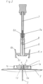
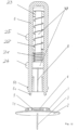
- figure 1 shows an infusion set with a cannula insertion device 3-8 pre-assembled firmly on the base body 1, 2.
- the base body consists of a base body 1 and a plaster 2, which has an adhesive lower surface in order to be able to stick the base body over an injection site.
- the base body 1 is arranged on the upper side of the patch 2; e.g. B. glued, which is fixed by the holder 6a with the cannula insertion device 3 - 8 is connected.
- the cannula insertion device has a guide needle 8 which is guided through the cannula 3 and with which the cannula 3 can be inserted from the underside of the base body 1 into a tissue.
- a holder 5 On the upper side of the cannula 3, ie the side of the cannula 3 facing away from the tip of the guide needle 8, a holder 5 is firmly connected to the cannula 3, with the holder 5, as in FIG figure 3 shown, a sealing element or septum 4 is provided.
- the guide needle 8 and the cannula 3 are surrounded by the guide element 6, which serves as a protective element, so that on the one hand there is no risk of injury to an operator, since the tip of the guide needle 8 does not protrude from the arrangement shown and is still arranged inside the base body 1 or the guide element 6 is.
- the arrangement shown largely prevents contamination of the guide needle 8 and the cannula 3 before the cannula 3 is introduced into the tissue, since direct contact between the cannula 3 and the guide needle 8 and the environment is prevented by the guide element 6 and the base body 1 .
- the guide needle 8 is, as in figure 2 shown, firmly connected to the actuating element 7 and can be pushed out of the base body 1 by pressing the actuating element 7 downwards in order to introduce the cannula 3 into a tissue.
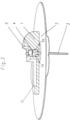
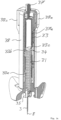
- figure 2 shows the arrangement of figure 1 after inserting the cannula 3 and releasing the connection between the cannula insertion device and the base body.
- the guide needle 8 was pushed downwards together with the cannula 3 and the cannula 3 was introduced into a tissue lying under the patch 2 (not shown).
- the guide needle 8 can be pulled out of the cannula 3 by moving the actuating element 7 upwards without excessive force acting on the inserted cannula 3 during this process of pulling the guide needle 8 out of the cannula 3 .
- the latching of the holder 5 in the base body 1 causes the holder 5 to be firmly anchored in the base body 1 and thus a strain relief when there is an upward force on the guide needle 8 relative to the guide element 6, which is still connected to the base body 1 during the extraction process of the cannula 3 during the withdrawal process of the needle 8 is made possible.
- the holder 5 can, for example, have a surface structure or one or more outwardly protruding elements on the outer surface, which is guided inside the guide element 6, which enable movement of the holder 5 in the extension direction, but prevent or impede movement in the retraction direction that incorrect operation can be prevented.
- corresponding structures or elements can be provided on the inside of the guide element 6 in order to only allow a movement in a predetermined direction.
- the cannula insertion device can be detached from the base body 1.
- the actuating element 7 is firmly latched by a circumferential groove 7a in the lower area of the actuating element 7 with a circumferential projection 6d of the guide element 6 and thus ensures that after the cannula insertion device has been disconnected, the guide needle 8 can no longer be unintentionally removed from the Guide element 6 can be pushed out.
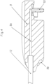
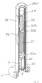
- figure 3 shows in partial section the inserted cannula 3 with the holder 5 locked in the base body 1, in which a sealing element 4 is arranged.
- figure 4 shows a sectional view of the in figure 1 shown plug 9 of the liquid supply device.
- the coupling part 13 of the hose 12 is connected to a liquid delivery device (not shown).
- the entire liquid space of the coupling part 13, the hose 12 and the plug 9 is then flooded.
- the plug has a plug cannula 10 which is connected to the tube 12 by the channel 9a running in the plug 9 .
- the plug 9 is brought into a position above the base body 1, as in figure 5 shown and brought into contact with the edge 1b of the base body 1 with the edge 9b running on the rear lower side of the plug 9 .
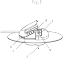
- the plug 9 is preferably tilted slightly upwards, as in figure 6 shown, so that the edge 9b protruding from the plug 9 is introduced into the gap defined by the upper side of the base body 1 and the protruding edge 1c of the base body 1. In this way, the plug 9 can be brought into a first contact position relative to the base body 1 in a relatively simple and user-friendly manner.
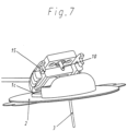
- the plug 9 can be folded down around the pivot point defined by this engagement in order to insert the plug cannula 10 into the housing 5 through the sealing element 4 to be introduced and thus allow a flow of liquid from the liquid delivery device through the coupling part 13, the tube 12, the plug 9 and the plug cannula 10 into the cannula 3 and thus into the surrounding tissue.
- the plug 9 is guided via guide cams 14 in order to insert the plug cannula 10 into the housing 5 in a precise position.
- the guide cams 14 By being guided by means of the guide cams 14, any lateral offset of the plug 9 relative to the base body 1 when the plug 9 is attached to the edge 1b of the base body 1 can be corrected when the plug 9 is folded, so that the plug cannula 10 always fits securely into the housing 5 can be introduced.
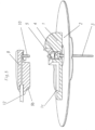
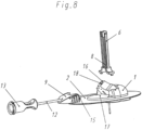
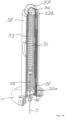
- figure 8 shows an alternative embodiment of the present invention.
- a rotating part 16 rotatably mounted in the base body 1 can be brought into a position in which the opening 18 of the rotating part 16 points upwards.
- a cannula can be introduced into the base body 1 with the aid of the guide needle 8, which is protected by a frame serving as a protective element 6, as described above.
- the guide needle 8 can be removed again.
- the rotary part 16 can now, as in figure 8 shown, turned to the side and locked preferably with an attached to the base plane of the base body 1 upwardly pointing detent 17, whereby the rotating part 16 is securely held in its folded-down position.
- a plug 9 can be attached to the side of the completely folded-down rotary part 16 in such a way that the plug cannula 10 running in a straight extension of the tube 12 can be inserted into the opening 18 of the rotary part 16 pointing to the side.
- a latching device 15 attached to the plug 9 can latch with suitable counterparts of the rotating part 16 .
- the plug 9 can be disconnected from the base body 1 again by lateral pressure on the areas located above or to the side of the latching devices 15 of the plug 9 . After the disconnection has taken place, the sealing element 4 again completely closes the access to the cannula 3 .
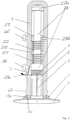
- FIG 9 shows an automatic cannula loading device according to the invention.
- a needle carrier 27 that can be moved in the longitudinal direction of the guide element 6 and is firmly connected to the guide needle 8 .
- the guide needle 8 can also be configured so that it can be coupled to the needle carrier 27, e.g. B. to be able to change the guide needle 8.
- the needle carrier 27 is in a retracted state and is activated by a loading spring abutting the front of the needle carrier 27 21, which is braced against a support element 20 provided approximately in the central part of the guide element 6 and prestresses the needle carrier 27, which is secured by the holding element 28a, in the extension direction of the cannula 3.
- the holding element 28a can be unlocked by a first release button 24 .
- the needle carrier 27 runs in the longitudinal direction of the guide element 6 through the two springs 21 and 22, as well as the support element 20 and the retaining ring 23, and has a retaining element 27a at its rear end to prevent the needle carrier 27 from being pushed through the retaining ring 23 can fully pass through.
- the holding element 28a (shown schematically) is pushed or folded radially outwards in the direction of the arrow, with the folding mechanism preferably being formed entirely within the guide element 6, with the needle carrier 27 then no longer being held in the direction of extension of the cannula 3 and is accelerated downwards by the force of the insertion spring 21 in order to eject the cannula 3 from the guide element 6 with the guide needle 8 and insert it through the patch 2 into a tissue.
- the ejection movement is continued until the holding element 27a of the needle carrier 27 is in contact with the holding ring 23 .
- figure 10 shows the in figure 9 shown cannula insertion device after the cannula 3 has been pushed out.
- the insertion spring 21 has transferred the energy stored in it to the needle carrier 27 and is in the relaxed state.
- the holder 5 can, for. B. as described above, with the base body 1 are locked. If the user now presses the second release button 25, the radially displaceable holding element 28b ( 9 ) is pushed out of the retaining ring 23 and the retaining ring 23, which was previously secured against axial movement in the guide element 6, is released, so that the return spring 22 presses against the retaining ring 23 and the retaining element 27a of the needle carrier 27 and a retraction force thus acts on the needle carrier 27 .
- the return spring 22 is preferably designed in such a way that it can apply a greater force than the insertion spring 21, since this is compressed again when the needle carrier 27 is pulled back.
- the needle carrier 27 can also be designed such that after the cannula 3 has been inserted, there is no longer any coupling between the lower side of the needle carrier 27 and the insertion spring 21, so that the insertion spring 21 no longer has to be tensioned when the needle carrier 27 is pulled back.
- the holding element 28a and/or the holding element 28b can be designed as a tilting or sliding mechanism or as any other securing mechanism.
- figure 11 shows the in figure 10 shown cannula insertion device after the needle carrier 27 has been withdrawn.
- the guide needle 8 was thereby withdrawn from the ejected cannula 3 and introduced into the guide element 6 in order to avoid injuries.
- the triggering of the return spring 22 can take place automatically by unlocking the retaining ring 23 when the cannula insertion device is removed from the base body 1, e.g. B. by pressing the buttons 6b to release the latching of the locking lugs 6c of the guide element 6 with the locking lugs 1a of the base body 1 and at the same time the retaining ring 23 is unlocked.
- the cannula insertion device is advantageously designed in such a way that the locking between the guide element 6 and the base body 1 cannot be released when the guide needle 8 is in the in figure 9 positions shown before extension and/or in the in figure 10 shown extended position.
- This can e.g. B. characterized in that the underside of the needle carrier 27 is so wide that a compression of the underside of the guide element 6 z. B. is prevented on the buttons 6b and in the in figure 10 shown position thus the locking between the guide element 6 and base body 1 can not be released.
- figure 12 shows the cannula insertion device detached from the base body 1 with the guide needle 8 retracted.
- the cannula insertion device can now be safely disposed of since the guide needle 8 is covered by the surrounding guide element 6 and the risk of unintentional puncture injuries is thus minimized.
- the cannula insertion device can be reinserted into the in figure 9 shown state are brought by z. B. the retaining ring 23 is pushed back into a lower position from the upper position, the return spring 22 being tensioned again. It is also possible to push the needle carrier 27 out of the guide element 6 and thereby tension the return spring 22, with the insertion spring 21 then being tensioned again in a second step.
- the used guide needle is preferably exchanged and replaced with a new guide needle, optionally with a new cannula 3 and associated holder 5 with sealing element 4 .
- FIG 13 shows a first embodiment of a Automatic cannula insertion and retraction device in the initial state before inserting a cannula 3 on a cannula assembly 35 through a guide needle 8
- Base body 1 to be attached as shown for one of the embodiments in the previous figures.
- These connector elements 39 for connecting the connector sleeve 38 to a predetermined base body have, for example, latching tongues 39a and other connecting elements (not shown).
- the tongues 33a to 33c are arranged at various positions in the axial direction of the guide sleeve 33, and may be arranged as individual protruding members or over a larger part of the circumference of the guide sleeve 33.
- the tongues can, for example, also lie opposite one another and/or be formed symmetrically to one another as a plurality of individual tongue elements.
- the three tongues 33a to 33c shown by way of example are offset from one another in the axial direction of the guide sleeve 33 in order to fulfill different functions when triggering an extension and retraction process, as will be explained below.
- a release sleeve 37a is fixedly connected to the release button 37 and has recesses in the axial direction, which are assigned to the tongues 33b and 33c. Furthermore, special release surfaces, such as bevels, are provided on the release sleeve 37a in order to prevent the tongues 33a to 33c from moving the release sleeve 37a downwards in the in figure 13 shown embodiment in a predetermined sequence, thereby initiating the extension and retraction process of the cannula assembly 35.
- a needle part or needle carrier 34 is also slidably arranged within the connector sleeve 38 and is coupled to the cannula assembly 35 via a firmly connected guide needle 8 and preferably a direct contact surface or latched to it via a latching device (not shown).
- the fully prestressed spring 31 presses on the cannula assembly 35, with a pair of tongues 33b arranged symmetrically above the spring 31 and a pair of tongues 33a of the guide sleeve 33 arranged below the cannula assembly 35 pressing on the cannula assembly 35 hold position.
- a safety clip 38a with a bore 38b provided therein is provided on the upper side of the connector sleeve 38, the diameter of the bore 38b roughly corresponding to the diameter of the release button 37 and preferably being a little larger in order to allow the release button 37 to easily pass through.
- the approximately L-shaped safety clip 38a is located opposite a safety clip 38c with an elastic element on the upper side of the connector sleeve 38, with a tongue 38d provided on the safety clip 38a being able to latch with the safety clip 38c when the safety clip 38a and the safety clip 38c are pressed together become.
- Bore 38b shown eccentrically to the cannula axis, prevents release button 37 from being pressed.
- the hole 38b is brought into a position concentric to the position of the release button 37 so that it can be pressed.
- figure 14 shows the state of the in figure 13 shown device after the operating button 37 has been depressed by about half a length.
- the lower tongues 33a onto which the cannula assembly 35 has been pressed by the spring 31 are deformed by the release sleeve 37a extending along the inside of the connector sleeve 38, whereby the cannula assembly 35 is released together with the needle carrier 34 and by the spring 31 at one lower end stop, which can be provided in the cannula insertion device or on a base body 1, is pressed.
- the upper end of the needle carrier 34 leads over the tongues 33c.
- the cannula 3 of the cannula assembly 35 connected to the guide needle 8 is pushed out of the device downwards, preferably at high speed, by the force of the spring 31 and can be introduced into a tissue as desired.
- the cannula assembly 35 is locked to an infusion set body or base (not shown) and the needle carrier 34 is unlocked by tabs in the infusion set body so that the needle carrier 34 and cannula assembly are no longer connected (Fig figure 14 Not shown).
- the needle carrier 34 is locked in this position by the two symmetrically arranged tongues 33c, which makes it possible to relocate the set.
- the spring 31 in the semi-relaxed state presses down against the pushed-out cannula assembly 35 and on the opposite side abuts against a protruding element of the needle part 34, the needle part 34 being secured against axial displacement by the tongues 33c.
- the spring 31 is held in the position shown by the tongues 33b.
- the spring can also be retained in the position shown, for example by the upper end of the needle part 34.
- figure 15 shows the state of the device of figure 14 , after the operating knob 37 has been fully depressed.
- the release sleeve 37a is pushed over the tongues 33b and 33c, which are pushed outwards and thus release the needle part 34. which is pushed back into the connector sleeve 38 by the spring 31, which can now fully relax.
- the guide needle 8 connected to the needle part 34 is withdrawn from the cannula 3 and the cannula assembly 35 into the connector sleeve 38, with the cannula 3 z. B. can remain in a tissue.
- the needle part 34 is maintained in the retracted position by the spring 31 so that the guide needle 8 cannot accidentally exit the connector sleeve 38, thereby minimizing the risk of injury.
- the connector sleeve 38 can now be removed from a base body by releasing the connector elements 39 .
- figure 16 shows a second embodiment of an automatic cannula insertion and retraction device in the initial state with a connector sleeve 38 which is connected to a base body 1.
- a release button 37 transitions into the release sleeve 37a, which is arranged within the connector sleeve 38.
- the release sleeve 37a has depressions and lower and upper bevels along its axial direction on the inside, with which a lower and an upper driver ring 32a and 32b can be decoupled when the release sleeve 37a is axially displaced within the connector sleeve 38 in order to remove the guide needle 8 from the Eject connector sleeve 38 together with cannula 3 and associated cannula assembly 35 arranged around it, and then withdraw guide needle 8 from cannula 3 and cannula assembly 35, as will be described below.
- the lower driver ring 32a rests against a stop sleeve 36 and is held in position by this against the pressure of the spring 31.
- the spring 31 presses at the top against the upper driver ring 32b, which z. B. is held in a groove or depression.
- the needle carrier 34 is designed in such a way that it can be moved in the axial direction of the connector sleeve 38 through the driver rings 32a and 32b to the end of the needle carrier 34, which has a larger diameter than the inner diameter of the driver rings, in order to prevent the Needle carrier 34 can fall out, for example.
- the needle carrier 34 is in turn firmly connected to the guide needle 8 .
- figure 17 shows the in figure 16 shown device after the safety cap 38d arranged over the release button 37 has been removed and the release button 37 has been pressed in by about half a length.
- the lower catch ring 32a is displaced laterally away from the stop sleeve 36 by a lower inclined inner surface of the release sleeve 37a and is thus decoupled from it.
- the lower driver ring 32a can either already be coupled to the needle carrier 34 or coupled to the needle carrier 34 by this displacement process.
- the spring 31 now presses against the upper driver ring 32b, which is still held firmly by the guide sleeve 33, and presses the lower driver ring 32a, which is coupled to the needle carrier 34, downwards and thus introduces the guide needle 8 together with the cannula 3 into a tissue below the base body 1 , again moving the cannula assembly 35 to a lower end stop.
- the needle carrier 34 remains locked to the base body 1, which makes it possible to relocate the entire set.
- figure 18 shows the state of the in figure 17 device shown after the release button 37 has been further depressed.
- the needle carrier 34 is completely unlocked from the cannula assembly 35 .
- the upper driver ring 32b is laterally displaced by an upper inclined surface of the release sleeve 37a and is thus decoupled from the guide sleeve 33 and coupled into the needle carrier 34, so that the spring 31 presses the needle carrier 34 upwards via the upper driver ring 32b to an upper end stop can.
- one or more actuators e.g. B. buttons may be provided which directly or indirectly, z. B. via a displacement of an element in the cannula insertion device, the corresponding process z. B. by releasing a spring trigger.
Description
Die vorliegende Erfindung bezieht sich auf ein Infusionsset, insbesondere auf eine Vorrichtung zum Einbringen einer Kanüle in Gewebe, wie z. B. Haut-, Fett- oder Muskelgewebe und weiterhin auf eine Vorrichtung zum Zuführen einer Flüssigkeit über die Kanüle in das Gewebe.The present invention relates to an infusion set, in particular to a device for introducing a cannula into tissue, such as. B. skin, fat or muscle tissue and further to a device for supplying a liquid via the cannula into the tissue.
Aus der
Die
Aus der
Die
Bei den bekannten Vorrichtungen ist die Kanüle entweder relativ ungeschützt gegen unbeabsichtigtes Herausziehen, wobei insbesondere schon beim Ausziehen der Nadel aus der Kanüle eine Zugkraft auf die in das Gewebe eingebrachte Kanüle wirkt, oder es muss eine zusätzliche Vorrichtung während des Einstichvorgangs zusammen mit der Kanüle bewegt werden, was die genaue Positionierung erschwert.In the known devices, the cannula is either relatively unprotected against unintentional withdrawal, in which case a tensile force acts on the cannula introduced into the tissue, in particular when the needle is pulled out of the cannula, or an additional device must be moved together with the cannula during the puncture process , making precise positioning difficult.
Es ist eine Aufgabe der vorliegenden Erfindung eine Vorrichtung vorzuschlagen, welche das Einbringen einer Kanüle verbessert. Allgemein soll ein Infusionsset vorgeschlagen werden, welches Verbesserungen gegenüber dem Stand der Technik aufweist.It is an object of the present invention to propose a device which improves the insertion of a cannula. In general, an infusion set is to be proposed which has improvements over the prior art.
Diese Aufgabe wird gelöst durch die Gegenstände der unabhängigen Ansprüche. Vorteilhafte Ausführungsformen sind in den abhängigen Ansprüchen aufgeführt.This object is solved by the subject matter of the independent claims. Advantageous embodiments are listed in the dependent claims.
Die erfindungsgemäße Vorrichtung zum Einbringen einer Kanüle in ein Gewebe zum bevorzugt subkutanen oder transkutanen Verabreichen einer Flüssigkeit, weist eine Kanüle auf, welche auf bekannte Art einer Führungsnadel in das Gewebe eingebracht wird. Weiterhin ist ein Schutzelement vorgesehen, welches die Kanüle vor dem Einbringen in das Gewebe aufnehmen kann, wobei das Schutzelement bevorzugt so ausgebildet ist, dass die in das Gewebe eindringende Spitze der Kanüle oder auch einer zum Einbringen der Kanüle geeigneten Nadel von dem Schutzelement abgedeckt wird, so dass ein Benutzer nicht versehentlich mit dieser Spitze in Kontakt kommen kann und z. B. durch diese Spitze verletzt wird. Das Schutzelement kann die Spitze der Kanüle zum Teil oder vollständig oder sogar die gesamte Kanüle, gegebenenfalls auch eine zum Einbringen der Kanüle vorgesehene Nadel umgeben, um die Schutzfunktion zu gewährleisten. Es ist weiterhin ein Betätigungselement vorgesehen, mit welchem die Kanüle bzw. die Nadel mit Kanüle aus dem Schutzelement herausbewegt werden kann, um z. B. die Kanüle in das Gewebe einzubringen, wobei es im Falle der Verwendung einer Nadel zum Einbringen der Kanüle bevorzugt wird, dass die Nadel nach dem Einbringen der Kanüle durch das Betätigungselement oder auch automatisch, z. B. unter Verwendung eines Federmechanismus, wieder in das Schutzelement zurückbewegt werden kann, um auch nach dem Einbringen der Kanüle die Verletzungsgefahr zu minimieren bzw. auszuschließen. Erfindungsgemäß ist die Kanüle mit einer Halterung verbunden, welche z. B. am distalen, also dem der Kanülenspitze abgewandten Ende vorgesehen sein kann und welche mit der Kanüle bewegt werden kann und beim Einbringen der Kanüle die Kanüle in einer festen Position fixieren kann, indem z. B. diese Halterung mit einem über der Einstichstelle schon vor dem Einstich fest angeordnetem Grundkörper verrastet oder allgemein mit diesem Grundkörper verbunden wird. Wird z. B. eine Nadel nach dem Einbringen der Kanüle aus dieser herausgezogen, so kann aufgrund der mit der Kanüle verbundenen Halterung sichergestellt werden, dass wenn eine Haltekraft an der Halterung anliegt, z. B. durch Verbinden der Halterung mit einem Grundkörper, die Auszugskraft der Nadel nicht unmittelbar auf die Kanüle wirkt, d. h. dass die Kanüle beim Ausziehen nicht in Auszugsrichtung belastet wird. Erfindungsgemäß ist es möglich durch geeignetes Halten bzw. Befestigen der Halterung die Kanüle beim Ausziehen einer Nadel zu entlasten und die Kanüle gegen unbeabsichtigtes Herausziehen zu sichern. Wird eine Kanüle ohne Verwendung einer Nadel eingebracht, so weist die erfindungsgemäße Halterung den Vorteil auf, dass die eingebrachte Kanüle durch die Halterung und gegebenenfalls ein mit der Halterung verbundenes Element gegen unbeabsichtigtes Herausziehen gesichert werden kann. Mit der erfindungsgemäßen Vorrichtung ist der Einstichvorgang auch einfach und relativ gefahrlos durchzuführen.The device according to the invention for introducing a cannula into a tissue for the preferably subcutaneous or transcutaneous administration of a liquid has a cannula which is introduced into the tissue in the known manner of a guide needle. Furthermore, a protective element is provided which can accommodate the cannula before it is introduced into the tissue, the protective element preferably being designed in such a way that the tip of the cannula penetrating the tissue or of a needle suitable for inserting the cannula is covered by the protective element, so that a user cannot accidentally come into contact with this tip and e.g. B. is injured by this tip. The protective element can partially or completely surround the tip of the cannula or even the entire cannula, optionally also a needle provided for inserting the cannula, in order to ensure the protective function. An actuating element is also provided, with which the cannula or the needle with the cannula can be moved out of the protective element in order to, for. B. to introduce the cannula into the tissue, it being preferred in the case of using a needle for inserting the cannula that the needle after the insertion of the cannula by the actuating element or automatically, z. B. using a spring mechanism, can be moved back into the protective element in order to minimize or exclude the risk of injury even after the insertion of the cannula. According to the invention, the cannula is connected to a holder which z. B. can be provided at the distal, so the end facing away from the cannula tip and which can be moved with the cannula and can fix the cannula in a fixed position when inserting the cannula by z. B. this holder is locked with a fixed body above the puncture site before the puncture or is generally connected to this body. If e.g. B. pulled out a needle after inserting the cannula from this, so can due to the holder connected to the cannula it must be ensured that when a holding force is applied to the bracket, e.g. B. by connecting the holder with a base body, the extraction force of the needle does not act directly on the cannula, ie that the cannula is not loaded in the pull-out direction when it is pulled out. According to the invention, by suitably holding or fastening the holder, it is possible to relieve the cannula when a needle is pulled out and to secure the cannula against unintentional pulling out. If a cannula is inserted without using a needle, the holder according to the invention has the advantage that the inserted cannula can be secured against unintentional pulling out by the holder and possibly an element connected to the holder. With the device according to the invention, the puncture process can also be carried out easily and relatively safely.
Obwohl in dieser Beschreibung von "Ausschieben" einer Nadel oder Kanüle mit einem "Ausschiebeelement" gesprochen wird, wird angemerkt, dass hierunter auch ein Herausziehen mit einem Zugelement verstanden werden soll, d.h. eine Bewegung kann durch eine Zug- und/oder Druckkraft bzw. eine Zug und/oder Druckfeder bewirkt werden.Although this description speaks of "pushing out" a needle or cannula with a "push-out element", it is noted that this should also be understood as a pulling-out with a pulling element, i.e. a movement can be caused by a tensile and/or compressive force or a Train and / or compression spring are effected.
Die mit der Kanüle verbundene Halterung ist so ausgebildet, dass sie eine Verbindung mit einem Basiskörper welcher z. B. auf die Haut über einer Einstichstelle aufgeklebt werden kann, wobei dieser Basiskörper vorteilhaft so angeordnet ist, dass die Verbindung mit der Halterung im vollständig oder fast vollständig ausgeschobenen Zustand der Kanüle erfolgt. Diese Verbindung ist eine Rastverbindung, wobei z. B. eine oder mehrere Nuten bzw. Vertiefung und/oder Vorsprünge oder Rastlippen an der Halterung vorgesehen sein können, welche eine lösbare oder auch nicht mehr lösbare feste Verbindung der Halterung mit einem geeigneten Element ermöglichen.The holder connected to the cannula is designed in such a way that it can be connected to a base body which, e.g. B. can be glued to the skin over a puncture site, this base body is advantageously arranged so that the connection to the holder is made in the fully or almost fully extended state of the cannula. This connection is a locking connection, where z. B. one or more grooves or recesses and / or projections or locking lips can be provided on the bracket, which allow a detachable or non-detachable fixed connection of the bracket with a suitable element.
Bei der Erfindung ist eine Nadel vorgesehen, mit welcher die Kanüle in ein Gewebe eingebracht werden kann, wobei die Nadel von der Kanüle umgeben wird. Dabei ist es besonders vorteilhaft die Vorrichtung so auszugestalten, dass die Nadel nach Einbringen der Kanüle wieder bevorzugt vollständig zurück in das Schutzelement eingebracht werden kann, z. B. durch eine Bewegung des Betätigungselements und/oder eine Feder, welche z. B. beim Einbringen der Kanüle in das Gewebe und Ausfahren der Nadel aus dem Schutzelement komprimiert wird und eine Kraft erzeugt, welche die Nadel zurück in ihre Ausgangslage in das Schutzelement bringt.In the case of the invention, a needle is provided with which the cannula can be introduced into a tissue, the needle being surrounded by the cannula. It is particularly advantageous to design the device in such a way that after the cannula has been inserted, the needle can preferably be completely inserted back into the protective element, e.g. B. by a movement of the actuating element and / or a spring which z. B. is compressed when inserting the cannula into the tissue and extending the needle from the protective element and generates a force which brings the needle back to its original position in the protective element.
Die Vorrichtung ist so ausgestaltet, dass sie lösbar mit einem Basiskörper verbunden werden kann und besonders vorteilhaft in einem Ausgangszustand schon mit dem Basiskörper verbunden ist, so dass die Applikation für den Benutzer vereinfacht wird. Der Basiskörper besteht aus einem auf eine Hautstelle aufklebbarem Pflaster und einem darauf angeordneten Grundkörper, auf welchem die Vorrichtung zum Einbringen der Kanüle angeordnet ist. Bei einer solchen Konfiguration kann die Spitze der Kanüle bzw. der Nadel schon relativ nahe an einer Austrittsöffnung des Basiskörpers angeordnet sein, so dass z. B. nach Aufkleben des Pflasters auf einen Hautbereich die Kanüle bzw. Nadel sofort in die Haut eingebracht werden kann. Dabei kann die Spitze der Kanüle bzw. Nadel auch aus dem Schutzelement herausragen, ohne dass eine Verletzungsgefahr für eine Bedienperson besteht, da die Spitze durch den umgebenden Basiskörper abgeschirmt wird. Die in dem Basiskörper vorgesehene Durchtrittsöffnung für die Spitze der Kanüle bzw. Nadel ist vorteilhaft relativ klein, bevorzugt nur geringfügig größer als der Durchmesser der Kanüle, um ein unbeabsichtigtes Hindurchlangen der Bedienperson durch die Durchtrittsöffnung auszuschließen und somit die Verletzungsgefahr zu minimieren. Nach Einbringen der Kanüle und gegebenenfalls Zurückziehen der Nadel in das Schutzelement kann die Vorrichtung wieder von dem Basiskörper gelöst werden, so dass z. B. eine Flüssigkeitszufuhr mit der Kanüle verbunden werden kann.The device is designed in such a way that it can be detachably connected to a base body and is particularly advantageously already connected to the base body in an initial state, so that application is simplified for the user. The base body consists of a patch that can be stuck to a skin area and a base body arranged thereon, on which the device for inserting the cannula is arranged. With such a configuration, the tip of the cannula or needle can already be arranged relatively close to an outlet opening of the base body, so that z. B. after sticking the patch on a skin area, the cannula or needle can be inserted immediately into the skin. The tip of the cannula or needle can also protrude from the protective element without there being any risk of injury to an operator, since the tip is shielded by the surrounding base body. The passage opening provided in the base body for the tip of the cannula or needle is advantageously relatively small, preferably only slightly larger than the diameter of the cannula, in order to prevent the operator from accidentally reaching through the passage opening and thus to minimize the risk of injury. After inserting the cannula and possibly retracting the needle into the protective element, the device can be detached from the base body again, so that z. B. a liquid supply can be connected to the cannula.
Die Vorrichtung zum Einbringen der Kanüle mit dem Basiskörper, kann mit dem Grundkörper durch eine Rastverbindung verbunden werden, welche auch wieder gelöst werden kann.The device for inserting the cannula with the base body can be connected to the base body by a snap-in connection, which can also be released again.
Bei einer bevorzugten Ausführungsform der Erfindung ist das Schutzelement ein Rahmen, welcher die Kanüle bzw. die Nadel im zurückgezogenen Zustand zumindest teilweise umgibt. Besonders bevorzugt ist das Schutzelement ein Mantel, welcher die Kanüle bzw. Nadel im zurückgezogenen Zustand vollständig umgibt, wobei bevorzugt eine Durchtrittsöffnung in dem Schutzelement vorgesehen ist, durch welches die Kanüle bzw. Nadel aus dem Schutzelement herausbewegt bzw. wieder in das Schutzelement eingebracht werden kann. Diese Durchtrittsöffnung kann offen sein und ist bevorzugt nur geringfügig größer als der Außendurchmesser der Kanüle. Es ist auch möglich die Durchtrittsöffnung durch ein geeignetes Abdeckelement zu verschließen, welches beim Ausfahren der Kanüle bzw. Nadel von der Durchtrittsöffnung wegbewegt werden kann oder auch elastisch ausgebildet ist, so dass z. B. die Kanüle oder Nadel hindurchstechen kann.In a preferred embodiment of the invention, the protective element is a frame which at least partially surrounds the cannula or the needle in the retracted state. The protective element is particularly preferably a jacket which completely surrounds the cannula or needle in the retracted state, with a passage opening preferably being provided in the protective element, through which the cannula or needle can be moved out of the protective element or reinserted into the protective element . This passage opening can be open and is preferably only slightly larger than the outer diameter of the cannula. It is also possible to close the through-opening with a suitable cover element, which can be moved away from the through-opening when the cannula or needle is extended, or is also designed to be elastic, so that z. B. can pierce the cannula or needle.
Vorteilhaft ist die Vorrichtung so ausgestaltet, dass das Betätigungselement oder auch ein zum Einbringen der Kanüle vorgesehenes Nadelelement im zurückgezogenen Zustand nach Einbringen der Kanüle mit dem Schutzelement verbunden, insbesondere verrastet werden kann, so dass ein versehentliches Wiederausschieben der Nadel aus dem Schutzelement verhindert wird und somit eine unbeabsichtigte Verletzung einer Bedienperson ausgeschlossen werden kann.The device is advantageously designed in such a way that the actuating element or also a needle element provided for inserting the cannula can be connected, in particular locked, to the protective element in the retracted state after the cannula has been inserted, so that the needle is prevented from being accidentally pushed out of the protective element again and thus accidental injury to an operator can be ruled out.
Besonders bevorzugt ist die Vorrichtung, insbesondere das Betätigungselement so ausgebildet, dass im ausgeschobenen Zustand der Kanüle ein Lösen der Vorrichtung zum Einbringen der Kanüle von einem mit der Vorrichtung verbundenen Basiskörper verhindert werden kann. Hierzu kann z. B. ein mit dem Betätigungselement verbundenes und verschiebbares Querelement vorgesehen sein, welches im ausgeschobenen Zustand der Kanüle z. B. ein Zusammendrücken von für die Verbindung mit dem Basiskörper vorgesehenen Halteelementen verhindert und somit eine z. B. nur durch Zusammendrücken dieser Halteelemente zu erreichende Loslösung der Vorrichtung von dem Basiskörper ausgeschlossen werden kann. Allgemein kann jede Anordnung bzw. jedes Element verwendet werden, welches eine solche Sicherungsfunktion bieten kann. Hierdurch kann sichergestellt werden, dass nicht versehentlich die Kanülen-Einbringvorrichtung vom Basiskörper gelöst wird, wenn z. B. eine Nadel aus dem Schutzelement ausgefahren ist, was zu Verletzungen einer Bedienperson führen könnte.The device, in particular the actuating element, is particularly preferably designed in such a way that the cannula is released when it is in the extended state Device for inserting the cannula can be prevented by a base body connected to the device. For this purpose z. B. may be provided with the actuating element connected and displaceable transverse element, which in the extended state of the cannula z. B. prevents compression of intended for the connection with the base body holding elements and thus a z. B. to be achieved detachment of the device from the base body can be excluded only by squeezing these holding elements. In general, any arrangement or any element that can offer such a security function can be used. This can ensure that the cannula insertion device is not accidentally released from the base body when z. B. a needle is extended from the protective element, which could lead to injury to an operator.
Bevorzugt ist in der Halterung ein Dichtelement oder Septum zum Abschließen der Kanülenoberseite bzw. eines Flüssigkeitsraumes vorgesehen, welches z. B. von einer Nadel und/oder einer Flüssigkeitszufuhr durchdrungen werden kann und eine flüssigkeitsdichte Verbindung gewährleisten kann. Ist kein Element in das Septum eingebracht, so kann es den Zugang zur Kanüle oder einem über der Kanüle liegenden Flüssigkeitsraum vollständig verschließen. Geeignete Materialien hierzu sind im Stand der Technik bekannt.A sealing element or septum is preferably provided in the holder to close off the upper side of the cannula or a liquid space. B. can be penetrated by a needle and / or a liquid supply and can ensure a liquid-tight connection. If no element is introduced into the septum, it can completely close off access to the cannula or a liquid space above the cannula. Suitable materials for this are known in the prior art.
Gemäß einem anderen Aspekt der Erfindung ist ein Basiskörper vorgesehen, welcher z. B. aus einem auf eine Hautstelle aufklebbarem Pflaster und einem darauf angeordneten Grundkörper besteht, wobei der Basiskörper bzw. der Grundkörper mindestens ein lösbares Verbindungselement aufweist, an welchem die oben beschriebenen Vorrichtung zum Einbringen einer Kanüle angebracht werden kann und an welchem eine Vorrichtung zum Zuführen eines Fluids bzw. einer Flüssigkeit angebracht werden kann, so dass wenn der Basiskörper über einer Einbringstelle der Kanüle angebracht ist, an dem Basiskörper sowohl die Vorrichtung zum Einbringen der Kanüle, als auch eine Vorrichtung zum Zuführen eines Fluids zusammen oder nacheinander an den gleichen oder verschiedenen Verbindungselementen angebracht werden können. Dabei kann bevorzugt im Ausgangszustand die Vorrichtung zum Einbringen der Kanüle schon fest und lösbar mit dem Basiskörper verbunden sein, so dass der Basiskörper mit der Einbringvorrichtung für die Kanüle zusammen über einer Einbringstelle der Kanüle angebracht werden kann, wobei die Einbringvorrichtung nach erfolgtem Einbringen der Kanüle von dem Basiskörper wieder abgelöst werden kann. Es ist auch möglich den Basiskörper erst vor dem Einbringen der Kanüle mit der Kanülen-Einbringvorrichtung zu verbinden.According to another aspect of the invention, a base body is provided which z. B. consists of a patch that can be glued to a skin area and a base body arranged thereon, the base body or the base body having at least one detachable connecting element to which the device for inserting a cannula described above can be attached and to which a device for feeding a Fluids or a liquid can be attached, so that when the base body is attached to an insertion point of the cannula, both the device for inserting the cannula and a device for supplying a fluid together or successively to the same or different connecting elements on the base body can be attached. The device for inserting the cannula can preferably already be firmly and detachably connected to the base body in the initial state, so that the base body can be attached together with the insertion device for the cannula over an insertion point of the cannula, with the insertion device being removed after the cannula has been inserted by can be detached again from the base body. It is also possible to connect the base body to the cannula insertion device only before the cannula is inserted.
Vorteilhaft dient das mindestens eine am Basiskörper vorgesehene Verbindungselement sowohl zur Verbindung mit der Einbringvorrichtung für die Kanüle, als auch zur Verbindung mit der Vorrichtung zum Zuführen eines Fluids, so dass z. B. nach Ablösen der Einbringvorrichtung für die Kanüle die Vorrichtung zum Zuführen des Fluids an dem bzw. den gleichen Verbindungselementen angebracht werden kann, welches bzw. welche zuvor zum Befestigen der Einbringvorrichtung für die Kanüle gedient haben.Advantageously, the at least one connection element provided on the base body is used both for connection to the insertion device for the cannula and for connection to the device for supplying a fluid, so that z. B. after detachment of the insertion device for the cannula, the device for supplying the fluid can be attached to the same connection element or elements which have previously been used to attach the insertion device for the cannula.
Das mindestens eine am Basiskörper vorgesehene Verbindungselement ist eine Rastverbindung, also insbesondere eine Nut und/oder eine Rastlippe bzw. Rastnase mit welcher eine Rastverbindung mit der Einbringvorrichtung für die Kanüle und z.B. auch mit der Fluidzuführvorrichtung hergestellt werden kann.The at least one connecting element provided on the base body is a snap-in connection, i.e. in particular a groove and/or a snap-in lip or snap-in nose with which a snap-in connection with the insertion device for the cannula and e.g. also with the fluid supply device can be established.
Gemäß einem weiteren Aspekt der vorliegenden Erfindung wird ein System vorgeschlagen, mit welchem eine Flüssigkeitszufuhr mit einer Kanüle verbunden werden kann, wobei ein Grundkörper vorgesehen ist, welcher eine Kanüle aufweist, die bevorzugt schon in ein Gewebe eingebracht ist, z. B. unter Verwendung der oben beschriebenen Vorrichtung. Der Grundkörper hat mindestens eine Öffnung, welche mit der Kanüle bzw. dem Kanülenholraum in Verbindung steht. Zur Zufuhr der Flüssigkeit ist ein Stecker mit einem Zuführelement vorgesehen, welches in die Öffnung des Grundkörpers eingebracht werden kann, so dass die Flüssigkeit über das Zuführelement durch die Öffnung des Grundkörpers in den Kanülenholraum und somit in das Gewebe geleitet werden kann. Erfindungsgemäß kann der Stecker an einem Anlagepunkt des Grundkörpers angelegt und so um den Anlagepunkt geklappt werden, dass das Zuführelement des Steckers in die Öffnung des Grundkörpers geführt wird. Ein solches Verbinden bzw. Konnektieren des Steckers einer Flüssigkeitszufuhr mit der Kanüle ist vorteilhaft, da keine exakte Positionierung am Anfang des Verbindungsvorganges erforderlich ist, d. h. dass z. B. in ihrer körperlichen Leistungsfähigkeit eingeschränkte Benutzer den Stecker relativ einfach an einem Anlagepunkt des Grundkörpers anlegen können, wobei der Anlagepunkt kein Punkt im geometrischen Sinne sein muss, sondern auch als Anlagekante mit geradem oder auch gebogenem bzw. abgewinkeltem Verlauf oder als Anlagefläche ausgebildet sein kann. Wird ein solcher Stecker z. B. mit einer Anlagekante bzw. einem geeigneten Vorsprung des Steckers an einer Anlagekante des Grundkörpers angelegt, was noch nicht mit großer Genauigkeit bezüglich der Anlageposition erfolgen muss, so kann z. B. durch geeignete Führungen der Stecker beim Klappen um diese Anlagekante allmählich in die exakte Position gebracht werden, so dass das Zuführelement bei vollständig niedergeklapptem Stecker exakt in die Öffnung des Grundkörpers eingebracht werden kann. Diese Art der Verbindung eines Steckers mit dem Grundkörper ist somit bezüglich des Ansatzes des Steckers am Grundkörper relativ fehlertolerant und ist insbesondere dann von großem Vorteil, wenn die mit dem Grundkörper verbundene Kanüle wie oben beschrieben durch eine bereits fest mit dem Grundkörper verbundene Einbringvorrichtung für die Kanüle eingeführt wurde. In diesem Fall muss die Einbringvorrichtung für die Kanüle vom Benutzer nach dem Einbringen der Kanüle lediglich von dem Grundkörper gelöst werden, was keinen genauen Positionierungsvorgang erfordert, so dass der einzige Positionierungsvorgang, welcher vom Benutzer ausgeführt werden muss, das fehlertolerante Anbringen des Steckers an dem Anlagepunkt des Grundkörpers ist, wobei bevorzugt über eine geeignete Führung beim Klappen des Steckers das Zuführelement positionsgenau in die Öffnung des Grundkörpers gebracht wird.According to a further aspect of the present invention, a system is proposed with which a liquid supply can be connected to a cannula, a base body being provided which has a cannula which is preferably already introduced into a tissue, e.g. B. using the device described above. The base body has at least one opening which is connected to the cannula or the cannula cavity. To supply the liquid, a plug with a feed element is provided, which can be introduced into the opening of the base body, so that the liquid can be fed via the feed element through the opening of the base body into the cannula cavity and thus into the tissue. According to the invention, the plug can be placed on a contact point of the base body and folded around the contact point in such a way that the feed element of the plug is guided into the opening of the base body. Such a connection or connection of the connector of a liquid supply with the cannula is advantageous because no exact positioning at the beginning of the connection process is required, ie that z. B. Users with limited physical ability can place the plug relatively easily on a contact point of the base body, whereby the contact point does not have to be a point in the geometric sense, but can also be designed as a contact edge with a straight or curved or angled course or as a contact surface . If such a plug z. B. created with a contact edge or a suitable projection of the connector on a contact edge of the body, which does not have to be done with great accuracy with respect to the system position, so z. B. are gradually brought into the exact position by suitable guides of the plug when folding around this contact edge, so that the feed element can be introduced exactly into the opening of the base body when the plug is completely folded down. This type of connection of a plug to the base body is therefore relatively fault-tolerant with regard to the attachment of the plug to the base body and is particularly advantageous if the cannula connected to the base body, as described above, is replaced by an insertion device for the cannula that is already firmly connected to the base body was introduced. In this case, the cannula insertion device must be provided by the user only be detached from the base body after the cannula has been inserted, which does not require an exact positioning process, so that the only positioning process that has to be carried out by the user is the fault-tolerant attachment of the plug to the contact point of the base body, preferably using a suitable guide when Flaps of the connector, the feeding element is brought into the opening of the base body in a precise position.
Bevorzugt ist mindestens ein Führungselement am Grundkörper und/oder am Stecker vorgesehen, um den Stecker während des Klappvorgangs nach dem Anlegen an dem Anlagepunkt bzw. einer Anlagekante zu führen. Als Führungselement kann z. B. eine sich in der Breite verjüngende Rille vorgesehen sein, in welche ein Vorsprung eingreift, so dass der Vorsprung bei dem Klappvorgang entlang der Rille in Richtung auf das schmalere Ende geführt wird, wodurch eine genaue Positionierung des Steckers relativ zum Grundkörper erfolgen kann. Sowohl die Rille, als auch der Stecker können dabei an dem Grundkörper und/oder dem Stecker vorgesehen sein. Weiterhin ist es auch denkbar, seitliche Führungen an den Stecker und/oder dem Grundkörper vorzusehen, welche trichterförmig ausgebildet sind, um so die gewünschte Positionierung des Steckers relativ zu dem Grundkörper zu erzielen. Allgemein ist jedoch jede Anordnung geeignet, welche es ermöglicht, dass der an mindestens einem Anlagepunkt anliegende Stecker bei einem Klappvorgang geführt und dabei im niedergeklappten Zustand genau positioniert werden kann.
Bevorzugt ist der Stecker so ausgebildet, dass er mit dem Anlagepunkt bzw. einer Anlagekante des Grundkörpers verhaken kann. Unter Verhaken wird im Sinne der Erfindung verstanden, dass der Stecker an einem Punkt oder mehreren Punkten, Kanten oder Flächen des Grundkörpers anliegt und so eine lose Verbindung zwischen Stecker und Grundkörper geschaffen wird, welche ein Klappen bzw. eine Drehbewegung um diese Verbindung ermöglichen. Dabei soll bevorzugt mindestens ein Freiheitsgrad in der Bewegung des Steckers relativ zum Grundkörper eingeschränkt werden, so dass nach Einhaken des Steckers in den Grundkörper eine erste Grobpositionierung des Steckers in Bezug auf den Grundkörper erfolgt.At least one guide element is preferably provided on the base body and/or on the plug in order to guide the plug during the folding process after it has been placed on the contact point or a contact edge. As a guide element z. B. a width-tapering groove can be provided, into which a projection engages, so that the projection is guided during the folding process along the groove in the direction of the narrower end, whereby the plug can be precisely positioned relative to the base body. Both the groove and the plug can be provided on the base body and/or the plug. Furthermore, it is also conceivable to provide lateral guides on the plug and/or the base body, which are funnel-shaped in order to achieve the desired positioning of the plug relative to the base body. In general, however, any arrangement is suitable which makes it possible for the plug lying against at least one contact point to be guided during a folding process and to be positioned precisely in the folded-down state.
The plug is preferably designed in such a way that it can hook onto the contact point or a contact edge of the base body. In the context of the invention, hooking is understood to mean that the plug rests against one point or several points, edges or surfaces of the base body and a loose connection is thus created between the plug and base body, which allows folding or a rotary movement around this connection. At least one degree of freedom in the movement of the plug relative to the base body should preferably be limited, so that after the plug has been hooked into the base body, the plug is first roughly positioned in relation to the base body.
Besonders bevorzugt kann der Stecker mit dem Grundkörper verbunden werden, z. B. verrasten, wobei hierzu geeignete Nuten, Rastnasen oder Ähnliches vorgesehen sein können. Die Verbindung bzw. Rastverbindung kann lösbar oder unlösbar ausgestaltet sein.The plug can particularly preferably be connected to the base body, e.g. B., for which purpose suitable grooves, locking lugs or the like can be provided. The connection or latching connection can be detachable or non-detachable.
Gemäß einem weiteren Aspekt der Erfindung weist ein Grundkörper ein drehbar gelagertes Drehteil auf, welches bevorzugt fest mit dem Grundkörper verbunden ist. Das Drehteil hat eine bevorzugt durch ein Dichtungselement abgeschlossene Öffnung, welche in einer ersten Position des Drehteils das Einführen einer Kanüle z. B. mit einer Nadel ermöglicht und in einer zweiten gedrehten Position das Einführen eines Zuführelements zum Zuführen von Flüssigkeit ermöglicht. Das Vorsehen eines Drehteils am Grundkörper bringt den Vorteil mit sich, dass z. B. bei Ausrichtung der Öffnung des Drehteiles nach oben, also in eine Richtung bei welcher die Öffnung auf einer Verlängerung der gewünschten Position der einzubringenden Kanüle liegt, die Kanüle durch die Öffnung des Drehteils und durch den Grundkörper hindurch direkt in das Gewebe eingebracht werden kann. Nach erfolgtem Einbringen der Kanüle und gegebenenfalls dem Loslösen der Einbringvorrichtung der Kanüle kann das Drehteil gedreht werden, so dass seitlich bzw. bei nicht nach oben weisender Öffnung des Drehteils ein Zuführelement zum Zuführen von Flüssigkeit angeschlossen werden kann. Somit kann auf einfache Weise eine Kanüle eingebracht werden und eine Flüssigkeitszufuhr seitlich angeschlossen werden, wodurch die Gesamthöhe der Vorrichtung bei eingebrachter Kanüle und angeschlossener Flüssigkeitszufuhr gering bleibt. Die Verbindung der Kanüle mit der Öffnung des Drehteils kann z. B. durch ein flexibles Schlauchelement oder eine andere geeignete Vorrichtung erfolgen, welche eine sichere Verbindung im gedrehten Zustand des Drehteils ermöglicht.According to a further aspect of the invention, a base body has a rotatably mounted rotary part which is preferably firmly connected to the base body. The rotating part has an opening which is preferably closed off by a sealing element and which, in a first position of the rotating part, allows the insertion of a cannula, e.g. B. allows with a needle and in a second rotated position allows the insertion of a delivery element for the delivery of liquid. The provision of a rotating part on the body has the advantage that z. B. when aligning the opening of the rotary part upwards, i.e. in a direction in which the opening is on an extension of the desired position of the cannula to be inserted, the cannula can be inserted directly into the tissue through the opening of the rotary part and through the base body. After the cannula has been inserted and, if necessary, the cannula insertion device has been detached, the rotating part can be rotated so that a supply element for supplying liquid can be connected laterally or when the opening of the rotating part is not pointing upwards. A cannula can thus be introduced in a simple manner and a liquid supply can be connected laterally, as a result of which the overall height of the device with the cannula inserted and the liquid supply connected remains low. The connection of the cannula with the opening of the rotating part can, for. B. by a flexible hose element or other suitable device, which allows a secure connection in the rotated state of the rotary part.
Gemäß einem weiteren Aspekt der Erfindung weist eine Vorrichtung zum Zuführen einer Flüssigkeit über eine Kanüle in ein Gewebe nur ein einziges Dichtungselement auf, welches zur Abdichtung eines Flüssigkeitsraumes dient und von einer Kanüle und/oder einer Nadel durchstochen werden kann, wenn die Kanüle in das Gewebe eingebracht werden soll und von einem Zuführelement durchdrungen werden kann, wenn dem Flüssigkeitsraum eine Flüssigkeit zugeführt werden soll. Ergänzend können natürlich auch weitere Dichtungselemente vorgesehen sein.According to a further aspect of the invention, a device for supplying a liquid via a cannula into a tissue has only a single sealing element, which is used to seal a liquid space and can be pierced by a cannula and/or a needle when the cannula is inserted into the tissue is to be introduced and can be penetrated by a feed element when a liquid is to be fed to the liquid space. Of course, additional sealing elements can also be provided.
Nach einem Aspekt der Erfindung kann eine Flüssigkeit über eine Kanüle einem Gewebe zugeführt werden, wobei eine Kanüle, gegebenenfalls mit Nadel, durch ein Dichtungselement gestochen wird, um die Kanüle in das Gewebe einzubringen. Ist die Kanüle eingebracht, so wird ein Zuführelement, gegebenenfalls nach Entfernen der Nadel, durch das Dichtungselement eingebracht, um über das Zuführelement durch das Dichtungselement und die Kanüle hindurch eine Flüssigkeit in das Gewebe einzubringen.According to one aspect of the invention, a liquid can be supplied to a tissue via a cannula, with a cannula, optionally with a needle, being pierced through a sealing element in order to introduce the cannula into the tissue. Once the cannula has been inserted, a delivery element is inserted through the sealing element, optionally after removing the needle, in order to introduce a liquid into the tissue via the delivery element, through the sealing element and the cannula.
Gemäß einem weiteren Aspekt der Erfindung wird eine Vorrichtung zum Einbringen einer Kanüle in Gewebe vorgeschlagen, wobei eine Kanülenausschubvorrichtung zum Ausschieben der Kanüle und Einbringen der Kanüle in Gewebe vorgesehen ist. Erfindungsgemäß ist ein Rückzugelement mit der Kanülenausschubvorrichtung gekoppelt, um die Kanülenausschubvorrichtung nach dem Ausschieben der Kanüle wieder zurückzuziehen. Das Rückzugelement ist bevorzugt eine Feder, welche beispielsweise so vorgespannt sein kann, dass die in der Feder gespeicherte Energie bzw. Kraft ausreicht die Kanülenausschubvorrichtung aus dem ausgeschobenen Zustand wieder zurückzuziehen, wobei ein vollständiges Zurückziehen in den Ausgangszustand möglich aber nicht erforderlich ist. Somit kann erfindungsgemäß die Applikation einer Kanüle automatisiert und damit vereinfacht werden. Durch geeignete Wahl der Parameter des Rückzugelements, wie z.B. einer Federlänge und einer Federkonstante, kann der Rückzugsvorgang der Kanülenausschubvorrichtung sicher durchgeführt werden, d.h. es steht bei richtiger Wahl dieser Parameter immer eine ausreichende Kraft zur Verfügung, um das Rückzugelement sicher zurückzuziehen, ohne dass ein Benutzer manuell eine große Kraft aufwenden muss.According to a further aspect of the invention, a device for inserting a cannula into tissue is proposed, with a cannula ejection device being provided for ejecting the cannula and inserting the cannula into tissue. According to the invention, a retraction element is coupled to the cannula ejection device in order to retract the cannula ejection device again after the cannula has been ejected. The retraction element is preferably a spring, which can be pretensioned such that the energy or force stored in the spring is sufficient to retract the cannula push-out device from the pushed-out state, complete retraction to the initial state being possible but not necessary. Thus, according to the invention the application of a cannula can be automated and thus simplified. By suitably choosing the parameters of the retraction element, such as a spring length and a spring constant, the retraction process of the cannula ejection device can be carried out safely, i.e. if these parameters are correctly selected, there is always sufficient force available to safely retract the retraction element without a user has to exert a great deal of force manually.
Bevorzugt ist die Kanülenausschubvorrichtung eine Führungsnadel oder ein anderes die Kanüle tragende Element. So kann z. B. eine Kanüle ohne Führungsnadel mittels einer geeigneten Kanülenhalterung eingebracht werden.The cannula ejection device is preferably a guide needle or another element carrying the cannula. So e.g. B. a cannula without a guide needle can be inserted using a suitable cannula holder.
Als Rückzugelement ist bevorzugt eine Feder vorgesehen, wobei auch andere Energie- oder Kraft speichernde Elemente erfindungsgemäß eingesetzt werden können, um das Rückzugelement nach Einbringen der Kanüle wieder zurückzuziehen.A spring is preferably provided as the retraction element, whereby other energy or force-storing elements can also be used according to the invention in order to retract the retraction element again after the cannula has been inserted.
Bevorzugt ist ein Auslöseelement für das Rückzugelement vorgesehen, welches z. B. manuell bedient werden kann oder bei einem bestimmten Zustand der Kanüleneinbringvorrichtung automatisch ausgelöst wird. Als manuelles Auslöseelement kann z. B. ein Druckknopf oder ein geeignetes anderes Schalt- oder Schiebeelement vorgesehen sein, mit welchem eine Sicherung des Rückzugelements entsichert werden kann. Als Sicherung kann z. B. ein das Rückzugelement in Rückzugrichtung blockierendes Halteelement vorgesehen sein, welches bei Auslösen der Sicherung, z. B. dem Drücken eines Druckknopfes, so verschoben wird, dass über das Rückzugelement eine Rückzugkraft an die Kanülenausschubvorrichtung angelegt wird, um diese zurückzuziehen. Das Halteelement kann z. B. ein seitlich verschiebbares Element, wie z. B. ein Stift oder eine Kante sein und kann z. B. auch über einen Kipp- oder Klappmechanismus bewegt werden.A trigger element for the retraction element is preferably provided, which z. B. can be operated manually or triggered automatically in a certain state of the cannula insertion device. As a manual trigger element z. B. a push button or another suitable switching or sliding element can be provided with which a fuse of the retraction element can be unlocked. As a backup z. B. be provided a retaining element blocking the retraction element in the direction of retraction, which when the fuse is triggered, z. B. pressing a push button, is displaced so that a retraction force is applied to the cannula ejection device via the retraction element in order to retract it. The holding element can, for. B. a laterally displaceable element such. B. be a pen or an edge and can z. B. can also be moved via a tilting or folding mechanism.
Vorteilhaft kann das Auslöseelement für das Rückzugelement automatisch bei einem bestimmten Zustand der Kanüleneinbringvorrichtung ausgelöst werden. Zum Beispiel kann ein Mechanismus vorgesehen sein, welcher den Rückzugsvorgang der Kanülenausschubvorrichtung automatisch einleitet, wenn z. B. die Kanüleneinbringvorrichtung von einem Grundkörper abgenommen wird. Hierzu kann z. B. eine Nocke am Grundkörper vorgesehen sein, welche beim Abnehmen der Kanüleneinbringvorrichtung vom Grundkörper automatisch einen Auslösemechanismus für das Rückzugelement betätigt.Advantageously, the triggering element for the retraction element can be triggered automatically when the cannula insertion device is in a specific state. For example, a mechanism can be provided which automatically initiates the retraction process of the cannula ejector when z. B. the cannula insertion device is removed from a base body. For this purpose z. For example, a cam can be provided on the base body, which automatically actuates a trigger mechanism for the retraction element when the cannula insertion device is removed from the base body.
Vorteilhaft kann auch ein Ausschubelement, z. B. eine Feder vorgesehen sein, welche eine ausreichende Kraft erzeugen kann, um die Kanüle in das Gewebe einzubringen. Das Ausschubelement kann wie oben für das Rückzugelement beschrieben gesichert sein und z. B. ebenfalls durch einen Druckknopf ausgelöst werden. Bei Vorsehen sowohl eines Rückzugelements, als auch eines Ausschubelements kann eine vollautomatische Kanüleneinbringvorrichtung geschaffen werden, da ein Benutzer weder zum Einbringen einer Kanüle, noch zum Zurückziehen einer Kanülenausschubvorrichtung aktiv Kraft aufwenden muss. Das Einbringen einer Kanüle z. B. mit einer Führungsnadel und das Zurückziehen der Führungsnadel wird somit voll automatisiert, so dass die Gefahr einer falschen Anwendung durch Benutzer verringert wird.A slide-out element, e.g. B. a spring can be provided which can generate sufficient force to introduce the cannula into the tissue. The extension element can be secured as described above for the retraction element and z. B. can also be triggered by a push button. If both a retraction element and an ejection element are provided, a fully automatic cannula insertion device can be created, since a user does not have to actively exert force either to insert a cannula or to withdraw a cannula ejection device. The introduction of a cannula z. B. with a guide needle and the retraction of the guide needle is thus fully automated, so that the risk of incorrect use by users is reduced.
Die Vorrichtung zum Einbringen einer Kanüle in Gewebe kann vorteilhaft so ausgestaltet sein, dass ein einziges energiespeicherndes Element, wie z. B. eine Feder oder auch eine Mehrzahl von zusammenwirkenden energiespeichernden Elementen als eine energiespeichernde Einheit eingesetzt werden, um eine Kanülenausschubvorrichtung oder Nadel, bevorzugt nach dem geeigneten Positionieren, automatisch, d.h. ohne Zuführen von externer Energie, so zu bewegen, dass die Kanüle in das Gewebe eingebracht wird und die Kanülenausschubvorrichtung anschließend ebenfalls ohne externe Kraft- oder Energiezufuhr automatisch wieder in das Gewebe eingebrachten Kanüle herausgezogen wird, so dass ein Benutzer, außer zum Auslösen der jeweiligen Ausschub- und Rückzieh-Vorgänge, im wesentlichen keine Kraft aufwenden muss. Dabei ist es vorteilhaft bei Verwendung einer einzigen energiespeichernden Vorrichtung, wie beispielsweise einer Druckfeder, die Feder im Ausgangszustand, d.h. vor Einbringen der Kanüle in Gewebe, in einem gespannten Zustand so anzuordnen, dass bei einer ersten Teilentspannung oder Teilausdehnung der Feder in eine erste Richtung, beispielsweise zum Ausschieben der Kanülenausschubvorrichtung oder Nadel aus der Kanüleneinbringvorrichtung nach unten, die Kanülenausschubvorrichtung oder Nadel soweit aus der Kanüleneinbringvorrichtung herausbewegt wird, dass die Kanüle oder eine Kanülenbaugruppe wie gewünscht in oder auf einem Gewebe plaziert werden können, wobei bei einer zweiten Teilausdehnung der Feder in eine zweite Richtung, bevorzugt entgegengesetzt zur ersten Richtung, die Kanülenausschubvorrichtung oder Nadel wieder zurückgezogen wird, so dass die Kanüle oder die Kanülenbaugruppe im Gewebe verbleiben kann und die Kanüleneinbringvorrichtung mit bevorzugt vollständig eingezogener Kanülenausschubvorrichtung oder Nadel abgenommen werden kann. Statt einer Feder, welche beispielsweise aus Metall oder Kunststoff gefertigt sein kann, können als Energiespeicher auch andere Elemente verwendet werden, welche beispielsweise Druckluft speichern, auf elektrischen, magnetischen oder anderen Prinzipien basieren.The device for inserting a cannula in tissue can advantageously be designed so that a single energy-storing element, such as. B. a spring or a plurality of interacting energy-storing elements can be used as an energy-storing unit to move a cannula ejection device or needle, preferably after suitable positioning, automatically, i.e. without supplying external energy, so that the cannula into the tissue is introduced and the cannula ejection device is then automatically pulled out again from the cannula introduced into the tissue, also without an external force or energy supply, so that a user essentially does not have to exert any force, except for triggering the respective extension and retraction processes. When using a single energy-storing device, such as a compression spring, it is advantageous to arrange the spring in a tensioned state in the initial state, i.e. before inserting the cannula into the tissue, in such a way that when the spring partially relaxes or partially expands in a first direction, for example, to eject the cannula ejector or needle down from the cannula insertion device, the cannula ejector or needle is moved out of the cannula insertion device to such an extent that the cannula or a cannula assembly can be placed in or on a tissue as desired, with a second partial extension of the spring in a second direction, preferably opposite to the first direction, the cannula ejection device or needle is withdrawn again so that the cannula or the cannula assembly can remain in the tissue and the cannula insertion device can be removed with the cannula ejection device or needle preferably fully retracted. Instead of a spring, which can be made of metal or plastic, for example, other elements can also be used as energy stores, which store compressed air, for example, based on electrical, magnetic or other principles.
Bevorzugt ist ein einziges Auslöseelement, wie beispielsweise ein Knopf, Schalter, Klappmechanismus, Schiebemechanismus, Rastmechanismus, Drehmechanismus, Drehknopf oder Hebel vorgesehen, mit welchem je nach Stellung der Ausschub-Vorgang und der Rückzieh-Vorgang der Kanülenausschubvorrichtung oder Nadel ausgelöst werden können. Beispielsweise kann ein Knopf in Form eines einschiebbaren oder drückbaren Elements vorgesehen sein, welcher z. B. nach Durchführen eines Entsicherungs-Vorganges eine erste Teilstrecke gedrückt wird, um den Ausschub-Vorgang auszulösen und in der gleichen Richtung eine zweite Teilstrecke mit gleicher oder unterschiedlicher Länge gedrückt wird, um den Rückzugvorgang auszulösen. Alternativ ist es auch möglich, dass das eine Auslöseelement zum Auslösen des Ausschubvorgangs in eine erste Richtung betätigt wird und zum Auslösen des Rückzug-Vorgangs der Kanülenausschubvorrichtung oder Nadel in eine zweite Richtung bewegt wird, welche von der ersten Richtung verschieden ist, wie z. B. eine Bewegung in die entgegengesetzte Richtung. Somit kann mit einem einzigen Auslöseelement, wie beispielsweise einem Druccknopf, durch Drücken des Druckknopfes z. B. in eine einzige Richtung nacheinander zunächst das Einbringen der Kanüle in Gewebe durch die Kanülenausschubvorrichtung oder Nadel und anschließend das Rückziehen der Nadel aus der eingebrachten Kanüle oder Kanülenbaugruppe veranlasst werden, wodurch die Kanüleneinbringvorrichtung sehr einfach bedient werden kann.A single triggering element, such as a button, switch, folding mechanism, sliding mechanism, locking mechanism, rotary mechanism, rotary knob or lever is preferably provided, with which the ejection process and the retraction process of the cannula ejection device or needle can be triggered depending on the position. For example, a button can be provided in the form of a retractable or depressible element which z. B. after performing an arming process a first leg is pressed to trigger the extension process and a second section of the same or different length is pressed in the same direction to trigger the retraction process. Alternatively, it is also possible that one triggering element is actuated in a first direction to trigger the ejection process and is moved in a second direction, which is different from the first direction, to trigger the retraction process of the cannula ejection device or needle, e.g. B. a movement in the opposite direction. Thus, with a single trigger element, such as a push button, by pressing the push button z. B. in a single direction sequentially first the insertion of the cannula into tissue through the cannula ejection device or needle and then the withdrawal of the needle from the introduced cannula or cannula assembly can be caused, whereby the cannula insertion device can be operated very easily.
Allgemein kann ein Auslöseelement auch als ein Drehmechanismus oder Drehknopf ausgebildet sein, wobei durch eine Drehung ein Ausschub-Vorgang ausgelöst werden kann und bei einem Weiterdrehen in die gleiche oder alternativ in die entgegengesetzte Richtung ein Rückzug-Vorgang ausgelöst wird. Es sind auch Kombinationen unterschiedlicher Auslöseelemente möglich, um z.B. mit einem Druckknopf oder Schalter einen Ausschub-Vorgang auszulösen und z.B. mit einem Drehknopf einen Rückzug-Vorgang auszulösen. Vorteilhaft wird ein Auslöseelement für das Rückziehen erst nach erfolgtem Ausschieben freigegeben.In general, a triggering element can also be designed as a rotary mechanism or rotary knob, wherein a rotation can trigger an extension process and a further rotation in the same or alternatively in the opposite direction triggers a retraction process. Combinations of different triggering elements are also possible, e.g. to trigger an extension process with a push button or switch and e.g. to trigger a retraction process with a rotary knob. Advantageously, a triggering element for retraction is released only after it has been pushed out.
Vorteilhaft kann mindestens ein Sicherungselement an der Kanüleneinbringvorrichtung vorgesehen sein, welches ein unbeabsichtigtes Betätigen eines Auslöseelements verhindert. Ein solches Sicherungselement ist beispielsweise so ausgestaltet, dass es von der Kanüleneinbringvorrichtung abgenommen oder an der Kanüleneinbringvorrichtung in einen entsicherten Zustand gebracht werden muss, um überhaupt das Auslöseelement betätigen zu können. Beispielsweise kann das Sicherungselement als eine Sicherungskappe ausgestaltet sein, welche das Auslöseelement zumindest teilweise und bevorzugt in etwa vollständig umgibt und vor unbeabsichtigter Berührung und somit ungewünschter Auslösung schützt. Weiterhin kann das Sicherungselement auch als eine Vorrichtung zum Sperren oder Arretieren des Auslöseelements ausgestaltet sein, welche beispielsweise erst verschoben werden muss, um das Auslöseelement betätigen zu können. Dabei ist es vorteilhaft das Sicherungselement so auszugestalten, dass es nicht einfach z. B. durch eine unbeabsichtigte Berührung oder einen Stoß bewegt werden kann, sondern beispielsweise nur durch eine Druckbewegung zwischen zwei Fingern in einen Zustand gebracht werden kann, in welchem das Auslöseelement betätigt werden kann. Dabei kann das Sicherungselement so ausgestaltet sein, dass es entweder einen konstanten Druck oder Zug benötigt, um das Auslöseelement in den entsicherten Zustand zu versetzen, oder das es nach Durchführen eines Entsicherungsvorgangs in dem entsicherten Zustand bleibt und beispielsweise einrastet, so dass nach dem Entsichern das Auslöseelement betätigt werden kann.Advantageously, at least one safety element can be provided on the cannula insertion device, which prevents unintentional actuation of a triggering element. Such a safety element is designed, for example, in such a way that it must be removed from the cannula insertion device or brought into an unlocked state on the cannula insertion device in order to be able to actuate the triggering element at all. For example, the safety element can be designed as a safety cap, which at least partially and preferably approximately completely surrounds the triggering element and protects it from accidental contact and thus undesired triggering. Furthermore, the securing element can also be designed as a device for blocking or locking the triggering element, which, for example, must first be displaced in order to be able to actuate the triggering element. It is advantageous to design the fuse element so that it is not easy z. B. can be moved by an unintentional touch or a bump, but can be brought into a state in which the trigger element can be actuated, for example, only by a pressing movement between two fingers. The securing element can be designed in such a way that it either requires constant pressure or tension to put the triggering element into the unlocked state, or that it remains in the unlocked state after an unlocking process has been carried out and, for example, engages so that after unlocking the Release element can be actuated.
Die Kanüleneinbringvorrichtung kann als Einwegvorrichtung ausgebildet sein, wobei das darin enthaltene Rückzugelement und/oder Ausschubelement schon vorgespannt sind, um ein automatisches Einbringen der Kanüle und/oder ein automatisches Rückziehen der Kanülenausschubvorrichtung zu bewirken. Die Kanüleneinbringvorrichtung kann jedoch auch als Mehrweg-Kanüleneinbringvorrichtung ausgebildet sein, wobei das Rückzugelement und/oder das Ausschubelement als ladbar bzw. spannbar ausgebildet sind. So kann z. B. ein Mechanismus vorgesehen sein, um eine Rückzugfeder und/oder eine Ausschubfeder nach erfolgtem Einbringen einer Kanüle und/oder Zurückziehen einer Kanülenausschubvorrichtung wieder zu spannen, so dass die Kanüleneinbringvorrichtung zum Einbringen einer weiteren Kanüle verwendet werden kann.The cannula insertion device can be designed as a disposable device, with the retraction element and/or ejection element contained therein already being prestressed in order to bring about automatic insertion of the cannula and/or automatic retraction of the cannula ejection device. However, the cannula insertion device can also be designed as a reusable cannula insertion device, with the retraction element and/or the push-out element being designed to be loadable or tensionable. So e.g. For example, a mechanism can be provided to tension a return spring and/or an ejector spring after a cannula has been inserted and/or a cannula ejector retracted, so that the cannula inserter can be used to insert another cannula.
Allgemein kann erfindungsgemäß die Kanüleneinbringvorrichtung voll automatisch ausgestaltet werden, also sowohl ein Ausschubelement für die Kanüle, als auch ein Rückzugelement vorgesehen sein. Alternativ ist es auch möglich nur eines dieser beiden Elemente vorzusehen, um eine halbautomatische Kanüleneinbringvorrichtung zu schaffen, wobei dann der jeweils andere Vorgang manuell durchgeführt werden muss. Es ist z. B. möglich nur das Einbringen der Kanüle durch Vorsehen eines Ausschubelements zu automatisieren, wobei das Zurückziehen der Kanülenausschubvorrichtung dann manuell durchgeführt werden muss.In general, according to the invention, the cannula insertion device can be designed to be fully automatic, ie both an ejection element for the cannula and a retraction element can be provided. Alternatively, it is also possible to provide only one of these two elements in order to create a semi-automatic cannula insertion device, in which case the respective other process then has to be carried out manually. It is Z. B. possible to automate only the insertion of the cannula by providing an ejection element, the retraction of the cannula ejection device then has to be carried out manually.
Alle beschriebenen Ausführungsformen eines Infusionssets bzw. einer Kanüleneinbringvorrichtung und/oder einer Flüssigkeitszuführvorrichtung können abweichend von den voranstehend beispielhaft beschriebenen Rastverbindungen zum Verbinden der jeweiligen Vorrichtungen mit einem Grundkörper auch eine Dreh- oder Schraubverbindung aufweisen, welche bevorzugt in einer oder mehreren Stellungen verrasten können, so dass die jeweiligen Vorrichtungen durch Drehen miteinander verbunden bzw. voneinander gelöst werden können.All the described embodiments of an infusion set or a cannula insertion device and/or a liquid supply device can, in deviation from the snap-in connections described above by way of example for connecting the respective devices to a base body, also have a rotary or screw connection, which can preferably snap in one or more positions, so that the respective devices can be connected to one another or detached from one another by turning.
Die oben beschriebenen Vorrichtungen gemäß den einzelnen Aspekten der Erfindung können sowohl unabhängig voneinander, als auch in Kombination mit Elementen gemäß anderen Aspekten der Erfindung verwendet werden.The devices according to the individual aspects of the invention described above can be used both independently of one another and in combination with elements according to other aspects of the invention.
Die Erfindung wird nachfolgend anhand bevorzugter Ausführungsbeispiele unter Bezugnahme auf die Zeichnungen beschrieben werden. Es zeigen:
Figur 1- eine erste Ausführungsform eines erfindungsgemäßen Infusionssets einer an einem Basiskörper angebrachten Vorrichtung zum Einbringen der Kanüle;
Figur 2- die
Vorrichtung nach Figur 1 , wobei die Kanüleneinbringvorrichtung vom Basiskörper losgelöst ist; Figur 3- eine Teilschnittansicht des Basiskörpers mit eingebrachter Kanüle;
Figur 4- eine Querschnittsansicht einer Flüssigkeitszuführvorrichtung;
Figur 5- eine Teilquerschnittsansicht der in den Basiskörper einzubringenden Flüssigkeitszuführvorrichtung;
Figur 6- die
Anordnung nach Figur 5 mit an dem Basiskörper angesetztem Stecker der Flüssigkeitszuführvorrichtung; Figur 7- die
Anordnung von Figur 6 aus einem anderem Blickwinkel; Figur 8- eine alternative Ausführungsform der Erfindung mit Drehteil;
Figur 9- eine Ausführungsform einer automatischen Kanüleneinbringvorrichtung im Ausgangszustand;
Figur 10- die in
Figur 9 - Figur 11
- die in
Figur 10 Figur 12- die in
Figur 11 gezeigte Kanüleneinbringvorrichtung nach Abtrennung von dem Grundkörper; Figur 13- eine erste Ausführungsform einer automatischen Kanüleneinbring- und Rückzugsvorrichtung im Ausgangszustand;
Figur 14- die
Vorrichtung von Figur 13 nach Einbringen der Kanüle; Figur 15- die in
Figur 14 Figur 16- eine zweite Ausführungsform einer automatischen Kanüleneinbring- und Rückzugsvorrichtung im Ausgangszustand;
Figur 17- die in
Figur 16 Figur 18- die in
Figur 17
- figure 1
- a first embodiment of an infusion set according to the invention of a device attached to a base body for inserting the cannula;
- figure 2
- the device
figure 1 , wherein the cannula inserter from the base body is detached; - figure 3
- a partial sectional view of the base body with inserted cannula;
- figure 4
- a cross-sectional view of a liquid supply device;
- figure 5
- a partial cross-sectional view of the liquid supply device to be introduced into the base body;
- figure 6
- according to the arrangement
figure 5 with the plug of the liquid supply device attached to the base body; - figure 7
- the arrangement of
figure 6 from a different angle; - figure 8
- an alternative embodiment of the invention with rotary part;
- figure 9
- an embodiment of an automatic cannula insertion device in the initial state;
- figure 10
- in the
figure 9 cannula insertion device shown after insertion of the cannula; - figure 11
- in the
figure 10 cannula insertion device shown after retraction of the guide needle; - figure 12
- in the
figure 11 cannula insertion device shown after separation from the main body; - figure 13
- a first embodiment of an automatic cannula insertion and withdrawal device in the initial state;
- figure 14
- the device of
figure 13 after insertion of the cannula; - figure 15
- in the
figure 14 device shown after withdrawal of the guide needle; - figure 16
- a second embodiment of an automatic cannula insertion and withdrawal device in the initial state;
- figure 17
- in the
figure 16 device shown after insertion of the cannula; and - figure 18
- in the
figure 17 device shown after withdrawal of the guide needle.
Die Halterung 5 kann z.B. an der Außenfläche, welche im Inneren des Führungselements 6 geführt wird eine Oberflächenstruktur oder ein oder mehrere nach außen abstehende Elemente, aufweisen, welche eine Bewegung der Halterung 5 in Ausschubrichtung ermöglichen, jedoch eine Bewegung in Rückzugrichtung verhindern oder erschweren, so dass eine Fehlbedienung verhindert werden kann. Entsprechend können an der Innenseite des Führungselements 6 korrespondierende Strukturen oder Elemente vorgesehen sein, um eine Bewegung nur in eine vorgegebene Richtung zu ermöglichen.The
Werden die Halter 6a des Führungselements 6 durch Zusammendrücken der Betätigungselemente 6b so bewegt, dass die Rastnasen 6c des Führungselements 6 nicht mehr in die Rastnasen 1a des Grundkörpers 1 eingreifen, so kann die Kanülen-Einbringvorrichtung von dem Grundkörper 1 abgelöst werden. Das Betätigungselement 7 ist in seiner äußersten oberen Stellung durch eine im unteren Bereicht des Betätigungselements 7 umlaufende Nut 7a fest mit einem umlaufende Vorsprung 6d des Führungselements 6 verrastet und stellt somit sicher, dass nach Diskonnektieren der Kanülen-Einbringvorrichtung die Führungsnadel 8 nicht mehr unbeabsichtigt aus dem Führungselement 6 ausgeschoben werden kann. Wie aus
Wird der Stecker 9 aus der in den
Im vollständig heruntergeklappten Zustand des Steckers 9, in welchem die Steckerkanüle 10 in das Gehäuse 5 eingeführt ist, verrasten die seitlich am Stecker 9 vorgesehenen Rastvorrichtungen 15 mit den in
Bei den oben beschriebenen Ausführungsformen kann der Stecker 9 jeweils wieder durch seitlichen Druck auf die oberhalb oder seitlich der Rastvorrichtungen 15 des Steckers 9 liegenden Bereiche wieder vom Grundkörper 1 diskonnektiert werden. Nach erfolgter Diskonnektion schließt das Dichtelement 4 den Zugang zur Kanüle 3 wieder vollständig.In the above-described embodiments, the
Allgemein kann das Halteelement 28a und/oder das Halteelement 28b als Kipp- oder Schiebemechanismus oder als ein beliebiger anderer Sicherungsmechanismus ausgebildet sein.In general, the holding element 28a and/or the holding element 28b can be designed as a tilting or sliding mechanism or as any other securing mechanism.
Alternativ zu der gezeigten Ausführungsform kann z. B. das Zurückziehen des Nadelträgers 27 voll automatisch nach Einbringen der Kanüle 3 erfolgen, indem z. B. durch die Unterseite des Nadelträgers 27 ein Auslösemechanismus für die Rückzugfeder 22 betätigt wird, wodurch unmittelbar nach Einbringen der Kanüle 3 der Nadelträger 27 wieder zurückgezogen wird. In diesem Fall kann dann der zweite Auslöseknopf 25 entfallen.As an alternative to the embodiment shown, for. B. the retraction of the
Gemäß einer weiteren alternativen Ausführungsform kann die Auslösung der Rückzugfeder 22 durch Entsichern des Halterings 23 automatisch erfolgen, wenn die Kanüleneinbringvorrichtung von dem Grundkörper 1 abgenommen wird, z. B. indem durch das Eindrücken der Knöpfe 6b um die Verrastung der Rastnasen 6c des Führungselements 6 mit den Rastnasen 1a des Grundkörpers 1 zu lösen auch gleichzeitig der Haltering 23 entsichert wird.According to a further alternative embodiment, the triggering of the
Vorteilhaft ist die Kanüleneinbringvorrichtung so ausgestaltet, dass das Lösen der Verrastung zwischen Führungselement 6 und Grundkörper 1 nicht erfolgen kann, wenn die Führungsnadel 8 in der in
In der in
Die Feder 31 im halbentspannten Zustand drückt unten gegen die ausgeschobene Kanülenbaugruppe 35 und liegt an der gegenüberliegenden Seite an einem vorstehenden Element des Nadelteiles 34 an, wobei das Nadelteil 34 gegen eine axiale Verschiebung durch die Zungen 33c gesichert ist. Die Feder 31 wird in der gezeigten Position durch die Zungen 33b gehalten. Allgemein kann die Feder auch in der gezeigten Position z.B. von dem oberen Ende des Nadelteiles 34 gehalten werden.The
Der untere Mitnehmerring 32a liegt an einer Anschlaghülse 36 an und wird von dieser gegen den Druck der Feder 31 in Position gehalten. Die Feder 31 drückt an der Oberseite gegen den oberen Mitnehmerring 32b, welche durch die Führungshülse 33 z. B. in einer Rille oder Vertiefung gehalten wird. Der Nadelträger 34 ist so ausgestaltet, dass er in axialer Richtung der Konnektorhülse 38 durch die Mitnehmerringe 32a und 32b hindurch bewegt werden kann bis zum Ende des Nadelträgers 34, welcher einen größeren Durchmesser aufweist als der Innendurchmesser der Mitnehmerringe, um so zu verhindern, dass der Nadelträger 34 beispielsweise herausfallen kann. Der Nadelträger 34 ist wiederum fest mit der Führungsnadel 8 verbunden.The
Claims (12)
- Device for introducing a cannula (3) into tissue, comprising:a) a cannula (3), wherein a needle (8) is provided which is surrounded by the cannula (3);b) a protective element (6), which can accommodate the cannula (3);c) an actuating element (7), with which the needle (8) with cannula (3) can be advanced out of the protective element (6);d) a holder (5), which is fixedly attached to the cannula (3), ande) a base body (1, 2), wherein the base body consists of a main body (1) arranged on a patch (2), wherein the device is connected to the base body (1, 2), wherein the connection is releasable, and wherein the device has at least one catch element (6c) for locking to the base body in order to produce the releasable connection,f) wherein the holder (5) has a further catch device (5a) for locking of the holder (5) in the base body (1, 2).
- Device according to Claim 1, wherein the needle (8) can be introduced completely into the protective element (6).
- Device according to Claim 1 or 2, wherein a spring element or an actuating element is provided, generating a force on the needle (8) in the insertion direction into the protective element (6).
- Device according to any one of the preceding claims, wherein the protective element (6) is a solid nondeformable body.
- Device according to any one of the preceding claims, wherein the protective element (6) is a frame, which at least partially surrounds the cannula (3) and/or the needle (8) in the retracted state.
- Device according to any one of Claims 1 to 4, wherein the protective element (6) is a jacket, which completely surrounds the cannula (3) and/or the needle (8) in the retracted state.
- Device according to any one of the preceding claims, wherein the actuating element (7) and/or the needle (8) may be connected to the protective element (6) in the retracted state, in particular so that it can be locked.
- Device according to any one of Claims 1 and 4 to 7, wherein the actuating element (7) is formed in such a way that it prevents the release of the connection to the main body (1) before and/or in the extracted state of the cannula (3).
- Device according to any one of the preceding claims, wherein a sealing element (4) is provided in the holder (5).
- Base body (1, 2) having a main body (1) with at least one catch connection element (1a, 1b) for releasable connection to the device (3-8) for introducing a cannula (3) according to any one of Claims 1 to 10 and/or for releasable connection to a device (9-13) for supplying a fluid, wherein the base body has an additional catch connection element (1d), which can be connected to a holder (5) that is connected to a cannula (3), wherein the additional catch connection element (1d) is designed as an annular projection (1d) for engagement in a groove (5a) extending around the holder (5).
- Base body according to Claim 10, wherein the base body (1, 2) is connected to the device (3-8) for introducing the cannula (3) and the actuating element (7) is preferably at least partially inserted into the protective element (6).
- Base body according to Claim 10 or 11, wherein the same catch connection element (1a, 1b) can be used for connection to the device (3-8) for introducing a cannula (3) and to the device (9-13) for supplying the fluid.
Priority Applications (2)
| Application Number | Priority Date | Filing Date | Title |
|---|---|---|---|
| EP16198978.5A EP3210637B1 (en) | 2001-04-06 | 2002-04-03 | Infusion set |
| DK16198978.5T DK3210637T3 (en) | 2001-04-06 | 2002-04-03 | Infusion set |
Applications Claiming Priority (5)
| Application Number | Priority Date | Filing Date | Title |
|---|---|---|---|
| DE10117285.0A DE10117285B4 (en) | 2001-04-06 | 2001-04-06 | cannula system |
| DE10117285 | 2001-04-06 | ||
| DE20110059U DE20110059U1 (en) | 2001-04-06 | 2001-06-19 | infusion |
| DE20110059U | 2001-06-19 | ||
| PCT/CH2002/000186 WO2002081012A2 (en) | 2001-04-06 | 2002-04-03 | Infusion set |
Related Child Applications (2)
| Application Number | Title | Priority Date | Filing Date |
|---|---|---|---|
| EP16198978.5A Division-Into EP3210637B1 (en) | 2001-04-06 | 2002-04-03 | Infusion set |
| EP16198978.5A Division EP3210637B1 (en) | 2001-04-06 | 2002-04-03 | Infusion set |
Publications (3)
| Publication Number | Publication Date |
|---|---|
| EP1383560A2 EP1383560A2 (en) | 2004-01-28 |
| EP1383560B1 EP1383560B1 (en) | 2016-11-16 |
| EP1383560B2 true EP1383560B2 (en) | 2023-04-26 |
Family
ID=26009025
Family Applications (2)
| Application Number | Title | Priority Date | Filing Date |
|---|---|---|---|
| EP02704544.2A Expired - Lifetime EP1383560B2 (en) | 2001-04-06 | 2002-04-03 | Infusion set |
| EP16198978.5A Expired - Lifetime EP3210637B1 (en) | 2001-04-06 | 2002-04-03 | Infusion set |
Family Applications After (1)
| Application Number | Title | Priority Date | Filing Date |
|---|---|---|---|
| EP16198978.5A Expired - Lifetime EP3210637B1 (en) | 2001-04-06 | 2002-04-03 | Infusion set |
Country Status (5)
| Country | Link |
|---|---|
| US (3) | US7879010B2 (en) |
| EP (2) | EP1383560B2 (en) |
| JP (1) | JP4450556B2 (en) |
| DK (1) | DK3210637T3 (en) |
| WO (1) | WO2002081012A2 (en) |
Families Citing this family (528)
| Publication number | Priority date | Publication date | Assignee | Title |
|---|---|---|---|---|
| US6607509B2 (en) | 1997-12-31 | 2003-08-19 | Medtronic Minimed, Inc. | Insertion device for an insertion set and method of using the same |
| US8177762B2 (en) | 1998-12-07 | 2012-05-15 | C. R. Bard, Inc. | Septum including at least one identifiable feature, access ports including same, and related methods |
| US6562001B2 (en) | 2000-01-21 | 2003-05-13 | Medtronic Minimed, Inc. | Microprocessor controlled ambulatory medical apparatus with hand held communication device |
| AU2002245588A1 (en) * | 2001-03-04 | 2002-09-19 | Sterling Medivations, Inc. | Infusion hub assembly and fluid line disconnect system |
| EP1383560B2 (en) | 2001-04-06 | 2023-04-26 | F. Hoffmann-La Roche AG | Infusion set |
| US7306578B2 (en) | 2002-01-04 | 2007-12-11 | Deka Products Limited Partnership | Loading mechanism for infusion pump |
| US8152789B2 (en) | 2001-10-23 | 2012-04-10 | Medtronic Minimed, Inc. | System and method for providing closed loop infusion formulation delivery |
| US6830562B2 (en) | 2001-09-27 | 2004-12-14 | Unomedical A/S | Injector device for placing a subcutaneous infusion set |
| US10080529B2 (en) | 2001-12-27 | 2018-09-25 | Medtronic Minimed, Inc. | System for monitoring physiological characteristics |
| US20030229308A1 (en) * | 2002-06-05 | 2003-12-11 | Israil Tsals | Injector adapter and combination thereof |
| WO2004020021A2 (en) * | 2002-08-30 | 2004-03-11 | Sterling Medivations, Inc. | Injector for a subcutaneous infusion set |
| US20040051019A1 (en) | 2002-09-02 | 2004-03-18 | Mogensen Lasse Wesseltoft | Apparatus for and a method of adjusting the length of an infusion tube |
| US7381184B2 (en) | 2002-11-05 | 2008-06-03 | Abbott Diabetes Care Inc. | Sensor inserter assembly |
| DK200201823A (en) | 2002-11-26 | 2004-05-27 | Maersk Medical As | Connection piece for a hose connection |
| DE10255817A1 (en) | 2002-11-29 | 2004-06-17 | Disetronic Licensing Ag | Catheter head with lockable sealing element |
| EP1475113A1 (en) * | 2003-05-08 | 2004-11-10 | Novo Nordisk A/S | External needle inserter |
| EP1624914B1 (en) | 2003-05-08 | 2008-04-16 | Novo Nordisk A/S | Internal needle inserter |
| JP4509100B2 (en) | 2003-05-08 | 2010-07-21 | ノボ・ノルデイスク・エー/エス | Infusion device attachable to skin with removable needle insertion actuation |
| US6926694B2 (en) * | 2003-05-09 | 2005-08-09 | Medsolve Technologies, Llc | Apparatus and method for delivery of therapeutic and/or diagnostic agents |
| EP1502613A1 (en) * | 2003-08-01 | 2005-02-02 | Novo Nordisk A/S | Needle device with retraction means |
| US7920906B2 (en) | 2005-03-10 | 2011-04-05 | Dexcom, Inc. | System and methods for processing analyte sensor data for sensor calibration |
| KR20060099520A (en) * | 2003-10-21 | 2006-09-19 | 노보 노르디스크 에이/에스 | Medical skin mountable device |
| EP2179754B1 (en) | 2003-10-23 | 2016-06-01 | Novo Nordisk A/S | Medical injection device mountable to the skin |
| USD902408S1 (en) | 2003-11-05 | 2020-11-17 | Abbott Diabetes Care Inc. | Analyte sensor control unit |
| US7731691B2 (en) * | 2003-11-10 | 2010-06-08 | Smiths Medical Asd, Inc. | Subcutaneous infusion device and device for insertion of a cannula of an infusion device and method |
| US7699808B2 (en) | 2003-11-10 | 2010-04-20 | Smiths Medical Asd, Inc. | Subcutaneous infusion device and method |
| US7850658B2 (en) | 2003-11-10 | 2010-12-14 | Smiths Medical Asd, Inc. | Subcutaneous infusion device and method including release feature for adhesive portion |
| US7699807B2 (en) * | 2003-11-10 | 2010-04-20 | Smiths Medical Asd, Inc. | Device and method for insertion of a cannula of an infusion device |
| US7309326B2 (en) * | 2003-11-18 | 2007-12-18 | Icu Medical, Inc. | Infusion set |
| US9247900B2 (en) | 2004-07-13 | 2016-02-02 | Dexcom, Inc. | Analyte sensor |
| US7670314B2 (en) * | 2004-02-17 | 2010-03-02 | Children's Hospital Medical Center | Injection device for administering a vaccine |
| EP1566193A1 (en) * | 2004-02-18 | 2005-08-24 | Unomedical a/s | Infusion device provided with septum housing |
| CA2560784A1 (en) | 2004-03-26 | 2005-10-06 | Unomedical A/S | Infusion set |
| EP1732626A1 (en) | 2004-03-30 | 2006-12-20 | Novo Nordisk A/S | Actuator system comprising lever mechanism |
| US8792955B2 (en) | 2004-05-03 | 2014-07-29 | Dexcom, Inc. | Transcutaneous analyte sensor |
| FR2869806B1 (en) * | 2004-05-07 | 2007-04-27 | Perouse Soc Par Actions Simpli | INJECTION DEVICE WITH EXTRACTION MECHANISM |
| GB2414775B (en) | 2004-05-28 | 2008-05-21 | Cilag Ag Int | Releasable coupling and injection device |
| GB2414402B (en) | 2004-05-28 | 2009-04-22 | Cilag Ag Int | Injection device |
| GB2414400B (en) * | 2004-05-28 | 2009-01-14 | Cilag Ag Int | Injection device |
| DE102004026806B4 (en) * | 2004-06-02 | 2006-05-24 | Disetronic Licensing Ag | Catheter head with movable connector |
| US7585287B2 (en) | 2004-06-16 | 2009-09-08 | Smiths Medical Md, Inc. | Device and method for insertion of a cannula of an infusion device |
| US7640048B2 (en) | 2004-07-13 | 2009-12-29 | Dexcom, Inc. | Analyte sensor |
| US8565848B2 (en) | 2004-07-13 | 2013-10-22 | Dexcom, Inc. | Transcutaneous analyte sensor |
| US20060270922A1 (en) | 2004-07-13 | 2006-11-30 | Brauker James H | Analyte sensor |
| US7713574B2 (en) * | 2004-07-13 | 2010-05-11 | Dexcom, Inc. | Transcutaneous analyte sensor |
| US8062250B2 (en) | 2004-08-10 | 2011-11-22 | Unomedical A/S | Cannula device |
| US20060100581A1 (en) * | 2004-08-13 | 2006-05-11 | Mogensen Lasse W | Reservoir for front end loaded infusion device |
| DE102004039408A1 (en) * | 2004-08-13 | 2006-03-02 | Disetronic Licensing Ag | Insertion head for medical or pharmaceutical applications |
| US20080215006A1 (en) | 2004-09-22 | 2008-09-04 | Novo Nordisk A/S | Medical Device with Transcutaneous Cannula Device |
| US20090012472A1 (en) * | 2004-09-22 | 2009-01-08 | Novo Nordisk A/S | Medical Device with Cannula Inserter |
| DE202004017861U1 (en) * | 2004-11-17 | 2005-02-17 | Clinico Gmbh | Extraction device for the protected extraction of a flexible puncture needle from a catheter, in particular a catheter with flexible retention tube |
| US7303543B1 (en) * | 2004-12-03 | 2007-12-04 | Medtronic Minimed, Inc. | Medication infusion set |
| WO2006061027A2 (en) | 2004-12-10 | 2006-06-15 | Unomedical A/S | Cannula inserter |
| US20060142798A1 (en) * | 2004-12-27 | 2006-06-29 | Holman Thomas J | Device and method for closing an opening in a body cavity or lumen |
| US9398882B2 (en) | 2005-09-30 | 2016-07-26 | Abbott Diabetes Care Inc. | Method and apparatus for providing analyte sensor and data processing device |
| US9259175B2 (en) | 2006-10-23 | 2016-02-16 | Abbott Diabetes Care, Inc. | Flexible patch for fluid delivery and monitoring body analytes |
| US7883464B2 (en) | 2005-09-30 | 2011-02-08 | Abbott Diabetes Care Inc. | Integrated transmitter unit and sensor introducer mechanism and methods of use |
| US9743862B2 (en) | 2011-03-31 | 2017-08-29 | Abbott Diabetes Care Inc. | Systems and methods for transcutaneously implanting medical devices |
| US8333714B2 (en) | 2006-09-10 | 2012-12-18 | Abbott Diabetes Care Inc. | Method and system for providing an integrated analyte sensor insertion device and data processing unit |
| US8512243B2 (en) | 2005-09-30 | 2013-08-20 | Abbott Diabetes Care Inc. | Integrated introducer and transmitter assembly and methods of use |
| US10226207B2 (en) | 2004-12-29 | 2019-03-12 | Abbott Diabetes Care Inc. | Sensor inserter having introducer |
| US9788771B2 (en) | 2006-10-23 | 2017-10-17 | Abbott Diabetes Care Inc. | Variable speed sensor insertion devices and methods of use |
| US8571624B2 (en) | 2004-12-29 | 2013-10-29 | Abbott Diabetes Care Inc. | Method and apparatus for mounting a data transmission device in a communication system |
| US8029441B2 (en) | 2006-02-28 | 2011-10-04 | Abbott Diabetes Care Inc. | Analyte sensor transmitter unit configuration for a data monitoring and management system |
| US9572534B2 (en) | 2010-06-29 | 2017-02-21 | Abbott Diabetes Care Inc. | Devices, systems and methods for on-skin or on-body mounting of medical devices |
| US7731657B2 (en) * | 2005-08-30 | 2010-06-08 | Abbott Diabetes Care Inc. | Analyte sensor introducer and methods of use |
| US7697967B2 (en) | 2005-12-28 | 2010-04-13 | Abbott Diabetes Care Inc. | Method and apparatus for providing analyte sensor insertion |
| US20090105569A1 (en) | 2006-04-28 | 2009-04-23 | Abbott Diabetes Care, Inc. | Introducer Assembly and Methods of Use |
| JP2008528087A (en) * | 2005-01-24 | 2008-07-31 | ノボ・ノルデイスク・エー/エス | Skin puncture device assembly |
| US9474888B2 (en) | 2005-03-04 | 2016-10-25 | C. R. Bard, Inc. | Implantable access port including a sandwiched radiopaque insert |
| US8029482B2 (en) | 2005-03-04 | 2011-10-04 | C. R. Bard, Inc. | Systems and methods for radiographically identifying an access port |
| US7947022B2 (en) | 2005-03-04 | 2011-05-24 | C. R. Bard, Inc. | Access port identification systems and methods |
| WO2006096686A1 (en) | 2005-03-04 | 2006-09-14 | C.R. Bard, Inc. | Access port identification systems and methods |
| US7985199B2 (en) * | 2005-03-17 | 2011-07-26 | Unomedical A/S | Gateway system |
| GB2424836B (en) * | 2005-04-06 | 2010-09-22 | Cilag Ag Int | Injection device (bayonet cap removal) |
| GB2425062B (en) | 2005-04-06 | 2010-07-21 | Cilag Ag Int | Injection device |
| GB2427826B (en) * | 2005-04-06 | 2010-08-25 | Cilag Ag Int | Injection device comprising a locking mechanism associated with integrally formed biasing means |
| US10307581B2 (en) | 2005-04-27 | 2019-06-04 | C. R. Bard, Inc. | Reinforced septum for an implantable medical device |
| WO2006116613A1 (en) * | 2005-04-27 | 2006-11-02 | C.R. Bard, Inc. | Infusion apparatuses |
| EP3173121B8 (en) | 2005-04-27 | 2021-03-24 | C.R. Bard Inc. | Infusion apparatuses provided with septum |
| US8512288B2 (en) | 2006-08-23 | 2013-08-20 | Medtronic Minimed, Inc. | Infusion medium delivery device and method with drive device for driving plunger in reservoir |
| US8277415B2 (en) | 2006-08-23 | 2012-10-02 | Medtronic Minimed, Inc. | Infusion medium delivery device and method with drive device for driving plunger in reservoir |
| US7905868B2 (en) * | 2006-08-23 | 2011-03-15 | Medtronic Minimed, Inc. | Infusion medium delivery device and method with drive device for driving plunger in reservoir |
| US7665424B2 (en) * | 2005-07-06 | 2010-02-23 | Strategic Applications, Inc. | Harness interface conduit, tether line, and swivel for use in animals |
| DE602005018480D1 (en) | 2005-08-30 | 2010-02-04 | Cilag Gmbh Int | Needle device for a prefilled syringe |
| PL1762259T3 (en) | 2005-09-12 | 2011-03-31 | Unomedical As | Inserter for an infusion set with a first and second spring units |
| DK1968677T3 (en) | 2005-09-15 | 2019-07-15 | Hoffmann La Roche | Insertion head with needle guard in the handle |
| EP1764126B1 (en) | 2005-09-15 | 2010-07-14 | F.Hoffmann-La Roche Ag | Injection head with handle |
| DE502005009907D1 (en) | 2005-09-15 | 2010-08-26 | Roche Diagnostics Gmbh | Insertion head with handle |
| US7534226B2 (en) | 2005-09-26 | 2009-05-19 | M2 Group Holdings, Inc. | Dispensing fluid from an infusion pump system |
| US8551046B2 (en) | 2006-09-18 | 2013-10-08 | Asante Solutions, Inc. | Dispensing fluid from an infusion pump system |
| US20110098656A1 (en) | 2005-09-27 | 2011-04-28 | Burnell Rosie L | Auto-injection device with needle protecting cap having outer and inner sleeves |
| US9521968B2 (en) | 2005-09-30 | 2016-12-20 | Abbott Diabetes Care Inc. | Analyte sensor retention mechanism and methods of use |
| IL178557A0 (en) * | 2005-10-19 | 2007-02-11 | Animas Corp | Safety infusion set |
| JP5033636B2 (en) * | 2005-11-01 | 2012-09-26 | テルモ株式会社 | Indwelling needle assembly |
| US7935104B2 (en) † | 2005-11-07 | 2011-05-03 | Medingo, Ltd. | Systems and methods for sustained medical infusion and devices related thereto |
| WO2007056504A1 (en) | 2005-11-08 | 2007-05-18 | M2 Medical A/S | Infusion pump system |
| USD655807S1 (en) | 2005-12-09 | 2012-03-13 | Unomedical A/S | Medical device |
| US9278173B2 (en) | 2005-12-23 | 2016-03-08 | Unomedical A/S | Device for administration |
| WO2007120363A2 (en) | 2005-12-28 | 2007-10-25 | Abbott Diabetes Care, Inc. | Medical device insertion |
| US11298058B2 (en) | 2005-12-28 | 2022-04-12 | Abbott Diabetes Care Inc. | Method and apparatus for providing analyte sensor insertion |
| US8657788B2 (en) | 2006-02-07 | 2014-02-25 | Tecpharma Licensing Ag | Infusion set |
| EP3165247B1 (en) | 2006-02-09 | 2020-10-28 | DEKA Products Limited Partnership | Pumping fluid delivery systems and methods using force application assembley |
| US9186455B2 (en) * | 2006-02-14 | 2015-11-17 | B. Braun Medical Inc. | Port access device |
| US20070191772A1 (en) * | 2006-02-16 | 2007-08-16 | Animas Corporation | Straight insertion safety infusion set |
| US20070191773A1 (en) * | 2006-02-16 | 2007-08-16 | Animas Corporation | Low profile infusion set |
| KR20080104342A (en) | 2006-02-28 | 2008-12-02 | 우노메디컬 에이/에스 | Inserter for infusion part and infusion part provided with needle protector |
| JP2009529930A (en) * | 2006-03-13 | 2009-08-27 | ノボ・ノルデイスク・エー/エス | Medical system with bi-purpose communication means |
| US9173992B2 (en) | 2006-03-13 | 2015-11-03 | Novo Nordisk A/S | Secure pairing of electronic devices using dual means of communication |
| US20070282269A1 (en) * | 2006-05-31 | 2007-12-06 | Seattle Medical Technologies | Cannula delivery apparatus and method for a disposable infusion device |
| GB2438593B (en) | 2006-06-01 | 2011-03-30 | Cilag Gmbh Int | Injection device (cap removal feature) |
| GB2438590B (en) * | 2006-06-01 | 2011-02-09 | Cilag Gmbh Int | Injection device |
| GB2438591B (en) | 2006-06-01 | 2011-07-13 | Cilag Gmbh Int | Injection device |
| CN101460207B (en) | 2006-06-06 | 2012-03-21 | 诺沃-诺迪斯克有限公司 | Assembly comprising skin-mountable device and packaging therefore |
| MX2008015245A (en) | 2006-06-07 | 2008-12-15 | Unomedical As | Inserter for transcutaneous sensor. |
| WO2007140785A1 (en) | 2006-06-09 | 2007-12-13 | Unomedical A/S | Mounting pad |
| MX2009001119A (en) * | 2006-08-02 | 2009-06-02 | Unomedical As | Cannula and delivery device. |
| WO2008014792A1 (en) * | 2006-08-02 | 2008-02-07 | Unomedical A/S | Insertion device |
| US7736338B2 (en) * | 2006-08-23 | 2010-06-15 | Medtronic Minimed, Inc. | Infusion medium delivery system, device and method with needle inserter and needle inserter device and method |
| CN101505816B (en) * | 2006-08-24 | 2012-05-30 | 霍夫曼-拉罗奇有限公司 | Insertion device for insertion heads, in particular for infusion sets |
| US9056165B2 (en) | 2006-09-06 | 2015-06-16 | Medtronic Minimed, Inc. | Intelligent therapy recommendation algorithm and method of using the same |
| EP1917990A1 (en) | 2006-10-31 | 2008-05-07 | Unomedical A/S | Infusion set |
| US7993306B2 (en) | 2006-10-31 | 2011-08-09 | Smiths Medical Asd, Inc. | Subcutaneous infusion device and method including tapered cannula |
| US9642986B2 (en) | 2006-11-08 | 2017-05-09 | C. R. Bard, Inc. | Resource information key for an insertable medical device |
| US9265912B2 (en) | 2006-11-08 | 2016-02-23 | C. R. Bard, Inc. | Indicia informative of characteristics of insertable medical devices |
| US7938801B2 (en) | 2006-11-22 | 2011-05-10 | Calibra Medical, Inc. | Disposable infusion device filling apparatus and method |
| ES2690306T3 (en) * | 2006-11-28 | 2018-11-20 | F. Hoffmann-La Roche Ag | An insertion device and method to insert an insert subcutaneously into a body |
| DK3632488T3 (en) | 2006-12-22 | 2023-06-06 | Hoffmann La Roche | Device for continuous administration of a therapeutic fluid |
| DK2121076T3 (en) * | 2006-12-29 | 2017-07-24 | Hoffmann La Roche | Infusion device that can be worn outside the body |
| WO2008092782A1 (en) * | 2007-02-02 | 2008-08-07 | Unomedical A/S | Injection site for injecting medication |
| KR20090117749A (en) * | 2007-02-02 | 2009-11-12 | 우노메디컬 에이/에스 | Injection site for injecting medication |
| EP2989975B1 (en) | 2007-02-06 | 2018-06-13 | Medtronic MiniMed, Inc. | Optical systems and methods for rationmetric measurement of blood glucose concentration |
| DK1970084T3 (en) | 2007-03-14 | 2010-11-22 | Hoffmann La Roche | Insertion apparatus for an insertion head, especially for an infusion set |
| DE502007005457D1 (en) | 2007-03-14 | 2010-12-09 | Roche Diagnostics Gmbh | Insertion head for medical or pharmaceutical applications |
| US20080243084A1 (en) * | 2007-03-30 | 2008-10-02 | Animas Corporation | User-releasable side-attach rotary infusion set |
| US20080243062A1 (en) * | 2007-03-30 | 2008-10-02 | Destefano Mark A | Infusion set kit |
| WO2008122983A1 (en) * | 2007-04-10 | 2008-10-16 | Medingo Ltd. | Apparatus for pumping fluid |
| US8434528B2 (en) | 2007-04-30 | 2013-05-07 | Medtronic Minimed, Inc. | Systems and methods for reservoir filling |
| US7963954B2 (en) | 2007-04-30 | 2011-06-21 | Medtronic Minimed, Inc. | Automated filling systems and methods |
| US8323250B2 (en) | 2007-04-30 | 2012-12-04 | Medtronic Minimed, Inc. | Adhesive patch systems and methods |
| JP5277242B2 (en) * | 2007-04-30 | 2013-08-28 | メドトロニック ミニメド インコーポレイテッド | Needle insertion and fluid flow connections for infusion medium delivery systems |
| JP5102350B2 (en) * | 2007-04-30 | 2012-12-19 | メドトロニック ミニメド インコーポレイテッド | Reservoir filling / bubble management / infusion medium delivery system and method using the system |
| US8613725B2 (en) | 2007-04-30 | 2013-12-24 | Medtronic Minimed, Inc. | Reservoir systems and methods |
| US7959715B2 (en) * | 2007-04-30 | 2011-06-14 | Medtronic Minimed, Inc. | Systems and methods allowing for reservoir air bubble management |
| US8597243B2 (en) * | 2007-04-30 | 2013-12-03 | Medtronic Minimed, Inc. | Systems and methods allowing for reservoir air bubble management |
| PL2155299T3 (en) * | 2007-05-07 | 2022-05-09 | Unomedical A/S | Delivery device |
| CA2686065A1 (en) | 2007-05-10 | 2008-11-20 | Glumetrics, Inc. | Equilibrium non-consuming fluorescence sensor for real time intravascular glucose measurement |
| US7931621B2 (en) * | 2007-05-11 | 2011-04-26 | Calibra Medical, Inc. | Infusion assembly |
| WO2008150917A1 (en) | 2007-05-31 | 2008-12-11 | Abbott Diabetes Care, Inc. | Insertion devices and methods |
| ES2444441T3 (en) * | 2007-06-15 | 2014-02-25 | Lifescan, Inc. | Flexible cannula or medical device conduit |
| ES2651269T3 (en) | 2007-06-20 | 2018-01-25 | Medical Components, Inc. | Venous reservoir with molded indications and / or radiopacas |
| DK2155311T3 (en) | 2007-06-20 | 2013-02-04 | Unomedical As | METHOD AND APPARATUS FOR PREPARING A CATHETIC |
| EP2155296B1 (en) * | 2007-06-20 | 2019-08-28 | Unomedical A/S | Cannula insertion device with automatic needle retraction comprising only one spring |
| US8002752B2 (en) * | 2007-06-25 | 2011-08-23 | Medingo, Ltd. | Protector apparatus |
| WO2009004026A1 (en) | 2007-07-03 | 2009-01-08 | Unomedical A/S | Inserter having bistable equilibrium states |
| GB2445437B (en) | 2007-07-06 | 2008-11-26 | Applied Medical Technology Ltd | Cannula insertion device |
| ES2360842T3 (en) | 2007-07-10 | 2011-06-09 | Unomedical A/S | INSERTION DEVICE WITH TWO SPRINGS. |
| CN101801439A (en) | 2007-07-18 | 2010-08-11 | 优诺医疗有限公司 | Insertion device with pivoting action |
| CA2693972C (en) | 2007-07-19 | 2019-01-15 | Medical Components, Inc. | Venous access port assembly with x-ray discernable indicia |
| WO2009012395A1 (en) | 2007-07-19 | 2009-01-22 | Innovative Medical Devices, Llc | Venous access port assembly with x-ray discernable indicia |
| JP2010535058A (en) * | 2007-08-01 | 2010-11-18 | メディンゴ・リミテッド | Apparatus for facilitating infusion of therapeutic fluid and detecting body analyte |
| US8303545B2 (en) | 2007-09-07 | 2012-11-06 | Stat Medical Devices, Inc. | Infusion device and method of using and making the same |
| JP2010538751A (en) * | 2007-09-17 | 2010-12-16 | アイシーユー・メディカル・インコーポレーテッド | Insertion device for injection device |
| US8202229B2 (en) | 2007-10-01 | 2012-06-19 | Suros Surgical Systems, Inc. | Surgical device |
| US8808200B2 (en) | 2007-10-01 | 2014-08-19 | Suros Surgical Systems, Inc. | Surgical device and method of using same |
| DE102007049446A1 (en) | 2007-10-16 | 2009-04-23 | Cequr Aps | Catheter introducer |
| EP2209500B1 (en) | 2007-10-31 | 2015-07-22 | Novo Nordisk A/S | Non-porous material as sterilization barrier |
| US9579496B2 (en) | 2007-11-07 | 2017-02-28 | C. R. Bard, Inc. | Radiopaque and septum-based indicators for a multi-lumen implantable port |
| US20100256593A1 (en) * | 2007-11-21 | 2010-10-07 | Ofer Yodfat | Analyte Monitoring and Fluid Dispensing System |
| EP2254622B1 (en) | 2008-02-08 | 2019-05-01 | Unomedical A/S | Inserter assembly |
| AU2009211304A1 (en) * | 2008-02-08 | 2009-08-13 | Unomedical A/S | Assembly comprising inserter, cannula part and base part |
| PL2252349T3 (en) | 2008-02-13 | 2012-01-31 | Unomedical As | Sealing between a cannula part and a fluid path |
| KR20100134599A (en) * | 2008-02-20 | 2010-12-23 | 우노메디컬 에이/에스 | Insertion device with horizontally moving part |
| US9566384B2 (en) | 2008-02-20 | 2017-02-14 | Unomedical A/S | Insertion device with horizontally moving part |
| EP3372272A1 (en) * | 2008-05-14 | 2018-09-12 | Becton, Dickinson and Company | Separatable infusion set with cleanable interface and straight line attachment |
| US9295786B2 (en) * | 2008-05-28 | 2016-03-29 | Medtronic Minimed, Inc. | Needle protective device for subcutaneous sensors |
| GB2461086B (en) * | 2008-06-19 | 2012-12-05 | Cilag Gmbh Int | Injection device |
| GB2461088B (en) * | 2008-06-19 | 2012-09-26 | Cilag Gmbh Int | Injection device |
| GB2461087B (en) * | 2008-06-19 | 2012-09-26 | Cilag Gmbh Int | Injection device |
| GB2461084B (en) * | 2008-06-19 | 2012-09-26 | Cilag Gmbh Int | Fluid transfer assembly |
| GB2461089B (en) * | 2008-06-19 | 2012-09-19 | Cilag Gmbh Int | Injection device |
| GB2461085B (en) * | 2008-06-19 | 2012-08-29 | Cilag Gmbh Int | Injection device |
| US8231577B2 (en) * | 2008-06-26 | 2012-07-31 | Calibra Medical, Inc. | Disposable infusion device with automatically releasable cannula driver |
| US8700114B2 (en) | 2008-07-31 | 2014-04-15 | Medtronic Minmed, Inc. | Analyte sensor apparatuses comprising multiple implantable sensor elements and methods for making and using them |
| US7959598B2 (en) | 2008-08-20 | 2011-06-14 | Asante Solutions, Inc. | Infusion pump systems and methods |
| JP5125876B2 (en) * | 2008-08-20 | 2013-01-23 | ニプロ株式会社 | Insertion device |
| US20100057021A1 (en) * | 2008-08-29 | 2010-03-04 | Kohzo Ishikura | Subcutaneous infusion device |
| US9248240B2 (en) * | 2008-10-14 | 2016-02-02 | Astrazeneca Pharmaceuticals Lp | Formulation delivery device |
| CN102271737B (en) | 2008-10-31 | 2016-02-17 | C·R·巴德股份有限公司 | For providing the subcutaneous entry port entered of patient |
| US8932271B2 (en) | 2008-11-13 | 2015-01-13 | C. R. Bard, Inc. | Implantable medical devices including septum-based indicators |
| US11890443B2 (en) | 2008-11-13 | 2024-02-06 | C. R. Bard, Inc. | Implantable medical devices including septum-based indicators |
| US9370621B2 (en) * | 2008-12-16 | 2016-06-21 | Medtronic Minimed, Inc. | Needle insertion systems and methods |
| MX2011005735A (en) | 2008-12-22 | 2011-06-21 | Unomedical As | Medical device comprising adhesive pad. |
| EP2201968A1 (en) * | 2008-12-24 | 2010-06-30 | Roche Diagnostics GmbH | Insertion system and insertion device |
| US9402544B2 (en) | 2009-02-03 | 2016-08-02 | Abbott Diabetes Care Inc. | Analyte sensor and apparatus for insertion of the sensor |
| US10136816B2 (en) | 2009-08-31 | 2018-11-27 | Abbott Diabetes Care Inc. | Medical devices and methods |
| EP2272553A1 (en) * | 2009-06-29 | 2011-01-12 | Unomedical A/S | Inserter Assembly |
| EP2451512A1 (en) | 2009-07-07 | 2012-05-16 | C.R. Bard Inc. | Extensible internal bolster for a medical device |
| US8795309B2 (en) | 2009-07-29 | 2014-08-05 | Smiths Medical Asd, Inc. | Device for insertion of a cannula of an infusion device and method |
| EP2459252B1 (en) | 2009-07-30 | 2013-08-21 | Unomedical A/S | Inserter device with horizontal moving part |
| JP2013500805A (en) | 2009-08-07 | 2013-01-10 | ウノメディカル・アー/エス | Dosing device having a sensor and one or more cannulas |
| US8547239B2 (en) | 2009-08-18 | 2013-10-01 | Cequr Sa | Methods for detecting failure states in a medicine delivery device |
| US8672873B2 (en) | 2009-08-18 | 2014-03-18 | Cequr Sa | Medicine delivery device having detachable pressure sensing unit |
| US8882710B2 (en) * | 2009-09-02 | 2014-11-11 | Medtronic Minimed, Inc. | Insertion device systems and methods |
| WO2011041531A1 (en) | 2009-09-30 | 2011-04-07 | Abbott Diabetes Care Inc. | Interconnect for on-body analyte monitoring device |
| US20110082484A1 (en) * | 2009-10-07 | 2011-04-07 | Heber Saravia | Sensor inserter assembly having rotatable trigger |
| US8449504B2 (en) | 2009-11-11 | 2013-05-28 | Calibra Medical, Inc. | Wearable infusion device and system |
| CN105288836B (en) | 2009-11-17 | 2018-09-25 | C·R·巴德股份有限公司 | Cladding molding including anchoring device and identification division enters port |
| ATE553800T1 (en) | 2009-11-26 | 2012-05-15 | Hoffmann La Roche | EXTERNALLY TRIGGERABLE CANNULA ARRANGEMENT |
| US8377034B2 (en) * | 2009-12-04 | 2013-02-19 | Std Med, Inc. | Vascular access port |
| US8604461B2 (en) * | 2009-12-16 | 2013-12-10 | Cree, Inc. | Semiconductor device structures with modulated doping and related methods |
| US8998840B2 (en) * | 2009-12-30 | 2015-04-07 | Medtronic Minimed, Inc. | Connection and alignment systems and methods |
| US8070723B2 (en) | 2009-12-31 | 2011-12-06 | Medtronic Minimed, Inc. | Activity guard |
| USD924406S1 (en) | 2010-02-01 | 2021-07-06 | Abbott Diabetes Care Inc. | Analyte sensor inserter |
| EP3622883B1 (en) | 2010-03-24 | 2021-06-30 | Abbott Diabetes Care, Inc. | Medical device inserters and processes of inserting and using medical devices |
| MX2012011085A (en) | 2010-03-30 | 2012-10-10 | Unomedical As | Medical device. |
| US20110306933A1 (en) * | 2010-06-11 | 2011-12-15 | Ilija Djordjevic | Safety cannula with automatic retractable needle |
| CN102946924B (en) | 2010-06-21 | 2016-06-08 | 霍夫曼-拉罗奇有限公司 | For the device that component inserts the bodily tissue of patient will be inserted |
| EP2399623B1 (en) * | 2010-06-21 | 2016-02-17 | F.Hoffmann-La Roche Ag | Device for inserting an insertion member into the tissue of the body of a patient |
| EP2399624B1 (en) * | 2010-06-21 | 2015-10-07 | F.Hoffmann-La Roche Ag | Device for inserting a soft member into the tissue of the body of a patient |
| US9215995B2 (en) | 2010-06-23 | 2015-12-22 | Medtronic Minimed, Inc. | Sensor systems having multiple probes and electrode arrays |
| US11064921B2 (en) | 2010-06-29 | 2021-07-20 | Abbott Diabetes Care Inc. | Devices, systems and methods for on-skin or on-body mounting of medical devices |
| EP2417996A1 (en) * | 2010-08-13 | 2012-02-15 | Just Innovative Layouts Pty Ltd. | A medical implement insertion device |
| US8915879B2 (en) | 2010-09-24 | 2014-12-23 | Perqflo, Llc | Infusion pumps |
| EP2433663A1 (en) | 2010-09-27 | 2012-03-28 | Unomedical A/S | Insertion system |
| EP2436412A1 (en) | 2010-10-04 | 2012-04-04 | Unomedical A/S | A sprinkler cannula |
| US9211378B2 (en) | 2010-10-22 | 2015-12-15 | Cequr Sa | Methods and systems for dosing a medicament |
| US8795234B2 (en) * | 2010-11-30 | 2014-08-05 | Becton, Dickinson And Company | Integrated spring-activated ballistic insertion for drug infusion device |
| US8814831B2 (en) * | 2010-11-30 | 2014-08-26 | Becton, Dickinson And Company | Ballistic microneedle infusion device |
| US8628510B2 (en) | 2010-12-22 | 2014-01-14 | Medtronic Minimed, Inc. | Monitoring the operating health of a force sensor in a fluid infusion device |
| USD676955S1 (en) | 2010-12-30 | 2013-02-26 | C. R. Bard, Inc. | Implantable access port |
| USD682416S1 (en) | 2010-12-30 | 2013-05-14 | C. R. Bard, Inc. | Implantable access port |
| US9675785B2 (en) | 2011-02-09 | 2017-06-13 | Becton, Dickinson And Company | Folding inserter for drug delivery infusion set |
| EP2673029B1 (en) * | 2011-02-09 | 2021-03-31 | Becton, Dickinson and Company | One-piece molded catheter and method of manufacture |
| EP2673035B1 (en) | 2011-02-09 | 2020-04-01 | Becton, Dickinson and Company | Infusion device with automatic insertion and introducer needle retraction |
| JP6066928B2 (en) * | 2011-02-09 | 2017-01-25 | ベクトン・ディキンソン・アンド・カンパニーBecton, Dickinson And Company | Self-retracting inserter for drug delivery infusion set |
| US11266823B2 (en) | 2011-02-22 | 2022-03-08 | Medtronic Minimed, Inc. | Retractable sealing assembly for a fluid reservoir of a fluid infusion device |
| US9339639B2 (en) | 2011-02-22 | 2016-05-17 | Medtronic Minimed, Inc. | Sealing assembly for a fluid reservoir of a fluid infusion device |
| JP5992932B2 (en) * | 2011-03-03 | 2016-09-14 | ベクトン・ディキンソン・アンド・カンパニーBecton, Dickinson And Company | Small spring inserter for drug delivery infusion set |
| EP2691144B1 (en) | 2011-03-30 | 2017-11-15 | Unomedical A/S | Subcutaneous inserter device |
| US9008744B2 (en) | 2011-05-06 | 2015-04-14 | Medtronic Minimed, Inc. | Method and apparatus for continuous analyte monitoring |
| US8795231B2 (en) | 2011-05-10 | 2014-08-05 | Medtronic Minimed, Inc. | Automated reservoir fill system |
| US10857289B2 (en) | 2012-07-25 | 2020-12-08 | Preci Health Sa | Fluid dispenser |
| JP6130377B2 (en) | 2011-09-02 | 2017-05-17 | ユニトラクト シリンジ プロプライエタリイ リミテッドUnitract Syringe Pty Ltd | Insertion mechanism for drug delivery pump |
| AU2012301784B2 (en) | 2011-09-02 | 2017-02-16 | Unitract Syringe Pty Ltd | Drive mechanism for drug delivery pumps with integrated status indication |
| US11173244B2 (en) | 2011-09-02 | 2021-11-16 | Unl Holdings Llc | Drive mechanism for drug delivery pumps with integrated status indication |
| US9814832B2 (en) | 2011-09-02 | 2017-11-14 | Unl Holdings Llc | Drive mechanism for drug delivery pumps with integrated status indication |
| US9707335B2 (en) | 2011-09-02 | 2017-07-18 | Unitract Syringe Pty Ltd | Drive mechanism for drug delivery pumps with integrated status indication |
| MX352613B (en) | 2011-09-13 | 2017-12-01 | Unitract Syringe Pty Ltd | Sterile fluid pathway connection to drug containers for drug delivery pumps. |
| EP2760432B1 (en) | 2011-09-27 | 2019-03-20 | Medtronic Minimed, Inc. | Method for functionalizing a porous membrane covering of an optical sensor to facilitate coupling of an antithrombogenic agent |
| CN103957962B (en) | 2011-10-05 | 2017-07-07 | 犹诺医药有限公司 | Insert for inserting multiple percutaneous parts simultaneously |
| EP2583715A1 (en) | 2011-10-19 | 2013-04-24 | Unomedical A/S | Infusion tube system and method for manufacture |
| US9440051B2 (en) | 2011-10-27 | 2016-09-13 | Unomedical A/S | Inserter for a multiplicity of subcutaneous parts |
| US9989522B2 (en) | 2011-11-01 | 2018-06-05 | Medtronic Minimed, Inc. | Methods and materials for modulating start-up time and air removal in dry sensors |
| EP2591815A1 (en) | 2011-11-10 | 2013-05-15 | Debiotech S.A. | Patch kit and infusion set |
| US8999720B2 (en) | 2011-11-17 | 2015-04-07 | Medtronic Minimed, Inc. | Aqueous radiation protecting formulations and methods for making and using them |
| CA3043590C (en) | 2011-12-07 | 2021-10-19 | Becton, Dickinson And Company | Infusion device with releasable fluid connector |
| CA3012939C (en) | 2011-12-07 | 2020-07-21 | Becton, Dickinson And Company | Needle shielding assemblies and infusion devices for use therewith |
| FI3300658T3 (en) | 2011-12-11 | 2024-03-01 | Abbott Diabetes Care Inc | Analyte sensor methods |
| US9610401B2 (en) | 2012-01-13 | 2017-04-04 | Medtronic Minimed, Inc. | Infusion set component with modular fluid channel element |
| EP2822640B1 (en) * | 2012-03-07 | 2020-02-05 | DEKA Products Limited Partnership | Infusion pump assembly |
| US9737686B2 (en) * | 2012-03-12 | 2017-08-22 | Becton, Dickinson And Company | Catheter adapter port valve |
| US9493807B2 (en) | 2012-05-25 | 2016-11-15 | Medtronic Minimed, Inc. | Foldover sensors and methods for making and using them |
| US9632060B2 (en) | 2012-06-08 | 2017-04-25 | Medtronic Minimed, Inc. | Application of electrochemical impedance spectroscopy in sensor systems, devices, and related methods |
| US9682188B2 (en) | 2012-08-21 | 2017-06-20 | Medtronic Minimed, Inc. | Reservoir fluid volume estimator and medical device incorporating same |
| CN104582755B (en) | 2012-08-29 | 2017-12-01 | 尤尼特拉克特注射器控股有限公司 | Controlled transport driving for medicine transportation pump |
| US10130767B2 (en) | 2012-08-30 | 2018-11-20 | Medtronic Minimed, Inc. | Sensor model supervisor for a closed-loop insulin infusion system |
| USD745142S1 (en) | 2012-08-30 | 2015-12-08 | Unitract Syringe Pty Ltd | Drug delivery pump |
| US9662445B2 (en) | 2012-08-30 | 2017-05-30 | Medtronic Minimed, Inc. | Regulating entry into a closed-loop operating mode of an insulin infusion system |
| US9731069B2 (en) | 2012-09-27 | 2017-08-15 | Becton, Dickinson And Company | Perpendicular infusion set and disposable inserter |
| EP2916722A4 (en) | 2012-11-07 | 2016-07-20 | Medtronic Minimed Inc | Dry insertion and one-point in vivo calibration of an optical analyte sensor |
| US9265455B2 (en) | 2012-11-13 | 2016-02-23 | Medtronic Minimed, Inc. | Methods and systems for optimizing sensor function by the application of voltage |
| US10194840B2 (en) | 2012-12-06 | 2019-02-05 | Medtronic Minimed, Inc. | Microarray electrodes useful with analyte sensors and methods for making and using them |
| USD747456S1 (en) | 2012-12-07 | 2016-01-12 | Becton, Dickinson And Company | Infusion set assembly |
| USD754843S1 (en) | 2012-12-07 | 2016-04-26 | Becton, Dickinson And Company | Infusion set assembly |
| USD756504S1 (en) | 2012-12-07 | 2016-05-17 | Becton, Dickinson And Company | Infusion set base |
| USD747457S1 (en) * | 2012-12-07 | 2016-01-12 | Becton, Dickinson And Company | Infusion set needle guard |
| USD747459S1 (en) | 2012-12-07 | 2016-01-12 | Becton, Dickinson And Company | Infusion set assembly |
| USD747458S1 (en) | 2012-12-07 | 2016-01-12 | Becton, Dickinson And Company | Infusion set insertion needle assembly |
| USD754842S1 (en) | 2012-12-07 | 2016-04-26 | Becton, Dickinson And Company | Infusion set needle guard |
| US10426383B2 (en) | 2013-01-22 | 2019-10-01 | Medtronic Minimed, Inc. | Muting glucose sensor oxygen response and reducing electrode edge growth with pulsed current plating |
| USD723157S1 (en) | 2013-03-12 | 2015-02-24 | Unitract Syringe Pty Ltd | Drug delivery pump |
| IL281709B (en) | 2013-01-25 | 2022-07-01 | Unitract Syringe Pty Ltd | Integrated sliding seal fluid pathway connection and drug containers for drug delivery pumps |
| JP2014200364A (en) * | 2013-04-02 | 2014-10-27 | テルモ株式会社 | Liquid medicine administration device |
| GB2503329B8 (en) * | 2013-04-22 | 2014-07-16 | Applied Medical Technology Ltd | Catheter assembly |
| US20140323989A1 (en) * | 2013-04-24 | 2014-10-30 | Calibra Medical, Inc. | Wearable infusion device with low profile handle |
| US9338819B2 (en) | 2013-05-29 | 2016-05-10 | Medtronic Minimed, Inc. | Variable data usage personal medical system and method |
| GB2515039B (en) | 2013-06-11 | 2015-05-27 | Cilag Gmbh Int | Injection Device |
| GB2515032A (en) | 2013-06-11 | 2014-12-17 | Cilag Gmbh Int | Guide for an injection device |
| GB2515038A (en) | 2013-06-11 | 2014-12-17 | Cilag Gmbh Int | Injection device |
| GB2517896B (en) | 2013-06-11 | 2015-07-08 | Cilag Gmbh Int | Injection device |
| US10194864B2 (en) | 2013-06-21 | 2019-02-05 | Medtronic Minimed, Inc. | Anchoring apparatus and method for attaching device on body |
| EP2818191A1 (en) | 2013-06-25 | 2014-12-31 | F. Hoffmann-La Roche AG | Einführinstrument mit Parametereinstellung |
| US9561324B2 (en) | 2013-07-19 | 2017-02-07 | Bigfoot Biomedical, Inc. | Infusion pump system and method |
| US9880528B2 (en) | 2013-08-21 | 2018-01-30 | Medtronic Minimed, Inc. | Medical devices and related updating methods and systems |
| WO2015027174A1 (en) | 2013-08-23 | 2015-02-26 | Unitract Syringe Pty Ltd | Integrated pierceable seal fluid pathway connection and drug containers for drug delivery pumps |
| US10549028B2 (en) | 2013-09-18 | 2020-02-04 | Alliance Vascular Devices, Llc | Medical infusion device and methods of use |
| EP3046597B1 (en) * | 2013-09-18 | 2019-03-13 | Alliance Vascular Devices LLC | Medical infusion device and methods of use |
| US9265881B2 (en) | 2013-10-14 | 2016-02-23 | Medtronic Minimed, Inc. | Therapeutic agent injection device |
| US9375537B2 (en) | 2013-10-14 | 2016-06-28 | Medtronic Minimed, Inc. | Therapeutic agent injection device |
| US8979799B1 (en) | 2013-10-14 | 2015-03-17 | Medtronic Minimed, Inc. | Electronic injector |
| US8979808B1 (en) | 2013-10-14 | 2015-03-17 | Medtronic Minimed, Inc. | On-body injector and method of use |
| US10881789B2 (en) | 2013-10-24 | 2021-01-05 | Trustees Of Boston University | Infusion system for preventing mischanneling of multiple medicaments |
| US9226709B2 (en) | 2013-11-04 | 2016-01-05 | Medtronic Minimed, Inc. | ICE message system and method |
| US9267875B2 (en) | 2013-11-21 | 2016-02-23 | Medtronic Minimed, Inc. | Accelerated life testing device and method |
| US10569015B2 (en) | 2013-12-02 | 2020-02-25 | Bigfoot Biomedical, Inc. | Infusion pump system and method |
| US9750877B2 (en) | 2013-12-11 | 2017-09-05 | Medtronic Minimed, Inc. | Predicted time to assess and/or control a glycemic state |
| US9849240B2 (en) | 2013-12-12 | 2017-12-26 | Medtronic Minimed, Inc. | Data modification for predictive operations and devices incorporating same |
| US10105488B2 (en) | 2013-12-12 | 2018-10-23 | Medtronic Minimed, Inc. | Predictive infusion device operations and related methods and systems |
| US20150164382A1 (en) | 2013-12-16 | 2015-06-18 | Medtronic Minimed, Inc. | Use of electrochemical impedance spectroscopy (eis) in continuous glucose monitoring |
| US20150164385A1 (en) | 2013-12-16 | 2015-06-18 | Medtronic Minimed, Inc. | Methods and systems for improving the reliability of orthogonally redundant sensors |
| US9779226B2 (en) | 2013-12-18 | 2017-10-03 | Medtronic Minimed, Inc. | Fingerprint enhanced authentication for medical devices in wireless networks |
| US9143941B2 (en) | 2013-12-18 | 2015-09-22 | Medtronic Minimed, Inc. | Secure communication by user selectable communication range |
| US9694132B2 (en) | 2013-12-19 | 2017-07-04 | Medtronic Minimed, Inc. | Insertion device for insertion set |
| US9861748B2 (en) | 2014-02-06 | 2018-01-09 | Medtronic Minimed, Inc. | User-configurable closed-loop notifications and infusion systems incorporating same |
| US9388805B2 (en) | 2014-03-24 | 2016-07-12 | Medtronic Minimed, Inc. | Medication pump test device and method of use |
| US9764124B2 (en) | 2014-03-31 | 2017-09-19 | Versago Vascular Access, Inc. | Vascular access port |
| US10369345B2 (en) | 2014-03-31 | 2019-08-06 | Versago Vascular Access, Inc. | Medical access port, systems and methods of use thereof |
| US9689830B2 (en) | 2014-04-03 | 2017-06-27 | Medtronic Minimed, Inc. | Sensor detection pads with integrated fuse |
| AU2015240568B2 (en) | 2014-04-03 | 2019-08-22 | Versago Vascular Access, Inc. | Devices and methods for installation and removal of a needle tip of a needle |
| US9707336B2 (en) | 2014-04-07 | 2017-07-18 | Medtronic Minimed, Inc. | Priming detection system and method of using the same |
| US10232113B2 (en) | 2014-04-24 | 2019-03-19 | Medtronic Minimed, Inc. | Infusion devices and related methods and systems for regulating insulin on board |
| US9681828B2 (en) | 2014-05-01 | 2017-06-20 | Medtronic Minimed, Inc. | Physiological characteristic sensors and methods for forming such sensors |
| US9901305B2 (en) | 2014-06-13 | 2018-02-27 | Medtronic Minimed, Inc. | Physiological sensor history backfill system and method |
| US10532150B2 (en) | 2014-07-21 | 2020-01-14 | Medtronic Minimed, Inc. | Smart connection interface |
| US9717845B2 (en) | 2014-08-19 | 2017-08-01 | Medtronic Minimed, Inc. | Geofencing for medical devices |
| US20160051755A1 (en) | 2014-08-25 | 2016-02-25 | Medtronic Minimed, Inc. | Low cost fluid delivery device |
| US9839753B2 (en) | 2014-09-26 | 2017-12-12 | Medtronic Minimed, Inc. | Systems for managing reservoir chamber pressure |
| CN107278158A (en) | 2014-09-29 | 2017-10-20 | 尤尼特拉克特注射器控股有限公司 | Rigid needle interposer for medicine transportation pump |
| US10279126B2 (en) | 2014-10-07 | 2019-05-07 | Medtronic Minimed, Inc. | Fluid conduit assembly with gas trapping filter in the fluid flow path |
| US9592335B2 (en) | 2014-10-20 | 2017-03-14 | Medtronic Minimed, Inc. | Insulin pump data acquisition device |
| US9841014B2 (en) | 2014-10-20 | 2017-12-12 | Medtronic Minimed, Inc. | Insulin pump data acquisition device and system |
| US9901675B2 (en) * | 2014-11-25 | 2018-02-27 | Medtronic Minimed, Inc. | Infusion set insertion device and method of use |
| US9731067B2 (en) | 2014-11-25 | 2017-08-15 | Medtronic Minimed, Inc. | Mechanical injection pump and method of use |
| US9943645B2 (en) | 2014-12-04 | 2018-04-17 | Medtronic Minimed, Inc. | Methods for operating mode transitions and related infusion devices and systems |
| US9636453B2 (en) | 2014-12-04 | 2017-05-02 | Medtronic Minimed, Inc. | Advance diagnosis of infusion device operating mode viability |
| AU2015364382B2 (en) | 2014-12-18 | 2020-07-16 | Versago Vascular Access, Inc. | Catheter patency systems and methods |
| EP3233175B1 (en) | 2014-12-18 | 2019-03-13 | Versago Vascular Access, Inc. | Devices for removal and replacement of a catheter for an implanted access port |
| US10307535B2 (en) | 2014-12-19 | 2019-06-04 | Medtronic Minimed, Inc. | Infusion devices and related methods and systems for preemptive alerting |
| US9717848B2 (en) | 2015-01-22 | 2017-08-01 | Medtronic Minimed, Inc. | Data derived pre-bolus delivery |
| EP3650060B1 (en) | 2015-02-18 | 2021-09-29 | Medtronic Minimed, Inc. | Ambulatory infusion pumps and reservoir assemblies for use with same |
| US9872954B2 (en) | 2015-03-02 | 2018-01-23 | Medtronic Minimed, Inc. | Belt clip |
| US10307528B2 (en) | 2015-03-09 | 2019-06-04 | Medtronic Minimed, Inc. | Extensible infusion devices and related methods |
| US10449298B2 (en) | 2015-03-26 | 2019-10-22 | Medtronic Minimed, Inc. | Fluid injection devices and related methods |
| US9878097B2 (en) | 2015-04-29 | 2018-01-30 | Bigfoot Biomedical, Inc. | Operating an infusion pump system |
| US10130757B2 (en) | 2015-05-01 | 2018-11-20 | Medtronic Minimed, Inc. | Method and system for leakage detection in portable medical devices |
| US10213139B2 (en) | 2015-05-14 | 2019-02-26 | Abbott Diabetes Care Inc. | Systems, devices, and methods for assembling an applicator and sensor control device |
| EP3294134B1 (en) | 2015-05-14 | 2020-07-08 | Abbott Diabetes Care Inc. | Inserter system for a compact medical device and corresponding method |
| US9999721B2 (en) | 2015-05-26 | 2018-06-19 | Medtronic Minimed, Inc. | Error handling in infusion devices with distributed motor control and related operating methods |
| PL3097933T3 (en) | 2015-05-26 | 2020-03-31 | F. Hoffmann-La Roche Ag | Cartridge and inserter for a medical system |
| JP7125204B2 (en) | 2015-07-08 | 2022-08-24 | トラスティーズ オブ ボストン ユニバーシティ | Infusion system and its components |
| JP6879946B2 (en) | 2015-07-14 | 2021-06-02 | ヴェルサゴ ヴァスキュラー アクセス インコーポレイテッド | Medical access ports, transport devices and how to use them |
| US10201657B2 (en) | 2015-08-21 | 2019-02-12 | Medtronic Minimed, Inc. | Methods for providing sensor site rotation feedback and related infusion devices and systems |
| US10293108B2 (en) | 2015-08-21 | 2019-05-21 | Medtronic Minimed, Inc. | Infusion devices and related patient ratio adjustment methods |
| US10478557B2 (en) | 2015-08-21 | 2019-11-19 | Medtronic Minimed, Inc. | Personalized parameter modeling methods and related devices and systems |
| CN108472646B (en) | 2015-09-09 | 2020-08-04 | 生命技术公司 | Fluid interface for receiving a removable container |
| US10117992B2 (en) | 2015-09-29 | 2018-11-06 | Medtronic Minimed, Inc. | Infusion devices and related rescue detection methods |
| US9992818B2 (en) | 2015-10-06 | 2018-06-05 | Medtronic Minimed, Inc. | Protocol translation device |
| US9757511B2 (en) | 2015-10-19 | 2017-09-12 | Medtronic Minimed, Inc. | Personal medical device and method of use with restricted mode challenge |
| US11666702B2 (en) | 2015-10-19 | 2023-06-06 | Medtronic Minimed, Inc. | Medical devices and related event pattern treatment recommendation methods |
| US11501867B2 (en) | 2015-10-19 | 2022-11-15 | Medtronic Minimed, Inc. | Medical devices and related event pattern presentation methods |
| US10146911B2 (en) | 2015-10-23 | 2018-12-04 | Medtronic Minimed, Inc. | Medical devices and related methods and systems for data transfer |
| US10037722B2 (en) | 2015-11-03 | 2018-07-31 | Medtronic Minimed, Inc. | Detecting breakage in a display element |
| US10827959B2 (en) | 2015-11-11 | 2020-11-10 | Medtronic Minimed, Inc. | Sensor set |
| ES2873849T3 (en) | 2015-11-20 | 2021-11-04 | Amf Medical Sa | Micropump and manufacturing procedure of a micropump |
| US9848805B2 (en) | 2015-12-18 | 2017-12-26 | Medtronic Minimed, Inc. | Biostable glucose permeable polymer |
| US10327686B2 (en) | 2015-12-28 | 2019-06-25 | Medtronic Minimed, Inc. | Sensor systems, devices, and methods for continuous glucose monitoring |
| US10327680B2 (en) | 2015-12-28 | 2019-06-25 | Medtronic Minimed, Inc. | Sensor systems, devices, and methods for continuous glucose monitoring |
| US10349872B2 (en) | 2015-12-28 | 2019-07-16 | Medtronic Minimed, Inc. | Methods, systems, and devices for sensor fusion |
| US20170181672A1 (en) | 2015-12-28 | 2017-06-29 | Medtronic Minimed, Inc. | Sensor systems, devices, and methods for continuous glucose monitoring |
| CA3009409A1 (en) | 2016-01-05 | 2017-07-13 | Bigfoot Biomedical, Inc. | Operating multi-modal medicine delivery systems |
| CA3013053A1 (en) | 2016-01-28 | 2017-08-03 | Savor Labs, Inc. | Method and apparatus for tracking of food intake and other behaviors and providing relevant feedback |
| US10790054B1 (en) | 2016-12-07 | 2020-09-29 | Medtronic Minimed, Inc. | Method and apparatus for tracking of food intake and other behaviors and providing relevant feedback |
| CN108883230B (en) | 2016-02-12 | 2022-10-04 | 美敦力米尼梅德有限公司 | Portable infusion pump and assembly for use therewith |
| US20200030592A1 (en) * | 2016-02-22 | 2020-01-30 | Stephen T. Cheche | Apparatus For Administering Liquids To A Human Intravenously Via An Implanted Port |
| US9827369B2 (en) * | 2016-03-16 | 2017-11-28 | Baxter International Inc. | Percutaneous administration device and method for injecting medicinal substances |
| US10765348B2 (en) | 2016-04-08 | 2020-09-08 | Medtronic Minimed, Inc. | Sensor and transmitter product |
| US10765369B2 (en) | 2016-04-08 | 2020-09-08 | Medtronic Minimed, Inc. | Analyte sensor |
| US10420508B2 (en) | 2016-04-08 | 2019-09-24 | Medtronic Minimed, Inc. | Sensor connections |
| KR102464644B1 (en) | 2016-04-15 | 2022-11-08 | 백톤 디킨슨 앤드 컴퍼니 | Medical device with anti-rotational push tabs |
| US10589038B2 (en) | 2016-04-27 | 2020-03-17 | Medtronic Minimed, Inc. | Set connector systems for venting a fluid reservoir |
| US10324058B2 (en) | 2016-04-28 | 2019-06-18 | Medtronic Minimed, Inc. | In-situ chemistry stack for continuous glucose sensors |
| US10426389B2 (en) | 2016-04-28 | 2019-10-01 | Medtronic Minimed, Inc. | Methods, systems, and devices for electrode capacitance calculation and application |
| US9970893B2 (en) | 2016-04-28 | 2018-05-15 | Medtronic Minimed, Inc. | Methods, systems, and devices for electrode capacitance calculation and application |
| EP3448491A4 (en) | 2016-04-29 | 2020-01-08 | Smiths Medical ASD, Inc. | Subcutaneous insertion systems, devices and related methods |
| US9968737B2 (en) | 2016-05-26 | 2018-05-15 | Medtronic Minimed, Inc. | Systems for set connector assembly with lock |
| US10086134B2 (en) | 2016-05-26 | 2018-10-02 | Medtronic Minimed, Inc. | Systems for set connector assembly with lock |
| US10086133B2 (en) | 2016-05-26 | 2018-10-02 | Medtronic Minimed, Inc. | Systems for set connector assembly with lock |
| US11134872B2 (en) | 2016-06-06 | 2021-10-05 | Medtronic Minimed, Inc. | Thermally stable glucose limiting membrane for glucose sensors |
| US11179078B2 (en) | 2016-06-06 | 2021-11-23 | Medtronic Minimed, Inc. | Polycarbonate urea/urethane polymers for use with analyte sensors |
| MX2019001580A (en) | 2016-08-08 | 2019-06-20 | Unl Holdings Llc | Drug delivery device and method for connecting a fluid flowpath. |
| TW201811385A (en) | 2016-08-30 | 2018-04-01 | 澳洲商優尼揣克注射器有限公司 | Controlled delivery drive mechanisms for drug delivery pumps |
| US10485924B2 (en) | 2016-09-06 | 2019-11-26 | Medtronic Minimed, Inc. | Pump clip for a fluid infusion device |
| JP6964659B2 (en) * | 2016-09-15 | 2021-11-10 | ベクトン・ディキンソン・アンド・カンパニーBecton, Dickinson And Company | Needle assembly for subcutaneous injection set |
| EP3512585B1 (en) * | 2016-09-15 | 2024-04-24 | Becton, Dickinson and Company | Needle hub for subcutaneous infusion set |
| CN107823760B (en) * | 2016-09-15 | 2022-03-25 | 贝克顿·迪金森公司 | Hypodermic needle stick prevention device using needle holder retraction |
| US10492803B2 (en) * | 2016-09-22 | 2019-12-03 | Globus Medical, Inc. | Systems and methods for intramedullary nail implantation |
| ES2857079T3 (en) | 2016-11-18 | 2021-09-28 | Hoffmann La Roche | Disposable inserter and reusable inserter to accommodate a disposable inserter |
| US10603478B2 (en) | 2016-12-16 | 2020-03-31 | Sorrento Therapeutics, Inc. | Fluid delivery apparatus and method of assembly |
| EP3554618B1 (en) * | 2016-12-16 | 2023-02-01 | Sorrento Therapeutics, Inc. | Fluid delivery apparatus including a microneedle assembly suitable for treating a migraine or cluster headache |
| EP3554620A4 (en) | 2016-12-16 | 2020-07-15 | Sorrento Therapeutics, Inc. | Application device for a fluid delivery apparatus and method of use |
| AU2017376503B2 (en) * | 2016-12-16 | 2023-08-31 | Sorrento Therapeutics, Inc. | A fluid delivery apparatus having a controller assembly and method of use |
| CN110300608B (en) | 2016-12-16 | 2021-10-19 | 索伦托治疗有限公司 | Fluid delivery device with suction mechanism and method of use |
| KR20190088073A (en) | 2016-12-16 | 2019-07-25 | 소렌토 쎄라퓨틱스, 인코포레이티드 | Attachment band for fluid delivery device and method of using same |
| US10709834B2 (en) | 2016-12-21 | 2020-07-14 | Medtronic Minimed, Inc. | Medication fluid infusion set component with integrated physiological analyte sensor, and corresponding fluid infusion device |
| US10854323B2 (en) | 2016-12-21 | 2020-12-01 | Medtronic Minimed, Inc. | Infusion systems and related personalized bolusing methods |
| US10272201B2 (en) | 2016-12-22 | 2019-04-30 | Medtronic Minimed, Inc. | Insertion site monitoring methods and related infusion devices and systems |
| RU2757312C2 (en) | 2017-01-06 | 2021-10-13 | Трастис Оф Бостон Юниверсити | Infusion system and its components |
| US11197949B2 (en) | 2017-01-19 | 2021-12-14 | Medtronic Minimed, Inc. | Medication infusion components and systems |
| US10821225B2 (en) | 2017-01-20 | 2020-11-03 | Medtronic Minimed, Inc. | Cannulas for drug delivery devices |
| EP3570735A4 (en) | 2017-01-23 | 2020-10-21 | Abbott Diabetes Care Inc. | Systems, devices and methods for analyte sensor insertion |
| US10552580B2 (en) | 2017-02-07 | 2020-02-04 | Medtronic Minimed, Inc. | Infusion system consumables and related calibration methods |
| US10646649B2 (en) | 2017-02-21 | 2020-05-12 | Medtronic Minimed, Inc. | Infusion devices and fluid identification apparatuses and methods |
| US11134868B2 (en) | 2017-03-17 | 2021-10-05 | Medtronic Minimed, Inc. | Metal pillar device structures and methods for making and using them in electrochemical and/or electrocatalytic applications |
| US20180272066A1 (en) | 2017-03-24 | 2018-09-27 | Medtronic Minimed, Inc. | Patient management systems and adherence recommendation methods |
| US10413658B2 (en) * | 2017-03-31 | 2019-09-17 | Capillary Biomedical, Inc. | Helical insertion infusion device |
| US20180328877A1 (en) | 2017-05-11 | 2018-11-15 | Medtronic Minimed, Inc. | Analyte sensors and methods for fabricating analyte sensors |
| US10856784B2 (en) | 2017-06-30 | 2020-12-08 | Medtronic Minimed, Inc. | Sensor initialization methods for faster body sensor response |
| US11260171B2 (en) * | 2017-07-04 | 2022-03-01 | Medtronic Minimed, Inc. | Ambulatory infusion pumps and assemblies for use with same |
| CN107243096B (en) * | 2017-08-15 | 2020-04-28 | 郑州万辉医疗设备有限公司 | Indwelling subcutaneous infusion device |
| US10596295B2 (en) | 2017-08-28 | 2020-03-24 | Medtronic Minimed, Inc. | Adhesive patch arrangement for a physiological characteristic sensor, and related sensor assembly |
| US11412960B2 (en) | 2017-08-28 | 2022-08-16 | Medtronic Minimed, Inc. | Pedestal for sensor assembly packaging and sensor introducer removal |
| US11344235B2 (en) | 2017-09-13 | 2022-05-31 | Medtronic Minimed, Inc. | Methods, systems, and devices for calibration and optimization of glucose sensors and sensor output |
| US10874300B2 (en) | 2017-09-26 | 2020-12-29 | Medtronic Minimed, Inc. | Waferscale physiological characteristic sensor package with integrated wireless transmitter |
| US10524730B2 (en) | 2017-09-28 | 2020-01-07 | Medtronic Minimed, Inc. | Medical devices with microneedle arrays and methods for operating such medical devices |
| US10525244B2 (en) | 2017-09-28 | 2020-01-07 | Medtronic Minimed, Inc. | Microneedle arrays and methods for fabricating microneedle arrays |
| US11676734B2 (en) | 2017-11-15 | 2023-06-13 | Medtronic Minimed, Inc. | Patient therapy management system that leverages aggregated patient population data |
| US11529458B2 (en) | 2017-12-08 | 2022-12-20 | Amf Medical Sa | Drug delivery device |
| US11471082B2 (en) | 2017-12-13 | 2022-10-18 | Medtronic Minimed, Inc. | Complex redundancy in continuous glucose monitoring |
| US11213230B2 (en) | 2017-12-13 | 2022-01-04 | Medtronic Minimed, Inc. | Optional sensor calibration in continuous glucose monitoring |
| EP3727558A4 (en) | 2017-12-21 | 2022-01-19 | Versago Vascular Access, Inc. | Medical access ports, transfer devices and methods of use thereof |
| US11439352B2 (en) | 2018-01-17 | 2022-09-13 | Medtronic Minimed, Inc. | Medical device with adhesive patch longevity |
| US11186859B2 (en) | 2018-02-07 | 2021-11-30 | Medtronic Minimed, Inc. | Multilayer electrochemical analyte sensors and methods for making and using them |
| US11220735B2 (en) | 2018-02-08 | 2022-01-11 | Medtronic Minimed, Inc. | Methods for controlling physical vapor deposition metal film adhesion to substrates and surfaces |
| US11583213B2 (en) | 2018-02-08 | 2023-02-21 | Medtronic Minimed, Inc. | Glucose sensor electrode design |
| US11672446B2 (en) | 2018-03-23 | 2023-06-13 | Medtronic Minimed, Inc. | Insulin delivery recommendations based on nutritional information |
| US11158413B2 (en) | 2018-04-23 | 2021-10-26 | Medtronic Minimed, Inc. | Personalized closed loop medication delivery system that utilizes a digital twin of the patient |
| US11147919B2 (en) | 2018-04-23 | 2021-10-19 | Medtronic Minimed, Inc. | Methodology to recommend and implement adjustments to a fluid infusion device of a medication delivery system |
| US20190341149A1 (en) | 2018-05-07 | 2019-11-07 | Medtronic Minimed, Inc. | Augmented reality guidance for medical devices |
| US11761077B2 (en) | 2018-08-01 | 2023-09-19 | Medtronic Minimed, Inc. | Sputtering techniques for biosensors |
| US11122697B2 (en) | 2018-08-07 | 2021-09-14 | Medtronic Minimed, Inc. | Method of fabricating an electronic medical device, including overmolding an assembly with thermoplastic material |
| US11021731B2 (en) | 2018-08-23 | 2021-06-01 | Medtronic Minimed, Inc. | Analyte sensing layers, analyte sensors and methods for fabricating the same |
| ES2915678T3 (en) | 2018-08-27 | 2022-06-24 | Hoffmann La Roche | Procedure and devices for receiving a cannula |
| US10828419B2 (en) | 2018-09-04 | 2020-11-10 | Medtronic Minimed, Inc. | Infusion set with pivoting metal cannula and strain relief |
| US11547799B2 (en) | 2018-09-20 | 2023-01-10 | Medtronic Minimed, Inc. | Patient day planning systems and methods |
| US11071821B2 (en) | 2018-09-28 | 2021-07-27 | Medtronic Minimed, Inc. | Insulin infusion device with efficient confirmation routine for blood glucose measurements |
| US10894126B2 (en) | 2018-09-28 | 2021-01-19 | Medtronic Minimed, Inc. | Fluid infusion system that automatically determines and delivers a correction bolus |
| US11097052B2 (en) | 2018-09-28 | 2021-08-24 | Medtronic Minimed, Inc. | Insulin infusion device with configurable target blood glucose value for automatic basal insulin delivery operation |
| US10980942B2 (en) | 2018-09-28 | 2021-04-20 | Medtronic Minimed, Inc. | Infusion devices and related meal bolus adjustment methods |
| US20200116748A1 (en) | 2018-10-11 | 2020-04-16 | Medtronic Minimed, Inc. | Systems and methods for measurement of fluid delivery |
| US10946140B2 (en) | 2018-10-11 | 2021-03-16 | Medtronic Minimed, Inc. | Systems and methods for measurement of fluid delivery |
| US20200135320A1 (en) | 2018-10-31 | 2020-04-30 | Medtronic Minimed, Inc. | Automated detection of a physical behavior event and corresponding adjustment of a medication dispensing system based on historical events |
| US11363986B2 (en) | 2018-10-31 | 2022-06-21 | Medtronic Minimed, Inc. | Automated detection of a physical behavior event and corresponding adjustment of a medication dispensing system |
| US11367517B2 (en) | 2018-10-31 | 2022-06-21 | Medtronic Minimed, Inc. | Gesture-based detection of a physical behavior event based on gesture sensor data and supplemental information from at least one external source |
| US20200289373A1 (en) | 2018-10-31 | 2020-09-17 | Medtronic Minimed, Inc. | Automated detection of a physical behavior event and corresponding adjustment of a physiological characteristic sensor device |
| US11382541B2 (en) | 2018-11-16 | 2022-07-12 | Medtronic Minimed, Inc. | Miniaturized analyte sensor |
| CA3061396A1 (en) * | 2018-11-30 | 2020-05-30 | Becton, Dickinson And Company | Tactile features to guide user interaction with fluid connector |
| US11540750B2 (en) | 2018-12-19 | 2023-01-03 | Medtronic Minimed, Inc | Systems and methods for physiological characteristic monitoring |
| US11850381B2 (en) * | 2019-01-18 | 2023-12-26 | Becton, Dickinson And Company | Intravenous therapy system having a needle hub and catheter hub |
| US11701467B2 (en) | 2019-02-01 | 2023-07-18 | Medtronic Minimed, Inc. | Methods and devices for occlusion detection using actuator sensors |
| US11389587B2 (en) | 2019-02-06 | 2022-07-19 | Medtronic Minimed, Inc. | Patient monitoring systems and related presentation methods |
| US11191899B2 (en) | 2019-02-12 | 2021-12-07 | Medtronic Minimed, Inc. | Infusion systems and related personalized bolusing methods |
| JP2022521293A (en) | 2019-02-22 | 2022-04-06 | デカ・プロダクツ・リミテッド・パートナーシップ | Injection set and inserter assembly system and method |
| US11311215B2 (en) | 2019-04-04 | 2022-04-26 | Medtronic Minimed, Inc. | Measurement of device materials using non-Faradaic electrochemical impedance spectroscopy |
| US11224361B2 (en) | 2019-04-23 | 2022-01-18 | Medtronic Minimed, Inc. | Flexible physiological characteristic sensor assembly |
| US11317867B2 (en) | 2019-04-23 | 2022-05-03 | Medtronic Minimed, Inc. | Flexible physiological characteristic sensor assembly |
| US10939488B2 (en) | 2019-05-20 | 2021-03-02 | Medtronic Minimed, Inc. | Method and system for controlling communication between devices of a wireless body area network for an medical device system |
| US11904321B2 (en) | 2019-05-30 | 2024-02-20 | Life Technologies Corporation | Fluid interface to receive removable container |
| US11844925B2 (en) | 2019-06-06 | 2023-12-19 | Medtronic Minimed, Inc. | Fluid infusion systems |
| USD1002852S1 (en) | 2019-06-06 | 2023-10-24 | Abbott Diabetes Care Inc. | Analyte sensor device |
| US11448611B2 (en) | 2019-07-03 | 2022-09-20 | Medtronic Minimed, Inc. | Structurally reinforced sensor and method for manufacturing the same |
| MX2022000668A (en) | 2019-07-16 | 2022-05-20 | Beta Bionics Inc | Ambulatory device and components thereof. |
| US11617828B2 (en) | 2019-07-17 | 2023-04-04 | Medtronic Minimed, Inc. | Reservoir connection interface with detectable signature |
| US11718865B2 (en) | 2019-07-26 | 2023-08-08 | Medtronic Minimed, Inc. | Methods to improve oxygen delivery to implantable sensors |
| US11523757B2 (en) | 2019-08-01 | 2022-12-13 | Medtronic Minimed, Inc. | Micro-pillar working electrodes design to reduce backflow of hydrogen peroxide in glucose sensor |
| US11883208B2 (en) | 2019-08-06 | 2024-01-30 | Medtronic Minimed, Inc. | Machine learning-based system for estimating glucose values based on blood glucose measurements and contextual activity data |
| US11617522B2 (en) | 2019-08-06 | 2023-04-04 | Medtronic Minimed, Inc. | Sensor inserter with disposal lockout state |
| US11724045B2 (en) | 2019-08-21 | 2023-08-15 | Medtronic Minimed, Inc. | Connection of a stopper and piston in a fluid delivery device |
| US11571515B2 (en) | 2019-08-29 | 2023-02-07 | Medtronic Minimed, Inc. | Controlling medical device operation and features based on detected patient sleeping status |
| US11654235B2 (en) | 2019-09-12 | 2023-05-23 | Medtronic Minimed, Inc. | Sensor calibration using fabrication measurements |
| US11565044B2 (en) | 2019-09-12 | 2023-01-31 | Medtronic Minimed, Inc. | Manufacturing controls for sensor calibration using fabrication measurements |
| US11241537B2 (en) | 2019-09-20 | 2022-02-08 | Medtronic Minimed, Inc. | Contextual personalized closed-loop adjustment methods and systems |
| US11213623B2 (en) | 2019-09-20 | 2022-01-04 | Medtronic Minimed, Inc. | Infusion systems and related personalized bolusing methods |
| US11511099B2 (en) | 2019-10-08 | 2022-11-29 | Medtronic Minimed, Inc. | Apparatus for detecting mating of a cap with a fluid delivery device and method |
| US11638545B2 (en) | 2019-10-16 | 2023-05-02 | Medtronic Minimed, Inc. | Reducing sensor foreign body response via high surface area metal structures |
| US11496083B2 (en) | 2019-11-15 | 2022-11-08 | Medtronic Minimed, Inc. | Devices and methods for controlling electromechanical actuators |
| US11944784B2 (en) | 2019-11-18 | 2024-04-02 | Medtronic Minimed, Inc. | Combined analyte sensor and infusion set |
| US11324881B2 (en) | 2019-11-21 | 2022-05-10 | Medtronic Minimed, Inc. | Systems for wearable infusion port and associated pump |
| US11559624B2 (en) | 2019-11-21 | 2023-01-24 | Medtronic Minimed, Inc. | Systems for wearable infusion port and associated pump |
| US20210174960A1 (en) | 2019-12-09 | 2021-06-10 | Medtronic Minimed, Inc. | Generative modeling methods and systems for simulating sensor measurements |
| US20210183522A1 (en) | 2019-12-13 | 2021-06-17 | Medtronic Minimed, Inc. | Method and system for training a mathematical model of a user based on data received from a discrete insulin therapy system |
| US11786655B2 (en) | 2019-12-13 | 2023-10-17 | Medtronic Minimed, Inc. | Context-sensitive predictive operation of a medication delivery system in response to gesture-indicated activity changes |
| US11938301B2 (en) | 2019-12-13 | 2024-03-26 | Medtronic Minimed, Inc. | Controlling medication delivery system operation and features based on automatically detected muscular movements |
| US11488700B2 (en) | 2019-12-13 | 2022-11-01 | Medtronic Minimed, Inc. | Medical device configuration procedure guidance responsive to detected gestures |
| US11375955B2 (en) | 2019-12-18 | 2022-07-05 | Medtronic Minimed, Inc. | Systems for skin patch gravity resistance |
| US11690573B2 (en) | 2019-12-18 | 2023-07-04 | Medtronic Minimed, Inc. | Systems for skin patch gravity resistance |
| US11821022B2 (en) | 2019-12-23 | 2023-11-21 | Medtronic Minimed, Inc. | Ethylene oxide absorption layer for analyte sensing and method |
| US11244753B2 (en) | 2020-01-30 | 2022-02-08 | Medtronic Minimed, Inc. | Activity monitoring systems and methods |
| US11833327B2 (en) | 2020-03-06 | 2023-12-05 | Medtronic Minimed, Inc. | Analyte sensor configuration and calibration based on data collected from a previously used analyte sensor |
| US11278661B2 (en) | 2020-03-10 | 2022-03-22 | Beta Bionics, Inc. | Infusion system and components thereof |
| USD958167S1 (en) | 2020-03-23 | 2022-07-19 | Companion Medical, Inc. | Display screen with graphical user interface |
| USD958817S1 (en) | 2020-03-31 | 2022-07-26 | Medtronic Minimed, Inc. | Display screen with graphical user interface |
| US11596359B2 (en) | 2020-04-09 | 2023-03-07 | Medtronic Minimed, Inc. | Methods and systems for mitigating sensor error propagation |
| US11690955B2 (en) | 2020-04-23 | 2023-07-04 | Medtronic Minimed, Inc. | Continuous analyte sensor quality measures and related therapy actions for an automated therapy delivery system |
| US11583631B2 (en) | 2020-04-23 | 2023-02-21 | Medtronic Minimed, Inc. | Intuitive user interface features and related functionality for a therapy delivery system |
| US11272884B2 (en) | 2020-06-04 | 2022-03-15 | Medtronic Minimed, Inc. | Liner for adhesive skin patch |
| US11650248B2 (en) | 2020-07-28 | 2023-05-16 | Medtronic Minimed, Inc. | Electrical current measurement system |
| US11445807B2 (en) | 2020-07-31 | 2022-09-20 | Medtronic Minimed, Inc. | Pump clip with tube clamp for a fluid infusion device |
| US11839743B2 (en) | 2020-10-07 | 2023-12-12 | Medtronic Minimed, Inc. | Graphic user interface for automated infusate delivery |
| US11737783B2 (en) | 2020-10-16 | 2023-08-29 | Medtronic Minimed, Inc. | Disposable medical device introduction system |
| US11806503B2 (en) | 2020-10-29 | 2023-11-07 | Medtronic Minimed, Inc. | Removable wearable device and related attachment methods |
| US11844930B2 (en) | 2020-10-29 | 2023-12-19 | Medtronic Minimed, Inc. | User-mountable electronic device with accelerometer-based activation feature |
| US11534086B2 (en) | 2020-10-30 | 2022-12-27 | Medtronic Minimed, Inc. | Low-profile wearable medical device |
| US11951281B2 (en) | 2020-11-11 | 2024-04-09 | Medtronic Minimed, Inc. | Fluid conduit insertion devices |
| US11241530B1 (en) | 2020-11-23 | 2022-02-08 | Amf Medical Sa | Insulin patch pump having photoplethysmography module |
| USD999913S1 (en) | 2020-12-21 | 2023-09-26 | Abbott Diabetes Care Inc | Analyte sensor inserter |
| US20220211936A1 (en) * | 2021-01-05 | 2022-07-07 | Becton, Dickinson And Company | Needle Hub with Pressure Interlock for Drug Delivery Device |
| US11857757B2 (en) | 2021-06-01 | 2024-01-02 | Tandem Diabetes Care Switzerland Sàrl | Systems and methods for delivering microdoses of medication |
| US11679199B2 (en) | 2021-06-01 | 2023-06-20 | Amf Medical Sa | Systems and methods for delivering microdoses of medication |
| US11541169B2 (en) | 2021-06-01 | 2023-01-03 | Amf Medical Sa | Applicators for systems and methods for delivering microdoses of medication |
| US11904146B2 (en) | 2021-06-08 | 2024-02-20 | Medtronic Minimed, Inc. | Medicine injection devices, systems, and methods for medicine administration and tracking |
| US11792714B2 (en) | 2021-06-16 | 2023-10-17 | Medtronic Minimed, Inc. | Medicine administration in dynamic networks |
| EP4137177A1 (en) | 2021-08-18 | 2023-02-22 | F. Hoffmann-La Roche AG | Manual insertion aid and insertion aid system |
| IL310189A (en) | 2021-08-18 | 2024-03-01 | Hoffmann La Roche | Manual insertion aid and insertion aid system |
| USD1013864S1 (en) | 2021-08-26 | 2024-02-06 | Deka Products Limited Partnership | Fluid administration apparatus assembly |
| US11817285B2 (en) | 2021-09-02 | 2023-11-14 | Medtronic Minimed, Inc. | Ingress-tolerant input devices comprising sliders |
| US11587742B1 (en) | 2021-09-02 | 2023-02-21 | Medtronic Minimed, Inc. | Ingress-tolerant input devices |
| US11896447B2 (en) | 2022-03-14 | 2024-02-13 | Medtronic Minimed, Inc. | Safeguards against separation from portable medicine delivery devices |
Citations (1)
| Publication number | Priority date | Publication date | Assignee | Title |
|---|---|---|---|---|
| US5960797A (en) † | 1991-04-29 | 1999-10-05 | Board Of Regents, The University Of Texas System | Implantable intraosseous device for rapid vascular access |
Family Cites Families (49)
| Publication number | Priority date | Publication date | Assignee | Title |
|---|---|---|---|---|
| BE795162A (en) * | 1972-02-10 | 1973-08-08 | Philips Nv | INJEKTIE-INRICHTING |
| US4711636A (en) | 1985-11-08 | 1987-12-08 | Bierman Steven F | Catheterization system |
| DE3628337A1 (en) * | 1986-08-21 | 1988-02-25 | Braun Melsungen Ag | IMPLANTABLE CATHETER DEVICE |
| US4747831A (en) | 1987-04-29 | 1988-05-31 | Phase Medical, Inc. | Cannula insertion set with safety retracting needle |
| US4894054A (en) | 1988-06-20 | 1990-01-16 | Miskinyar Shir A | Preloaded automatic disposable syringe |
| MX173202B (en) | 1989-03-17 | 1994-02-08 | Baxter Int | PLACE TO PLACE INJECTIONS WITH PRE-CUT AND SHARP CANNULA |
| US4994042A (en) * | 1989-10-02 | 1991-02-19 | Vadher Dinesh L | Combined catheter and needle |
| US5129884A (en) * | 1990-01-16 | 1992-07-14 | Dysarz Edward D | Trap in barrel one handed retracted intervenous catheter device |
| IE911031A1 (en) | 1990-04-03 | 1991-10-23 | Knutson Richard A | Closed system intravenous catheter |
| DE4013769A1 (en) | 1990-04-28 | 1991-10-31 | Adamaszek Franz Heinz | Automatic insulin injection device - includes rotating knob to allow vol. of insulin to be accurately chosen |
| US5292310A (en) * | 1990-12-27 | 1994-03-08 | Inbae Yoon | Safety needle |
| US5112312A (en) | 1991-03-14 | 1992-05-12 | Luther Medical Products, Inc. | Vascular/venous access device and method of utilizing and forming the same |
| DE9200192U1 (en) | 1992-01-10 | 1992-03-05 | Adamaszek, Franz-Heinz, 7000 Stuttgart, De | |
| US5545143A (en) * | 1993-01-21 | 1996-08-13 | T. S. I. Medical | Device for subcutaneous medication delivery |
| US5540664A (en) * | 1993-05-27 | 1996-07-30 | Washington Biotech Corporation | Reloadable automatic or manual emergency injection system |
| US5312364A (en) | 1993-08-06 | 1994-05-17 | Pyng | Intraosseous infusion device |
| US5419766A (en) | 1993-09-28 | 1995-05-30 | Critikon, Inc. | Catheter with stick protection |
| CA2132277C (en) | 1993-10-22 | 2005-05-10 | Giorgio Cirelli | Injection device |
| US5997501A (en) | 1993-11-18 | 1999-12-07 | Elan Corporation, Plc | Intradermal drug delivery device |
| US5573510A (en) * | 1994-02-28 | 1996-11-12 | Isaacson; Dennis R. | Safety intravenous catheter assembly with automatically retractable needle |
| US5599313A (en) | 1995-02-03 | 1997-02-04 | Becton, Dickinson And Company | Needle shield assembly having safety indication features |
| FR2733155B1 (en) | 1995-04-18 | 1997-09-19 | Tebro | RECHARGEABLE SELF-INJECTOR |
| US5584813A (en) | 1995-06-07 | 1996-12-17 | Minimed Inc. | Subcutaneous injection set |
| PL309932A1 (en) | 1995-08-07 | 1997-02-17 | Henryk Bursig | Device for protecting a needle especially disposable injection needle |
| US5762630A (en) * | 1996-12-23 | 1998-06-09 | Johnson & Johnson Medical, Inc. | Thermally softening stylet |
| US6093172A (en) * | 1997-02-05 | 2000-07-25 | Minimed Inc. | Injector for a subcutaneous insertion set |
| US6607509B2 (en) | 1997-12-31 | 2003-08-19 | Medtronic Minimed, Inc. | Insertion device for an insertion set and method of using the same |
| US5997504A (en) | 1997-08-08 | 1999-12-07 | Medcare Medical Group, Inc. | Needle removal and containment device and method of using same |
| WO1999033504A1 (en) * | 1997-12-31 | 1999-07-08 | Minimed Inc. | Insertion device for an insertion set and method of using the same |
| US6123690A (en) | 1998-03-20 | 2000-09-26 | Maersk Medical A/S | Subcutaneous infusion device |
| US5980506A (en) * | 1998-03-20 | 1999-11-09 | Mathiasen; Orla | Subcutaneous infusion device |
| DE19821723C2 (en) * | 1998-05-14 | 2000-07-06 | Disetronic Licensing Ag | Catheter head for subcutaneous administration of an active ingredient |
| AU7785998A (en) | 1998-06-04 | 1999-12-20 | Elan Corporation, Plc | Gas driven drug delivery device |
| US6355021B1 (en) | 1998-07-14 | 2002-03-12 | Maersk Medical A/S | Medical puncturing device |
| FR2781378B1 (en) | 1998-07-23 | 2001-02-16 | Stephane Chanut | PROTECTED AND EASILY EXTRACTED NEEDLE DEVICE |
| DE19912459C2 (en) * | 1999-03-19 | 2001-02-22 | Disetronic Licensing Ag | Medical passage device for subcutaneous injection |
| GB9927900D0 (en) | 1999-11-25 | 2000-01-26 | Ssl Int Plc | Medical device |
| DE10008825C2 (en) | 2000-02-25 | 2002-11-21 | Disetronic Licensing Ag | micro perfusion |
| GB2360477A (en) | 2000-03-22 | 2001-09-26 | Gea Sprio Gills Ltd | Brazing aluminium components |
| US6485461B1 (en) | 2000-04-04 | 2002-11-26 | Insulet, Inc. | Disposable infusion device |
| US7530964B2 (en) | 2000-06-30 | 2009-05-12 | Elan Pharma International Limited | Needle device and method thereof |
| US6572586B1 (en) | 2000-07-25 | 2003-06-03 | Animas Corporation | Low profile infusion set |
| ES2314781T3 (en) | 2000-11-09 | 2009-03-16 | Insulet Corporation | TRANSCUTANEOUS SUPPLY MEANS. |
| US6579267B2 (en) * | 2001-01-05 | 2003-06-17 | Applied Diabetes Research, Inc. | Pivoting joint infusion assembly |
| EP1383560B2 (en) * | 2001-04-06 | 2023-04-26 | F. Hoffmann-La Roche AG | Infusion set |
| JP4681795B2 (en) * | 2001-05-18 | 2011-05-11 | デカ・プロダクツ・リミテッド・パートナーシップ | Fluid pump infusion set |
| US7214207B2 (en) * | 2002-03-08 | 2007-05-08 | Applied Diabetes Research, Inc. | Low profile, pivotal connection infusion assembly |
| US6926694B2 (en) * | 2003-05-09 | 2005-08-09 | Medsolve Technologies, Llc | Apparatus and method for delivery of therapeutic and/or diagnostic agents |
| US9542777B2 (en) | 2012-11-26 | 2017-01-10 | Canon Kabushiki Kaisha | Image processing apparatus, image processing method, and storage medium |
-
2002
- 2002-04-03 EP EP02704544.2A patent/EP1383560B2/en not_active Expired - Lifetime
- 2002-04-03 JP JP2002579050A patent/JP4450556B2/en not_active Expired - Fee Related
- 2002-04-03 EP EP16198978.5A patent/EP3210637B1/en not_active Expired - Lifetime
- 2002-04-03 WO PCT/CH2002/000186 patent/WO2002081012A2/en active Application Filing
- 2002-04-03 DK DK16198978.5T patent/DK3210637T3/en active
-
2003
- 2003-10-06 US US10/679,925 patent/US7879010B2/en active Active
-
2010
- 2010-12-17 US US12/971,986 patent/US8469929B2/en not_active Expired - Lifetime
-
2013
- 2013-06-24 US US13/925,183 patent/US8801660B2/en not_active Expired - Lifetime
Patent Citations (1)
| Publication number | Priority date | Publication date | Assignee | Title |
|---|---|---|---|---|
| US5960797A (en) † | 1991-04-29 | 1999-10-05 | Board Of Regents, The University Of Texas System | Implantable intraosseous device for rapid vascular access |
Also Published As
| Publication number | Publication date |
|---|---|
| US7879010B2 (en) | 2011-02-01 |
| EP1383560B1 (en) | 2016-11-16 |
| EP3210637A1 (en) | 2017-08-30 |
| EP3210637B1 (en) | 2021-01-27 |
| US20110087196A1 (en) | 2011-04-14 |
| US8469929B2 (en) | 2013-06-25 |
| EP1383560A2 (en) | 2004-01-28 |
| US20040158207A1 (en) | 2004-08-12 |
| DK3210637T3 (en) | 2021-04-06 |
| US20130281931A1 (en) | 2013-10-24 |
| WO2002081012A2 (en) | 2002-10-17 |
| WO2002081012A3 (en) | 2002-12-27 |
| US8801660B2 (en) | 2014-08-12 |
| JP4450556B2 (en) | 2010-04-14 |
| JP2004524926A (en) | 2004-08-19 |
Similar Documents
| Publication | Publication Date | Title |
|---|---|---|
| EP1383560B2 (en) | Infusion set | |
| DE10117285B4 (en) | cannula system | |
| DE60318936T2 (en) | NEEDLE PROTECTION DEVICE FOR A SYRINGE AND INJECTION DEVICE COMPRISING A SYRINGE AND THIS PROTECTION DEVICE | |
| EP3169387B1 (en) | Safety needle arrangement for drawing liquid from a body | |
| DE69918493T2 (en) | Protective sleeve for prefilled syringes | |
| EP3421067B1 (en) | Injection device, especially auto-injector, comprising an anti-pricking mechanism and/or overload protection for a product container | |
| EP1032445B1 (en) | Method and device for controlling the introduction depth of an injection needle | |
| EP1968677B1 (en) | Injection head with needle protection in the handle | |
| EP1970084B1 (en) | Insertion device for an insertion head, in particular for an infusion set | |
| DE69629314T2 (en) | NON-REUSABLE SYRINGE WITH A RETRACTABLE NEEDLE | |
| DE60035033T2 (en) | WING -I.V.-SET | |
| DE60220362T2 (en) | Safety device for a pre-filled and needle-capped syringe | |
| EP2080532B1 (en) | Cartridge for an autoinjector and system made up of such a cartridge and an autoinjector | |
| DE112005001046B4 (en) | Injection device with pull-out mechanism | |
| WO2002020074A1 (en) | Needle protection device | |
| EP3513753B1 (en) | Injector for transcutaneous insertion of a sensor in a patient | |
| EP0991444B1 (en) | Cannular arrangement | |
| EP0652027A1 (en) | Injection device | |
| WO2010097116A1 (en) | Product container holder for an injection device and for receiving a product container | |
| WO2007031125A1 (en) | Insertion head with needle protection integrated into the handle | |
| DE102005043805A1 (en) | Positioning device for e.g. injecting pen, has needle guide/cover with positioning unit to guide or position needle, or protective caps or needle holder, so that needle is guided and/or positioned relative to preset entry position by unit | |
| CH705992A2 (en) | Injection device for injecting e.g. liquid medication to tissue, has trigger unit that is movable in relation to housing to cause holding sleeve to release drive unit such that drive unit is triggered by distal movement of trigger unit | |
| EP3381490A1 (en) | Safety arrangement for injection devices | |
| EP3513752B1 (en) | Injector for transcutaneous insertion of a sensor in a patient | |
| EP1242140B1 (en) | Implant syringe |
Legal Events
| Date | Code | Title | Description |
|---|---|---|---|
| PUAI | Public reference made under article 153(3) epc to a published international application that has entered the european phase |
Free format text: ORIGINAL CODE: 0009012 |
|
| 17P | Request for examination filed |
Effective date: 20031001 |
|
| AK | Designated contracting states |
Kind code of ref document: A2 Designated state(s): AT BE CH CY DE DK ES FI FR GB GR IE IT LI LU MC NL PT SE TR |
|
| AX | Request for extension of the european patent |
Extension state: AL LT LV MK RO SI |
|
| RAP1 | Party data changed (applicant data changed or rights of an application transferred) |
Owner name: DISETRONIC LICENSING AG |
|
| 17Q | First examination report despatched |
Effective date: 20061215 |
|
| RAP1 | Party data changed (applicant data changed or rights of an application transferred) |
Owner name: ROCHE DIAGNOSTICS GMBH Owner name: F. HOFFMANN-LA ROCHE AG |
|
| RAP1 | Party data changed (applicant data changed or rights of an application transferred) |
Owner name: F. HOFFMANN-LA ROCHE AG Owner name: ROCHE DIABETES CARE GMBH |
|
| GRAP | Despatch of communication of intention to grant a patent |
Free format text: ORIGINAL CODE: EPIDOSNIGR1 |
|
| RIC1 | Information provided on ipc code assigned before grant |
Ipc: A61M 5/32 20060101ALI20160711BHEP Ipc: A61M 25/00 20060101ALI20160711BHEP Ipc: A61M 5/158 20060101AFI20160711BHEP Ipc: A61M 39/10 20060101ALI20160711BHEP Ipc: A61M 25/06 20060101ALI20160711BHEP Ipc: A61M 25/02 20060101ALI20160711BHEP Ipc: A61M 39/02 20060101ALI20160711BHEP |
|
| RAP1 | Party data changed (applicant data changed or rights of an application transferred) |
Owner name: ROCHE DIABETES CARE GMBH Owner name: F. HOFFMANN-LA ROCHE AG |
|
| INTG | Intention to grant announced |
Effective date: 20160808 |
|
| RIN1 | Information on inventor provided before grant (corrected) |
Inventor name: BUETIKOFER, MARKUS Inventor name: HUNN, MARCEL Inventor name: SCHEURER, SIMON Inventor name: OESCH, MARC Inventor name: ZIHLMANN, RUDOLF Inventor name: LINIGER, JUERG Inventor name: DENOTH, PATRIK |
|
| GRAS | Grant fee paid |
Free format text: ORIGINAL CODE: EPIDOSNIGR3 |
|
| GRAA | (expected) grant |
Free format text: ORIGINAL CODE: 0009210 |
|
| STAA | Information on the status of an ep patent application or granted ep patent |
Free format text: STATUS: THE PATENT HAS BEEN GRANTED |
|
| AK | Designated contracting states |
Kind code of ref document: B1 Designated state(s): AT BE CH CY DE DK ES FI FR GB GR IE IT LI LU MC NL PT SE TR |
|
| REG | Reference to a national code |
Ref country code: GB Ref legal event code: FG4D Free format text: NOT ENGLISH |
|
| REG | Reference to a national code |
Ref country code: CH Ref legal event code: EP |
|
| REG | Reference to a national code |
Ref country code: IE Ref legal event code: FG4D Free format text: LANGUAGE OF EP DOCUMENT: GERMAN |
|
| REG | Reference to a national code |
Ref country code: AT Ref legal event code: REF Ref document number: 845325 Country of ref document: AT Kind code of ref document: T Effective date: 20161215 |
|
| REG | Reference to a national code |
Ref country code: DE Ref legal event code: R096 Ref document number: 50216196 Country of ref document: DE |
|
| REG | Reference to a national code |
Ref country code: DK Ref legal event code: T3 Effective date: 20170130 |
|
| REG | Reference to a national code |
Ref country code: NL Ref legal event code: FP |
|
| REG | Reference to a national code |
Ref country code: FR Ref legal event code: PLFP Year of fee payment: 16 |
|
| PG25 | Lapsed in a contracting state [announced via postgrant information from national office to epo] |
Ref country code: SE Free format text: LAPSE BECAUSE OF FAILURE TO SUBMIT A TRANSLATION OF THE DESCRIPTION OR TO PAY THE FEE WITHIN THE PRESCRIBED TIME-LIMIT Effective date: 20161116 Ref country code: GR Free format text: LAPSE BECAUSE OF FAILURE TO SUBMIT A TRANSLATION OF THE DESCRIPTION OR TO PAY THE FEE WITHIN THE PRESCRIBED TIME-LIMIT Effective date: 20170217 |
|
| PG25 | Lapsed in a contracting state [announced via postgrant information from national office to epo] |
Ref country code: PT Free format text: LAPSE BECAUSE OF FAILURE TO SUBMIT A TRANSLATION OF THE DESCRIPTION OR TO PAY THE FEE WITHIN THE PRESCRIBED TIME-LIMIT Effective date: 20170316 Ref country code: FI Free format text: LAPSE BECAUSE OF FAILURE TO SUBMIT A TRANSLATION OF THE DESCRIPTION OR TO PAY THE FEE WITHIN THE PRESCRIBED TIME-LIMIT Effective date: 20161116 Ref country code: ES Free format text: LAPSE BECAUSE OF FAILURE TO SUBMIT A TRANSLATION OF THE DESCRIPTION OR TO PAY THE FEE WITHIN THE PRESCRIBED TIME-LIMIT Effective date: 20161116 |
|
| REG | Reference to a national code |
Ref country code: DE Ref legal event code: R026 Ref document number: 50216196 Country of ref document: DE |
|
| PLBI | Opposition filed |
Free format text: ORIGINAL CODE: 0009260 |
|
| PG25 | Lapsed in a contracting state [announced via postgrant information from national office to epo] |
Ref country code: IT Free format text: LAPSE BECAUSE OF FAILURE TO SUBMIT A TRANSLATION OF THE DESCRIPTION OR TO PAY THE FEE WITHIN THE PRESCRIBED TIME-LIMIT Effective date: 20161116 |
|
| PLAX | Notice of opposition and request to file observation + time limit sent |
Free format text: ORIGINAL CODE: EPIDOSNOBS2 |
|
| 26 | Opposition filed |
Opponent name: CABINET PLASSERAUD Effective date: 20170814 Opponent name: PAJARO LIMITED Effective date: 20170816 |
|
| PLBB | Reply of patent proprietor to notice(s) of opposition received |
Free format text: ORIGINAL CODE: EPIDOSNOBS3 |
|
| PG25 | Lapsed in a contracting state [announced via postgrant information from national office to epo] |
Ref country code: MC Free format text: LAPSE BECAUSE OF FAILURE TO SUBMIT A TRANSLATION OF THE DESCRIPTION OR TO PAY THE FEE WITHIN THE PRESCRIBED TIME-LIMIT Effective date: 20161116 |
|
| PG25 | Lapsed in a contracting state [announced via postgrant information from national office to epo] |
Ref country code: LU Free format text: LAPSE BECAUSE OF NON-PAYMENT OF DUE FEES Effective date: 20170403 |
|
| REG | Reference to a national code |
Ref country code: FR Ref legal event code: PLFP Year of fee payment: 17 |
|
| REG | Reference to a national code |
Ref country code: BE Ref legal event code: MM Effective date: 20170430 |
|
| PG25 | Lapsed in a contracting state [announced via postgrant information from national office to epo] |
Ref country code: BE Free format text: LAPSE BECAUSE OF NON-PAYMENT OF DUE FEES Effective date: 20170430 |
|
| REG | Reference to a national code |
Ref country code: AT Ref legal event code: MM01 Ref document number: 845325 Country of ref document: AT Kind code of ref document: T Effective date: 20170403 |
|
| PG25 | Lapsed in a contracting state [announced via postgrant information from national office to epo] |
Ref country code: AT Free format text: LAPSE BECAUSE OF NON-PAYMENT OF DUE FEES Effective date: 20170403 |
|
| PG25 | Lapsed in a contracting state [announced via postgrant information from national office to epo] |
Ref country code: CY Free format text: LAPSE BECAUSE OF NON-PAYMENT OF DUE FEES Effective date: 20161116 |
|
| PLAB | Opposition data, opponent's data or that of the opponent's representative modified |
Free format text: ORIGINAL CODE: 0009299OPPO |
|
| APBM | Appeal reference recorded |
Free format text: ORIGINAL CODE: EPIDOSNREFNO |
|
| APBP | Date of receipt of notice of appeal recorded |
Free format text: ORIGINAL CODE: EPIDOSNNOA2O |
|
| APAH | Appeal reference modified |
Free format text: ORIGINAL CODE: EPIDOSCREFNO |
|
| APBP | Date of receipt of notice of appeal recorded |
Free format text: ORIGINAL CODE: EPIDOSNNOA2O |
|
| APBM | Appeal reference recorded |
Free format text: ORIGINAL CODE: EPIDOSNREFNO |
|
| APBP | Date of receipt of notice of appeal recorded |
Free format text: ORIGINAL CODE: EPIDOSNNOA2O |
|
| R26 | Opposition filed (corrected) |
Opponent name: CABINET PLASSERAUD Effective date: 20170814 |
|
| APBQ | Date of receipt of statement of grounds of appeal recorded |
Free format text: ORIGINAL CODE: EPIDOSNNOA3O |
|
| APBQ | Date of receipt of statement of grounds of appeal recorded |
Free format text: ORIGINAL CODE: EPIDOSNNOA3O |
|
| APBQ | Date of receipt of statement of grounds of appeal recorded |
Free format text: ORIGINAL CODE: EPIDOSNNOA3O |
|
| PG25 | Lapsed in a contracting state [announced via postgrant information from national office to epo] |
Ref country code: TR Free format text: LAPSE BECAUSE OF FAILURE TO SUBMIT A TRANSLATION OF THE DESCRIPTION OR TO PAY THE FEE WITHIN THE PRESCRIBED TIME-LIMIT Effective date: 20161116 |
|
| APBY | Invitation to file observations in appeal sent |
Free format text: ORIGINAL CODE: EPIDOSNOBA2O |
|
| APCA | Receipt of observations in appeal recorded |
Free format text: ORIGINAL CODE: EPIDOSNOBA4O |
|
| PLAB | Opposition data, opponent's data or that of the opponent's representative modified |
Free format text: ORIGINAL CODE: 0009299OPPO |
|
| R26 | Opposition filed (corrected) |
Opponent name: PLASSERAUD IP Effective date: 20170814 |
|
| PLBP | Opposition withdrawn |
Free format text: ORIGINAL CODE: 0009264 |
|
| PLAB | Opposition data, opponent's data or that of the opponent's representative modified |
Free format text: ORIGINAL CODE: 0009299OPPO |
|
| R26 | Opposition filed (corrected) |
Opponent name: PLASSERAUD IP Effective date: 20170814 |
|
| PGFP | Annual fee paid to national office [announced via postgrant information from national office to epo] |
Ref country code: NL Payment date: 20210322 Year of fee payment: 20 Ref country code: CH Payment date: 20210318 Year of fee payment: 20 Ref country code: FR Payment date: 20210324 Year of fee payment: 20 Ref country code: IE Payment date: 20210326 Year of fee payment: 20 |
|
| PGFP | Annual fee paid to national office [announced via postgrant information from national office to epo] |
Ref country code: DK Payment date: 20210326 Year of fee payment: 20 Ref country code: GB Payment date: 20210331 Year of fee payment: 20 |
|
| PGFP | Annual fee paid to national office [announced via postgrant information from national office to epo] |
Ref country code: DE Payment date: 20210318 Year of fee payment: 20 |
|
| REG | Reference to a national code |
Ref country code: DE Ref legal event code: R071 Ref document number: 50216196 Country of ref document: DE |
|
| REG | Reference to a national code |
Ref country code: DK Ref legal event code: EUP Expiry date: 20220403 |
|
| REG | Reference to a national code |
Ref country code: NL Ref legal event code: MK Effective date: 20220402 |
|
| REG | Reference to a national code |
Ref country code: CH Ref legal event code: PL |
|
| PLBP | Opposition withdrawn |
Free format text: ORIGINAL CODE: 0009264 |
|
| REG | Reference to a national code |
Ref country code: GB Ref legal event code: PE20 Expiry date: 20220402 |
|
| REG | Reference to a national code |
Ref country code: IE Ref legal event code: MK9A |
|
| PG25 | Lapsed in a contracting state [announced via postgrant information from national office to epo] |
Ref country code: IE Free format text: LAPSE BECAUSE OF EXPIRATION OF PROTECTION Effective date: 20220403 Ref country code: GB Free format text: LAPSE BECAUSE OF EXPIRATION OF PROTECTION Effective date: 20220402 |
|
| APBU | Appeal procedure closed |
Free format text: ORIGINAL CODE: EPIDOSNNOA9O |
|
| PUAH | Patent maintained in amended form |
Free format text: ORIGINAL CODE: 0009272 |
|
| STAA | Information on the status of an ep patent application or granted ep patent |
Free format text: STATUS: PATENT MAINTAINED AS AMENDED |
|
| 27A | Patent maintained in amended form |
Effective date: 20230426 |
|
| AK | Designated contracting states |
Kind code of ref document: B2 Designated state(s): AT BE CH CY DE DK ES FI FR GB GR IE IT LI LU MC NL PT SE TR |
|
| REG | Reference to a national code |
Ref country code: DE Ref legal event code: R102 Ref document number: 50216196 Country of ref document: DE |
|
| REG | Reference to a national code |
Ref country code: DK Ref legal event code: T4 Effective date: 20230718 |