EP3719970A1 - Unité d'entraînement à refroidissement interne d'un élément rapporté électronique - Google Patents
Unité d'entraînement à refroidissement interne d'un élément rapporté électronique Download PDFInfo
- Publication number
- EP3719970A1 EP3719970A1 EP19167301.1A EP19167301A EP3719970A1 EP 3719970 A1 EP3719970 A1 EP 3719970A1 EP 19167301 A EP19167301 A EP 19167301A EP 3719970 A1 EP3719970 A1 EP 3719970A1
- Authority
- EP
- European Patent Office
- Prior art keywords
- drive
- rotary machine
- fan
- dynamo
- electronic
- Prior art date
- Legal status (The legal status is an assumption and is not a legal conclusion. Google has not performed a legal analysis and makes no representation as to the accuracy of the status listed.)
- Withdrawn
Links
Images

Classifications
-
- H—ELECTRICITY
- H02—GENERATION; CONVERSION OR DISTRIBUTION OF ELECTRIC POWER
- H02K—DYNAMO-ELECTRIC MACHINES
- H02K7/00—Arrangements for handling mechanical energy structurally associated with dynamo-electric machines, e.g. structural association with mechanical driving motors or auxiliary dynamo-electric machines
- H02K7/10—Structural association with clutches, brakes, gears, pulleys or mechanical starters
- H02K7/11—Structural association with clutches, brakes, gears, pulleys or mechanical starters with dynamo-electric clutches
-
- H—ELECTRICITY
- H02—GENERATION; CONVERSION OR DISTRIBUTION OF ELECTRIC POWER
- H02K—DYNAMO-ELECTRIC MACHINES
- H02K11/00—Structural association of dynamo-electric machines with electric components or with devices for shielding, monitoring or protection
- H02K11/30—Structural association with control circuits or drive circuits
- H02K11/33—Drive circuits, e.g. power electronics
-
- H—ELECTRICITY
- H02—GENERATION; CONVERSION OR DISTRIBUTION OF ELECTRIC POWER
- H02K—DYNAMO-ELECTRIC MACHINES
- H02K5/00—Casings; Enclosures; Supports
- H02K5/04—Casings or enclosures characterised by the shape, form or construction thereof
- H02K5/18—Casings or enclosures characterised by the shape, form or construction thereof with ribs or fins for improving heat transfer
-
- H—ELECTRICITY
- H02—GENERATION; CONVERSION OR DISTRIBUTION OF ELECTRIC POWER
- H02K—DYNAMO-ELECTRIC MACHINES
- H02K9/00—Arrangements for cooling or ventilating
- H02K9/02—Arrangements for cooling or ventilating by ambient air flowing through the machine
- H02K9/04—Arrangements for cooling or ventilating by ambient air flowing through the machine having means for generating a flow of cooling medium
- H02K9/06—Arrangements for cooling or ventilating by ambient air flowing through the machine having means for generating a flow of cooling medium with fans or impellers driven by the machine shaft
-
- H—ELECTRICITY
- H02—GENERATION; CONVERSION OR DISTRIBUTION OF ELECTRIC POWER
- H02K—DYNAMO-ELECTRIC MACHINES
- H02K9/00—Arrangements for cooling or ventilating
- H02K9/14—Arrangements for cooling or ventilating wherein gaseous cooling medium circulates between the machine casing and a surrounding mantle
Definitions
- the invention relates to a drive unit with a dynamo-electric machine at least one electronic attachment and at least one cooling unit.
- Such drive units are for example from the DE 198 12 729 A1 known.
- the invention describes an electric motor, in particular with a fan wheel to form an axial or radial fan, with a drive unit and a control unit having a control housing, the drive unit having a stator, a rotor and at least one electric coil and the control unit having an electronic circuit for Has control or regulation of the power supply to the coil.
- the drive unit and the control unit are formed by modules and contact elements assigned to one another are provided for mutual electrical connection.
- the invention describes a brushless direct current external rotor motor which consists of a stator with stator windings attached to a motor flange, an external rotor surrounding the stator on its side facing away from the motor flange, and an electronic circuit arrangement that controls the stator windings.
- This circuit arrangement has a printed circuit board, which is arranged on the flange side and faces the stator, and carries electronic components, as well as a plurality of power semiconductors which are electrically connected to the printed circuit board and are in heat-conducting contact with the motor flange.
- the power semiconductors are indirectly connected to the motor flange in a thermally conductive manner via an annular disk-shaped heat sink.
- the heat sink forms a preassembled assembly with the circuit board and a carrier element holding the circuit board.
- the electronic attachment is now always additionally or, if necessary, additionally cooled depending on the design.
- the internal fan can either be switched on or is directly coupled with one shaft rotation.
- the internal fan is preferably driven electrically.
- the internal fan can draw the drive energy from the rotating field of the dynamo-electric rotary machine, in particular its harmonics.
- Corresponding antennas are arranged and shaped within the drive unit so that they absorb the energy of the electromagnetic radiation - that is to say in particular the harmonics of the air gap field. This energy can be used energetically, in this case to drive the internal fan.
- the internal fan can also be driven via a magnetic coupling of magnets positioned on the shaft and within the electronic attachment on a hub of the internal fan within the attachment.
- a basic cooling unit i.e. the internal fan of the drive and the internal fan of the electronic attachment, in particular the components of the dynamo-electric rotary machine, such as the stator and rotor, but above all the components of the electronic attachment, such as power and control electronics cools.
- the rotor is also cooled over the shaft.
- heat from the rotor is also given off to the interior of the dynamo-electric rotary machine, so that the end shields, bearings and housings can also heat up as a result.
- This heat input is dissipated by the air flowing around the housing and the bearing plates, in particular by the adaptable cooling units generating the cooling air flow.
- the stator also generates heat which i.a. heats the interior of the dynamo-electric rotary machine. This heat input is also dissipated by the air flowing around the housing and the end shields. Furthermore, the stator is preferably shrunk into a housing in order to obtain a comparatively good heat transfer from the laminated core of the stator to the housing and the housing ribs.
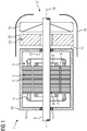
- FIG 1 shows initially a drive 1 according to the invention with a dynamo-electric rotary machine 2, which has a stator 3 which has a laminated core 5.
- a stator 3 which has a laminated core 5.
- grooves face an air gap 19 in which a winding system is arranged, which forms winding heads 4 on the end faces of the laminated core 5 of the stator 3.
- a laminated core 8 of a rotor 6 is non-rotatably connected to a shaft 9 and is in electromagnetic interaction with an energized winding system of the stator 3 and thus leads to a rotation of the shaft about an axis 18.
- the shaft 9 is held in two bearings, an AS bearing 11 and a BS bearing 12.
- the dynamoelectric rotary machine 2 is surrounded by a housing 10 which is delimited on the end faces by end plates 14.
- Axially spaced from the BS side there is an electronic add-on part 13 that contains at least components of a converter or actuator.
- the electronic add-on part 13 is stationary and not connected to the shaft 9 in a rotationally fixed manner.
- Axially connected to this is a fan 15, which is in turn connected to a shaft 9 in a rotationally fixed manner and generates a cooling air flow that is guided through a fan cover 16.
- the air flow is fed to the fan 15 via a suction opening 17.
- This fan 15 forms a basic cooling system for the drive 1.
- the heat is also transferred via the shaft 9, in particular from the rotor 6 of the dynamo-electric rotary machine 2 transported and fed to the fan 15, which functions as a heat dissipation element, which additionally generates a flow of cooling air when the dynamoelectric rotary machine 2 is in operation.
- the shaft 9 contains a material that is particularly thermally conductive.
- the heat transfer from the shaft 9 to the fan 15 is also designed to be thermally favorable by means of suitable materials.
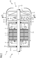
- the drive 1 now has - as in FIG FIG 2 shown - an internal fan 20 in the electronic attachment 13, which leads to an internal cooling circuit 22 within the closed electronic attachment 13.
- the internal fan 20 can either be controlled separately as an external fan depending on the temperature, or is coupled magnetically to the shaft 9 so that the electronic attachment 13 has a type of self-ventilation as soon as the shaft 9 rotates.
- the internal fan 20 thus takes the drive energy from the rotating field of the dynamo-electric rotary machine 2, in particular its harmonics.
- Corresponding antennas are arranged and shaped within the drive so that they absorb the energy of the electromagnetic radiation - in particular the harmonics of the air gap field. This absorbed energy is used to drive the internal fan 20.
- the antennas are arranged within the electronic attachment 13 and / or between the electronic attachment 13 and the dynamo-electric rotary machine 2, in particular in the area of the shaft 9.
- FIG 4 shows the arrangement of the internal fan 20 within the electronic add-on part 13 in a basic cross section.
- the shaft 9 is at a distance 26 from the walls of the housing arrangement 25.
- the housing assembly 25 is stationary.
- the internal fan 20 has a multiplicity of radially adjusted blades 27 which circulate an air flow within the housing arrangement of the electronic attachment part 13.
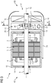
- the drive of the internal fan 20 can alternatively according to FIG 3 also take place via a magnetic coupling of magnets 23 positioned on the shaft 9 and magnets 23 arranged accordingly within the electronic attachment part 13.
- FIG 5 shows this arrangement in a basic cross section.
- the internal fan 20 is inside the housing arrangement 25 of the electronic add-on part 13.
- the shaft 9 is provided with a spacing 26 from the walls of the housing arrangement 25 and has magnets 23 on the outside in this axial section - opposite the housing arrangement 25.
- magnets 23 cause the inner fan 20 to rotate via magnets 28 in the hub of the inner fan 20.
- the housing arrangement 25 is stationary.
- the internal fan 20 has a multiplicity of radially adjusted blades 27 which circulate an air flow within the housing arrangement of the electronic attachment part 13.
- the internal fans 20 are rotatably mounted within the stationary attachment part 13.
- the actual temperature is determined using a temperature model and / or one or more temperature sensors in the dynamoelectric rotary machine 2 and / or the electronic attachment 13.
- the two fans 15, 20 can also maintain a redundant operation of the drive 1 at least temporarily if one of the two fans 15, 20 should fail.
- At least the internal fan 20 ensures that the heat from the power and control electronics generated within the housing arrangement 25 is evened out. This results in improved heat dissipation through the external cooling air flow 24, inter alia, at the housing arrangement 25. Be it at the radially outer edges, between the electronic attachment 13 and the bearing plate of the dynamoelectric machine 2, as well as between the radially inner edge of the housing arrangement 25 and the shaft 9.
- the drive 1 or the drive unit is fundamentally compact.
- the following features can be used individually or in any combination to design the drive 1 and put together.
- the compact drive 1 should include be cooled as best as possible.
- These components of the electronic add-on part 13 are arranged in a closed housing arrangement 25.
- the drive 1 and its respective sections / parts are cooled by one or more cooling units, which can be implemented as liquid cooling (cooling jacket on the housing arrangement 25 and / or on the housing 10 of the dynamoelectric rotary machine 2).
- Air cooling is preferably provided, the fan 15 of which is located on the side of the housing arrangement 25 facing away from the dynamoelectric rotary machine 2, so that there is an axial sequence of fan, housing arrangement 25 and dynamoelectric rotary machine 2.
- the fan 15 can also be constructed as a fan unit from one or more internal or external fans, which can also be at least partially integrated on or in a fan cover.
- a special design or recesses between the dynamo-electric rotary machine 2, in particular its end shield and the housing arrangement 25, create cooling channels that achieve a cooling venturi effect in the recesses due to a corresponding design and a main air flow.
- the housing arrangement 25 can also be funnel-shaped, the funnel having a cylindrical section and an axially tapering section that can be made in one piece from the same material, from several parts with different materials and from several parts with the same material.
- the cylindrical section and / or the axially tapering section has axially or quasi-radially extending ribs on its outside.
- the inside of the cylindrical section and / or of the axially tapering section is polygonal in order to be able to arrange actuator or converter components directly on the inside of the housing arrangement 25. This ensures a comparatively good thermal connection.
- the actuator or converter components can in particular also be arranged exclusively in the cylindrical section; in this case, the axially tapering section 26 acts as a heat capacity which has a thermally buffering effect.
- This section 26 is then designed as a solid material, which at the same time fulfills the function of a cover disk for the fan 15. This allows axially shorter Fan 15 can be used in order to obtain a more compact design of the drive.
- the internal fan 20 can either be controlled separately as an external fan depending on the temperature, or is magnetically coupled to the shaft 9, so that the electronic attachment 13 has a type of self-ventilation as soon as the shaft 9 rotates.
- the drive of the inner fan takes place via a magnetic coupling of magnets 23 positioned on the shaft 9 and correspondingly arranged magnets within the electronic attachment 13, for example on a hub of the inner fan 20.
- the internal fan 20 can also draw its drive energy from the rotating field of the dynamo-electric rotary machine 2, in particular its harmonics.
- the electrical drive energy of the internal fan 20 can also be taken directly from the actuator or converter components within the electronic attachment part 13.
- the internal fans 20 are rotatably mounted within the stationary attachment part 13.
- the actual temperature is determined using a temperature model and / or one or more temperature sensors in the dynamoelectric rotary machine 2 and / or the electronic attachment 13.
- the two fans 15, 20 can also maintain a redundant operation of the drive 1 at least temporarily if one of the two fans 15, 20 should fail.
- the drive 1 can also have a control unit that receives data from a wide variety of sensors, among others. Temperature sensors, vibration sensors, sound sensors. In this drive 1, the temperature sensors are arranged at the relevant installation locations. Temperature sensors for the outside air, for the electronic attachment 13, the power semiconductor in the electronic attachment 13, for the bearing (s) 11, 12, for the winding system and / or the end winding 4, for the interior of the machine 2, as well as for the Housing 10 and the environment provided.
- Attachment 13 are provided, are wired or wirelessly connected to a control unit which is arranged in the electronic attachment unit 13 or on the housing 10 of the machine 2, in particular in a terminal box or in the machine 2.
- Vibration sensors are attached to the shaft 9 and / or housing 10. Sound sensors are mainly used on sound-emitting sources such as Ribs or end shields 14 are provided. In addition, there are speed sensors for regulating the drive 1.
- the control unit regulates or controls, among other things the speed of the external fan (s) and / or the clock frequency of the converter. I.e. At particularly high outside temperatures and / or at a low speed of the shaft 9, the external fan is switched on depending on the temperature. The speed and thus the volume flow of the external fan 26 can also be controlled or regulated.
- the actual temperature preferably of the entire drive 1, is detected via one or more of the temperature sensors listed above.
- the drive 1 can be operated in an energy-efficient manner and maintenance intervals for the drive 1 and its components can also be better planned, e.g. Relubrication intervals for the bearings.
- the sensors are vibration sensors, temperature sensors, humidity sensors, etc.
- the sensors advantageously transmit their data to the control unit in a wired or wireless connection.
- the data is recorded either through direct contact or optically (e.g. infrared temperature measurement).
- the control units of different drives 1 can also be in contact via a cloud and exchange predefinable data from their drives.
- a thermally controllable or regulatable optimal operation of the drive 1 is thus guaranteed.
- certain settings of the clock frequency of the converter lead to lower losses in the converter, but increase the losses in the dynamoelectric machine 2.
- thermally favorable settings for the dynamoelectric machine 2 can put a greater thermal load on the converter.
- the converter can be adjusted accordingly via the control unit 27.
- the control unit 27 can also intervene in the cooling, for example by switching on or off one or more external fans of the drive 1 or by operating them at the corresponding speed.
Landscapes
- Engineering & Computer Science (AREA)
- Power Engineering (AREA)
- Physics & Mathematics (AREA)
- Thermal Sciences (AREA)
- Microelectronics & Electronic Packaging (AREA)
- Motor Or Generator Cooling System (AREA)
Priority Applications (2)
| Application Number | Priority Date | Filing Date | Title |
|---|---|---|---|
| EP19167301.1A EP3719970A1 (fr) | 2019-04-04 | 2019-04-04 | Unité d'entraînement à refroidissement interne d'un élément rapporté électronique |
| PCT/EP2020/057270 WO2020200763A1 (fr) | 2019-04-04 | 2020-03-17 | Unité d'entraînement dotée d'un refroidissement interne d'un ensemble électronique |
Applications Claiming Priority (1)
| Application Number | Priority Date | Filing Date | Title |
|---|---|---|---|
| EP19167301.1A EP3719970A1 (fr) | 2019-04-04 | 2019-04-04 | Unité d'entraînement à refroidissement interne d'un élément rapporté électronique |
Publications (1)
| Publication Number | Publication Date |
|---|---|
| EP3719970A1 true EP3719970A1 (fr) | 2020-10-07 |
Family
ID=66092179
Family Applications (1)
| Application Number | Title | Priority Date | Filing Date |
|---|---|---|---|
| EP19167301.1A Withdrawn EP3719970A1 (fr) | 2019-04-04 | 2019-04-04 | Unité d'entraînement à refroidissement interne d'un élément rapporté électronique |
Country Status (2)
| Country | Link |
|---|---|
| EP (1) | EP3719970A1 (fr) |
| WO (1) | WO2020200763A1 (fr) |
Families Citing this family (1)
| Publication number | Priority date | Publication date | Assignee | Title |
|---|---|---|---|---|
| DE102018216037B4 (de) * | 2018-09-20 | 2020-10-08 | Vitesco Technologies Germany Gmbh | Antriebseinrichtung für ein Kraftfahrzeug, insbesondere für einen Kraftwagen, sowie Kraftfahrzeug mit wenigstens einer solchen Antriebseinrichtung |
Citations (8)
| Publication number | Priority date | Publication date | Assignee | Title |
|---|---|---|---|---|
| DE3842588A1 (de) | 1988-12-17 | 1990-06-21 | Mulfingen Elektrobau Ebm | Kollektorloser aussenlaeufermotor mit halbleiter-kuehlungsanordnung |
| JPH07245888A (ja) * | 1994-03-04 | 1995-09-19 | Nippon Telegr & Teleph Corp <Ntt> | パワージェネレータ |
| DE19812729A1 (de) | 1998-03-24 | 1999-09-30 | Bosch Gmbh Robert | Elektromotor, insbesondere mit einem Lüfterrad zur Bildung eines Axial- oder Radiallüfters |
| US6141217A (en) * | 1997-10-03 | 2000-10-31 | Kabushiki Kaisha Toshiba | Enclosed control device |
| DE102004031399A1 (de) * | 2004-06-29 | 2006-02-16 | Siemens Ag | Umrichtermotor |
| JP2007151379A (ja) * | 2005-10-26 | 2007-06-14 | Toshiba Corp | 回転電機 |
| US20150130386A1 (en) * | 2012-11-01 | 2015-05-14 | Jared D. Zumstein | Methods and Apparatus for a Motor |
| CN204858754U (zh) * | 2015-08-03 | 2015-12-09 | 河南师范大学 | 一种电磁波电能转换装置 |
Family Cites Families (1)
| Publication number | Priority date | Publication date | Assignee | Title |
|---|---|---|---|---|
| AT513604B1 (de) * | 2013-02-25 | 2014-06-15 | Atb Motorenwerke Gmbh | Elektrische Maschine, insbesondere Motor |
-
2019
- 2019-04-04 EP EP19167301.1A patent/EP3719970A1/fr not_active Withdrawn
-
2020
- 2020-03-17 WO PCT/EP2020/057270 patent/WO2020200763A1/fr active Application Filing
Patent Citations (8)
| Publication number | Priority date | Publication date | Assignee | Title |
|---|---|---|---|---|
| DE3842588A1 (de) | 1988-12-17 | 1990-06-21 | Mulfingen Elektrobau Ebm | Kollektorloser aussenlaeufermotor mit halbleiter-kuehlungsanordnung |
| JPH07245888A (ja) * | 1994-03-04 | 1995-09-19 | Nippon Telegr & Teleph Corp <Ntt> | パワージェネレータ |
| US6141217A (en) * | 1997-10-03 | 2000-10-31 | Kabushiki Kaisha Toshiba | Enclosed control device |
| DE19812729A1 (de) | 1998-03-24 | 1999-09-30 | Bosch Gmbh Robert | Elektromotor, insbesondere mit einem Lüfterrad zur Bildung eines Axial- oder Radiallüfters |
| DE102004031399A1 (de) * | 2004-06-29 | 2006-02-16 | Siemens Ag | Umrichtermotor |
| JP2007151379A (ja) * | 2005-10-26 | 2007-06-14 | Toshiba Corp | 回転電機 |
| US20150130386A1 (en) * | 2012-11-01 | 2015-05-14 | Jared D. Zumstein | Methods and Apparatus for a Motor |
| CN204858754U (zh) * | 2015-08-03 | 2015-12-09 | 河南师范大学 | 一种电磁波电能转换装置 |
Also Published As
| Publication number | Publication date |
|---|---|
| WO2020200763A1 (fr) | 2020-10-08 |
Similar Documents
| Publication | Publication Date | Title |
|---|---|---|
| EP2979347B1 (fr) | Machine électrique pourvue d'un flasque | |
| DE112014002014B4 (de) | Hybridmodul für Kraftfahrzeug | |
| DE202010018108U1 (de) | Elektrische Antriebsanordnung | |
| WO2009033925A2 (fr) | Éolienne comprenant un système d'échangeur thermique | |
| EP3920385A1 (fr) | Machine à excitation électrique et agencement pour une machine à excitation électrique | |
| DE102016218741B4 (de) | Elektrische Maschine mit verbesserter Kühlung | |
| DE102011087602A1 (de) | Elektrische Maschine | |
| DE102008059171A1 (de) | Antriebsmotor mit integrierter Kühlung | |
| WO2019110275A1 (fr) | Machine électrique, en particulier pour véhicule | |
| DE102017109178A1 (de) | Drehende elektrische Maschine mit eingebautem Steuerungsgerät | |
| EP3719971A1 (fr) | Unité d'entraînement à gestion thermique | |
| EP3719970A1 (fr) | Unité d'entraînement à refroidissement interne d'un élément rapporté électronique | |
| EP1796249B1 (fr) | Machine électrique | |
| WO2020200762A1 (fr) | Unité d'entraînement dotée d'un refroidissement d'arbre | |
| EP3719972A1 (fr) | Unité d'entraînement d'une unité de refroidissement | |
| EP4010966B1 (fr) | Entraînement pourvu de boîtier de convertisseur segmenté | |
| EP3719969A1 (fr) | Unité d'entraînement dotée d'un système d'aération | |
| WO2013026693A2 (fr) | Machine électrique avec blindage amortisseur | |
| EP3719968A1 (fr) | Unité d'entraînement pourvue de logement pour une pièce rapportée électronique | |
| EP3719973A1 (fr) | Unité d'entraînement dotée d'une unité d'aérateur | |
| DE102009015770A1 (de) | Lüftervorrichtung | |
| EP2082636B1 (fr) | Unité d'entrainement et procédé pour faire fonctionner ladite unité d'entrainement | |
| WO2022152685A1 (fr) | Machine dynamo-électrique avec refroidissement du système à bagues collectrices | |
| EP3855602B1 (fr) | Machine électrique encapsulée | |
| WO2018100075A1 (fr) | Refroidissement à deux phases pour un système d'entraînement électrique |
Legal Events
| Date | Code | Title | Description |
|---|---|---|---|
| PUAI | Public reference made under article 153(3) epc to a published international application that has entered the european phase |
Free format text: ORIGINAL CODE: 0009012 |
|
| STAA | Information on the status of an ep patent application or granted ep patent |
Free format text: STATUS: THE APPLICATION HAS BEEN PUBLISHED |
|
| AK | Designated contracting states |
Kind code of ref document: A1 Designated state(s): AL AT BE BG CH CY CZ DE DK EE ES FI FR GB GR HR HU IE IS IT LI LT LU LV MC MK MT NL NO PL PT RO RS SE SI SK SM TR |
|
| AX | Request for extension of the european patent |
Extension state: BA ME |
|
| STAA | Information on the status of an ep patent application or granted ep patent |
Free format text: STATUS: THE APPLICATION IS DEEMED TO BE WITHDRAWN |
|
| 18D | Application deemed to be withdrawn |
Effective date: 20210408 |