EP3719373A1 - Verbindungsanordnung, vorzugsweise für eine fluidleitung eines fahrzeugs - Google Patents
Verbindungsanordnung, vorzugsweise für eine fluidleitung eines fahrzeugs Download PDFInfo
- Publication number
- EP3719373A1 EP3719373A1 EP20161299.1A EP20161299A EP3719373A1 EP 3719373 A1 EP3719373 A1 EP 3719373A1 EP 20161299 A EP20161299 A EP 20161299A EP 3719373 A1 EP3719373 A1 EP 3719373A1
- Authority
- EP
- European Patent Office
- Prior art keywords
- component
- connection arrangement
- sealing
- coupling
- arm
- Prior art date
- Legal status (The legal status is an assumption and is not a legal conclusion. Google has not performed a legal analysis and makes no representation as to the accuracy of the status listed.)
- Granted
Links
Images

Classifications
-
- F—MECHANICAL ENGINEERING; LIGHTING; HEATING; WEAPONS; BLASTING
- F16—ENGINEERING ELEMENTS AND UNITS; GENERAL MEASURES FOR PRODUCING AND MAINTAINING EFFECTIVE FUNCTIONING OF MACHINES OR INSTALLATIONS; THERMAL INSULATION IN GENERAL
- F16L—PIPES; JOINTS OR FITTINGS FOR PIPES; SUPPORTS FOR PIPES, CABLES OR PROTECTIVE TUBING; MEANS FOR THERMAL INSULATION IN GENERAL
- F16L25/00—Construction or details of pipe joints not provided for in, or of interest apart from, groups F16L13/00 - F16L23/00
- F16L25/06—Construction or details of pipe joints not provided for in, or of interest apart from, groups F16L13/00 - F16L23/00 comprising radial locking means
- F16L25/065—Construction or details of pipe joints not provided for in, or of interest apart from, groups F16L13/00 - F16L23/00 comprising radial locking means the locking means being actuated by radial screws
-
- F—MECHANICAL ENGINEERING; LIGHTING; HEATING; WEAPONS; BLASTING
- F16—ENGINEERING ELEMENTS AND UNITS; GENERAL MEASURES FOR PRODUCING AND MAINTAINING EFFECTIVE FUNCTIONING OF MACHINES OR INSTALLATIONS; THERMAL INSULATION IN GENERAL
- F16L—PIPES; JOINTS OR FITTINGS FOR PIPES; SUPPORTS FOR PIPES, CABLES OR PROTECTIVE TUBING; MEANS FOR THERMAL INSULATION IN GENERAL
- F16L37/00—Couplings of the quick-acting type
- F16L37/08—Couplings of the quick-acting type in which the connection between abutting or axially overlapping ends is maintained by locking members
- F16L37/12—Couplings of the quick-acting type in which the connection between abutting or axially overlapping ends is maintained by locking members using hooks, pawls, or other movable or insertable locking members
- F16L37/14—Joints secured by inserting between mating surfaces an element, e.g. a piece of wire, a pin, a chain
-
- F—MECHANICAL ENGINEERING; LIGHTING; HEATING; WEAPONS; BLASTING
- F16—ENGINEERING ELEMENTS AND UNITS; GENERAL MEASURES FOR PRODUCING AND MAINTAINING EFFECTIVE FUNCTIONING OF MACHINES OR INSTALLATIONS; THERMAL INSULATION IN GENERAL
- F16L—PIPES; JOINTS OR FITTINGS FOR PIPES; SUPPORTS FOR PIPES, CABLES OR PROTECTIVE TUBING; MEANS FOR THERMAL INSULATION IN GENERAL
- F16L2201/00—Special arrangements for pipe couplings
- F16L2201/10—Indicators for correct coupling
-
- F—MECHANICAL ENGINEERING; LIGHTING; HEATING; WEAPONS; BLASTING
- F16—ENGINEERING ELEMENTS AND UNITS; GENERAL MEASURES FOR PRODUCING AND MAINTAINING EFFECTIVE FUNCTIONING OF MACHINES OR INSTALLATIONS; THERMAL INSULATION IN GENERAL
- F16L—PIPES; JOINTS OR FITTINGS FOR PIPES; SUPPORTS FOR PIPES, CABLES OR PROTECTIVE TUBING; MEANS FOR THERMAL INSULATION IN GENERAL
- F16L2201/00—Special arrangements for pipe couplings
- F16L2201/30—Detecting leaks
Definitions
- the invention relates to a connection arrangement, preferably for a fluid line of a vehicle, with a first component and a second component to be coupled to it in a fluid-tight manner in a coupling position, a leakage opening being provided in the first component which closes by means of a sealant that simultaneously blocks the coupling position is closed.
- connection arrangements are for example from DE 10 2015 205 767 A1 known. They serve to connect fluid lines to one another in such a way that they can be tested to be fluid-tight. In their coupling position, the two components involved are securely coupled to one another in such a way that they are not separated from one another by vibrations. Furthermore, the tightness of the resulting fluid system required for operation is only guaranteed in the coupling position with the sealant used at the same time.
- a charge air duct is used in internal combustion engines to guide air to a turbocharger or compressor that is assigned to the internal combustion engine.
- a fluid valve by means of which air or gas-carrying lines of the charge air duct can be optionally closed.
- Such a fluid valve is off, for example DE 10 2009 024 697 A1 known.
- the invention is based on the object of creating a connection arrangement of the type mentioned at the outset which can be assembled in a particularly process-reliable manner and at the same time creates a permanently verifiable, fluid-tight connection between the components involved over the period of operation.
- connection arrangement preferably for a fluid line of a vehicle, with a first component and a second component to be coupled to it in a fluid-tight manner in a coupling position, a leakage opening being provided in the first component, which by means of a coupling position at the same time blocking sealant is to be closed.
- the sealing means is held in its sealing position blocking the coupling position by means of a screw bolt.
- the invention provides a connection arrangement in which, on the one hand, the components involved are secured against one another by means of a blocking sealant and, on the other hand, this sealant is additionally secured with regard to its position in a targeted manner by means of a screw bolt.
- the screw bolt can be monitored and checked for proper assembly.
- the sealant can be monitored and checked for its proper sealing position with the aid of a leak test.
- the connecting arrangement of this type creates an overall arrangement that is particularly reliable and at the same time particularly inexpensive to manufacture.
- Such an overall arrangement is particularly advantageous in particular for fresh air intake of a turbocharger on a cylinder head housing of an internal combustion engine.
- the charge air routing creates a line routing in particular or piping between the turbocharger, a crankshaft housing and a tank ventilation system of an associated internal combustion engine. It is therefore used in particular to discharge blow-by gases from the crankshaft housing and fuel vapors from the associated fuel tank.
- Such a line routing is also referred to as a compressor inlet bend.
- the sealing means according to the invention is preferably held on the first component by means of the screw bolt. When held in this way, the sealant is at the same time forced into its sealing position by the screw bolt and retained there.
- the sealing means is also advantageously to be inserted into the leakage opening in an insertion direction and the screw bolt is to be screwed in essentially parallel to the insertion direction.
- the screw bolt then acts in the direction in which the sealant is also to be forced into the first component for sealing at the leakage opening.
- the second component is preferably to be moved in a coupling direction to that of the first component and there to be coupled in a fluid-tight manner in its coupling position.
- the sealing means is preferably to be inserted into the leakage opening in an insertion direction on the first component, the insertion direction being designed to extend transversely to the coupling direction. With the cross to the coupling direction extending insertion direction, the first component is particularly effectively blocked by the sealing means transversely to its coupling direction.
- the first component is advantageously cylindrical, preferably circular in cross section. With such a component, in particular a block-shaped component, such as a housing for a valve or other hydraulic functional elements, can be produced.
- the second component is advantageously designed as a hollow cylinder, preferably circular in cross section. With such a component, in particular a tubular fluid line can be produced inexpensively.
- the sealing means is preferably designed with a sealing pin and an arm extending transversely thereto.
- the arm enables the sealing pin to be advantageously gripped manually and, in particular, also to be rotated. Such a rotary movement or pivoting movement is particularly advantageous when inserting and removing the sealant into or out of the leakage opening.
- the screw bolt is advantageous for holding the sealant in its sealing position blocking the coupling position to be screwed through the arm.
- the screw bolt then engages the arm in such a way that the sealing means is pushed in the direction of the first component and at the same time is also fixed in its rotational position.
- a guide sleeve through which the screw bolt passes is preferably provided on the arm, by means of which a movement of the arm in different directions is to be limited.
- the sealing means can be preassembled together with the arm on the first component and then moved, guided, into its sealing end position.
- the arm, together with the sealing means should preferably first be pivoted and then inserted into the leakage opening in the insertion direction.
- the guide sleeve is preferably circular in cross-section and designed as a swivel sleeve, and in the linear direction as a sliding sleeve.
- the rotational or pivoting movement of the guide sleeve is preferably limited by means of two end stops there and the sliding movement is preferably limited by means of a longitudinal groove there.
- the second component is preferably also designed with a blocking opening into which the sealing means is to be moved into its sealing position blocking the coupling position.
- the blocking opening creates a visually easily recognizable marking which, during assembly, only needs to be aligned with the leakage opening in order to establish the correct coupling position of the two components.
- the invention is also directed to a use of such a connection arrangement according to the invention specifically for fluid-tight coupling of a second component to a first component of a fluid line of a vehicle, preferably to a charge air duct of a turbocharger, and to a subsequent checking of the connection arrangement for proper coupling by means of a vehicle's own leak test.
- connection arrangement 10 of a charge air duct, not shown further illustrated.
- the connection arrangement 10 forms part of a fluid line 12 of the charge air duct, which passes through the connection arrangement 10 and is illustrated here with the aid of two arrows.
- the connection arrangement 10 comprises a first component 14, which is essentially cylindrical and has a circular cross-section as a housing.
- a first component 14 which is essentially cylindrical and has a circular cross-section as a housing.
- an interior space 16 which is open on one side and is delimited on its axially opposite side by means of an end wall 18.
- an end wall 18 facing away from the interior 16, there is a front, central connection 20.
- the interior 16 is delimited radially on the outside by an annular wall 22.
- the connecting arrangement 10 comprises a second component 28, which in the present case is designed as a tube, essentially hollow-cylindrical and with a circular cross-section.
- the second component 28, which is tubular in this way, has an outer jacket surface 30, on whose end region facing the first component 14 a circular blocking opening 32 penetrating the jacket surface 30 is formed.
- a recess 34 likewise penetrating the jacket surface 30 is formed in the jacket surface 30, which recess extends to the front edge of the jacket surface 30.
- the second component 28 is to be pushed onto the first component 14 in a coupling direction 36, whereby its lateral surface 30 is pushed over the ring wall 22 in such a way that the blocking opening 32 comes to lie congruent with the leakage opening 24.
- the two components 14 and 28 are then in the so-called coupling position.
- a sealing means 38 is also provided on the connecting arrangement 10, which is designed with a cylindrical sealing pin 40 on which a sealing ring 42 is arranged. At one end region of the cylindrical sealing pin 40, a flat arm 44 projects radially from the latter, which arm has an underside 46 of the arm and in which an arm opening 48 penetrating the arm 44 is located at the end region facing away from the sealing pin 40.
- the sealing pin 40 In the coupling position of the first component 14 and the second component 28, the sealing pin 40 is to be inserted in an insertion direction 50 through the blocking opening 32 into the leakage opening 24 until the sealing ring 42 rests fluid-tight on the sealing seat 26.
- the sealing pin 40 can be pressed in by means of the arm 44 and also rotated.
- a projection 60 with a flat projection top side 62 which comes to lie in the coupling position in the recess 34 and thus a positional and, in particular, rotation lock for the first Component 14 represents on the second component 28.
- a screw-in opening 64 with an internal thread 66 is formed in the extension 60.
- the screw bolt 52 In the coupling position, the screw bolt 52 is to be screwed into the screw-in opening 64 in a screw-in direction 68.
- the screw-in direction 68 extends parallel to the plug-in direction 50.
- the screw bolt 52 is screwed in until its bolt head 58 comes to rest on the arm 44 and presses this together with its lower arm 46 against the upper side 62.
- the sealing means 38 seals the leakage opening 24 in a fluid-tight manner and at the same time holds the blocking opening 32 in a stationary manner. In this way, it can also be ensured during the entire operating time of the associated charge air duct that a proper and tight connection between the two components 14 and 28 is created.
- This connection can also be monitored by means of a vehicle's own leak test, a so-called on-board diagnostic function (OBD).
- OBD on-board diagnostic function
- FIGs. 3 to 5 show a further exemplary embodiment of a connection arrangement 10 of a charge air duct in which the recess 34 on the second component 28 is made longer in the coupling direction 36.
- an angled plug connector 70 protruding from the first component 14 is to be introduced into this oblong recess 34.
- the second component 28 is fixed in terms of its position relative to the first component 14 after the coupling.
- the blocking opening 32 of the second component 28 is positioned precisely above the leakage opening 24 of the first component 14.
- approach 60 is in the embodiment according to Figs. 3 to 5 When viewed in the coupling direction 36, it is arranged further back on the first component 14 and thus outside the second component 28.
- the extension 60 there is also provided with a screw-in opening 64 for screwing in a screw bolt 52.
- a sealing means 38 with an arm 44 and an arm opening 48 is also provided on this extension 60.
- the arm opening 48 of this exemplary embodiment is, however, surrounded by a guide sleeve 72 through which the screw bolt 52 is to be screwed.
- the approach 60 according to the Figures 4 to 5 is also designed higher and its top side 62 protrudes into the guide sleeve 72.
- a first end stop 74 and a second end stop 76 are formed on the guide sleeve 72 on its end region facing the first component 14. Viewed in the screwing-in direction 68, the guide sleeve 72 is penetrated by a longitudinal groove 78.
- the end of the longitudinal web 80 facing away from the first component 14 is to be inserted into the longitudinal groove 78 by means of the sealing means 38 so that the longitudinal web 80 completely enters the longitudinal groove 78, while at the same time the sealing means 38 according to the parallel Insertion direction 50 is guided into the leakage opening 24 and to the sealing seat 26 there (see Fig. 5 ).
Landscapes
- Engineering & Computer Science (AREA)
- General Engineering & Computer Science (AREA)
- Mechanical Engineering (AREA)
- Gasket Seals (AREA)
Abstract
Description
- Die Erfindung betrifft eine Verbindungsanordnung, vorzugsweise für eine Fluidleitung eines Fahrzeugs, mit einem ersten Bauteil und einem daran in einer Koppelstellung fluiddicht anzukoppelnden, zweiten Bauteil, wobei in dem ersten Bauteil eine Leckage-Öffnung vorgesehen ist, die mittels eines zugleich die Koppelstellung blockierenden Dichtmittels zu verschließen ist.
- Derartige Verbindungsanordnungen sind beispielsweise aus
DE 10 2015 205 767 A1 bekannt. Sie dienen dazu, Fluidleitungen miteinander derart zu verbinden, dass diese prüfbar fluiddicht sind. In ihrer Koppelstellung sind die beiden beteiligten Bauteile derart sicher miteinander gekoppelt, dass sie auch durch Vibrationen nicht voneinander getrennt werden. Ferner ist nur in der Koppelstellung mit zugleich eingesetztem Dichtmittel die für den Betrieb erforderliche Dichtigkeit des resultierenden Fluidsystems gewährleistet. - Bei komplexen Fluidsystemen sind zugleich Montagefehler weitestgehend zu vermeiden. Darüber hinaus besteht für die Montage solcher Fluidsysteme insbesondere im Kraftfahrzeugbereich ein besonders hoher Druck zu Kosteneinsparungen.
- Eine Ladeluftführung dient bei Brennkraftmaschinen dazu, um Luft zu einem Turbolader bzw. Verdichter zu führen, der der Brennkraftmaschine zugeordnet ist. Bei derartigen Ladeluftführungen ist es bekannt ein Fluidventil einzusetzen, mittels dessen luft- bzw. gasführende Leitungen der Ladeluftführung wahlweise zu verschließen ist. Ein solches Fluidventil ist beispielsweise aus
DE 10 2009 024 697 A1 bekannt. - Der Erfindung liegt die Aufgabe zugrunde, eine Verbindungsanordnung der eingangs genannten Art zu schaffen, die besonders prozesssicher zu montieren ist und zugleich über die Betriebsdauer hinweg eine dauerhaft nachprüfbar fluiddichte Verbindung zwischen den beteiligten Bauteilen herstellt.
- Die Aufgabe ist erfindungsgemäß mit einer Verbindungsanordnung gelöst, vorzugsweise für eine Fluidleitung eines Fahrzeugs, mit einem ersten Bauteil und einem daran in einer Koppelstellung fluiddicht anzukoppelnden, zweiten Bauteil, wobei in dem ersten Bauteil eine Leckage-Öffnung vorgesehen ist, die mittels eines zugleich die Koppelstellung blockierenden Dichtmittels zu verschließen ist. Dabei ist gemäß der Erfindung das Dichtmittel in seiner die Koppelstellung blockierenden Dichtlage mittels eines Schraubbolzens gehalten.
- Die Erfindung stellt eine Verbindungsanordnung bereit, bei der zum einen die beteiligten Bauteile mittels eines blockierenden Dichtmittels gegeneinander gesichert sind und zum anderen dieses Dichtmittel zusätzlich gezielt mittels eines Schraubbolzens hinsichtlich seiner Lage gesichert ist. Dabei kann während der Montage der Verbindungsanordnung der Schraubbolzen auf ordnungsgemäße Montage überwacht und geprüft werden. Nachfolgend kann während des Betriebs der Verbindungsanordnung das Dichtmittel mit Hilfe einer Dichtheitsprüfung auf seine ordnungsgemäße Dichtlage überwacht und geprüft werden. Die derartige Verbindungsanordnung schafft eine besonders betriebssichere und zugleich besonders kostengünstig herzustellende Gesamtanordnung.
- Eine solche Gesamtanordnung ist insbesondere für eine Frischluftansaugung eines Turboladers an einem Zylinderkopfgehäuse einer Brennkraftmaschine besonders vorteilhaft. Die Ladeluftführung schafft dabei insbesondere eine Leitungsführung bzw. Verrohrung zwischen dem Turbolader, einem Kurbelwellengehäuse sowie einem Tankentlüftungssystem einer zugeordneten Brennkraftmaschine. Sie dient damit insbesondere zum Abführen von Blow-By-Gasen aus dem Kurbelwellengehäuse sowie von Kraftstoffdämpfen aus dem zugehörigen Kraftstofftank. Eine solche Leitungsführung wird auch als Verdichter-Eintrittsbogen bezeichnet.
- Bei Kraftfahrzeugen ist es bekannt, eine Dichtigkeit von Fluidleitungssystemen mittels einer so genannten On-Board-Diagnose-Funktion im Fahrzeug (OBD) durchzuführen. Dabei wird ein definiertes Vakuum bzw. einen definierten Überdruck in dem Fluidleitungssystem aufgebaut. Eine Undichtigkeit kann somit erkannt werden, wenn das definierte Vakuum (durch Ziehen von sogenannter Falschluft) bzw. der definierte Überdruck (aufgrund von unerwünschtem Entweichen von Fluid) nicht in einer vorgegebenen Zeit erreicht werden kann. Die derartige Prüffunktion kann erfindungsgemäß vorteilhaft genutzt werden, um die ordnungsgemäße Montage der Verbindungsanordnung gemäß der Erfindung auch über deren Lebensdauer hinweg sicherzustellen.
- Das erfindungsgemäße Dichtmittel ist vorzugsweise mittels des Schraubbolzens an dem ersten Bauteil gehalten. Derart gehaltert ist das Dichtmittel von dem Schraubbolzen zugleich in seine Dichtlage gedrängt und dort zurückgehalten.
- Das Dichtmittel ist ferner vorteilhaft in einer Einsteckrichtung in die Leckage-Öffnung einzustecken und der Schraubbolzen ist dabei im Wesentlichen parallel zu der Einsteckrichtung einzuschrauben. Der Schraubbolzen wirkt dann in jene Richtung, in die auch das Dichtmittel zum Abdichten an der Leckage-Öffnung in das erste Bauteil zu drängen ist.
- Das zweite Bauteil ist vorzugsweise in einer Koppelrichtung an das das erste Bauteil zu bewegen und dort in seiner Koppelstellung fluiddicht anzukoppeln. Ferner ist bevorzugt an dem ersten Bauteil das Dichtmittel in einer Einsteckrichtung in die Leckage-Öffnung einzustecken, wobei die Einsteckrichtung sich quer zu der Koppelrichtung erstreckend gestaltet ist. Mit der sich quer zur Koppelrichtung erstreckenden Einsteckrichtung ist das erste Bauteil von dem Dichtmittel besonders effektiv quer zu seiner Koppelrichtung gesperrt.
- Das erste Bauteil ist vorteilhaft zylindrisch, vorzugsweise im Querschnitt kreisförmig gestaltet. Mit einem solchen Bauteil ist insbesondere ein blockförmiges Bauteil, wie etwa ein Gehäuse für ein Ventil oder andere hydraulische Funktionselemente herzustellen. Das zweite Bauteil ist vorteilhaft hohlzylindrisch, vorzugsweise im Querschnitt kreisringförmig gestaltet. Mit einem solchen Bauteil ist insbesondere eine rohrförmige Fluidleitung kostengünstig herzustellen.
- Das Dichtmittel ist vorzugsweise mit einem Dichtstift und einem sich quer dazu erstreckenden Arm gestaltet. Der Arm ermöglicht es, dass der Dichtstift vorteilhaft manuell gegriffen und insbesondere auch gedreht werden kann. Eine solche Drehbewegung bzw. Schwenkbewegung ist besonders beim Einführen und auch beim Entfernen des Dichtmittels in bzw. aus der Leckage-Öffnung von Vorteil.
- Der Schraubbolzen ist vorteilhaft zum Halten des Dichtmittels in dessen die Koppelstellung blockierenden Dichtlage den Arm durchsetzend einzuschrauben. Der Schraubbolzen greift dann derart an dem Arm an, dass das Dichtmittel in Richtung zum ersten Bauteil gedrängt und zugleich auch in seiner Drehlage festgelegt ist.
- An dem Arm ist vorzugsweise ferner eine vom Schraubbolzen durchsetzte Führungshülse vorgesehen, mittels der eine Bewegung des Arms in verschiedene Richtungen zu begrenzen ist. Mittels der Führungshülse kann beim Montieren der erfindungsgemäßen Verbindungsanordnung das Dichtmittel zusammen mit dem Arm an dem ersten Bauteil vormontiert und dann geführt in seine dichtende Endstellung bewegt werden. Bei dieser geführten Bewegung ist der Arm zusammen mit dem Dichtmittel vorzugsweise zunächst zu schwenken und dann in der Einsteckrichtung in die Leckage-Öffnung einzustecken. Die Führungshülse ist dazu vorzugsweise zum einen im Querschnitt kreisförmig und als eine Schwenkhülse gestaltet, und zum anderen in linearer Richtung als eine Schiebehülse gestaltet. Dabei ist die Dreh- bzw. Schwenkbewegung der Führungshülse vorzugsweise mittels zweier dortiger Endanschläge und die Schiebebewegung vorzugsweise mittels einer dortigen Längsnut begrenzt.
- Das zweite Bauteil ist erfindungsgemäß bevorzugt ferner mit einer Blockier-Öffnung gestaltet, in die hinein das Dichtmittel in dessen die Koppelstellung blockierende Dichtlage zu bewegen ist. Die Blockier-Öffnung schafft eine optisch auch automatisiert gut erkennbare Markierung, die beim Montieren lediglich mit der Leckage-Öffnung auszurichten ist, um dadurch die lagegerechte Koppelstellung der beiden Bauteile herzustellen.
- Gemäß oben genannter Vorteile ist die Erfindung entsprechend ferner auf eine Verwendung einer derartigen erfindungsgemäßen Verbindungsanordnung speziell zum fluiddichten Ankoppeln eines zweiten Bauteils an einem ersten Bauteil einer Fluidleitung eines Fahrzeugs gerichtet, vorzugsweise an einer Ladeluftführung eines Turboladers, und auf ein nachfolgendes Prüfen der Verbindungsanordnung auf ordnungsgemäße Ankopplung mittels einer fahrzeugeigenen Dichtheitsprüfung.
- Nachfolgend wird ein Ausführungsbeispiel der erfindungsgemäßen Lösung anhand der beigefügten, schematischen Zeichnungen näher erläutert. Es zeigt:
-
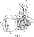
Fig. 1 eine perspektivische Ansicht eines ersten Ausführungsbeispiels einer erfindungsgemäßen Verbindungsanordnung einer Ladeluftführung in nicht gekoppelter Stellung, -
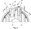
Fig. 2 den Schnitt II - II gemäßFig. 1 in Koppelstellung, -
Fig. 3 eine perspektivische Ansicht eines zweiten Ausführungsbeispiels einer erfindungsgemäßen Verbindungsanordnung einer Ladeluftführung in nicht gekoppelter Stellung, -
Fig. 4 die Ansicht IV gemäßFig. 3 in gekoppelter, aber nicht blockierter Stellung und -
Fig. 5 die Ansicht IV in gekoppelter sowie blockierter Stellung. - In
Fig. 1 undFig. 2 ist ein Teil einer Verbindungsanordnung 10 einer weiter nicht dargestellten Ladeluftführung veranschaulicht. Die Verbindungsanordnung 10 bildet einen Teil einer Fluidleitung 12 der Ladeluftführung, die durch die Verbindungsanordnung 10 hindurchführt und hier mit Hilfe zweier Pfeile veranschaulicht ist. - Die Verbindungsanordnung 10 umfasst ein erstes Bauteil 14, das im Wesentlichen zylindrisch und im Querschnitt kreisförmig als Gehäuse ausgebildet ist. In dem Bauteil 14 befindet sich ein Innenraum 16, der an einer Seite offen und an seiner axial gegenüberliegenden Seite mittels einer Stirnwand 18 begrenzt ist. An der Stirnwand 18 befindet sich vom Innenraum 16 abgewandt ein stirnseitiger, zentraler Anschluss 20. Radial außen ist der Innenraum 16 von einer Ringwand 22 begrenzt.
- In der Ringwand 22 befindet sich an deren zur Stirnwand 18 gewandtem Endbereich eine kreisrunde Leckage-Öffnung 24, in deren Innenseite ein Dichtsitz 26 ausgebildet ist.
- Ferner umfasst die Verbindungsanordnung 10 ein zweites Bauteil 28, das vorliegend als Rohr im Wesentlichen hohlzylindrisch und im Querschnitt kreisringförmig gestaltet ist. Das derart rohrförmige, zweite Bauteil 28 weist eine äußere Mantelfläche 30 auf, an deren zum ersten Bauteil 14 gewandten Endbereich eine kreisrunde und die Mantelfläche 30 durchsetzende Blockier-Öffnung 32 ausgebildet ist. Neben der Blocker-Öffnung 32 ist in der Mantelfläche 30 ferner eine die Mantelfläche 30 ebenfalls durchsetzende Aussparung 34 ausgebildet, die sich bis an den stirnseitigen Rand der Mantelfläche 30 erstreckt.
- Das zweite Bauteil 28 ist in eine Koppelrichtung 36 auf das erste Bauteil 14 aufzuschieben, wodurch dessen Mantelfläche 30 derart über die Ringwand 22 geschoben wird, dass die Blockier-Öffnung 32 deckungsgleich mit der Leckage-Öffnung 24 zu liegen kommt. Die beiden Bauteile 14 und 28 befinden sich dann in der so genannten Koppelstellung.
- An der Verbindungsanordnung 10 ist ferner ein Dichtmittel 38 vorgesehen, das mit einem zylindrischen Dichtstift 40 gestaltet ist, auf dem ein Dichtring 42 angeordnet ist. An einem Endbereich des zylindrischen Dichtstifts 40 steht von diesem radial ein flacher Arm 44 ab, der eine Arm-Unterseite 46 aufweist und in dem sich am vom Dichtstift 40 abgewandten Endbereich eine den Arm 44 durchsetzende Arm-Öffnung 48 befindet.
- Der Dichtstift 40 ist in der Koppelstellung des ersten Bauteils 14 und des zweiten Bauteils 28 in einer Einsteckrichtung 50 durch die Blockier-Öffnung 32 hindurch in die Leckage-Öffnung 24 einzustecken, bis der Dichtring 42 am Dichtsitz 26 fluiddicht zum Anliegen kommt. Dabei kann der Dichtstift 40 mittels des Arms 44 eingepresst und auch gedreht werden.
- Schließlich befindet sich an der Verbindungsanordnung 10 noch ein Schraubbolzen 52, der mit einem Bolzenschaft 54 mit Schaftgewinde 56 und einem Bolzenkopf 58 versehen ist.
- An dem ersten Bauteil 14 befindet sich in Umfangsrichtung neben der Leckage-Öffnung 24 ein Ansatz 60 mit einer ebenen Ansatz-Oberseite 62, der in der Koppelstellung in der Aussparung 34 zu liegen kommt und so eine Lage- und insbesondere Verdreh-Sicherung für das erste Bauteil 14 auf dem zweiten Bauteil 28 darstellt. In dem Ansatz 60 ist eine Einschraub-Öffnung 64 mit einem Innengewinde 66 ausgebildet.
- Der Schraubbolzen 52 ist in der Koppelstellung in die Einschraub-Öffnung 64 in eine Einschraubrichtung 68 einzuschrauben. Die Einschraubrichtung 68 erstreckt sich dabei parallel zu der Einsteckrichtung 50. Der Schraubbolzen 52 ist so weit einzuschrauben, bis sein Bolzenkopf 58 am Arm 44 zum Anliegen kommt und diesen zusammen mit seiner Arm-Unterseite 46 gegen die Ansatz-Oberseite 62 drängt. In dieser eingeschraubten Lage des Schraubbolzens 52 ist das Dichtmittel 38 die Leckage-Öffnung 24 fluiddicht abdichtend und zugleich die Blockier-Öffnung 32 sperrend ortsfest gehalten. Auf diese Weise kann auch während der gesamten Betriebsdauer der zugehörigen Ladeluftführung sichergestellt werden, dass eine ordnungsgemäße und dichte Verbindung zwischen den beiden Bauteilen 14 und 28 geschaffen ist. Diese Verbindung kann zugleich mittels einer fahrzeugeigenen Dichtheitsprüfung, einer so genannten On-Board-Diagnose-Funktion (OBD) überwacht werden. Sobald es aufgrund einer Lageänderung des Dichtmittels 38 an der Dichtstelle von Dichtring 42 zu Dichtsitz 26 auch nur zu einer kleinen Undichtigkeit kommen sollte, würde diese von der Dichtheitsprüfung sofort erkannt werden.
- Die
Fig. 3 bis 5 zeigen ein weiteres Ausführungsbeispiel einer Verbindungsanordnung 10 einer Ladeluftführung, bei dem die Aussparung 34 an dem zweiten Bauteil 28 in Koppelrichtung 36 länger ausgebildet ist. In diese derart längliche Aussparung 34 ist beim Koppeln der beiden Bauteile 14 und 28 ein gewinkelter und vom ersten Bauteil 14 abstehender Steckeranschluss 70 einzuführen. Mit der derartigen Führung des Steckeranschlusses 70 in der Aussparung 34 ist nach dem Koppeln das zweite Bauteil 28 hinsichtlich seiner relativen Lage zum ersten Bauteil 14 festgelegt. Zugleich ist die Blockier-Öffnung 32 des zweiten Bauteils 28 lagegenau über der Leckage-Öffnung 24 des ersten Bauteils 14 positioniert. - Der bei dem Ausführungsbeispiel gemäß
Fig. 1 und2 vorgesehene Ansatz 60 ist bei dem Ausführungsbeispiel gemäßFig. 3 bis 5 in Koppelrichtung 36 betrachtet weiter hinten an dem ersten Bauteil 14 und damit außerhalb des zweiten Bauteils 28 angeordnet. Der dortige Ansatz 60 ist ebenfalls mit einer Einschraub-Öffnung 64 zum Einschrauben eines Schraubbolzens 52 versehen. - Ferner ist auch an diesem Ansatz 60 ein Dichtmittel 38 mit einem Arm 44 und einer Arm-Öffnung 48 vorgesehen. Die Arm-Öffnung 48 dieses Ausführungsbeispiels ist allerdings mit einer Führungshülse 72 umgeben, durch die hindurch der Schraubbolzen 52 einzuschrauben ist. Der Ansatz 60 gemäß den
Fig. 4 bis 5 ist zudem höher gestaltet und seine Ansatz-Oberseite 62 ragt bis in die Führungshülse 72 hinein. - Darüber hinaus sind an der Führungshülse 72 an deren dem ersten Bauteil 14 zugewandten Endbereich ein erster Endanschlag 74 sowie ein zweiter Endanschlag 76 ausgebildet. In Einschraubrichtung 68 betrachtet ist die Führungshülse 72 von einer Längsnut 78 durchsetzt.
- Als Gegenstück zu diesen Endanschlägen 74 und 76 sowie der Längsnut 78 befindet sich an dem Ansatz 60 in Einschraubrichtung 68 ein passgenauer Längssteg 80. Das vom ersten Bauteil 14 abgewandte Ende dieses Längsstegs 80 wirkt mit den beiden Endanschlägen 74 und 76 derart zusammen, dass eine Dreh- bzw. Schwenkbewegung der Führungshülse 72 zusammen mit dem Arm 44 und dem Dichtmittel 38 über einen vordefinierten Winkelbereich möglich, dass darüber hinaus aber eine solche Dreh- bzw. Schwenkbewegung der Führungshülse 72 begrenzt bzw. nicht möglich ist (siehe
Fig. 4 ). - Ferner ist das vom ersten Bauteil 14 abgewandte Endes des Längsstegs 80 beim Blockieren der beiden Bauteile 14 und 28 mittels des Dichtmittels 38 derart in die Längsnut 78 einzuführen, dass der Längssteg 80 vollständig in die Längsnut 78 eintritt, während zugleich das Dichtmittel 38 gemäß der parallelen Einsteckrichtung 50 in die Leckage-Öffnung 24 und an den dortigen Dichtsitz 26 geführt wird (siehe
Fig. 5 ). -
- 10
- Verbindungsanordnung einer Ladeluftführung
- 12
- Fluidleitung
- 14
- erstes Bauteil, zylindrisch, im Querschnitt kreisförmig, als Gehäuse
- 16
- Innenraum
- 18
- Stirnwand
- 20
- stirnseitiger Anschluss
- 22
- Ringwand
- 24
- Leckage-Öffnung
- 26
- Dichtsitz
- 28
- zweites Bauteil, hohlzylindrisch, im Querschnitt kreisringförmig, als Rohr
- 30
- äußere Mantelfläche
- 32
- Blockier-Öffnung
- 34
- Aussparung
- 36
- Koppelrichtung
- 38
- Dichtmittel
- 40
- Dichtstift
- 42
- Dichtring
- 44
- Arm
- 46
- Arm-Unterseite
- 48
- Arm-Öffnung
- 50
- Einsteckrichtung
- 52
- Schraubbolzen
- 54
- Bolzenschaft
- 56
- Schaftgewinde
- 58
- Bolzenkopf
- 60
- Ansatz
- 62
- Ansatz-Oberseite
- 64
- Einschraub-Öffnung
- 66
- Innengewinde
- 68
- Einschraubrichtung
- 70
- Steckeranschluss
- 72
- Führungshülse
- 74
- Endanschlag
- 76
- Endanschlag
- 78
- Längsnut
- 80
- Längssteg
Claims (10)
- Verbindungsanordnung (10), vorzugsweise für eine Fluidleitung (12) eines Fahrzeugs, mit einem ersten Bauteil (14) und einem daran in einer Koppelstellung fluiddicht anzukoppelnden, zweiten Bauteil (28), wobei in dem ersten Bauteil (14) eine Leckage-Öffnung (24) vorgesehen ist, die mittels eines zugleich die Koppelstellung blockierenden Dichtmittels (38) zu verschließen ist,
dadurch gekennzeichnet, dass das Dichtmittel (38) in seiner die Koppelstellung blockierenden Dichtlage mittels eines Schraubbolzens (52) gehalten ist. - Verbindungsanordnung nach Anspruch 1,
dadurch gekennzeichnet, dass das Dichtmittel (38) mittels des Schraubbolzens (52) an dem ersten Bauteil (14) gehalten ist. - Verbindungsanordnung nach Anspruch 1 oder 2,
dadurch gekennzeichnet, dass das Dichtmittel (38) in einer Einsteckrichtung (50) in die Leckage-Öffnung (24) einzustecken ist und der Schraubbolzen (52) im Wesentlichen parallel zu der Einsteckrichtung (50) einzuschrauben ist. - Verbindungsanordnung nach einem der Ansprüche 1 bis 3,
dadurch gekennzeichnet, dass das zweiten Bauteil (28) in einer Koppelrichtung (36) an das erste Bauteil (14) zu bewegen und dort in seiner Koppelstellung fluiddicht anzukoppeln ist und an dem ersten Bauteil (14) das Dichtmittel (38) in einer Einsteckrichtung (50) in die Leckage-Öffnung (24) einzustecken ist, wobei die Einsteckrichtung (50) sich quer zu der Koppelrichtung (36) erstreckend gestaltet ist. - Verbindungsanordnung nach einem der Ansprüche 1 bis 4,
dadurch gekennzeichnet, dass erste Bauteil (14) zylindrisch, vorzugsweise im Querschnitt kreisförmig gestaltet ist, und dass das zweite Bauteil (28) hohlzylindrisch, vorzugsweise im Querschnitt kreisringförmig gestaltet ist. - Verbindungsanordnung nach einem der Ansprüche 1 bis 5,
dadurch gekennzeichnet, dass das Dichtmittel (38) mit einem Dichtstift (40) und einem sich quer dazu erstreckenden Arm (44) gestaltet ist. - Verbindungsanordnung nach Anspruch 6,
dadurch gekennzeichnet, dass der Schraubbolzen (52) zum Halten des Dichtmittels (38) in dessen die Koppelstellung blockierenden Dichtlage den Arm (44) durchsetzend einzuschrauben ist. - Verbindungsanordnung nach Anspruch 7,
dadurch gekennzeichnet, dass an dem Arm (44) eine vom Schraubbolzen (52) durchsetzte Führungshülse vorgesehen ist, mittels der eine Bewegung des Arms (44) zu begrenzen ist. - Verbindungsanordnung nach einem der Ansprüche 1 bis 8,
dadurch gekennzeichnet, dass das zweite Bauteil (28) mit einer Blockier-Öffnung (32) gestaltet ist, in die hinein das Dichtmittel (38) in dessen die Koppelstellung blockierende Dichtlage zu bewegen ist. - Verwendung einer Verbindungsanordnung (10) nach einem der Ansprüche 1 bis 9 zum fluiddichten Ankoppeln eines zweiten Bauteils (28) an einem ersten Bauteil (14) einer Fluidleitung (12) eines Fahrzeugs, vorzugsweise an einer Ladeluftführung eines Turboladers, und Prüfen der Verbindungsanordnung (10) auf ordnungsgemäße Ankopplung mittels einer fahrzeugeigenen Dichtheitsprüfung.
Applications Claiming Priority (1)
| Application Number | Priority Date | Filing Date | Title |
|---|---|---|---|
| DE102019108744.9A DE102019108744A1 (de) | 2019-04-03 | 2019-04-03 | Verbindungsanordnung, vorzugsweise für eine Fluidleitung eines Fahrzeugs |
Publications (2)
| Publication Number | Publication Date |
|---|---|
| EP3719373A1 true EP3719373A1 (de) | 2020-10-07 |
| EP3719373B1 EP3719373B1 (de) | 2023-04-12 |
Family
ID=69779895
Family Applications (1)
| Application Number | Title | Priority Date | Filing Date |
|---|---|---|---|
| EP20161299.1A Active EP3719373B1 (de) | 2019-04-03 | 2020-03-05 | Verbindungsanordnung, vorzugsweise für eine fluidleitung eines fahrzeugs |
Country Status (2)
| Country | Link |
|---|---|
| EP (1) | EP3719373B1 (de) |
| DE (1) | DE102019108744A1 (de) |
Citations (5)
| Publication number | Priority date | Publication date | Assignee | Title |
|---|---|---|---|---|
| WO2009103995A1 (en) * | 2008-02-23 | 2009-08-27 | Pipejoin Technologies Incorporated | Coupling |
| DE102009024697A1 (de) | 2009-06-12 | 2010-12-16 | Aft Inh. Dirk Kramer E.K. | Vorrichtung zum Einspeisen von flüchtigen Kraftstoffbestandteilen in ein Ansaugsystem einer Brennkraftmaschine |
| EP2613073A1 (de) * | 2011-01-13 | 2013-07-10 | Kobayashi, Kazumi | Verbindungsstruktur für druckrohrleitungen |
| DE102015205767A1 (de) | 2015-03-31 | 2016-10-06 | Fränkische Industrial Pipes GmbH & Co. KG | Verbindungsanordnung mit Diagnosefunktion |
| DE102017108201B3 (de) * | 2017-04-18 | 2017-12-21 | Schaeffler Technologies AG & Co. KG | Verbindungsanordnung zur Verbindung einer ersten Hydraulikkomponente mit einer zweiten Hydraulikkomponente und Betätigungssystem für eine Kupplung eines Kraftfahrzeugs |
Family Cites Families (3)
| Publication number | Priority date | Publication date | Assignee | Title |
|---|---|---|---|---|
| DE10044765A1 (de) * | 2000-09-11 | 2002-05-08 | Eaton Fluid Power Gmbh | Leitungssteckverbindungseinrichtung |
| DE10303350B3 (de) * | 2003-01-29 | 2004-08-12 | Daimlerchrysler Ag | Steckverbindung |
| DE102005032010A1 (de) * | 2005-07-08 | 2007-01-18 | Daimlerchrysler Ag | Hydraulische Anschlusseinrichtung |
-
2019
- 2019-04-03 DE DE102019108744.9A patent/DE102019108744A1/de active Pending
-
2020
- 2020-03-05 EP EP20161299.1A patent/EP3719373B1/de active Active
Patent Citations (5)
| Publication number | Priority date | Publication date | Assignee | Title |
|---|---|---|---|---|
| WO2009103995A1 (en) * | 2008-02-23 | 2009-08-27 | Pipejoin Technologies Incorporated | Coupling |
| DE102009024697A1 (de) | 2009-06-12 | 2010-12-16 | Aft Inh. Dirk Kramer E.K. | Vorrichtung zum Einspeisen von flüchtigen Kraftstoffbestandteilen in ein Ansaugsystem einer Brennkraftmaschine |
| EP2613073A1 (de) * | 2011-01-13 | 2013-07-10 | Kobayashi, Kazumi | Verbindungsstruktur für druckrohrleitungen |
| DE102015205767A1 (de) | 2015-03-31 | 2016-10-06 | Fränkische Industrial Pipes GmbH & Co. KG | Verbindungsanordnung mit Diagnosefunktion |
| DE102017108201B3 (de) * | 2017-04-18 | 2017-12-21 | Schaeffler Technologies AG & Co. KG | Verbindungsanordnung zur Verbindung einer ersten Hydraulikkomponente mit einer zweiten Hydraulikkomponente und Betätigungssystem für eine Kupplung eines Kraftfahrzeugs |
Also Published As
| Publication number | Publication date |
|---|---|
| EP3719373B1 (de) | 2023-04-12 |
| DE102019108744A1 (de) | 2020-10-08 |
Similar Documents
| Publication | Publication Date | Title |
|---|---|---|
| EP2501922B1 (de) | Saugrohrabschnitt und sauganlage | |
| DE102011118790B4 (de) | Kurbelgehäuseentlüftung für eine Brennkraftmaschine und Verbindungssystem hierfür | |
| EP3597898B1 (de) | Brennkraftmaschine mit einer in einem fluidführenden, fluidal mit einer tankentlüftungsleitung verbundenen bauteil vorgesehene venturidüse | |
| EP3134670A1 (de) | Steckerbaugruppe | |
| WO2021073884A1 (de) | Fluidventil | |
| DE102008050252B4 (de) | Ventilvorrichtung für Brennkraftmaschinen, insbesondere Sekundärluftventil | |
| EP4083480A2 (de) | Fluidventilanordnung | |
| EP4071389A1 (de) | Fluidventilanordnung | |
| EP4097384B1 (de) | Anschlussarmatur für eine ventil- und/oder messkupplung für fluidische systeme zur erfassung von fluiddrücken sowie zur befüllung, entleerung und entlüftung fludischer systeme | |
| EP3492794B1 (de) | Anordnung zum ableiten von blow-by-gasen aus einem kurbelgehäuse eines verbrennungsmotors | |
| EP3719373B1 (de) | Verbindungsanordnung, vorzugsweise für eine fluidleitung eines fahrzeugs | |
| EP3623613B1 (de) | Brennkraftmaschine mit einem ventil und einem fluidführenden bauteil | |
| WO2013010623A1 (de) | Tankentlüftungseinrichtung für einen kraftstofftank, insbesondere eines kraftwagens | |
| DE102018004060A1 (de) | Entlüftungseinrichtung für eine Verbrennungskraftmaschine, insbesondere eines Kraftfahrzeugs | |
| DE10310182B4 (de) | Vorrichtung an einer Anschlussverbindung | |
| EP3414436A1 (de) | Abgasauslasssystem für ein kraftfahrzeug, kraftfahrzeug mit einem solchen abgasauslasssystem sowie verfahren zur herstellung eines abgasauslasssystems | |
| WO2024042039A1 (de) | Fluidkupplung, verfahren zum herstellen einer fluidkupplung sowie fluidkupplungsanordnung | |
| DE102013209960A1 (de) | Ölfilter/Ölmodul | |
| DE19803356A1 (de) | Saugrohr | |
| DE102016209931A1 (de) | Anordnung zum Sammeln und Abführen von ausgetretenem Kältemittel | |
| DE202014007835U1 (de) | Verbrennungsmotor | |
| DE102018215280B4 (de) | Anordnung eines fluidführenden Elements unmittelbar oder mittelbar an einem Gehäuse eines Verdichters | |
| DE102011122967B3 (de) | Kurbelgehäuseentlüftung für eine Brennkraftmaschine, Kraftstofftankentlüftungsleitung und Verbindungssystem hierfür | |
| DE102018009274A1 (de) | Leitungsanordnung für eine Verbrennungskraftmaschine eines Kraftfahrzeugs, insbesondere eines Kraftwagens | |
| DE102021125713B4 (de) | Ölzuführanordnung für eine Brennkraftmaschine und Brennkraftmaschine mit einer solchen Ölzuführanordnung |
Legal Events
| Date | Code | Title | Description |
|---|---|---|---|
| PUAI | Public reference made under article 153(3) epc to a published international application that has entered the european phase |
Free format text: ORIGINAL CODE: 0009012 |
|
| STAA | Information on the status of an ep patent application or granted ep patent |
Free format text: STATUS: THE APPLICATION HAS BEEN PUBLISHED |
|
| AK | Designated contracting states |
Kind code of ref document: A1 Designated state(s): AL AT BE BG CH CY CZ DE DK EE ES FI FR GB GR HR HU IE IS IT LI LT LU LV MC MK MT NL NO PL PT RO RS SE SI SK SM TR |
|
| AX | Request for extension of the european patent |
Extension state: BA ME |
|
| STAA | Information on the status of an ep patent application or granted ep patent |
Free format text: STATUS: REQUEST FOR EXAMINATION WAS MADE |
|
| 17P | Request for examination filed |
Effective date: 20210407 |
|
| RBV | Designated contracting states (corrected) |
Designated state(s): AL AT BE BG CH CY CZ DE DK EE ES FI FR GB GR HR HU IE IS IT LI LT LU LV MC MK MT NL NO PL PT RO RS SE SI SK SM TR |
|
| GRAP | Despatch of communication of intention to grant a patent |
Free format text: ORIGINAL CODE: EPIDOSNIGR1 |
|
| STAA | Information on the status of an ep patent application or granted ep patent |
Free format text: STATUS: GRANT OF PATENT IS INTENDED |
|
| INTG | Intention to grant announced |
Effective date: 20221021 |
|
| GRAS | Grant fee paid |
Free format text: ORIGINAL CODE: EPIDOSNIGR3 |
|
| GRAA | (expected) grant |
Free format text: ORIGINAL CODE: 0009210 |
|
| STAA | Information on the status of an ep patent application or granted ep patent |
Free format text: STATUS: THE PATENT HAS BEEN GRANTED |
|
| AK | Designated contracting states |
Kind code of ref document: B1 Designated state(s): AL AT BE BG CH CY CZ DE DK EE ES FI FR GB GR HR HU IE IS IT LI LT LU LV MC MK MT NL NO PL PT RO RS SE SI SK SM TR |
|
| REG | Reference to a national code |
Ref country code: GB Ref legal event code: FG4D Free format text: NOT ENGLISH |
|
| REG | Reference to a national code |
Ref country code: CH Ref legal event code: EP |
|
| REG | Reference to a national code |
Ref country code: DE Ref legal event code: R096 Ref document number: 502020002956 Country of ref document: DE |
|
| REG | Reference to a national code |
Ref country code: IE Ref legal event code: FG4D Free format text: LANGUAGE OF EP DOCUMENT: GERMAN |
|
| REG | Reference to a national code |
Ref country code: AT Ref legal event code: REF Ref document number: 1559963 Country of ref document: AT Kind code of ref document: T Effective date: 20230515 |
|
| REG | Reference to a national code |
Ref country code: LT Ref legal event code: MG9D |
|
| REG | Reference to a national code |
Ref country code: NL Ref legal event code: MP Effective date: 20230412 |
|
| P01 | Opt-out of the competence of the unified patent court (upc) registered |
Effective date: 20230718 |
|
| PG25 | Lapsed in a contracting state [announced via postgrant information from national office to epo] |
Ref country code: NL Free format text: LAPSE BECAUSE OF FAILURE TO SUBMIT A TRANSLATION OF THE DESCRIPTION OR TO PAY THE FEE WITHIN THE PRESCRIBED TIME-LIMIT Effective date: 20230412 |
|
| PG25 | Lapsed in a contracting state [announced via postgrant information from national office to epo] |
Ref country code: SE Free format text: LAPSE BECAUSE OF FAILURE TO SUBMIT A TRANSLATION OF THE DESCRIPTION OR TO PAY THE FEE WITHIN THE PRESCRIBED TIME-LIMIT Effective date: 20230412 Ref country code: PT Free format text: LAPSE BECAUSE OF FAILURE TO SUBMIT A TRANSLATION OF THE DESCRIPTION OR TO PAY THE FEE WITHIN THE PRESCRIBED TIME-LIMIT Effective date: 20230814 Ref country code: NO Free format text: LAPSE BECAUSE OF FAILURE TO SUBMIT A TRANSLATION OF THE DESCRIPTION OR TO PAY THE FEE WITHIN THE PRESCRIBED TIME-LIMIT Effective date: 20230712 Ref country code: ES Free format text: LAPSE BECAUSE OF FAILURE TO SUBMIT A TRANSLATION OF THE DESCRIPTION OR TO PAY THE FEE WITHIN THE PRESCRIBED TIME-LIMIT Effective date: 20230412 |
|
| PG25 | Lapsed in a contracting state [announced via postgrant information from national office to epo] |
Ref country code: RS Free format text: LAPSE BECAUSE OF FAILURE TO SUBMIT A TRANSLATION OF THE DESCRIPTION OR TO PAY THE FEE WITHIN THE PRESCRIBED TIME-LIMIT Effective date: 20230412 Ref country code: PL Free format text: LAPSE BECAUSE OF FAILURE TO SUBMIT A TRANSLATION OF THE DESCRIPTION OR TO PAY THE FEE WITHIN THE PRESCRIBED TIME-LIMIT Effective date: 20230412 Ref country code: LV Free format text: LAPSE BECAUSE OF FAILURE TO SUBMIT A TRANSLATION OF THE DESCRIPTION OR TO PAY THE FEE WITHIN THE PRESCRIBED TIME-LIMIT Effective date: 20230412 Ref country code: LT Free format text: LAPSE BECAUSE OF FAILURE TO SUBMIT A TRANSLATION OF THE DESCRIPTION OR TO PAY THE FEE WITHIN THE PRESCRIBED TIME-LIMIT Effective date: 20230412 Ref country code: IS Free format text: LAPSE BECAUSE OF FAILURE TO SUBMIT A TRANSLATION OF THE DESCRIPTION OR TO PAY THE FEE WITHIN THE PRESCRIBED TIME-LIMIT Effective date: 20230812 Ref country code: HR Free format text: LAPSE BECAUSE OF FAILURE TO SUBMIT A TRANSLATION OF THE DESCRIPTION OR TO PAY THE FEE WITHIN THE PRESCRIBED TIME-LIMIT Effective date: 20230412 Ref country code: AL Free format text: LAPSE BECAUSE OF FAILURE TO SUBMIT A TRANSLATION OF THE DESCRIPTION OR TO PAY THE FEE WITHIN THE PRESCRIBED TIME-LIMIT Effective date: 20230412 |
|
| PG25 | Lapsed in a contracting state [announced via postgrant information from national office to epo] |
Ref country code: FI Free format text: LAPSE BECAUSE OF FAILURE TO SUBMIT A TRANSLATION OF THE DESCRIPTION OR TO PAY THE FEE WITHIN THE PRESCRIBED TIME-LIMIT Effective date: 20230412 |
|
| REG | Reference to a national code |
Ref country code: DE Ref legal event code: R097 Ref document number: 502020002956 Country of ref document: DE |
|
| PG25 | Lapsed in a contracting state [announced via postgrant information from national office to epo] |
Ref country code: SK Free format text: LAPSE BECAUSE OF FAILURE TO SUBMIT A TRANSLATION OF THE DESCRIPTION OR TO PAY THE FEE WITHIN THE PRESCRIBED TIME-LIMIT Effective date: 20230412 |
|
| PG25 | Lapsed in a contracting state [announced via postgrant information from national office to epo] |
Ref country code: SM Free format text: LAPSE BECAUSE OF FAILURE TO SUBMIT A TRANSLATION OF THE DESCRIPTION OR TO PAY THE FEE WITHIN THE PRESCRIBED TIME-LIMIT Effective date: 20230412 Ref country code: SK Free format text: LAPSE BECAUSE OF FAILURE TO SUBMIT A TRANSLATION OF THE DESCRIPTION OR TO PAY THE FEE WITHIN THE PRESCRIBED TIME-LIMIT Effective date: 20230412 Ref country code: RO Free format text: LAPSE BECAUSE OF FAILURE TO SUBMIT A TRANSLATION OF THE DESCRIPTION OR TO PAY THE FEE WITHIN THE PRESCRIBED TIME-LIMIT Effective date: 20230412 Ref country code: EE Free format text: LAPSE BECAUSE OF FAILURE TO SUBMIT A TRANSLATION OF THE DESCRIPTION OR TO PAY THE FEE WITHIN THE PRESCRIBED TIME-LIMIT Effective date: 20230412 Ref country code: DK Free format text: LAPSE BECAUSE OF FAILURE TO SUBMIT A TRANSLATION OF THE DESCRIPTION OR TO PAY THE FEE WITHIN THE PRESCRIBED TIME-LIMIT Effective date: 20230412 Ref country code: CZ Free format text: LAPSE BECAUSE OF FAILURE TO SUBMIT A TRANSLATION OF THE DESCRIPTION OR TO PAY THE FEE WITHIN THE PRESCRIBED TIME-LIMIT Effective date: 20230412 |
|
| PLBE | No opposition filed within time limit |
Free format text: ORIGINAL CODE: 0009261 |
|
| STAA | Information on the status of an ep patent application or granted ep patent |
Free format text: STATUS: NO OPPOSITION FILED WITHIN TIME LIMIT |
|
| 26N | No opposition filed |
Effective date: 20240115 |
|
| PG25 | Lapsed in a contracting state [announced via postgrant information from national office to epo] |
Ref country code: SI Free format text: LAPSE BECAUSE OF FAILURE TO SUBMIT A TRANSLATION OF THE DESCRIPTION OR TO PAY THE FEE WITHIN THE PRESCRIBED TIME-LIMIT Effective date: 20230412 |
|
| PG25 | Lapsed in a contracting state [announced via postgrant information from national office to epo] |
Ref country code: SI Free format text: LAPSE BECAUSE OF FAILURE TO SUBMIT A TRANSLATION OF THE DESCRIPTION OR TO PAY THE FEE WITHIN THE PRESCRIBED TIME-LIMIT Effective date: 20230412 Ref country code: IT Free format text: LAPSE BECAUSE OF FAILURE TO SUBMIT A TRANSLATION OF THE DESCRIPTION OR TO PAY THE FEE WITHIN THE PRESCRIBED TIME-LIMIT Effective date: 20230412 |
|
| REG | Reference to a national code |
Ref country code: CH Ref legal event code: PL |
|
| PG25 | Lapsed in a contracting state [announced via postgrant information from national office to epo] |
Ref country code: BG Free format text: LAPSE BECAUSE OF FAILURE TO SUBMIT A TRANSLATION OF THE DESCRIPTION OR TO PAY THE FEE WITHIN THE PRESCRIBED TIME-LIMIT Effective date: 20230412 |
|
| PG25 | Lapsed in a contracting state [announced via postgrant information from national office to epo] |
Ref country code: LU Free format text: LAPSE BECAUSE OF NON-PAYMENT OF DUE FEES Effective date: 20240305 |
|
| PG25 | Lapsed in a contracting state [announced via postgrant information from national office to epo] |
Ref country code: MC Free format text: LAPSE BECAUSE OF FAILURE TO SUBMIT A TRANSLATION OF THE DESCRIPTION OR TO PAY THE FEE WITHIN THE PRESCRIBED TIME-LIMIT Effective date: 20230412 |
|
| PG25 | Lapsed in a contracting state [announced via postgrant information from national office to epo] |
Ref country code: MC Free format text: LAPSE BECAUSE OF FAILURE TO SUBMIT A TRANSLATION OF THE DESCRIPTION OR TO PAY THE FEE WITHIN THE PRESCRIBED TIME-LIMIT Effective date: 20230412 Ref country code: LU Free format text: LAPSE BECAUSE OF NON-PAYMENT OF DUE FEES Effective date: 20240305 Ref country code: BG Free format text: LAPSE BECAUSE OF FAILURE TO SUBMIT A TRANSLATION OF THE DESCRIPTION OR TO PAY THE FEE WITHIN THE PRESCRIBED TIME-LIMIT Effective date: 20230412 |
|
| REG | Reference to a national code |
Ref country code: BE Ref legal event code: MM Effective date: 20240331 |
|
| PG25 | Lapsed in a contracting state [announced via postgrant information from national office to epo] |
Ref country code: BE Free format text: LAPSE BECAUSE OF NON-PAYMENT OF DUE FEES Effective date: 20240331 |
|
| PG25 | Lapsed in a contracting state [announced via postgrant information from national office to epo] |
Ref country code: IE Free format text: LAPSE BECAUSE OF NON-PAYMENT OF DUE FEES Effective date: 20240305 |
|
| PG25 | Lapsed in a contracting state [announced via postgrant information from national office to epo] |
Ref country code: IE Free format text: LAPSE BECAUSE OF NON-PAYMENT OF DUE FEES Effective date: 20240305 Ref country code: BE Free format text: LAPSE BECAUSE OF NON-PAYMENT OF DUE FEES Effective date: 20240331 Ref country code: CH Free format text: LAPSE BECAUSE OF NON-PAYMENT OF DUE FEES Effective date: 20240331 |
|
| PGFP | Annual fee paid to national office [announced via postgrant information from national office to epo] |
Ref country code: AT Payment date: 20250417 Year of fee payment: 5 |
|
| PG25 | Lapsed in a contracting state [announced via postgrant information from national office to epo] |
Ref country code: CY Free format text: LAPSE BECAUSE OF FAILURE TO SUBMIT A TRANSLATION OF THE DESCRIPTION OR TO PAY THE FEE WITHIN THE PRESCRIBED TIME-LIMIT; INVALID AB INITIO Effective date: 20200305 |
|
| PG25 | Lapsed in a contracting state [announced via postgrant information from national office to epo] |
Ref country code: HU Free format text: LAPSE BECAUSE OF FAILURE TO SUBMIT A TRANSLATION OF THE DESCRIPTION OR TO PAY THE FEE WITHIN THE PRESCRIBED TIME-LIMIT; INVALID AB INITIO Effective date: 20200305 |
|
| PG25 | Lapsed in a contracting state [announced via postgrant information from national office to epo] |
Ref country code: GR Free format text: LAPSE BECAUSE OF FAILURE TO SUBMIT A TRANSLATION OF THE DESCRIPTION OR TO PAY THE FEE WITHIN THE PRESCRIBED TIME-LIMIT; INVALID AB INITIO Effective date: 20200305 |
|
| PG25 | Lapsed in a contracting state [announced via postgrant information from national office to epo] |
Ref country code: TR Free format text: LAPSE BECAUSE OF FAILURE TO SUBMIT A TRANSLATION OF THE DESCRIPTION OR TO PAY THE FEE WITHIN THE PRESCRIBED TIME-LIMIT Effective date: 20230412 |
|
| PGFP | Annual fee paid to national office [announced via postgrant information from national office to epo] |
Ref country code: GB Payment date: 20260324 Year of fee payment: 7 |
|
| PGFP | Annual fee paid to national office [announced via postgrant information from national office to epo] |
Ref country code: DE Payment date: 20260206 Year of fee payment: 7 |
|
| PGFP | Annual fee paid to national office [announced via postgrant information from national office to epo] |
Ref country code: FR Payment date: 20260325 Year of fee payment: 7 |