EP3718944A1 - Elevator maintenance app matching mechanics position with faults detected - Google Patents
Elevator maintenance app matching mechanics position with faults detected Download PDFInfo
- Publication number
- EP3718944A1 EP3718944A1 EP20168314.1A EP20168314A EP3718944A1 EP 3718944 A1 EP3718944 A1 EP 3718944A1 EP 20168314 A EP20168314 A EP 20168314A EP 3718944 A1 EP3718944 A1 EP 3718944A1
- Authority
- EP
- European Patent Office
- Prior art keywords
- location
- conveyance
- conveyance apparatus
- individual
- determining
- Prior art date
- Legal status (The legal status is an assumption and is not a legal conclusion. Google has not performed a legal analysis and makes no representation as to the accuracy of the status listed.)
- Pending
Links
Images


Classifications
-
- B—PERFORMING OPERATIONS; TRANSPORTING
- B66—HOISTING; LIFTING; HAULING
- B66B—ELEVATORS; ESCALATORS OR MOVING WALKWAYS
- B66B5/00—Applications of checking, fault-correcting, or safety devices in elevators
- B66B5/0087—Devices facilitating maintenance, repair or inspection tasks
-
- B—PERFORMING OPERATIONS; TRANSPORTING
- B66—HOISTING; LIFTING; HAULING
- B66B—ELEVATORS; ESCALATORS OR MOVING WALKWAYS
- B66B1/00—Control systems of elevators in general
- B66B1/24—Control systems with regulation, i.e. with retroactive action, for influencing travelling speed, acceleration, or deceleration
- B66B1/28—Control systems with regulation, i.e. with retroactive action, for influencing travelling speed, acceleration, or deceleration electrical
- B66B1/30—Control systems with regulation, i.e. with retroactive action, for influencing travelling speed, acceleration, or deceleration electrical effective on driving gear, e.g. acting on power electronics, on inverter or rectifier controlled motor
-
- B—PERFORMING OPERATIONS; TRANSPORTING
- B66—HOISTING; LIFTING; HAULING
- B66B—ELEVATORS; ESCALATORS OR MOVING WALKWAYS
- B66B5/00—Applications of checking, fault-correcting, or safety devices in elevators
- B66B5/0006—Monitoring devices or performance analysers
- B66B5/0012—Devices monitoring the users of the elevator system
-
- B—PERFORMING OPERATIONS; TRANSPORTING
- B66—HOISTING; LIFTING; HAULING
- B66B—ELEVATORS; ESCALATORS OR MOVING WALKWAYS
- B66B1/00—Control systems of elevators in general
- B66B1/34—Details, e.g. call counting devices, data transmission from car to control system, devices giving information to the control system
- B66B1/3415—Control system configuration and the data transmission or communication within the control system
- B66B1/3423—Control system configuration, i.e. lay-out
-
- B—PERFORMING OPERATIONS; TRANSPORTING
- B66—HOISTING; LIFTING; HAULING
- B66B—ELEVATORS; ESCALATORS OR MOVING WALKWAYS
- B66B1/00—Control systems of elevators in general
- B66B1/34—Details, e.g. call counting devices, data transmission from car to control system, devices giving information to the control system
- B66B1/3415—Control system configuration and the data transmission or communication within the control system
- B66B1/3446—Data transmission or communication within the control system
-
- B—PERFORMING OPERATIONS; TRANSPORTING
- B66—HOISTING; LIFTING; HAULING
- B66B—ELEVATORS; ESCALATORS OR MOVING WALKWAYS
- B66B1/00—Control systems of elevators in general
- B66B1/34—Details, e.g. call counting devices, data transmission from car to control system, devices giving information to the control system
- B66B1/3492—Position or motion detectors or driving means for the detector
-
- B—PERFORMING OPERATIONS; TRANSPORTING
- B66—HOISTING; LIFTING; HAULING
- B66B—ELEVATORS; ESCALATORS OR MOVING WALKWAYS
- B66B1/00—Control systems of elevators in general
- B66B1/34—Details, e.g. call counting devices, data transmission from car to control system, devices giving information to the control system
- B66B1/46—Adaptations of switches or switchgear
- B66B1/468—Call registering systems
-
- B—PERFORMING OPERATIONS; TRANSPORTING
- B66—HOISTING; LIFTING; HAULING
- B66B—ELEVATORS; ESCALATORS OR MOVING WALKWAYS
- B66B5/00—Applications of checking, fault-correcting, or safety devices in elevators
- B66B5/0006—Monitoring devices or performance analysers
- B66B5/0018—Devices monitoring the operating condition of the elevator system
- B66B5/0031—Devices monitoring the operating condition of the elevator system for safety reasons
-
- H—ELECTRICITY
- H04—ELECTRIC COMMUNICATION TECHNIQUE
- H04B—TRANSMISSION
- H04B17/00—Monitoring; Testing
- H04B17/30—Monitoring; Testing of propagation channels
- H04B17/309—Measuring or estimating channel quality parameters
- H04B17/318—Received signal strength
-
- H—ELECTRICITY
- H04—ELECTRIC COMMUNICATION TECHNIQUE
- H04W—WIRELESS COMMUNICATION NETWORKS
- H04W4/00—Services specially adapted for wireless communication networks; Facilities therefor
- H04W4/02—Services making use of location information
- H04W4/023—Services making use of location information using mutual or relative location information between multiple location based services [LBS] targets or of distance thresholds
-
- H—ELECTRICITY
- H04—ELECTRIC COMMUNICATION TECHNIQUE
- H04W—WIRELESS COMMUNICATION NETWORKS
- H04W4/00—Services specially adapted for wireless communication networks; Facilities therefor
- H04W4/02—Services making use of location information
- H04W4/025—Services making use of location information using location based information parameters
-
- H—ELECTRICITY
- H04—ELECTRIC COMMUNICATION TECHNIQUE
- H04W—WIRELESS COMMUNICATION NETWORKS
- H04W8/00—Network data management
- H04W8/005—Discovery of network devices, e.g. terminals
-
- B—PERFORMING OPERATIONS; TRANSPORTING
- B66—HOISTING; LIFTING; HAULING
- B66B—ELEVATORS; ESCALATORS OR MOVING WALKWAYS
- B66B1/00—Control systems of elevators in general
- B66B1/34—Details, e.g. call counting devices, data transmission from car to control system, devices giving information to the control system
- B66B1/3415—Control system configuration and the data transmission or communication within the control system
- B66B1/3446—Data transmission or communication within the control system
- B66B1/3461—Data transmission or communication within the control system between the elevator control system and remote or mobile stations
Definitions
- the embodiments herein relate to the field of conveyance systems, and specifically to a method and apparatus for monitoring a conveyance apparatus of a conveyance system.
- a position of a conveyance apparatus within a conveyance systems may typically be difficult to determine.
- a method of monitoring a conveyance apparatus within a conveyance system including: obtaining a health level of the conveyance system at a first conveyance apparatus location; determining a first identifier for the first conveyance apparatus location; displaying the health level for the conveyance system at the first conveyance apparatus location and the first identifier for the first conveyance apparatus location on a display device; determining a current location of an individual within the conveyance system; and displaying the location of the individual within the conveyance system on the display device.
- further embodiments may include that prior to displaying the health level for the conveyance system at the first conveyance apparatus location and the first identifier for the first conveyance apparatus location on a display device, the method further includes: normalizing the first identifier for the first conveyance apparatus location to a standard value.
- further embodiments may include that determining a current location of an individual within the conveyance system, further includes: detecting an ambient air pressure proximate the individual; and determining an elevation in response to the ambient air pressure.
- determining a current location of an individual within the conveyance system further includes: detecting a wireless signal of a mobile device being carried by an individual; and determining received signal strength of the mobile device; and determining an elevation of the individual in response to the received signal strength of the mobile device.
- further embodiments may include that determining a current location of an individual within the conveyance system, further includes: determining that the individual is currently located within the conveyance apparatus; determining a current location of the conveyance apparatus; and determining that the current location of the individual is equivalent to the current location of the conveyance apparatus.
- further embodiments may include that the current location of the individual is located at the first conveyance apparatus location.
- further embodiments may include that the current location of the individual is not located at the first conveyance apparatus location.
- further embodiments may include: obtaining a health level of the conveyance system at a second conveyance apparatus location; determining a second identifier for the second conveyance apparatus location; and displaying the health level for the conveyance system at the second conveyance apparatus location and the second identifier for the second conveyance apparatus location on a display device.
- further embodiments may include that prior to displaying the health level for the conveyance system at the first conveyance apparatus location and the first identifier for the first conveyance apparatus location on a display device, the method further includes: normalizing the first identifier for the first conveyance apparatus location to a standard value, and wherein prior to displaying the health level for the conveyance system at the second conveyance apparatus location and the second identifier for the second conveyance apparatus location on a display device, the method further includes normalizing the first identifier for the first conveyance apparatus location to a standard value.
- further embodiments may include that the current location of the individual is located at the second conveyance apparatus location.
- further embodiments may include that the current location of the individual is not located at the second conveyance apparatus location.
- further embodiments may include that the conveyance system is an elevator system and the conveyance apparatus is an elevator car.
- a computer program product embodied on a non-transitory computer readable medium.
- the computer program product including instructions that, when executed by a processor, cause the processor to perform operations including: obtaining a health level of the conveyance system at a first conveyance apparatus location; determining a first identifier for the first conveyance apparatus location; displaying the health level for the conveyance system at the first conveyance apparatus location and the first identifier for the first conveyance apparatus location on a display device; determining a current location of an individual within the conveyance system; and displaying the location of the individual within the conveyance system on the display device.
- further embodiments may include that prior to displaying the health level for the conveyance system at the first conveyance apparatus location and the first identifier for the first conveyance apparatus location on a display device, the operations further include: normalizing the first identifier for the first conveyance apparatus location to a standard value.
- determining a current location of an individual within the conveyance system further includes: detecting an ambient air pressure proximate the individual; and determining an elevation in response to the ambient air pressure.
- determining a current location of an individual within the conveyance system further includes: detecting a wireless signal of a mobile device being carried by an individual; and determining received signal strength of the mobile device; and determining an elevation of the individual in response to the received signal strength of the mobile device.
- determining a current location of an individual within the conveyance system further includes: determining that the individual is currently located within the conveyance apparatus; determining a current location of the conveyance apparatus; and determining that the current location of the individual is equivalent to the current location of the conveyance apparatus.
- further embodiments may include that the current location of the individual is located at the first conveyance apparatus location.
- further embodiments may include that the operations further include: obtaining a health level of the conveyance system at a second conveyance apparatus location; determining a second identifier for the second conveyance apparatus location; and displaying the health level for the conveyance system at the second conveyance apparatus location and the second identifier for the second conveyance apparatus location on a display device.
- a system for monitoring a conveyance apparatus within a conveyance system including: a processor; and a memory including computer-executable instructions that, when executed by the processor, cause the processor to perform operations, the operations including: obtaining a health level of the conveyance system at a first conveyance apparatus location; determining a first identifier for the first conveyance apparatus location; displaying the health level for the conveyance system at the first conveyance apparatus location and the first identifier for the first conveyance apparatus location on a display device; determining a current location of an individual within the conveyance system; and displaying the location of the individual within the conveyance system on the display device.
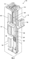
- FIG. 1 is a perspective view of an elevator system 101 including an elevator car 103, a counterweight 105, a tension member 107, a guide rail 109, a machine 111, a position reference system 113, and a controller 115.
- the elevator car 103 and counterweight 105 are connected to each other by the tension member 107.
- the tension member 107 may include or be configured as, for example, ropes, steel cables, and/or coated-steel belts.
- the counterweight 105 is configured to balance a load of the elevator car 103 and is configured to facilitate movement of the elevator car 103 concurrently and in an opposite direction with respect to the counterweight 105 within an elevator shaft 117 and along the guide rail 109.
- the tension member 107 engages the machine 111, which is part of an overhead structure of the elevator system 101.
- the machine 111 is configured to control movement between the elevator car 103 and the counterweight 105.
- the position reference system 113 may be mounted on a fixed part at the top of the elevator shaft 117, such as on a support or guide rail, and may be configured to provide position signals related to a position of the elevator car 103 within the elevator shaft 117. In other embodiments, the position reference system 113 may be directly mounted to a moving component of the machine 111, or may be located in other positions and/or configurations as known in the art.
- the position reference system 113 can be any device or mechanism for monitoring a position of an elevator car and/or counter weight, as known in the art.
- the position reference system 113 can be an encoder, sensor, or other system and can include velocity sensing, absolute position sensing, etc., as will be appreciated by those of skill in the art.
- the controller 115 is located, as shown, in a controller room 121 of the elevator shaft 117 and is configured to control the operation of the elevator system 101, and particularly the elevator car 103.
- the controller 115 may provide drive signals to the machine 111 to control the acceleration, deceleration, leveling, stopping, etc. of the elevator car 103.
- the controller 115 may also be configured to receive position signals from the position reference system 113 or any other desired position reference device.
- the elevator car 103 may stop at one or more landings 125 as controlled by the controller 115.
- the controller 115 can be located and/or configured in other locations or positions within the elevator system 101. In one embodiment, the controller may be located remotely or in the cloud.
- the machine 111 may include a motor or similar driving mechanism.
- the machine 111 is configured to include an electrically driven motor.
- the power supply for the motor may be any power source, including a power grid, which, in combination with other components, is supplied to the motor.
- the machine 111 may include a traction sheave that imparts force to tension member 107 to move the elevator car 103 within elevator shaft 117.
- FIG. 1 is merely a non-limiting example presented for illustrative and explanatory purposes.
- the system comprises a conveyance system that moves passengers between floors and/or along a single floor.
- conveyance systems may include escalators, people movers, etc.
- embodiments described herein are not limited to elevator systems, such as that shown in Figure 1 .
- embodiments disclosed herein may be applicable conveyance systems such as an elevator system 101 and a conveyance apparatus of the conveyance system such as an elevator car 103 of the elevator system 101.
- embodiments disclosed herein may be applicable conveyance systems such as an escalator system and a conveyance apparatus of the conveyance system such as a moving stair of the escalator system.
- the sensing apparatus 210 is configured to detect sensor data 202 of the elevator car 103 and transmit the sensor data 202 to a remote device 280.
- Sensor data 202 may include but is not limited to pressure data 314, vibratory signatures (i.e., vibrations over a period of time) or accelerations 312 and derivatives or integrals of accelerations 312 of the elevator car 103, such as, for example, distance, velocity, jerk, jounce, snap... etc.
- Sensor data 202 may also include light, sound, humidity, and temperature, or any other desired data parameter.
- the pressure data 314 may include atmospheric air pressure within the elevator shaft 117. It should be appreciated that, although particular systems are separately defined in the schematic block diagrams, each or any of the systems may be otherwise combined or separated via hardware and/or software.
- the sensing apparatus 210 may be a single sensor or may be multiple separate sensors that are interconnected.
- the sensing apparatus 210 is configured to transmit sensor data 202 that is raw and unprocessed to the controller 115 of the elevator system 101 for processing. In another embodiment, the sensing apparatus 210 is configured to process the sensor data 202 prior to transmitting the sensor data 202 to the controller 115. In another embodiment, the sensing apparatus 210 is configured to transmit sensor data 202 that is raw and unprocessed to a remote system 280 for processing. In yet another embodiment, the sensing apparatus 210 is configured to process the sensor data 202 prior to transmitting the sensor data 202 to the remote device 280.
- the processing of the sensor data 202 may reveal data, such as, for example, a number of elevator door openings/closings, elevator door time, vibrations, vibratory signatures, a number of elevator rides, elevator ride performance, elevator flight time, probable car position (e.g. elevation, floor number), releveling events, rollbacks, elevator car 103 x, y acceleration at a position: (i.e., rail topology), elevator car 103 x, y vibration signatures at a position: (i.e., rail topology), door performance at a landing number, nudging event, vandalism events, emergency stops, etc.
- data such as, for example, a number of elevator door openings/closings, elevator door time, vibrations, vibratory signatures, a number of elevator rides, elevator ride performance, elevator flight time, probable car position (e.g. elevation, floor number), releveling events, rollbacks, elevator car 103 x, y acceleration at a position: (i.e., rail topology),
- the remote device 280 may be a computing device, such as, for example, a desktop or cloud computer.
- the remote device 280 may also be a mobile computing device that is typically carried by a person, such as, for example a smartphone, PDA, smartwatch, tablet, laptop, etc.
- the remote device 280 may also be two separate devices that are synced together, such as, for example, a cellular phone and a desktop computer synced over an internet connection.
- the remote device 280 may also be a cloud computing network.
- the sensing apparatus 210 is configured to transmit the sensor data 202 to the controller 115 or the remote device 280 via short-range wireless protocols 203 and/or long-range wireless protocols 204.
- Short-range wireless protocols 203 may include but are not limited to Bluetooth, Wi-Fi, HaLow (801.11ah), zWave, Zigbee, or Wireless M-Bus.
- the sensing apparatus 210 is configured to transmit the sensor data 202 to directly to the controller 115 or to a local gateway device 240 and the local gateway device 240 is configured to transmit the sensor data 202 to the remote device 280 through a network 250 or to the controller 115.
- the network 250 may be a computing network, such as, for example, a cloud computing network, cellular network, or any other computing network known to one of skill in the art.
- the sensing apparatus 210 is configured to transmit the sensor data 202 to the remote device 280 through a network 250.
- Long-range wireless protocols 204 may include but are not limited to cellular, satellite, LTE (NB-IoT, CAT M1), LoRa, Satellite, Ingenu, or SigFox.
- the sensing apparatus 210 may be configured to detect sensor data 202 including acceleration in any number of directions.
- the sensing apparatus may detect sensor data 202 including accelerations 312 along three axis, an X axis, a Y axis, and a Z axis, as show in in FIG. 2 .
- the X axis may be perpendicular to the doors 104 of the elevator car 103, as shown in FIG. 2 .
- the Y axis may be parallel to the doors 104 of the elevator car 103, as shown in FIG. 2 .
- the Z axis may be aligned vertically parallel with the elevator shaft 117 and pull of gravity, as shown in FIG. 2 .
- Vibratory signatures may be generated along the X-axis and the Y-axis as the elevator car 103 moves along the Z-axis.
- the vibratory signatures may be utilized to determine a location of the elevator car 103 and/or a health level of the elevator system 101.
- the mobile device 600 may belong to an elevator mechanic/technician working on the elevator system 100.
- the mobile device 600 may be a mobile computing device that is typically carried by a person, such as, for example a smart phone, PDA, smart watch, tablet, laptop, etc.
- the mobile device 600 may include a touch screen (not shown).
- the mobile device 600 may include a processor 620, memory 610, a communication module 630, and an application, as shown in FIG. 2 .
- the processor 620 can be any type or combination of computer processors, such as a microprocessor, microcontroller, digital signal processor, application specific integrated circuit, programmable logic device, and/or field programmable gate array.
- the memory 610 is an example of a non-transitory computer readable storage medium tangibly embodied in the mobile device 600 including executable instructions stored therein, for instance, as firmware.
- the communication module 630 may implement one or more communication protocols, such as, for example, short-range wireless protocols 203 and long-range wireless protocols 204.
- the communication module 630 may be in communication with at least one of the controller 115, the sensing apparatus 210, the network 250, and the remote device 280.
- the communication module 630 is configured to receive a health level of the elevator system 101 from at least one of the controller 115, the sensing apparatus 210, the network 250, and the remote device 280.
- the application 640 is configured to generate a graphical user interface on the mobile device 600.
- the application 640 may be computer software installed directly on the memory 610 of the mobile device 600 and/or installed remotely and accessible through the mobile device 600 (e.g., software as a service).
- the mobile device 600 may also include a pressure sensor 690 configured to detect an ambient air pressure local to the mobile device 600, such as, for example, atmospheric air pressure.
- the pressure sensor 690 may be a pressure altimeter or barometric altimeter in two non-limiting examples.
- the pressure sensor 690 is in communication with the processor 620 and the processor 620 may be configured to determine a height or elevation of the mobile device 600 in response to the ambient air pressure detected local to the mobile device 600.
- a height or elevation of the mobile device may be determined using other location determination methods, including, but not limited to, cell triangulation, a global positioning system (GPS) and/or detection of wireless signal strength (e.g., received signal strength (RSS) using Bluetooth, Wi-FI,...etc).
- GPS global positioning system
- RSS received signal strength
- FIG. 3 shows a possible installation location of the sensing apparatus 210 within the elevator system 101.
- the sensing apparatus 210 may include a magnet (not show) to removably attach to the elevator car 103.
- the sensing apparatus 210 may be installed on the door hanger 104a and/or the door 104 of the elevator system 101. It is understood that the sensing apparatus 210 may also be installed in other locations other than the door hanger 104a and the door 104 of the elevator system 101. It is also understood that multiple sensing apparatus 210 are illustrated in FIG. 3 to show various locations of the sensing apparatus 210 and the embodiments disclosed herein may include one or more sensing apparatus 210.
- the sensing apparatus 210 may be attached to a door header 104e of a door 104 of the elevator car 103. In another embodiment, the sensing apparatus 210 may be located on a door header 104e proximate a top portion 104f of the elevator car 103. In another embodiment, the sensing apparatus 210 is installed elsewhere on the elevator car 103, such as, for example, directly on the door 104.
- the sensing apparatus 201 may be located on the elevator car 103 in the selected areas 106, as shown in FIG. 3 .
- the doors 104 are operably connected to the door header 104e through a door hanger 104a located proximate a top portion 104b of the door 104.
- the door hanger 104a includes guide wheels 104c that allow the door 104 to slide open and close along a guide rail 104d on the door header 104e.
- the door hanger 104a is an easy to access area to attach the sensing apparatus 210 because the door hanger 104a is accessible when the elevator car 103 is at landing 125 and the elevator door 104 is open.
- the door hanger 104a also provides ample clearance for the sensing apparatus 210 during operation of the elevator car 103, such as, for example, door 104 opening and closing. Due to the mounting location of the sensing apparatus 210 on the door hanger 104a, the sensing apparatus 210 may detect open and close motions (i.e., acceleration) of the door 104 of the elevator car 103 and a door at the landing 125. Additionally mounting the sensing apparatus 210 on the hanger 104a allows for recording of a ride quality of the elevator car 103.
- FIG. 4 illustrates a block diagram of the sensing apparatus 210 of the sensing system of FIGs. 2 and 3 . It should be appreciated that, although particular systems are separately defined in the schematic block diagram of FIG. 4 , each or any of the systems may be otherwise combined or separated via hardware and/or software. As shown in FIG. 4 , the sensing apparatus 210 may include a controller 212, a plurality of sensors 217 in communication with the controller 212, a communication module 220 in communication with the controller 212, and a power source 222 electrically connected to the controller 212.
- the plurality of sensors 217 includes an inertial measurement unit (IMU) sensor 218 configured to detect sensor data 202 including accelerations 312 of the sensing apparatus 210 and the elevator car 103 when the sensing apparatus 210 is attached to the elevator car 103.
- the IMU sensor 218 may be a sensor, such as, for example, an accelerometer, a gyroscope, or a similar sensor known to one of skill in the art.
- the accelerations 312 detected by the IMU sensor 218 may include accelerations 312 as well as derivatives or integrals of accelerations, such as, for example, velocity, jerk, jounce, snap... etc.
- the IMU sensor 218 is in communication with the controller 212 of the sensing apparatus 210.
- the plurality of sensors 217 includes a pressure sensor 228 is configured to detect sensor data 202 including pressure data 314, such as, for example, atmospheric air pressure within the elevator shaft 117.
- the pressure sensor 228 may be a pressure altimeter or barometric altimeter in two non-limiting examples.
- the pressure sensor 228 is in communication with the controller 212.
- the plurality of sensors 217 may also include additional sensors including but not limited to a light sensor 226, a pressure sensor 228, a microphone 230, a humidity sensor 232, and a temperature sensor 234.
- the light sensor 226 is configured to detect sensor data 202 including light exposure.
- the light sensor 226 is in communication with the controller 212.
- the microphone 230 is configured to detect sensor data 202 including audible sound and sound levels.
- the microphone 230 is in communication with the controller 212.
- the humidity sensor 232 is configured to detect sensor data 202 including humidity levels.
- the humidity sensor 232 is in communication with the controller 212.
- the temperature sensor 234 is configured to detect sensor data 202 including temperature levels.
- the temperature sensor 234 is in communication with the controller 212.
- the controller 212 of the sensing apparatus 210 includes a processor 214 and an associated memory 216 comprising computer-executable instructions that, when executed by the processor 214, cause the processor 214 to perform various operations, such as, for example, processing the sensor data 202 collected by the IMU sensor 218, the light sensor 226, the pressure sensor 228, the microphone 230, the humidity sensor 232, and the temperature sensor 234.
- the controller 212 may process the accelerations 312 and/or the pressure data 314 in order to determine a probable location of the elevator car 103, discussed further below.
- the processor 214 may be but is not limited to a single-processor or multi-processor system of any of a wide array of possible architectures, including field programmable gate array (FPGA), central processing unit (CPU), application specific integrated circuits (ASIC), digital signal processor (DSP) or graphics processing unit (GPU) hardware arranged homogenously or heterogeneously.
- the memory 216 may be a storage device, such as, for example, a random access memory (RAM), read only memory (ROM), or other electronic, optical, magnetic or any other computer readable medium.
- the power source 222 of the sensing apparatus 210 is configured to store and supply electrical power to the sensing apparatus 210.
- the power source 222 may include an energy storage system, such as, for example, a battery system, capacitor, or other energy storage system known to one of skill in the art.
- the power source 222 may also generate electrical power for the sensing apparatus 210.
- the power source 222 may also include an energy generation or electricity harvesting system, such as, for example synchronous generator, induction generator, or other type of electrical generator known to one of skill in the art.
- the sensing apparatus 210 includes a communication module 220 configured to allow the controller 212 of the sensing apparatus 210 to communicate with the remote device 280 or controller 115 through at least one of short-range wireless protocols 203 and long-range wireless protocols 204.
- the communication module 220 may be configured to communicate with the remote device 280 using short-range wireless protocols 203, such as, for example, Bluetooth, Wi-Fi, HaLow (801.11ah), Wireless M-Bus, zWave, Zigbee, or other short-range wireless protocol known to one of skill in the art.
- the communication module 220 is configured to transmit the sensor data 202 to a local gateway device 240 and the local gateway device 240 is configured to transmit the sensor data to a remote device 280 through a network 250, as described above.
- the communication module 220 may be configured to communicate with the remote device 280 using long-range wireless protocols 204, such as for example, cellular, LTE (NB-IoT, CAT M1), LoRa, Ingenu, SigFox, Satellite, or other long-range wireless protocol known to one of skill in the art.
- long-range wireless protocols 204 the communication module 220 is configured to transmit the sensor data 202 to a remote device 280 through a network 250.
- the short-range wireless protocol 203 is sub GHz Wireless M-Bus.
- the long-range wireless protocol is Sigfox.
- the long-range wireless protocol is LTE NB-IoT or CAT M1 with 2G fallback.
- the sensing apparatus 210 includes a location determination module 330 configured to determine a location (i.e., position) of the elevator car 103 within the elevator shaft 117.
- the location of the elevator car 103 may be fixed locations along the elevator shaft 117, such as for example, the landings 125 of the elevator shaft 117.
- the locations may be equidistantly spaced apart along the elevator shaft 117 or intermittently spaced apart along the elevator shaft 117.
- the location determination module 330 may utilize various approaches to determine a location of the elevator car 103 within the elevator shaft 117.
- the location determination module 330 may be configured to determine a location of the elevator car 103 within the elevator shaft 117 using at least one of a pressure location determination module 310 and an acceleration location determination module 320.
- the acceleration location determination module 320 is configured to determine a distance traveled of the elevator car 103 within the elevator shaft 117 in response to the acceleration of the elevator car 103 detected along the Y axis.
- the sensing apparatus 210 may detect an acceleration along the Y axis shown at 322 and may integrate the acceleration to get a velocity of the elevator car 103 at 324.
- the sensing apparatus 210 may also integrate the velocity of the elevator car 103 to determine a distance traveled by the elevator car 103 within the elevator shaft 117 during the acceleration 312 detected at 322.
- the direction of travel of the elevator car 103 may also be determined in response to the acceleration 312 detected.
- the location determination module 330 may then determine the location of the elevator car 103 within the elevator shaft 117 in response to a starting location and a distance traveled away from that probable starting location.
- the starting location may be based upon tracking the past operation and/or movement of the elevator car 103.
- the pressure location determination module 310 is configured to detect an atmospheric air pressure within the elevator shaft 117 when the elevator car 103 is in motion and/or stationary using the pressure sensor 228.
- the pressure detected by the pressure sensor 228 may be associated with a location (e.g., height, elevation) within the elevator shaft 117 through either a look up table or a calculation of altitude using the barometric pressure change in two non-limiting embodiments.
- the direction of travel of the elevator car 103 may also be determined in response to the change in pressure detected via the pressure data 314.
- the pressure sensor 228 may need to periodically detect a baseline pressure to account for changes in atmospheric pressure due to local weather conditions. For example, this baseline pressure may need to be detected daily, hourly, or weekly in non-limiting embodiments.
- the baseline pressure may be detected whenever the elevator car 103 is stationary, or at certain intervals when the elevator car 103 is stationary.
- the acceleration of the elevator car 103 may also need to be detected to know when the elevator car 103 is stationary and when the elevator car 103 is stationary the sensing apparatus 210 may need to be offset to compensate the sensor drift and environment drift.
- the pressure location determination module 310 may be used to verify and/or modify a location of the elevator car 102 within the elevator shaft 117 determined by the acceleration location determination module 320.
- the acceleration location determination module 320 may be used to verify and/or modify a location of the elevator car 102 within the elevator shaft 117 determined by the pressure location determination module 310.
- the pressure location determination module 310 may be prompted to determine a location of the elevator car 103 within the elevator shaft 117 in response to an acceleration detected by the IMU sensor 218.
- the controller 212 may process the sound detected by the microphone 230, the light detected by the light sensor 226, the humidity detected by the humidity sensor 232, the temperature detected by the temperature sensor 234, the accelerations 312 detected by the IM sensor 218, and/or the pressure data 314 detected by the pressure sensor 228 in order to determine a health level 710 (see FIG. 6 ) of the elevator system 101.
- the health level may be a graded scale indicating the health of the elevator system 101. In a non-limiting example, the health level may be graded on a scale of one-to-ten with a health level equivalent to one being the lowest health level and a health level equivalent to ten being the highest health level.
- the health level may be graded on a scale of one-to-one-hundred percent with a health level equivalent to one percent being the lowest health level and a health level equivalent to one-hundred percent being the highest health level.
- the health level may be determined in response to the accelerations 312 detected. For example, accelerations 312 above a threshold acceleration (e.g., normal operating acceleration) in any one of the X axis, a Y axis, and a Z axis may be indicative of a low health level.
- a threshold acceleration e.g., normal operating acceleration
- the controller 212 is configured to assign a determined health level to locations along the elevator shaft 117 where the health level was determined. The health level may then be communicated to the mobile device 600 where it is visible to a user of the mobile device 600.
- the health level of the elevator system 101 may be determined at various location along the elevator shaft 117. In one example, the health level of the elevator system 101 may be determined intermittently along the elevator shaft 117. In another example, the health level of the elevator system 101 may be determined at each landing 125 along the elevator shaft 117.
- FIG. 5 shows a flow chart of a method 500 of monitoring a conveyance system, in accordance with an embodiment of the present disclosure.
- the conveyance system is an elevator system 101 and the conveyance apparatus is an elevator car 103.
- the method 500 may be performed by the application 640 of the mobile device 600.
- FIG. 6 illustrates a mobile device 600 generating graphical user interface 670 via display device 650 for viewing and interacting with the application 640 illustrated in FIG. 1 .
- the mobile device 600 may be a laptop computer, smart phone, tablet computer, smart watch, or any other mobile computing device known to one of skill in the art. In the example shown in FIG.
- the mobile device 600 is a touchscreen smart phone.
- the mobile device 600 includes the display device 650 and an input device 652, such as, example, a mouse, a touch screen, a scroll wheel, a scroll ball, a stylus pen, a microphone, a camera, etc.
- the display device 650 may also function as an input device 652.
- FIG. 6 illustrates a graphical user interface 670 generated on the display device 650 of the mobile device 600.
- a user may interact with the graphical user interface 670 through a selection input, such as, for example, a "click", "touch”, verbal command, gesture recognition, or any other input to the user interface 670.
- a health level 710 of the conveyance system may be obtained at a first conveyance apparatus location 730a.
- the health level 710 may be obtained at a plurality of conveyance apparatus locations 730, including the first conveyance apparatus location 730a, during normal operation of the conveyance system and/or a specific run of the conveyance apparatus.
- the health level 710 may include a first health level 710a determined at a first time and a second health level 710b determined at a second time.
- the first health level 710a may be determined prior to maintenance being performed on the conveyance system and a second health level 710b may be determined after the maintenance is performed on the conveyance system.
- a first identifier 740a for the first conveyance apparatus location 730a is determined.
- the conveyance system is an elevator system 101
- the first identifier 740a may be a formal floor number of a landing 125.
- the method 500 may further comprise: normalizing the first identifier 740a for the first conveyance apparatus location 730a to a standard value.
- the bottom floor may be referred to as the first floor however may later be normalized to floor zero, which may be the standard value.
- the first identifier 740a may indicate that the elevator car 103 is at the 14 th floor of the elevator system 101 and the 14 th floor may be normalized to the 13 th floor.
- the conveyance system is an elevator system 101 that has skipped a number of landings 125 in a building to make the building appear larger, then the identifier 740 of each landing 125 may be normalized by starting from the bottom floor at zero and moving up counting each landing 125 and assigning the appropriate sequential (e.g., 1, 2, 3,...etc.) identifier 740 to each landing 125. If the health level 710 is obtained at a plurality of conveyance apparatus locations 730 then the identifier 740 of each of the plurality of conveyance apparatus locations 730 may be normalized.
- the health level 710 for the conveyance system at the first conveyance apparatus location 730a and the first identifier 740a for the first conveyance apparatus location 730a may be displayed on a display device 650.
- a current location of an individual 750 within the conveyance system is determined.
- the current location of the individual 750 within the conveyance system may be determined by: detecting an ambient air pressure proximate the individual; and determining an elevation in response to the ambient air pressure.
- the ambient air pressure proximate the individual may be determined using a pressure sensor 690 of a mobile device 600 carried by the individual.
- the current location of the individual 750 within the conveyance system may be determined by: determining that the individual is currently located within the conveyance apparatus; determining a current location of the conveyance apparatus; and determining that the current location of the individual is equivalent to the current location of the conveyance apparatus.
- the individual may be determined to be within the conveyance apparatus by tracking a location of a mobile device 600 carried by the individual. The location of the mobile device 600 may be tracked through GPS, cell triangulation, and/or RSS.
- the current location of the individual 750 within the conveyance system may be determined by: detecting a wireless signal of a mobile device 600 being carried by an individual; and determining RSS of the mobile device 600; and determining an elevation of the individual in response to the RSS of the mobile device 600.
- the current location of the individual 750 may be located at the first conveyance apparatus location 730a or the individual 750 may not be located at the first conveyance apparatus location 730a (e.g., a second conveyance apparatus location 730b).
- the location of the individual 750 within the conveyance system is displayed on the display device 650.
- the location of the individual 750 is displayed relative to the health level 710 for the conveyance system at the first conveyance apparatus location 730a.
- the current location of the conveyance apparatus 720 may also be determined and displayed on the display device 650.
- the method 500 may further comprise: obtaining a health level 710 of the conveyance system at a second conveyance apparatus location 730b; determining a second identifier 740b for the second conveyance apparatus location 730b; and displaying the health level 710 for the conveyance system at the second conveyance apparatus location 730b and the second identifier 740b for the second conveyance apparatus location on a display device 750.
- the health level 710 for the conveyance system at the second conveyance apparatus location 730b and the second identifier 740b for the second conveyance apparatus location on a display device 750 may be displayed simultaneously with the health level 710 for the conveyance system at the first conveyance apparatus location 730a and the first identifier 740a for the first conveyance apparatus location 730a may be displayed on a display device 650, as shown in FIG. 6 .
- the method 500 may further comprise: normalizing the first identifier 740b for the first conveyance apparatus location 730a to a standard value.
- the current location of the individual 750 may be located at the second conveyance apparatus location 730b or the individual 750 may not be located at the second conveyance apparatus location 730b (e.g., the first conveyance apparatus location 730a).
Abstract
Description
- The embodiments herein relate to the field of conveyance systems, and specifically to a method and apparatus for monitoring a conveyance apparatus of a conveyance system.
- A position of a conveyance apparatus within a conveyance systems, such as, for example, elevator systems, escalator systems, and moving walkways may typically be difficult to determine.
- According to an embodiment, a method of monitoring a conveyance apparatus within a conveyance system is provided. The method including: obtaining a health level of the conveyance system at a first conveyance apparatus location; determining a first identifier for the first conveyance apparatus location; displaying the health level for the conveyance system at the first conveyance apparatus location and the first identifier for the first conveyance apparatus location on a display device; determining a current location of an individual within the conveyance system; and displaying the location of the individual within the conveyance system on the display device.
- In addition to one or more of the features described herein, further embodiments may include that prior to displaying the health level for the conveyance system at the first conveyance apparatus location and the first identifier for the first conveyance apparatus location on a display device, the method further includes: normalizing the first identifier for the first conveyance apparatus location to a standard value.
- In addition to one or more of the features described herein, or as an alternative, further embodiments may include that determining a current location of an individual within the conveyance system, further includes: detecting an ambient air pressure proximate the individual; and determining an elevation in response to the ambient air pressure.
- In addition to one or more of the features described herein, or as an alternative, further embodiments may include that determining a current location of an individual within the conveyance system, further includes: detecting a wireless signal of a mobile device being carried by an individual; and determining received signal strength of the mobile device; and determining an elevation of the individual in response to the received signal strength of the mobile device.
- In addition to one or more of the features described herein, or as an alternative, further embodiments may include that determining a current location of an individual within the conveyance system, further includes: determining that the individual is currently located within the conveyance apparatus; determining a current location of the conveyance apparatus; and determining that the current location of the individual is equivalent to the current location of the conveyance apparatus.
- In addition to one or more of the features described herein, or as an alternative, further embodiments may include that the current location of the individual is located at the first conveyance apparatus location.
- In addition to one or more of the features described herein, or as an alternative, further embodiments may include that the current location of the individual is not located at the first conveyance apparatus location.
- In addition to one or more of the features described herein, or as an alternative, further embodiments may include: obtaining a health level of the conveyance system at a second conveyance apparatus location; determining a second identifier for the second conveyance apparatus location; and displaying the health level for the conveyance system at the second conveyance apparatus location and the second identifier for the second conveyance apparatus location on a display device.
- In addition to one or more of the features described herein, or as an alternative, further embodiments may include that prior to displaying the health level for the conveyance system at the first conveyance apparatus location and the first identifier for the first conveyance apparatus location on a display device, the method further includes: normalizing the first identifier for the first conveyance apparatus location to a standard value, and wherein prior to displaying the health level for the conveyance system at the second conveyance apparatus location and the second identifier for the second conveyance apparatus location on a display device, the method further includes normalizing the first identifier for the first conveyance apparatus location to a standard value.
- In addition to one or more of the features described herein, or as an alternative, further embodiments may include that the current location of the individual is located at the second conveyance apparatus location.
- In addition to one or more of the features described herein, or as an alternative, further embodiments may include that the current location of the individual is not located at the second conveyance apparatus location.
- In addition to one or more of the features described herein, or as an alternative, further embodiments may include that the conveyance system is an elevator system and the conveyance apparatus is an elevator car.
- According to another embodiment, a computer program product embodied on a non-transitory computer readable medium is provided. The computer program product including instructions that, when executed by a processor, cause the processor to perform operations including: obtaining a health level of the conveyance system at a first conveyance apparatus location; determining a first identifier for the first conveyance apparatus location; displaying the health level for the conveyance system at the first conveyance apparatus location and the first identifier for the first conveyance apparatus location on a display device; determining a current location of an individual within the conveyance system; and displaying the location of the individual within the conveyance system on the display device.
- In addition to one or more of the features described herein, further embodiments may include that prior to displaying the health level for the conveyance system at the first conveyance apparatus location and the first identifier for the first conveyance apparatus location on a display device, the operations further include: normalizing the first identifier for the first conveyance apparatus location to a standard value.
- In addition to one or more of the features described herein, or as an alternative, further embodiments may include that determining a current location of an individual within the conveyance system further includes: detecting an ambient air pressure proximate the individual; and determining an elevation in response to the ambient air pressure.
- In addition to one or more of the features described herein, or as an alternative, further embodiments may include that determining a current location of an individual within the conveyance system, further includes: detecting a wireless signal of a mobile device being carried by an individual; and determining received signal strength of the mobile device; and determining an elevation of the individual in response to the received signal strength of the mobile device.
- In addition to one or more of the features described herein, or as an alternative, further embodiments may include that determining a current location of an individual within the conveyance system further includes: determining that the individual is currently located within the conveyance apparatus; determining a current location of the conveyance apparatus; and determining that the current location of the individual is equivalent to the current location of the conveyance apparatus.
- In addition to one or more of the features described herein, or as an alternative, further embodiments may include that the current location of the individual is located at the first conveyance apparatus location.
- In addition to one or more of the features described herein, or as an alternative, further embodiments may include that the operations further include: obtaining a health level of the conveyance system at a second conveyance apparatus location; determining a second identifier for the second conveyance apparatus location; and displaying the health level for the conveyance system at the second conveyance apparatus location and the second identifier for the second conveyance apparatus location on a display device.
- According to another embodiment, a system for monitoring a conveyance apparatus within a conveyance system is provided. The system including: a processor; and a memory including computer-executable instructions that, when executed by the processor, cause the processor to perform operations, the operations including: obtaining a health level of the conveyance system at a first conveyance apparatus location; determining a first identifier for the first conveyance apparatus location; displaying the health level for the conveyance system at the first conveyance apparatus location and the first identifier for the first conveyance apparatus location on a display device; determining a current location of an individual within the conveyance system; and displaying the location of the individual within the conveyance system on the display device.
- Technical effects of embodiments of the present disclosure include simultaneously displaying conveyance system health along with a location of an individual within the conveyance system on a single display device.
- The foregoing features and elements may be combined in various combinations without exclusivity, unless expressly indicated otherwise. These features and elements as well as the operation thereof will become more apparent in light of the following description and the accompanying drawings. It should be understood, however, that the following description and drawings are intended to be illustrative and explanatory in nature and non-limiting.
- The present disclosure is illustrated by way of example and not limited in the accompanying figures in which like reference numerals indicate similar elements.
-
FIG. 1 is a schematic illustration of an elevator system that may employ various embodiments of the present disclosure; -
FIG. 2 is a schematic illustration of a sensor system for the elevator system ofFIG. 1 , in accordance with an embodiment of the disclosure; -
FIG. 3 is a schematic illustration of the location of sensing apparatus of the sensor system ofFIG. 2 , in accordance with an embodiment of the disclosure; -
FIG. 4 is a schematic illustration of a sensing apparatus of the sensor system ofFIG. 2 , in accordance with an embodiment of the disclosure; and -
FIG. 5 is a flow chart of a method of monitoring a conveyance apparatus within a conveyance system, in accordance with an embodiment of the disclosure; and -
FIG. 6 illustrates a mobile device graphical user interface for viewing and interacting with an application, in accordance with an embodiment of the disclosure. -
FIG. 1 is a perspective view of anelevator system 101 including anelevator car 103, acounterweight 105, atension member 107, aguide rail 109, amachine 111, aposition reference system 113, and acontroller 115. Theelevator car 103 andcounterweight 105 are connected to each other by thetension member 107. Thetension member 107 may include or be configured as, for example, ropes, steel cables, and/or coated-steel belts. Thecounterweight 105 is configured to balance a load of theelevator car 103 and is configured to facilitate movement of theelevator car 103 concurrently and in an opposite direction with respect to thecounterweight 105 within anelevator shaft 117 and along theguide rail 109. - The
tension member 107 engages themachine 111, which is part of an overhead structure of theelevator system 101. Themachine 111 is configured to control movement between theelevator car 103 and thecounterweight 105. Theposition reference system 113 may be mounted on a fixed part at the top of theelevator shaft 117, such as on a support or guide rail, and may be configured to provide position signals related to a position of theelevator car 103 within theelevator shaft 117. In other embodiments, theposition reference system 113 may be directly mounted to a moving component of themachine 111, or may be located in other positions and/or configurations as known in the art. Theposition reference system 113 can be any device or mechanism for monitoring a position of an elevator car and/or counter weight, as known in the art. For example, without limitation, theposition reference system 113 can be an encoder, sensor, or other system and can include velocity sensing, absolute position sensing, etc., as will be appreciated by those of skill in the art. - The
controller 115 is located, as shown, in acontroller room 121 of theelevator shaft 117 and is configured to control the operation of theelevator system 101, and particularly theelevator car 103. For example, thecontroller 115 may provide drive signals to themachine 111 to control the acceleration, deceleration, leveling, stopping, etc. of theelevator car 103. Thecontroller 115 may also be configured to receive position signals from theposition reference system 113 or any other desired position reference device. When moving up or down within theelevator shaft 117 alongguide rail 109, theelevator car 103 may stop at one ormore landings 125 as controlled by thecontroller 115. Although shown in acontroller room 121, those of skill in the art will appreciate that thecontroller 115 can be located and/or configured in other locations or positions within theelevator system 101. In one embodiment, the controller may be located remotely or in the cloud. - The
machine 111 may include a motor or similar driving mechanism. In accordance with embodiments of the disclosure, themachine 111 is configured to include an electrically driven motor. The power supply for the motor may be any power source, including a power grid, which, in combination with other components, is supplied to the motor. Themachine 111 may include a traction sheave that imparts force totension member 107 to move theelevator car 103 withinelevator shaft 117. - Although shown and described with a roping system including
tension member 107, elevator systems that employ other methods and mechanisms of moving an elevator car within an elevator shaft may employ embodiments of the present disclosure. For example, embodiments may be employed in ropeless elevator systems using a linear motor to impart motion to an elevator car. Embodiments may also be employed in ropeless elevator systems using a hydraulic lift to impart motion to an elevator car.FIG. 1 is merely a non-limiting example presented for illustrative and explanatory purposes. - In other embodiments, the system comprises a conveyance system that moves passengers between floors and/or along a single floor. Such conveyance systems may include escalators, people movers, etc. Accordingly, embodiments described herein are not limited to elevator systems, such as that shown in
Figure 1 . In one example, embodiments disclosed herein may be applicable conveyance systems such as anelevator system 101 and a conveyance apparatus of the conveyance system such as anelevator car 103 of theelevator system 101. In another example, embodiments disclosed herein may be applicable conveyance systems such as an escalator system and a conveyance apparatus of the conveyance system such as a moving stair of the escalator system. - Referring now to
FIG. 2 , with continued referenced toFIG. 1 , a view of asensor system 200 including asensing apparatus 210 is illustrated, according to an embodiment of the present disclosure. Thesensing apparatus 210 is configured to detectsensor data 202 of theelevator car 103 and transmit thesensor data 202 to aremote device 280.Sensor data 202 may include but is not limited to pressuredata 314, vibratory signatures (i.e., vibrations over a period of time) oraccelerations 312 and derivatives or integrals ofaccelerations 312 of theelevator car 103, such as, for example, distance, velocity, jerk, jounce, snap... etc.Sensor data 202 may also include light, sound, humidity, and temperature, or any other desired data parameter. Thepressure data 314 may include atmospheric air pressure within theelevator shaft 117. It should be appreciated that, although particular systems are separately defined in the schematic block diagrams, each or any of the systems may be otherwise combined or separated via hardware and/or software. For example, thesensing apparatus 210 may be a single sensor or may be multiple separate sensors that are interconnected. - In an embodiment, the
sensing apparatus 210 is configured to transmitsensor data 202 that is raw and unprocessed to thecontroller 115 of theelevator system 101 for processing. In another embodiment, thesensing apparatus 210 is configured to process thesensor data 202 prior to transmitting thesensor data 202 to thecontroller 115. In another embodiment, thesensing apparatus 210 is configured to transmitsensor data 202 that is raw and unprocessed to aremote system 280 for processing. In yet another embodiment, thesensing apparatus 210 is configured to process thesensor data 202 prior to transmitting thesensor data 202 to theremote device 280. - The processing of the
sensor data 202 may reveal data, such as, for example, a number of elevator door openings/closings, elevator door time, vibrations, vibratory signatures, a number of elevator rides, elevator ride performance, elevator flight time, probable car position (e.g. elevation, floor number), releveling events, rollbacks, elevator car 103 x, y acceleration at a position: (i.e., rail topology), elevator car 103 x, y vibration signatures at a position: (i.e., rail topology), door performance at a landing number, nudging event, vandalism events, emergency stops, etc. - The
remote device 280 may be a computing device, such as, for example, a desktop or cloud computer. Theremote device 280 may also be a mobile computing device that is typically carried by a person, such as, for example a smartphone, PDA, smartwatch, tablet, laptop, etc. Theremote device 280 may also be two separate devices that are synced together, such as, for example, a cellular phone and a desktop computer synced over an internet connection. Theremote device 280 may also be a cloud computing network. - The
sensing apparatus 210 is configured to transmit thesensor data 202 to thecontroller 115 or theremote device 280 via short-range wireless protocols 203 and/or long-range wireless protocols 204. Short-range wireless protocols 203 may include but are not limited to Bluetooth, Wi-Fi, HaLow (801.11ah), zWave, Zigbee, or Wireless M-Bus. Using short-range wireless protocols 203, thesensing apparatus 210 is configured to transmit thesensor data 202 to directly to thecontroller 115 or to alocal gateway device 240 and thelocal gateway device 240 is configured to transmit thesensor data 202 to theremote device 280 through anetwork 250 or to thecontroller 115. Thenetwork 250 may be a computing network, such as, for example, a cloud computing network, cellular network, or any other computing network known to one of skill in the art. Using long-range wireless protocols 204, thesensing apparatus 210 is configured to transmit thesensor data 202 to theremote device 280 through anetwork 250. Long-range wireless protocols 204 may include but are not limited to cellular, satellite, LTE (NB-IoT, CAT M1), LoRa, Satellite, Ingenu, or SigFox. - The
sensing apparatus 210 may be configured to detectsensor data 202 including acceleration in any number of directions. In an embodiment, the sensing apparatus may detectsensor data 202 includingaccelerations 312 along three axis, an X axis, a Y axis, and a Z axis, as show in inFIG. 2 . The X axis may be perpendicular to thedoors 104 of theelevator car 103, as shown inFIG. 2 . The Y axis may be parallel to thedoors 104 of theelevator car 103, as shown inFIG. 2 . The Z axis may be aligned vertically parallel with theelevator shaft 117 and pull of gravity, as shown inFIG. 2 . Vibratory signatures may be generated along the X-axis and the Y-axis as theelevator car 103 moves along the Z-axis. The vibratory signatures may be utilized to determine a location of theelevator car 103 and/or a health level of theelevator system 101. - Also shown in
FIG. 2 is amobile device 600. Themobile device 600 may belong to an elevator mechanic/technician working on the elevator system 100. Themobile device 600 may be a mobile computing device that is typically carried by a person, such as, for example a smart phone, PDA, smart watch, tablet, laptop, etc. Themobile device 600 may include a touch screen (not shown). Themobile device 600 may include aprocessor 620,memory 610, acommunication module 630, and an application, as shown inFIG. 2 . Theprocessor 620 can be any type or combination of computer processors, such as a microprocessor, microcontroller, digital signal processor, application specific integrated circuit, programmable logic device, and/or field programmable gate array. Thememory 610 is an example of a non-transitory computer readable storage medium tangibly embodied in themobile device 600 including executable instructions stored therein, for instance, as firmware. Thecommunication module 630 may implement one or more communication protocols, such as, for example, short-range wireless protocols 203 and long-range wireless protocols 204. Thecommunication module 630 may be in communication with at least one of thecontroller 115, thesensing apparatus 210, thenetwork 250, and theremote device 280. Thecommunication module 630 is configured to receive a health level of theelevator system 101 from at least one of thecontroller 115, thesensing apparatus 210, thenetwork 250, and theremote device 280. Theapplication 640 is configured to generate a graphical user interface on themobile device 600. Theapplication 640 may be computer software installed directly on thememory 610 of themobile device 600 and/or installed remotely and accessible through the mobile device 600 (e.g., software as a service). - The
mobile device 600 may also include apressure sensor 690 configured to detect an ambient air pressure local to themobile device 600, such as, for example, atmospheric air pressure. Thepressure sensor 690 may be a pressure altimeter or barometric altimeter in two non-limiting examples. Thepressure sensor 690 is in communication with theprocessor 620 and theprocessor 620 may be configured to determine a height or elevation of themobile device 600 in response to the ambient air pressure detected local to themobile device 600. A height or elevation of the mobile device may be determined using other location determination methods, including, but not limited to, cell triangulation, a global positioning system (GPS) and/or detection of wireless signal strength (e.g., received signal strength (RSS) using Bluetooth, Wi-FI,...etc). -
FIG. 3 shows a possible installation location of thesensing apparatus 210 within theelevator system 101. Thesensing apparatus 210 may include a magnet (not show) to removably attach to theelevator car 103. In the illustrated embodiment shown inFIG. 3 , thesensing apparatus 210 may be installed on thedoor hanger 104a and/or thedoor 104 of theelevator system 101. It is understood that thesensing apparatus 210 may also be installed in other locations other than thedoor hanger 104a and thedoor 104 of theelevator system 101. It is also understood thatmultiple sensing apparatus 210 are illustrated inFIG. 3 to show various locations of thesensing apparatus 210 and the embodiments disclosed herein may include one ormore sensing apparatus 210. In another embodiment, thesensing apparatus 210 may be attached to adoor header 104e of adoor 104 of theelevator car 103. In another embodiment, thesensing apparatus 210 may be located on adoor header 104e proximate atop portion 104f of theelevator car 103. In another embodiment, thesensing apparatus 210 is installed elsewhere on theelevator car 103, such as, for example, directly on thedoor 104. - As shown in
FIG. 3 , the sensing apparatus 201 may be located on theelevator car 103 in the selectedareas 106, as shown inFIG. 3 . Thedoors 104 are operably connected to thedoor header 104e through adoor hanger 104a located proximate atop portion 104b of thedoor 104. Thedoor hanger 104a includesguide wheels 104c that allow thedoor 104 to slide open and close along aguide rail 104d on thedoor header 104e. Advantageously, thedoor hanger 104a is an easy to access area to attach thesensing apparatus 210 because thedoor hanger 104a is accessible when theelevator car 103 is at landing 125 and theelevator door 104 is open. Thus, installation of thesensing apparatus 210 is possible without taking special measures to take control over theelevator car 103. For example, the additional safety of an emergency door stop to hold theelevator door 104 open is not necessary asdoor 104 opening at landing 125 is a normal operation mode. Thedoor hanger 104a also provides ample clearance for thesensing apparatus 210 during operation of theelevator car 103, such as, for example,door 104 opening and closing. Due to the mounting location of thesensing apparatus 210 on thedoor hanger 104a, thesensing apparatus 210 may detect open and close motions (i.e., acceleration) of thedoor 104 of theelevator car 103 and a door at thelanding 125. Additionally mounting thesensing apparatus 210 on thehanger 104a allows for recording of a ride quality of theelevator car 103. -
FIG. 4 illustrates a block diagram of thesensing apparatus 210 of the sensing system ofFIGs. 2 and 3 . It should be appreciated that, although particular systems are separately defined in the schematic block diagram ofFIG. 4 , each or any of the systems may be otherwise combined or separated via hardware and/or software. As shown inFIG. 4 , thesensing apparatus 210 may include acontroller 212, a plurality ofsensors 217 in communication with thecontroller 212, acommunication module 220 in communication with thecontroller 212, and apower source 222 electrically connected to thecontroller 212. - The plurality of
sensors 217 includes an inertial measurement unit (IMU)sensor 218 configured to detectsensor data 202 includingaccelerations 312 of thesensing apparatus 210 and theelevator car 103 when thesensing apparatus 210 is attached to theelevator car 103. TheIMU sensor 218 may be a sensor, such as, for example, an accelerometer, a gyroscope, or a similar sensor known to one of skill in the art. Theaccelerations 312 detected by theIMU sensor 218 may includeaccelerations 312 as well as derivatives or integrals of accelerations, such as, for example, velocity, jerk, jounce, snap... etc. TheIMU sensor 218 is in communication with thecontroller 212 of thesensing apparatus 210. - The plurality of
sensors 217 includes apressure sensor 228 is configured to detectsensor data 202 includingpressure data 314, such as, for example, atmospheric air pressure within theelevator shaft 117. Thepressure sensor 228 may be a pressure altimeter or barometric altimeter in two non-limiting examples. Thepressure sensor 228 is in communication with thecontroller 212. - The plurality of
sensors 217 may also include additional sensors including but not limited to alight sensor 226, apressure sensor 228, amicrophone 230, ahumidity sensor 232, and atemperature sensor 234. Thelight sensor 226 is configured to detectsensor data 202 including light exposure. Thelight sensor 226 is in communication with thecontroller 212. Themicrophone 230 is configured to detectsensor data 202 including audible sound and sound levels. Themicrophone 230 is in communication with thecontroller 212. Thehumidity sensor 232 is configured to detectsensor data 202 including humidity levels. Thehumidity sensor 232 is in communication with thecontroller 212. Thetemperature sensor 234 is configured to detectsensor data 202 including temperature levels. Thetemperature sensor 234 is in communication with thecontroller 212. - The
controller 212 of thesensing apparatus 210 includes aprocessor 214 and an associatedmemory 216 comprising computer-executable instructions that, when executed by theprocessor 214, cause theprocessor 214 to perform various operations, such as, for example, processing thesensor data 202 collected by theIMU sensor 218, thelight sensor 226, thepressure sensor 228, themicrophone 230, thehumidity sensor 232, and thetemperature sensor 234. In an embodiment, thecontroller 212 may process theaccelerations 312 and/or thepressure data 314 in order to determine a probable location of theelevator car 103, discussed further below. Theprocessor 214 may be but is not limited to a single-processor or multi-processor system of any of a wide array of possible architectures, including field programmable gate array (FPGA), central processing unit (CPU), application specific integrated circuits (ASIC), digital signal processor (DSP) or graphics processing unit (GPU) hardware arranged homogenously or heterogeneously. Thememory 216 may be a storage device, such as, for example, a random access memory (RAM), read only memory (ROM), or other electronic, optical, magnetic or any other computer readable medium. - The
power source 222 of thesensing apparatus 210 is configured to store and supply electrical power to thesensing apparatus 210. Thepower source 222 may include an energy storage system, such as, for example, a battery system, capacitor, or other energy storage system known to one of skill in the art. Thepower source 222 may also generate electrical power for thesensing apparatus 210. Thepower source 222 may also include an energy generation or electricity harvesting system, such as, for example synchronous generator, induction generator, or other type of electrical generator known to one of skill in the art. - The
sensing apparatus 210 includes acommunication module 220 configured to allow thecontroller 212 of thesensing apparatus 210 to communicate with theremote device 280 orcontroller 115 through at least one of short-range wireless protocols 203 and long-range wireless protocols 204. Thecommunication module 220 may be configured to communicate with theremote device 280 using short-range wireless protocols 203, such as, for example, Bluetooth, Wi-Fi, HaLow (801.11ah), Wireless M-Bus, zWave, Zigbee, or other short-range wireless protocol known to one of skill in the art. Using short-range wireless protocols 203, thecommunication module 220 is configured to transmit thesensor data 202 to alocal gateway device 240 and thelocal gateway device 240 is configured to transmit the sensor data to aremote device 280 through anetwork 250, as described above. Thecommunication module 220 may be configured to communicate with theremote device 280 using long-range wireless protocols 204, such as for example, cellular, LTE (NB-IoT, CAT M1), LoRa, Ingenu, SigFox, Satellite, or other long-range wireless protocol known to one of skill in the art. Using long-range wireless protocols 204, thecommunication module 220 is configured to transmit thesensor data 202 to aremote device 280 through anetwork 250. In an embodiment, the short-range wireless protocol 203 is sub GHz Wireless M-Bus. In another embodiment, the long-range wireless protocol is Sigfox. In another embodiment, the long-range wireless protocol is LTE NB-IoT or CAT M1 with 2G fallback. - The
sensing apparatus 210 includes alocation determination module 330 configured to determine a location (i.e., position) of theelevator car 103 within theelevator shaft 117. The location of theelevator car 103 may be fixed locations along theelevator shaft 117, such as for example, thelandings 125 of theelevator shaft 117. The locations may be equidistantly spaced apart along theelevator shaft 117 or intermittently spaced apart along theelevator shaft 117. - The
location determination module 330 may utilize various approaches to determine a location of theelevator car 103 within theelevator shaft 117. Thelocation determination module 330 may be configured to determine a location of theelevator car 103 within theelevator shaft 117 using at least one of a pressurelocation determination module 310 and an accelerationlocation determination module 320. - The acceleration
location determination module 320 is configured to determine a distance traveled of theelevator car 103 within theelevator shaft 117 in response to the acceleration of theelevator car 103 detected along the Y axis. Thesensing apparatus 210 may detect an acceleration along the Y axis shown at 322 and may integrate the acceleration to get a velocity of theelevator car 103 at 324. At 326, thesensing apparatus 210 may also integrate the velocity of theelevator car 103 to determine a distance traveled by theelevator car 103 within theelevator shaft 117 during theacceleration 312 detected at 322. The direction of travel of theelevator car 103 may also be determined in response to theacceleration 312 detected. Thelocation determination module 330 may then determine the location of theelevator car 103 within theelevator shaft 117 in response to a starting location and a distance traveled away from that probable starting location. The starting location may be based upon tracking the past operation and/or movement of theelevator car 103. - The pressure
location determination module 310 is configured to detect an atmospheric air pressure within theelevator shaft 117 when theelevator car 103 is in motion and/or stationary using thepressure sensor 228. The pressure detected by thepressure sensor 228 may be associated with a location (e.g., height, elevation) within theelevator shaft 117 through either a look up table or a calculation of altitude using the barometric pressure change in two non-limiting embodiments. The direction of travel of theelevator car 103 may also be determined in response to the change in pressure detected via thepressure data 314. Thepressure sensor 228 may need to periodically detect a baseline pressure to account for changes in atmospheric pressure due to local weather conditions. For example, this baseline pressure may need to be detected daily, hourly, or weekly in non-limiting embodiments. In some embodiments, the baseline pressure may be detected whenever theelevator car 103 is stationary, or at certain intervals when theelevator car 103 is stationary. The acceleration of theelevator car 103 may also need to be detected to know when theelevator car 103 is stationary and when theelevator car 103 is stationary thesensing apparatus 210 may need to be offset to compensate the sensor drift and environment drift. - In one embodiment, the pressure
location determination module 310 may be used to verify and/or modify a location of the elevator car 102 within theelevator shaft 117 determined by the accelerationlocation determination module 320. In another embodiment, the accelerationlocation determination module 320 may be used to verify and/or modify a location of the elevator car 102 within theelevator shaft 117 determined by the pressurelocation determination module 310. In another embodiment, the pressurelocation determination module 310 may be prompted to determine a location of theelevator car 103 within theelevator shaft 117 in response to an acceleration detected by theIMU sensor 218. - In an embodiment, the
controller 212 may process the sound detected by themicrophone 230, the light detected by thelight sensor 226, the humidity detected by thehumidity sensor 232, the temperature detected by thetemperature sensor 234, theaccelerations 312 detected by theIM sensor 218, and/or thepressure data 314 detected by thepressure sensor 228 in order to determine a health level 710 (seeFIG. 6 ) of theelevator system 101. The health level may be a graded scale indicating the health of theelevator system 101. In a non-limiting example, the health level may be graded on a scale of one-to-ten with a health level equivalent to one being the lowest health level and a health level equivalent to ten being the highest health level. In another non-limiting example, the health level may be graded on a scale of one-to-one-hundred percent with a health level equivalent to one percent being the lowest health level and a health level equivalent to one-hundred percent being the highest health level. The health level may be determined in response to theaccelerations 312 detected. For example,accelerations 312 above a threshold acceleration (e.g., normal operating acceleration) in any one of the X axis, a Y axis, and a Z axis may be indicative of a low health level. - The
controller 212 is configured to assign a determined health level to locations along theelevator shaft 117 where the health level was determined. The health level may then be communicated to themobile device 600 where it is visible to a user of themobile device 600. The health level of theelevator system 101 may be determined at various location along theelevator shaft 117. In one example, the health level of theelevator system 101 may be determined intermittently along theelevator shaft 117. In another example, the health level of theelevator system 101 may be determined at each landing 125 along theelevator shaft 117. - Referring now to
FIGS. 5 and6 , with continued reference toFIGS. 1-4 .FIG. 5 shows a flow chart of amethod 500 of monitoring a conveyance system, in accordance with an embodiment of the present disclosure. In an embodiment, the conveyance system is anelevator system 101 and the conveyance apparatus is anelevator car 103. In another embodiment, themethod 500 may be performed by theapplication 640 of themobile device 600.FIG. 6 illustrates amobile device 600 generatinggraphical user interface 670 viadisplay device 650 for viewing and interacting with theapplication 640 illustrated inFIG. 1 . Themobile device 600 may be a laptop computer, smart phone, tablet computer, smart watch, or any other mobile computing device known to one of skill in the art. In the example shown inFIG. 6 , themobile device 600 is a touchscreen smart phone. Themobile device 600 includes thedisplay device 650 and aninput device 652, such as, example, a mouse, a touch screen, a scroll wheel, a scroll ball, a stylus pen, a microphone, a camera, etc. In the example shown inFIG. 6 , since themobile device 600 is a touchscreen smart phone, then thedisplay device 650 may also function as aninput device 652.FIG. 6 illustrates agraphical user interface 670 generated on thedisplay device 650 of themobile device 600. A user may interact with thegraphical user interface 670 through a selection input, such as, for example, a "click", "touch", verbal command, gesture recognition, or any other input to theuser interface 670. - At
block 504, a health level 710 of the conveyance system may be obtained at a firstconveyance apparatus location 730a. The health level 710 may be obtained at a plurality ofconveyance apparatus locations 730, including the firstconveyance apparatus location 730a, during normal operation of the conveyance system and/or a specific run of the conveyance apparatus. The health level 710 may include afirst health level 710a determined at a first time and asecond health level 710b determined at a second time. For example, thefirst health level 710a may be determined prior to maintenance being performed on the conveyance system and asecond health level 710b may be determined after the maintenance is performed on the conveyance system. - At
block 506, afirst identifier 740a for the firstconveyance apparatus location 730a is determined. For example, if the conveyance system is anelevator system 101 thefirst identifier 740a may be a formal floor number of alanding 125. Themethod 500 may further comprise: normalizing thefirst identifier 740a for the firstconveyance apparatus location 730a to a standard value. For example, the bottom floor may be referred to as the first floor however may later be normalized to floor zero, which may be the standard value. In another example, if the conveyance system is anelevator system 101 that has skipped numbering a 13th floor in naming conventions due to superstition, then thefirst identifier 740a may indicate that theelevator car 103 is at the 14th floor of theelevator system 101 and the 14th floor may be normalized to the 13th floor. In another example, if the conveyance system is anelevator system 101 that has skipped a number oflandings 125 in a building to make the building appear larger, then the identifier 740 of each landing 125 may be normalized by starting from the bottom floor at zero and moving up counting each landing 125 and assigning the appropriate sequential (e.g., 1, 2, 3,...etc.) identifier 740 to eachlanding 125. If the health level 710 is obtained at a plurality ofconveyance apparatus locations 730 then the identifier 740 of each of the plurality ofconveyance apparatus locations 730 may be normalized. - At
block 508, the health level 710 for the conveyance system at the firstconveyance apparatus location 730a and thefirst identifier 740a for the firstconveyance apparatus location 730a may be displayed on adisplay device 650. - At
block 510, a current location of an individual 750 within the conveyance system is determined. In an embodiment, the current location of the individual 750 within the conveyance system may be determined by: detecting an ambient air pressure proximate the individual; and determining an elevation in response to the ambient air pressure. In an embodiment, the ambient air pressure proximate the individual may be determined using apressure sensor 690 of amobile device 600 carried by the individual. - In another embodiment, the current location of the individual 750 within the conveyance system may be determined by: determining that the individual is currently located within the conveyance apparatus; determining a current location of the conveyance apparatus; and determining that the current location of the individual is equivalent to the current location of the conveyance apparatus. In an embodiment, the individual may be determined to be within the conveyance apparatus by tracking a location of a
mobile device 600 carried by the individual. The location of themobile device 600 may be tracked through GPS, cell triangulation, and/or RSS. In another embodiment, the current location of the individual 750 within the conveyance system may be determined by: detecting a wireless signal of amobile device 600 being carried by an individual; and determining RSS of themobile device 600; and determining an elevation of the individual in response to the RSS of themobile device 600. - The current location of the individual 750 may be located at the first
conveyance apparatus location 730a or the individual 750 may not be located at the firstconveyance apparatus location 730a (e.g., a secondconveyance apparatus location 730b). - At
block 512, the location of the individual 750 within the conveyance system is displayed on thedisplay device 650. The location of the individual 750 is displayed relative to the health level 710 for the conveyance system at the firstconveyance apparatus location 730a. The current location of theconveyance apparatus 720 may also be determined and displayed on thedisplay device 650. - The
method 500 may further comprise: obtaining a health level 710 of the conveyance system at a secondconveyance apparatus location 730b; determining asecond identifier 740b for the secondconveyance apparatus location 730b; and displaying the health level 710 for the conveyance system at the secondconveyance apparatus location 730b and thesecond identifier 740b for the second conveyance apparatus location on adisplay device 750. The health level 710 for the conveyance system at the secondconveyance apparatus location 730b and thesecond identifier 740b for the second conveyance apparatus location on adisplay device 750 may be displayed simultaneously with the health level 710 for the conveyance system at the firstconveyance apparatus location 730a and thefirst identifier 740a for the firstconveyance apparatus location 730a may be displayed on adisplay device 650, as shown inFIG. 6 . Themethod 500 may further comprise: normalizing thefirst identifier 740b for the firstconveyance apparatus location 730a to a standard value. - The current location of the individual 750 may be located at the second
conveyance apparatus location 730b or the individual 750 may not be located at the secondconveyance apparatus location 730b (e.g., the firstconveyance apparatus location 730a). - While the above description has described the flow process of
FIG. 5 in a particular order, it should be appreciated that unless otherwise specifically required in the attached claims that the ordering of the steps may be varied. - The term "about" is intended to include the degree of error associated with measurement of the particular quantity and/or manufacturing tolerances based upon the equipment available at the time of filing the application.
- The terminology used herein is for the purpose of describing particular embodiments only and is not intended to be limiting of the present disclosure. As used herein, the singular forms "a", "an" and "the" are intended to include the plural forms as well, unless the context clearly indicates otherwise. It will be further understood that the terms "comprises" and/or "comprising," when used in this specification, specify the presence of stated features, integers, steps, operations, elements, and/or components, but do not preclude the presence or addition of one or more other features, integers, steps, operations, element components, and/or groups thereof.
- Those of skill in the art will appreciate that various example embodiments are shown and described herein, each having certain features in the particular embodiments, but the present disclosure is not thus limited. Rather, the present disclosure can be modified to incorporate any number of variations, alterations, substitutions, combinations, sub-combinations, or equivalent arrangements not heretofore described, but which are commensurate with the scope of the present disclosure. Additionally, while various embodiments of the present disclosure have been described, it is to be understood that aspects of the present disclosure may include only some of the described embodiments. Accordingly, the present disclosure is not to be seen as limited by the foregoing description, but is only limited by the scope of the appended claims.
Claims (15)
- A method of monitoring a conveyance apparatus within a conveyance system, the method comprising:obtaining a health level of the conveyance system at a first conveyance apparatus location;determining a first identifier for the first conveyance apparatus location;displaying the health level for the conveyance system at the first conveyance apparatus location and the first identifier for the first conveyance apparatus location on a display device;determining a current location of an individual within the conveyance system; anddisplaying the location of the individual within the conveyance system on the display device.
- The method of claim 1, wherein prior to displaying the health level for the conveyance system at the first conveyance apparatus location and the first identifier for the first conveyance apparatus location on a display device, the method further comprises:
normalizing the first identifier for the first conveyance apparatus location to a standard value. - The method of claim 1 or 2, wherein determining a current location of an individual within the conveyance system, further comprises:detecting an ambient air pressure proximate the individual; anddetermining an elevation in response to the ambient air pressure.
- The method of any preceding claim, wherein determining a current location of an individual within the conveyance system, further comprises:detecting a wireless signal of a mobile device being carried by an individual; anddetermining received signal strength of the mobile device; anddetermining an elevation of the individual in response to the received signal strength of the mobile device.
- The method of any preceding claim, wherein determining a current location of an individual within the conveyance system, further comprises:determining that the individual is currently located within the conveyance apparatus;determining a current location of the conveyance apparatus; anddetermining that the current location of the individual is equivalent to the current location of the conveyance apparatus.
- The method of any preceding claim, wherein the current location of the individual is located at the first conveyance apparatus location, or .
wherein the current location of the individual is not located at the first conveyance apparatus location. - The method of any preceding claim, further comprising:obtaining a health level of the conveyance system at a second conveyance apparatus location;determining a second identifier for the second conveyance apparatus location; anddisplaying the health level for the conveyance system at the second conveyance apparatus location and the second identifier for the second conveyance apparatus location on a display device.
- The method of claim 7, wherein prior to displaying the health level for the conveyance system at the first conveyance apparatus location and the first identifier for the first conveyance apparatus location on a display device, the method further comprises: normalizing the first identifier for the first conveyance apparatus location to a standard value, and
wherein prior to displaying the health level for the conveyance system at the second conveyance apparatus location and the second identifier for the second conveyance apparatus location on a display device, the method further comprises normalizing the first identifier for the first conveyance apparatus location to a standard value. - The method of claim 7 or 8, wherein the current location of the individual is located at the second conveyance apparatus location, or
wherein the current location of the individual is not located at the second conveyance apparatus location. - The method of any preceding claim, wherein the conveyance system is an elevator system and the conveyance apparatus is an elevator car.
- A computer program product embodied on a non-transitory computer readable medium, the computer program product including instructions that, when executed by a processor, cause the processor to perform operations comprising:obtaining a health level of the conveyance system at a first conveyance apparatus location;determining a first identifier for the first conveyance apparatus location;displaying the health level for the conveyance system at the first conveyance apparatus location and the first identifier for the first conveyance apparatus location on a display device;determining a current location of an individual within the conveyance system; anddisplaying the location of the individual within the conveyance system on the display device.
- The computer program product of claim 11, wherein prior to displaying the health level for the conveyance system at the first conveyance apparatus location and the first identifier for the first conveyance apparatus location on a display device, the operations further comprises:
normalizing the first identifier for the first conveyance apparatus location to a standard value. - The computer program product of claim 11 or 12, wherein determining a current location of an individual within the conveyance system further comprises:(i) detecting an ambient air pressure proximate the individual; and determining an elevation in response to the ambient air pressure;
and/or(ii) detecting a wireless signal of a mobile device being carried by an individual; and
determining received signal strength of the mobile device; and
determining an elevation of the individual in response to the received signal strength of the mobile device;
and/or(iii) determining that the individual is currently located within the conveyance apparatus;
determining a current location of the conveyance apparatus; and
determining that the current location of the individual is equivalent to the current location of the conveyance apparatus. - The computer program product of any of claims 11-13, wherein the current location of the individual is located at the first conveyance apparatus location; and/or
wherein the operations further comprise:obtaining a health level of the conveyance system at a second conveyance apparatus location;determining a second identifier for the second conveyance apparatus location; anddisplaying the health level for the conveyance system at the second conveyance apparatus location and the second identifier for the second conveyance apparatus location on a display device. - A system for monitoring a conveyance apparatus within a conveyance system, the system comprising:a processor; anda memory comprising computer-executable instructions that, when executed by the processor, cause the processor to perform operations, the operations comprising:obtaining a health level of the conveyance system at a first conveyance apparatus location;determining a first identifier for the first conveyance apparatus location;displaying the health level for the conveyance system at the first conveyance apparatus location and the first identifier for the first conveyance apparatus location on a display device;determining a current location of an individual within the conveyance system; anddisplaying the location of the individual within the conveyance system on the display device.
Applications Claiming Priority (1)
| Application Number | Priority Date | Filing Date | Title |
|---|---|---|---|
| US16/376,330 US11472666B2 (en) | 2019-04-05 | 2019-04-05 | Elevator maintenance app matching mechanics position with faults detected |
Publications (1)
| Publication Number | Publication Date |
|---|---|
| EP3718944A1 true EP3718944A1 (en) | 2020-10-07 |
Family
ID=70224294
Family Applications (1)
| Application Number | Title | Priority Date | Filing Date |
|---|---|---|---|
| EP20168314.1A Pending EP3718944A1 (en) | 2019-04-05 | 2020-04-06 | Elevator maintenance app matching mechanics position with faults detected |
Country Status (3)
| Country | Link |
|---|---|
| US (1) | US11472666B2 (en) |
| EP (1) | EP3718944A1 (en) |
| CN (1) | CN111792468B (en) |
Cited By (2)
| Publication number | Priority date | Publication date | Assignee | Title |
|---|---|---|---|---|
| US20200346890A1 (en) * | 2019-04-30 | 2020-11-05 | Otis Elevator Company | Elevator shaft distributed health level with mechanic feed back condition based monitoring |
| CN114348819A (en) * | 2020-10-14 | 2022-04-15 | 奥的斯电梯公司 | Monitoring system for a conveyor system |
Families Citing this family (4)
| Publication number | Priority date | Publication date | Assignee | Title |
|---|---|---|---|---|
| US11072515B2 (en) * | 2018-03-27 | 2021-07-27 | Otis Elevator Company | Automated elevator maintenance mode initiation |
| US20200339385A1 (en) * | 2019-04-29 | 2020-10-29 | Otis Elevator Company | Elevator shaft distributed health level |
| US11548764B2 (en) * | 2019-11-15 | 2023-01-10 | Otis Elevator Company | Selective wireless escalator data acquisition |
| CN113514819B (en) * | 2021-06-02 | 2024-04-09 | 深圳市普渡科技有限公司 | Ladder control main control module installation position determining method, system, device and storage medium |
Citations (5)
| Publication number | Priority date | Publication date | Assignee | Title |
|---|---|---|---|---|
| US20050077117A1 (en) * | 2003-09-30 | 2005-04-14 | Shrum William M. | Elevator performance meter |
| EP1915310A1 (en) * | 2005-08-19 | 2008-04-30 | Kone Corporation | Positioning method in an elevator system |
| WO2014200457A1 (en) * | 2013-06-10 | 2014-12-18 | Otis Elevator Company | Elevator noise monitoring |
| CN107500072A (en) * | 2017-10-12 | 2017-12-22 | 比亦特网络科技(天津)有限公司 | A kind of elevator based on biological health status monitoring |
| US20190010022A1 (en) * | 2017-07-07 | 2019-01-10 | Otis Elevator Company | Elevator health monitoring system |
Family Cites Families (49)
| Publication number | Priority date | Publication date | Assignee | Title |
|---|---|---|---|---|
| US3973648A (en) * | 1974-09-30 | 1976-08-10 | Westinghouse Electric Corporation | Monitoring system for elevator installation |
| US4930604A (en) * | 1988-10-31 | 1990-06-05 | United Technologies Corporation | Elevator diagnostic monitoring apparatus |
| JP2001302128A (en) * | 2000-04-18 | 2001-10-31 | Otis Elevator Co | Display input switching system for landing button |
| ATE458691T1 (en) * | 2005-01-11 | 2010-03-15 | Inventio Ag | DRIVE FOR AN ELEVATOR DOOR WITH A TRAVEL CURVE ADAPTED TO THE AIR CURRENTS IN THE SHAFT |
| FI118382B (en) * | 2006-06-13 | 2007-10-31 | Kone Corp | Elevator system |
| DE102006033605B8 (en) * | 2006-07-18 | 2008-07-10 | Fraba Ag | Device and method for determining vertical positions |
| US20080116016A1 (en) * | 2006-11-22 | 2008-05-22 | Darnley Iii Andrew | Dumbwaiter System with Integrated LCD Display, Improved Mode Controls, and Complimentary Baskets and Carts |
| WO2009150746A1 (en) * | 2008-06-13 | 2009-12-17 | 三菱電機株式会社 | Elevator controller and elevator apparatus |
| EP2243738A1 (en) * | 2009-04-24 | 2010-10-27 | Inventio AG | Method for communicating with a lift assembly |
| EP2448853B1 (en) * | 2009-07-02 | 2019-10-09 | Otis Elevator Company | Elevator rescue system |
| EP2336070B1 (en) | 2009-12-18 | 2016-08-03 | ThyssenKrupp Aufzugswerke GmbH | Method for remote diagnosis of a lift assembly and lift assembly for executing the method |
| CN102009883B (en) | 2010-12-22 | 2012-12-26 | 日立电梯(中国)有限公司 | Position detector for elevator cage |
| CN103058032A (en) | 2013-01-15 | 2013-04-24 | 重庆和航科技股份有限公司 | Automatic elevator floor number acquisition method and automatic elevator floor number acquisition system |
| US10183837B2 (en) * | 2013-08-09 | 2019-01-22 | Inventio Ag | Communication method for an elevator system between a unit on an elevator car and a remote service center |
| BR112016002068A2 (en) * | 2013-08-09 | 2017-08-01 | Inventio Ag | communication method and device for an elevator installation |
| CN103449267B (en) | 2013-09-06 | 2015-07-22 | 苏州汇川技术有限公司 | Elevator maintenance system and method and smartphone |
| US10392222B2 (en) * | 2013-10-28 | 2019-08-27 | Otis Elevator Company | Elevator remote destination entry based on altitude |
| BR112016018293B1 (en) * | 2014-02-13 | 2023-03-21 | Inventio Ag | PROCESS FOR OPERATING AN ELEVATOR EQUIPMENT, ELEVATOR CONTROL DEVICE AND SYSTEM WITH AN ELEVATOR CONTROL DEVICE |
| US20150284214A1 (en) | 2014-04-07 | 2015-10-08 | Thyssenkrupp Elevator Ag | Elevator health check |
| CN104071664A (en) | 2014-07-03 | 2014-10-01 | 南京喜高电子科技有限公司 | Monitoring system and monitoring method for elevator running state |
| WO2016018948A1 (en) * | 2014-07-28 | 2016-02-04 | Otis Elevator Company | Elevator car location sensing system |
| CN104787635B (en) | 2015-04-24 | 2017-02-22 | 宁夏电通物联网科技股份有限公司 | Elevator floor data collecting device and elevator floor operation monitoring and controlling system and method |
| CN104909232A (en) | 2015-06-29 | 2015-09-16 | 周志鸿 | Elevator operation height detection device and system |
| WO2017001005A1 (en) * | 2015-07-01 | 2017-01-05 | Otis Elevator Company | Elevator control system and elevator system comprising same |
| EP3231755B1 (en) * | 2016-04-15 | 2019-03-13 | Otis Elevator Company | Issue reporting for elevator systems |
| SG11201901285QA (en) | 2016-09-13 | 2019-03-28 | Inventio Ag | Method for monitoring an elevator system |
| EP3299327B1 (en) * | 2016-09-23 | 2022-04-06 | Otis Elevator Company | Prognostic analysis of elevator performance using sensors and internet of things |
| CN110023223B (en) | 2016-11-30 | 2021-09-28 | 因温特奥股份公司 | Configuring access rights to an elevator control system |
| US10597254B2 (en) * | 2017-03-30 | 2020-03-24 | Otis Elevator Company | Automated conveyance system maintenance |
| US10472207B2 (en) * | 2017-03-31 | 2019-11-12 | Otis Elevator Company | Passenger-initiated dynamic elevator service request |
| US10412027B2 (en) * | 2017-03-31 | 2019-09-10 | Otis Elevator Company | System for building community posting |
| US10497164B2 (en) * | 2017-03-31 | 2019-12-03 | Otis Elevator Company | Animation for representing elevator car movement |
| EP3409630B1 (en) * | 2017-06-02 | 2020-11-11 | Otis Elevator Company | Passenger conveyor performance rating system |
| US10640329B2 (en) * | 2017-06-05 | 2020-05-05 | Otis Elevator Company | Reassignment of elevators for mobile device users |
| CN108975114B (en) * | 2017-06-05 | 2021-05-11 | 奥的斯电梯公司 | System and method for fault detection in an elevator |
| US11548758B2 (en) * | 2017-06-30 | 2023-01-10 | Otis Elevator Company | Health monitoring systems and methods for elevator systems |
| EP3428102B1 (en) * | 2017-07-11 | 2019-11-20 | Otis Elevator Company | Systems and methods for automated elevator component inspection |
| US10669122B2 (en) * | 2017-07-17 | 2020-06-02 | Otis Elevator Company | Service tool location-based function availability |
| US10589960B2 (en) * | 2017-07-31 | 2020-03-17 | Otis Elevator Company | User device including secondary-touch elevator service request interface |
| US10197401B1 (en) * | 2017-08-04 | 2019-02-05 | Otis Elevator Company | Dynamic information display for building occupants |
| CN107720469B (en) | 2017-08-18 | 2019-11-08 | 杭州岁丰信息技术有限公司 | A kind of method and system by temperature and air pressure sensor measurement elevator floor |
| US11535488B2 (en) * | 2017-08-28 | 2022-12-27 | Otis Elevator Company | Elevator position detection systems |
| US10578639B2 (en) * | 2017-08-28 | 2020-03-03 | Otis Elevator Company | Hybrid altimeter for measuring vertical velocity |
| CN109484934B (en) * | 2017-09-11 | 2022-06-28 | 奥的斯电梯公司 | Tracking of maintenance trajectories for elevator systems |
| US10414629B2 (en) * | 2018-01-22 | 2019-09-17 | Otis Elevator Company | Mechanical system service tool |
| US11072515B2 (en) * | 2018-03-27 | 2021-07-27 | Otis Elevator Company | Automated elevator maintenance mode initiation |
| CN108996344A (en) | 2018-08-09 | 2018-12-14 | 成都烽火源信息技术有限公司 | A kind of elevator faults maintenance response system and its method based on cell phone application |
| US11542120B2 (en) * | 2018-10-24 | 2023-01-03 | Otis Elevator Company | Associated mobile elevator calls |
| US20210101778A1 (en) * | 2019-10-03 | 2021-04-08 | Otis Elevator Company | Mobile interface, communication, and control system to facilitate operation of elevator cars with media options |
-
2019
- 2019-04-05 US US16/376,330 patent/US11472666B2/en active Active
-
2020
- 2020-04-03 CN CN202010259193.8A patent/CN111792468B/en active Active
- 2020-04-06 EP EP20168314.1A patent/EP3718944A1/en active Pending
Patent Citations (5)
| Publication number | Priority date | Publication date | Assignee | Title |
|---|---|---|---|---|
| US20050077117A1 (en) * | 2003-09-30 | 2005-04-14 | Shrum William M. | Elevator performance meter |
| EP1915310A1 (en) * | 2005-08-19 | 2008-04-30 | Kone Corporation | Positioning method in an elevator system |
| WO2014200457A1 (en) * | 2013-06-10 | 2014-12-18 | Otis Elevator Company | Elevator noise monitoring |
| US20190010022A1 (en) * | 2017-07-07 | 2019-01-10 | Otis Elevator Company | Elevator health monitoring system |
| CN107500072A (en) * | 2017-10-12 | 2017-12-22 | 比亦特网络科技(天津)有限公司 | A kind of elevator based on biological health status monitoring |
Non-Patent Citations (1)
| Title |
|---|
| DATABASE WPI Week 201807, Derwent World Patents Index; AN 2018-01697D * |
Cited By (2)
| Publication number | Priority date | Publication date | Assignee | Title |
|---|---|---|---|---|
| US20200346890A1 (en) * | 2019-04-30 | 2020-11-05 | Otis Elevator Company | Elevator shaft distributed health level with mechanic feed back condition based monitoring |
| CN114348819A (en) * | 2020-10-14 | 2022-04-15 | 奥的斯电梯公司 | Monitoring system for a conveyor system |
Also Published As
| Publication number | Publication date |
|---|---|
| CN111792468B (en) | 2023-04-07 |
| US11472666B2 (en) | 2022-10-18 |
| US20200317470A1 (en) | 2020-10-08 |
| CN111792468A (en) | 2020-10-20 |
Similar Documents
| Publication | Publication Date | Title |
|---|---|---|
| EP3750838A1 (en) | Elevator health status ranking out of acceleration maximum values | |
| EP3718944A1 (en) | Elevator maintenance app matching mechanics position with faults detected | |
| EP3778462B1 (en) | Elevator shaft distributed health level with mechanic feedback condition based monitoring | |
| US10822199B2 (en) | Sensor fusion of acceleration sensor and air pressure sensor information to estimate elevator floor level and position | |
| EP3795525A1 (en) | Estimation and presentation of area of interest for condition based monitoring of an elevator system | |
| EP3798170A1 (en) | Air pressure and acceleration sensor floor correction by elevator status information | |
| EP3733583B1 (en) | Elevator shaft distributed health level | |
| US11649136B2 (en) | Conveyance apparatus location determination using probability | |
| EP3845479A1 (en) | Statistical analysis of elevator car location | |
| EP3771680A1 (en) | Pressure sensor algorithm to detect elevator status information | |
| EP3750840B1 (en) | Door status detection via sensor fusion | |
| EP3733581A1 (en) | Air pressure sensor algorithm to detect elevator direction of motion | |
| US11718500B2 (en) | Customer behavior driven predictive maintenance | |
| US20220106158A1 (en) | Floor identification using magnetic signature referencing and sensor fusion |
Legal Events
| Date | Code | Title | Description |
|---|---|---|---|
| PUAI | Public reference made under article 153(3) epc to a published international application that has entered the european phase |
Free format text: ORIGINAL CODE: 0009012 |
|
| STAA | Information on the status of an ep patent application or granted ep patent |
Free format text: STATUS: THE APPLICATION HAS BEEN PUBLISHED |
|
| AK | Designated contracting states |
Kind code of ref document: A1 Designated state(s): AL AT BE BG CH CY CZ DE DK EE ES FI FR GB GR HR HU IE IS IT LI LT LU LV MC MK MT NL NO PL PT RO RS SE SI SK SM TR |
|
| AX | Request for extension of the european patent |
Extension state: BA ME |
|
| STAA | Information on the status of an ep patent application or granted ep patent |
Free format text: STATUS: REQUEST FOR EXAMINATION WAS MADE |
|
| 17P | Request for examination filed |
Effective date: 20210407 |
|
| RBV | Designated contracting states (corrected) |
Designated state(s): AL AT BE BG CH CY CZ DE DK EE ES FI FR GB GR HR HU IE IS IT LI LT LU LV MC MK MT NL NO PL PT RO RS SE SI SK SM TR |
|
| STAA | Information on the status of an ep patent application or granted ep patent |
Free format text: STATUS: EXAMINATION IS IN PROGRESS |
|
| 17Q | First examination report despatched |
Effective date: 20210812 |