EP3718895A1 - Flugzeugsitzvorrichtung - Google Patents
Flugzeugsitzvorrichtung Download PDFInfo
- Publication number
- EP3718895A1 EP3718895A1 EP20167563.4A EP20167563A EP3718895A1 EP 3718895 A1 EP3718895 A1 EP 3718895A1 EP 20167563 A EP20167563 A EP 20167563A EP 3718895 A1 EP3718895 A1 EP 3718895A1
- Authority
- EP
- European Patent Office
- Prior art keywords
- rigid foam
- carrier element
- aircraft seat
- unit
- foam element
- Prior art date
- Legal status (The legal status is an assumption and is not a legal conclusion. Google has not performed a legal analysis and makes no representation as to the accuracy of the status listed.)
- Granted
Links
Images




Classifications
-
- B—PERFORMING OPERATIONS; TRANSPORTING
- B64—AIRCRAFT; AVIATION; COSMONAUTICS
- B64D—EQUIPMENT FOR FITTING IN OR TO AIRCRAFT; FLIGHT SUITS; PARACHUTES; ARRANGEMENT OR MOUNTING OF POWER PLANTS OR PROPULSION TRANSMISSIONS IN AIRCRAFT
- B64D11/00—Passenger or crew accommodation; Flight-deck installations not otherwise provided for
- B64D11/06—Arrangements of seats, or adaptations or details specially adapted for aircraft seats
- B64D11/0619—Arrangements of seats, or adaptations or details specially adapted for aircraft seats with energy absorbing means specially adapted for mitigating impact loads for passenger seats, e.g. at a crash
-
- B—PERFORMING OPERATIONS; TRANSPORTING
- B60—VEHICLES IN GENERAL
- B60N—SEATS SPECIALLY ADAPTED FOR VEHICLES; VEHICLE PASSENGER ACCOMMODATION NOT OTHERWISE PROVIDED FOR
- B60N2/00—Seats specially adapted for vehicles; Arrangement or mounting of seats in vehicles
- B60N2/24—Seats specially adapted for vehicles; Arrangement or mounting of seats in vehicles for particular purposes or particular vehicles
- B60N2/42—Seats specially adapted for vehicles; Arrangement or mounting of seats in vehicles for particular purposes or particular vehicles the seat constructed to protect the occupant from the effect of abnormal g-forces, e.g. crash or safety seats
- B60N2/4207—Seats specially adapted for vehicles; Arrangement or mounting of seats in vehicles for particular purposes or particular vehicles the seat constructed to protect the occupant from the effect of abnormal g-forces, e.g. crash or safety seats characterised by the direction of the g-forces
- B60N2/4214—Seats specially adapted for vehicles; Arrangement or mounting of seats in vehicles for particular purposes or particular vehicles the seat constructed to protect the occupant from the effect of abnormal g-forces, e.g. crash or safety seats characterised by the direction of the g-forces longitudinal
- B60N2/4221—Seats specially adapted for vehicles; Arrangement or mounting of seats in vehicles for particular purposes or particular vehicles the seat constructed to protect the occupant from the effect of abnormal g-forces, e.g. crash or safety seats characterised by the direction of the g-forces longitudinal due to impact coming from the front
-
- B—PERFORMING OPERATIONS; TRANSPORTING
- B60—VEHICLES IN GENERAL
- B60N—SEATS SPECIALLY ADAPTED FOR VEHICLES; VEHICLE PASSENGER ACCOMMODATION NOT OTHERWISE PROVIDED FOR
- B60N2/00—Seats specially adapted for vehicles; Arrangement or mounting of seats in vehicles
- B60N2/24—Seats specially adapted for vehicles; Arrangement or mounting of seats in vehicles for particular purposes or particular vehicles
- B60N2/42—Seats specially adapted for vehicles; Arrangement or mounting of seats in vehicles for particular purposes or particular vehicles the seat constructed to protect the occupant from the effect of abnormal g-forces, e.g. crash or safety seats
- B60N2/427—Seats or parts thereof displaced during a crash
- B60N2/42709—Seats or parts thereof displaced during a crash involving residual deformation or fracture of the structure
-
- B—PERFORMING OPERATIONS; TRANSPORTING
- B60—VEHICLES IN GENERAL
- B60N—SEATS SPECIALLY ADAPTED FOR VEHICLES; VEHICLE PASSENGER ACCOMMODATION NOT OTHERWISE PROVIDED FOR
- B60N2/00—Seats specially adapted for vehicles; Arrangement or mounting of seats in vehicles
- B60N2/68—Seat frames
- B60N2/686—Panel like structures
-
- B—PERFORMING OPERATIONS; TRANSPORTING
- B60—VEHICLES IN GENERAL
- B60N—SEATS SPECIALLY ADAPTED FOR VEHICLES; VEHICLE PASSENGER ACCOMMODATION NOT OTHERWISE PROVIDED FOR
- B60N2/00—Seats specially adapted for vehicles; Arrangement or mounting of seats in vehicles
- B60N2/80—Head-rests
- B60N2/803—Head-rests fixed
-
- B—PERFORMING OPERATIONS; TRANSPORTING
- B64—AIRCRAFT; AVIATION; COSMONAUTICS
- B64D—EQUIPMENT FOR FITTING IN OR TO AIRCRAFT; FLIGHT SUITS; PARACHUTES; ARRANGEMENT OR MOUNTING OF POWER PLANTS OR PROPULSION TRANSMISSIONS IN AIRCRAFT
- B64D11/00—Passenger or crew accommodation; Flight-deck installations not otherwise provided for
- B64D11/06—Arrangements of seats, or adaptations or details specially adapted for aircraft seats
- B64D11/0649—Seats characterised by special features for reducing weight
Definitions
- the invention relates to an aircraft seat device.
- the object of the invention is in particular to provide a generic device with improved properties in terms of safety and modularity.
- the object is achieved according to the invention by the features of claim 1, while advantageous configurations and developments of the invention can be found in the subclaims.
- an aircraft seat device is proposed with a backrest unit which comprises a head area with at least one sandwich unit, which has at least one carrier element and, in the direction of a rear side of the backrest unit, at least one impact damping element, in particular a rigid foam element, downstream of the carrier element.
- An “aircraft seat device” is to be understood in particular as a device which forms at least a part or a complete aircraft seat.
- An “aircraft seat” should preferably be understood to mean a seat, in particular a passenger seat, which is provided to be raised in an aircraft cabin via a stand unit and to provide a seat for a passenger, in particular during a flight.
- the aircraft seat preferably has at least one seat bottom unit, a backrest unit and an armrest unit, which are preferably connected via the stand unit.
- a “backrest unit” is to be understood in particular as a unit that forms at least part of a backrest of an aircraft seat, wherein the backrest unit comprises at least one load-bearing frame which is inherently rigid and in particular is intended to transfer forces introduced into the backrest unit to an upright unit of the aircraft seat, so that these forces can be diverted, in particular, into a cabin floor on which the aircraft seat is raised .
- a “head area” is to be understood in particular as an upper area of the backrest unit. The head area is preferably arranged in the upper 30 cm of the backrest unit.
- the head region is preferably designed in particular as a part in which, in the event of a crash, a head of a passenger sitting behind the aircraft seat would strike the backrest unit.
- a “sandwich unit” is to be understood as meaning, in particular, a unit made up of at least two, preferably three elements connected to one another.
- a “carrier element” is to be understood in particular as an element which is provided to form a basic structure with which other elements can be connected, with in particular forces being able to be diverted via the carrier element into a frame, in particular a frame of the backrest unit.
- the carrier element is preferably designed in particular as a plate.
- the carrier element is preferably formed as a metal plate or a plate made of a composite or a plastic.
- the carrier element is in particular provided so that components, in particular functional components, can be connected to the backrest via the carrier element.
- the carrier element preferably has, in particular, an assembly area in which the carrier element has fastening elements, such as in particular through holes or other form-fitting elements.
- An "impact damping element” is to be understood in particular as an element which is provided to absorb and convert impact energy in the event of an impact from an element, such as, for example, in particular a head of a passenger.
- the impact damping element is preferably provided, in particular by means of plastic and elastic deformation, to convert impact energy and thus to dampen an impact.
- the impact damping element can preferably be formed in particular from a foam, in particular a particle foam, or in another configuration, for example also from a honeycomb element, another foam, or another element with a corresponding spatial density.
- a “hard foam element” should preferably be understood to mean, in particular, a particle viewing element which is formed at least essentially from a particle foam is.
- a “hard foam element” is to be understood in particular as an element which is formed at least over 50%, preferably at least 80% and particularly preferably 100% from a foam, in particular a hard foam.
- a rigid foam is to be understood in particular as a PP foam.
- the rigid foam element is preferably formed in particular from a PP foam (polypropylene foam).
- the rigid foam element preferably has a foam density of 30-70 grams per liter, preferably in particular a foam density of 40-60 grams per liter.
- the rigid foam element is preferably designed to be flame-retardant.
- the rigid foam element is particularly difficult to ignite. “Provided” is to be understood in particular as specifically designed and / or equipped. The fact that an object is provided for a specific function should be understood in particular to mean that the object fulfills and / or executes this specific function in at least one application and / or operating state.
- An embodiment according to the invention can advantageously provide a backrest unit which is designed to be particularly safe. In the event of a crash, the rigid foam element can particularly advantageously dampen the impact of a head of a passenger sitting on an aircraft seat arranged behind the backrest unit on the backrest unit.
- the carrier element is provided to absorb forces in an impact.
- An “impact” is to be understood as meaning, in particular, an impact of a passenger's head, or in the case of a crash test, the head of a crash test dummy on the backrest unit.
- “Absorb forces” is to be understood in particular to mean that the carrier element can absorb and at least partially convert forces, such as in particular tensile, compressive and / or torsional forces, through plastic and / or elastic deformation.
- the carrier element can be designed particularly advantageously in the event of a crash.
- the carrier element be formed by a plate element.
- a “plate element” is to be understood in particular as an element that has a thin wall thickness.
- a plate element is preferably designed, in particular, as a flat element which preferably has, in particular, a wall thickness that is thin compared to its extension in two spatial directions. As a result, the carrier element can be designed particularly advantageously.
- the carrier element is formed by a flexible component, in particular by a fabric and / or a film. If the carrier element is formed by a flexible component, the carrier element is preferably surrounded by the rigid foam element on both sides, that is to say on a front side and on a rear side.
- the flexible carrier element is preferably designed in particular as an insert in the hard foam element.
- the carrier element can preferably be designed, in particular, as an insert that is foamed into the rigid foam element.
- the carrier element forms a composite together with the rigid foam element.
- the carrier element can preferably be designed to be particularly light, that is to say with a low weight.
- the carrier element is formed by a coating of the rigid foam element.
- a “coating” is to be understood as meaning, in particular, a layer which is preferably thinly applied to a surface and which is preferably provided to protect the component below or to beautify the component.
- the coating is designed in such a way that these forces can be transmitted and can thus be at least partially designed as a carrier element.
- the carrier element can be designed particularly simply and easily.
- the carrier element viewed in a seat direction, is at least partially substantially concave.
- “Essentially concave” is to be understood in particular to mean that a component, such as in particular the carrier element, is designed to be concave as a whole.
- the carrier element is preferably not designed to be strictly concave.
- "Viewed in the seat direction” should preferably be understood in an assembled state, viewed in the seat direction.
- a “seat direction” should preferably be understood to mean in particular a direction which, in an assembled state of the aircraft seat, is essentially perpendicular to a backrest surface of the backrest unit and is preferably aligned, in particular, essentially parallel to a support plane on which the aircraft seat is supported.
- the carrier element has a particularly advantageous area moment of inertia and can therefore be designed to be advantageously rigid with a low weight.
- the rigid foam element have at least one recess for an insert component and / or a functional component.
- An “insert component” is to be understood in particular as a component which is intended to be inserted into a recess in order to close it, in particular when not in use, and preferably at least substantially fill it.
- the insert component preferably has at least essentially the same contour as the recess in which it is to be arranged.
- An insert component preferably closes flush with a recess in which it is arranged.
- the rigid foam element can be designed particularly advantageously for connecting functional elements to the backrest unit.
- the sandwich unit has at least one insert component which is at least partially received in the recess.
- "At least partially received in the recess” is to be understood in particular to mean that at least a part, preferably at least 70%, preferably 90% and, in a particularly advantageous embodiment, the entire insert component is arranged in the recess.
- an unused recess can preferably be closed and a rigidity of the rigid foam element can be advantageously increased in contrast to a state in which no insert component is arranged in the recess.
- the at least one insert component is at least partially materially connected to the rigid foam element.
- “Cohesively connected” should be understood to mean in particular connected by means of a materially bonded connection, such as in particular an adhesive connection, or designed in one piece.
- the insert component can be arranged particularly advantageously in the rigid foam element.
- the rigid foam element be constructed in several parts.
- the hard foam element can be designed particularly advantageously, in particular together with the insert component.
- the aircraft seat device has at least one cover element which at least partially covers the rigid foam element on the rear side of the backrest unit.
- a cover should
- an element can be understood that closes a further element, such as in particular the rigid foam element, in one direction in order to close off a component, such as in particular the backrest unit.
- the cover element is preferably formed in particular from a dimensionally stable plastic or composite. It is preferably also conceivable for the cover element to be materially connected to the hard foam element and, for example, to be connected to the hard foam element by an adhesive connection or, in the case of a manufacturing process, to be injection molded onto the hard foam element.
- At least partially covered is to be understood in particular to mean that at least part of the rigid foam element is covered by the cover element in at least one direction, preferably a main part and particularly advantageously the entire rigid foam element being covered.
- the cover element is preferably provided to cover the entire backrest unit towards the rear and thus to close it off towards the rear.
- the backrest unit can advantageously be covered and closed towards the rear, at least in the head area.
- the aircraft seat device have at least one functional component which is provided to be inserted into the recess of the rigid foam element provided for the insert component.
- a “functional component” is to be understood in particular as a component that can be attached to the backrest unit and in particular provides a function for a passenger, in particular for a passenger sitting behind the aircraft seat that has the backrest unit.
- the functional element can preferably be designed in particular as a drinks holder, as an electronics connection, as a tablet holder, as a mobile phone holder, as a storage box, as a display unit, or as another component that appears useful to a person skilled in the art.
- the backrest unit can be designed particularly advantageously and in particular have functions for a passenger.
- the functional component when installed in the rigid foam element, has a rigidity that differs from a rigidity of the insert component when installed in the rigid foam element by a maximum of 10%, preferably a maximum of 5% and particularly preferably a maximum of 2% .
- a maximum of 10% preferably a maximum of 5% and particularly preferably a maximum of 2% .
- the aircraft seat device according to the invention should not be restricted to the application and embodiment described above.
- the aircraft seat device according to the invention can have a number of individual elements, components and units that differs from a number of individual elements, components and units mentioned herein in order to fulfill a mode of operation described herein.
- the Figures 1 to 10 show an aircraft seat device according to the invention.
- the aircraft seat device is part of an aircraft seat 10, which is partially shown.
- the aircraft seat 10 is preferably designed as an economy aircraft seat.
- the aircraft seat 10 is preferably designed as part of a row of seats with several aircraft seats.
- the aircraft seat 10 is intended to be arranged in an aircraft cabin.
- the aircraft seat 10 preferably has a stand unit, not shown, by means of which the aircraft seat 10 can be raised on a cabin floor of the aircraft cabin.
- the stand unit is preferably provided in particular to support aircraft seats 10 of an aircraft seat row together on the cabin floor.
- the aircraft seat 10 comprises a seat bottom unit not shown in detail.
- the seat bottom unit is provided to form a seat surface of the aircraft seat 10.
- the seat bottom unit is preferably coupled to the stand unit.
- the aircraft seat device comprises a backrest unit 12.
- the backrest unit 12 preferably forms a backrest unit 12 of the aircraft seat 10.
- the backrest unit 12 is preferably connected to the aircraft seat 10 via the stand unit.
- the backrest unit 12 is preferably provided to be pivotably connected to the stand unit.
- the backrest unit 12 is preferably pivotable between an upright sitting position and a comfort position inclined backwards. In principle, it is also conceivable that the backrest unit 12 is rigidly connected to the stand unit and is not intended for an angle adjustment, in particular during use.
- the backrest unit 12 preferably comprises a load-bearing frame 14.
- the load-bearing frame 14 is provided to transfer forces introduced into the backrest unit 12, which act on the backrest unit 12 in particular during use of the aircraft seat 10, to and from the stand unit.
- the load-bearing frame 14 is preferably designed to be inherently rigid and is provided to be able to transmit a torsional moment.
- the supporting frame 14 is formed from a metal profile.
- the load-bearing frame 14 is preferably formed in particular from a profile element, preferably in particular as a metal profile.
- the supporting frame 14 is preferably formed from an aluminum alloy. In principle, it is also conceivable that the load-bearing frame 14 is formed from another metal, such as, for example, from a magnesium alloy or a titanium alloy.
- the load-bearing frame 14 is formed from another material that appears sensible to a person skilled in the art, such as in particular a fiber composite material such as in particular a CFRP or a GFRP.
- the supporting frame 14 of the backrest unit 12 has an essentially U-shaped basic shape. In an assembled state, the supporting frame 14 is preferably open downwards in the direction of the stand unit. At an upper end, which faces away from the stand unit in an assembled state, the supporting frame 14 is designed to be closed.
- the load-bearing frame 14 has two side frame elements 16, 18.
- the side frame elements 16, 18 form the supporting frame 14 laterally.
- the two side frame elements 16, 18 are connected to one another at an upper end to form the essentially U-shaped frame 14.
- the two side frame elements 16, 18 are preferably formed in one piece with one another.
- the side frame elements 16, 18 are designed as separately designed individual parts, which are coupled to one another at their upper ends directly or via an intermediate element. At their lower ends, which face the stand unit, the side frame elements 16, 18 are each firmly coupled to the stand unit.
- the side frame elements 16, 18 are preferably each rotatably coupled to seat dividers of the stand unit via a pivot bearing.
- the backrest unit 12 is rigidly coupled to the stand unit and the side frame elements 16, 18 are each connected to the stand unit in a fixed position for this purpose.
- the backrest unit 12 has a covering 22 which forms the backrest surface.
- the covering 22 is preferably formed from a textile.
- the covering 22 is clamped in the supporting frame 14 of the backrest unit 12.
- the covering 22 is arranged on a front side 24 of the backrest unit 12.
- a side of the covering 22 facing forward in the seat direction forms the backrest surface of the backrest unit 12.
- a cushion unit (not shown in greater detail) can preferably be attached to the covering 22 in an assembled state.
- the backrest unit 12 forms a head region 26 at an upper end.
- the backrest unit 12 has a sandwich unit 28.
- the sandwich unit 28 is arranged in the head region 26 of the backrest unit 12.
- the sandwich unit 28 is preferably firmly connected to the supporting frame 14.
- the sandwich unit 28 is preferably arranged in the head region 26 between the side frame elements 16, 18.
- the sandwich unit 28 is preferably rigidly connected to the supporting frame 14, in particular to the side frame elements 16, 18 of the frame 14 of the backrest unit 12.
- the sandwich unit 28 comprises a carrier element 30.
- the carrier element 30 is designed as a plate element.
- the carrier element 30 is preferably formed in particular by a metal plate.
- the carrier element 30 is formed from another material that appears sensible to a person skilled in the art, such as, for example, a fiber composite material or a plastic.
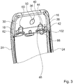
- the carrier element 30 extends between the side frame elements 16, 18 of the load-bearing frame 14.
- the carrier element 30 forms, in particular, connection areas 32, 34 by means of which the carrier element 30 can be firmly connected to the frame 14.
- the carrier element 30 is fixedly connected to a side frame element 16, 18 in the connection areas 32, 34.
- the connection areas 32, 34 of the carrier element 30 are preferably connected in particular to a side of the side frame elements 16, 18 facing a rear side 20 of the backrest unit 12.
- the carrier element 30 is connected to the side frame elements 16, 18 in the connection areas 32, 34, preferably via a form-fit connection.
- the carrier element 30 is preferably connected to the supporting frame 14, in particular the side frame elements 16, 18, in particular by means of a screw or rivet connection.
- the Carrier element 30 is firmly connected to the supporting frame 14 by means of a material connection, such as in particular via an adhesive or welded connection.
- the carrier element 30 is preferably designed in particular as a contour sheet.
- the carrier element 30 preferably has a contour.
- the carrier element 30 In a mounted state, the carrier element 30 is configured to be concave, viewed in a seat direction.
- the carrier element 30 is preferably not designed to be strictly concave. In principle, however, it would be conceivable for the carrier element 30 to be at least essentially strictly concave and to have a continuous curvature between its connecting regions 32, 34.
- the carrier element 30 has a central region 36 between its connecting regions 32, 34. In an assembled state, the central region 36 is arranged between the side frame elements 16, 18 of the load-bearing frame 14. In the middle area 36, the carrier element 30 extends forward in the seat direction, in particular in the direction of the front side 24 of the backrest unit 12.
- the carrier element 30 forms a recess in the middle area 36. Due to the concave design in the central region 36, that is to say the recess, a geometrical moment of inertia of the carrier element 30 is greater than that of a flat design of a carrier element 30, so that the carrier element 30 has particularly advantageous torsional rigidity.
- the carrier element 30 is preferably provided, in particular, to stiffen the backrest unit 12, in particular the supporting frame 14, in the head region 26.
- the backrest unit 12 can be provided with a particularly advantageous torsional rigidity through the carrier element 30.
- the carrier element 30 is preferably provided in particular to absorb tensile forces in an impact.
- the carrier element 30 is provided, in particular, to be at least partially plastically deformed.
- the carrier element 30 is preferably provided so that it does not tear.
- the backrest unit 12, in particular the supporting frame 14, has further transversely extending stiffening elements in other subregions 30.
- the carrier element 30 is preferably at least partially designed as a mounting element.
- the carrier element 30 is provided in particular so that components of the aircraft seat 10 can be mounted thereon.
- About the carrier element 30 are components of the Aircraft seat 10 firmly coupled to the aircraft seat.
- components of the aircraft seat 10 are firmly connected in the head region 26 of the backrest unit 12.
- Components are preferably connected, in particular, to a rear side of the carrier element 30 that is oriented towards the rear and are thus fastened to the aircraft seat 10.
- the carrier element 30 has a mounting area 38.
- the mounting area 38 is preferably arranged at least substantially in the central area 36 of the carrier element 30.
- the assembly area 38 comprises a first connection area 40.
- the first connection area 40 is arranged on a half of the carrier element 30 facing the one side frame element 16 in the head area 26.
- the first connection area 40 is preferably arranged in particular essentially in a center of the half of the carrier element 30 facing the one side frame element 16.
- the first connection area 40 is provided for connection of a functional component.
- the first connection area 40 has fastening elements 42.
- the fastening elements 42 are preferably designed as through holes in the carrier element 30.
- the connection area 40 here has two fastening elements 42, for example. In principle, it is also conceivable that the connection area 40 has a different number of fastening elements 42.
- connection area 40 has more fastening elements 42 than are necessary for fastening a functional component, so that in particular different connection patterns are formed, so that different components can be connected to identically designed carrier elements 30 in the connection area 40 to form different backrest unit variants.
- the connection area 40 forms an assembly contour 44.
- the assembly contour 44 is preferably designed as a recess that forms a defined contour that is provided so that components for a secure and secure connection can at least partially rest thereon, in particular with corresponding support surfaces.
- the connection area 40 comprises a feed-through slot 46.
- the feed-through slot 46 is provided, in particular, so that elements such as cables or other connecting elements can be guided from a front side of the carrier element 30 to a rear side of the carrier element 30.
- a channel can thus advantageously be provided through which, for example, a power supply cable to an in the electrical or electronic functional component arranged in the connection area 40 can be guided particularly easily and directly.
- the assembly area 38 comprises a second connection area 60.
- the second connection area 60 is provided for connecting a functional component.
- the second connection area 60 has fastening elements 62.
- the fastening elements 62 are preferably designed as through holes in the carrier element 30.
- the second connection area 60 is designed essentially the same as the first connection area 40. In principle, it would also be conceivable that the second connection area 60 is configured differently than the first connection area 40, for example in particular differently arranged fastening elements 62, i.e. has a different hole pattern.
- the second connection region 60 is arranged in a half of the carrier element 30 facing the second, right-hand side frame element 18 in the head region 26.
- the second connection area 60 is preferably arranged in particular essentially in a center of the half of the carrier element 30 facing the one side frame element 18.
- the two connection areas 40, 60 are preferably arranged mirror-symmetrically to a vertical center axis of the backrest unit 12 to one another.
- connection areas 40, 60 can be arranged at least partially overlapping.
- the sandwich unit 28 comprises a rigid foam element 48.
- the rigid foam element 48 is preferably designed, in particular, as an impact damping element.
- the rigid foam element 48 is provided, in particular, to absorb impact energy through plastic and / or elastic deformation in the event of an impact.
- the rigid foam element 48 is preferably provided in particular to at least reduce impact forces which, for example, in the event of a crash are introduced into the backrest unit 12 by a head hitting the head area 26 partially absorb.
- the rigid foam element 48 is preferably formed in particular from a PP foam.
- the rigid foam element 48 has a foam density of 50 grams per liter.
- the rigid foam element 48 is designed in particular to be flame-retardant.
- the hard foam element 48 is arranged downstream of the carrier element 30 in the direction of the rear side 20 of the backrest unit 12.
- the rigid foam element 48 is arranged in particular on a rear side 64 of the carrier element 30, which is facing away from the front side 24 of the backrest unit 12.
- the rigid foam element 48 is arranged on a rear side 64 of the carrier element 30 facing away from the covering 22.
- the rigid foam element 48 is preferably arranged in particular in the central region 36.
- the hard foam element 48 is arranged in particular in the recess formed by the carrier element 30.
- the rigid foam element 48 is preferably connected to the carrier element 30 in a form-fitting manner.
- the rigid foam element 48 is preferably connected to the carrier element 30 via a force-fitting and form-fitting connection.
- the carrier element 30 has an assembly opening 50.
- the mounting opening 50 is designed as a through hole.
- the assembly opening 50 is preferably arranged centrally in the carrier element 30.
- the assembly opening 50 forms a form-fit element for connecting the rigid foam element 48.
- the rigid foam element 48 has a form-locking element 52 which, for connection to the carrier element 30, is provided to engage in the assembly opening 50 and preferably to engage behind it.
- the form-fit element 52 of the rigid foam element 48 is designed as an elevation.
- the form-fit element 52 of the rigid foam element 48 is pressed into the assembly opening 50.
- the form-fit element formed from rigid foam is at least partially elastically deformed and thus compressed. If the form-fit element 52 is at least partially guided through the assembly opening 50 during assembly, the corresponding partial area of the form-fit element 52 can expand again and thus engage behind an edge of the assembly opening 50. A form fit can thus be formed between the form fit element 52 of the rigid foam element 48 and the carrier element 30.
- the rigid foam element 48 can advantageously be firmly connected to the carrier element 30.
- the rigid foam element 48 can be fixed particularly advantageously during assembly on the carrier element 30.
- the form-locking element 52 is attached to a front
- the end has an undercut element which, in an assembled state, is provided to engage further behind the carrier element 30.
- the rigid foam element 48 is additionally or only firmly connected to the carrier element 30 by means of an adhesive connection. It is preferably conceivable that the rigid foam element 48 is glued into the recess of the carrier element 30.
- the rigid foam element 48 preferably has a front side 54 facing the carrier element 30 in an assembled state.
- the front side 54 of the rigid foam element 48 is preferably designed to correspond to a contour of the carrier element 30, in particular to correspond to a contour of the central region 36 of the carrier element 30.
- the front side 54 of the rigid foam element 48 rests preferably completely on the rear side 64 of the carrier element 30.
- the hard foam element 48 is arranged with its front side 54 at a distance from the rear side of the carrier element 30 in partial areas.
- the contour of the rigid foam element 48 is preferably adapted to the carrier element 30. Due to its adapted contour, the rigid foam element 48 can preferably only be connected to the carrier element 30 in one orientation. A particularly simple assembly can thereby be achieved.
- the hard foam element 48 has recesses 56, 58.
- the recesses 56, 58 are arranged in particular in areas in which a functional component can be attached to the backrest, in particular in the head area of the backrest unit 12.
- the recesses 56, 58 are preferably made in a rear side 64 of the rigid foam element 48.
- the recesses 56, 58 are preferably designed to be continuous at least in partial areas, that is to say in particular extend as far as the front side 54 of the rigid foam element 48.
- the rigid foam element 48 preferably has the two recesses 56, 58. In principle, it is also conceivable that the rigid foam element 48 has a different number of recesses 56, 58, in particular one corresponds to the components that can possibly be connected to the backrest unit 12.
- the recesses 56, 58 are each arranged in particular in an area of one of the connection areas 40, 60.
- the recesses 56, 58 in the rigid foam element 48 are preferably at least in the Arranged essentially congruently with one of the connection areas 40, 60 of the assembly area 38.
- the first recess 56 is preferably assigned to the first connection area 40 and arranged in its area.
- the second recess 58 is preferably assigned to the second connection area 60 and is arranged in its area.
- the two recesses 56, 58 in the rigid foam element 48 are preferably designed essentially the same. In principle, it would also be conceivable that the two recesses 56, 58 in the rigid foam element 48 are designed differently.
- the recess 56 has a first sub-area 66 in which the connection area 40 has a depth that is smaller than a thickness of the rigid foam element 48, in particular in the corresponding area of the connection area 40.
- the first sub-area 66 of the recess 56 is in particular the rear side 64 of the hard foam element 48 facing.
- the first partial area 66 in particular forms an area in which components that are connected to the carrier element 30 via the corresponding connection area 40 can be at least partially arranged and / or connected.
- the recess 56 preferably forms, in particular, a plateau 68 in the first partial area 66.
- form-fit elements for example in the form of hook elements, can preferably be arranged on the plateau 68, via which components can be at least partially connected to the backrest unit 12.
- the recess 56 has a second partial area 70 in which the recess 56 forms an opening to the front side 54 of the rigid foam element 48.
- the recess 56 extends from the rear side 64 to the front side 54 of the rigid foam element 48.
- the recess 56 is designed as a through hole.
- the second partial area 70 is preferably designed in particular congruent with the connection area 40, in particular congruent with the fastening elements 42.
- the recess 56 has further partial areas in which the recess is designed as a through hole. It is in particular also conceivable that the recess 56 in the other Partial areas only has one through hole which is only provided for the implementation of a connection element, such as in particular a screw or a pin.
- the recess 58 is designed essentially the same as the recess 56 and will therefore not be described in more detail here. The features of the recess 56 can be found in the previous description of the recess 58.
- the sandwich unit 28 preferably has a first insert component 72.
- the sandwich unit 28 preferably has, in particular, a second insert component 74.
- the insert components 72, 74 are designed essentially the same.
- the insert components 72, 74 are provided in particular to be inserted into the recesses 56, 58 of the rigid foam element 48.
- the insert components 72, 74 are provided in particular to be attached in the recesses 56, 58 if no components are attached to the carrier element 30, that is to say the backrest unit 12, via the corresponding connection area 40, 60 arranged behind them.
- the insert components 72, 74 preferably have a shape which essentially corresponds to the shape of the recesses 56, 58.
- the insert components 72, 74 are preferably arranged completely in the corresponding recess 56, 58 in a state arranged in the rigid foam element 48.
- the insert components 72, 74 preferably rest with an inner side on a contour of the corresponding recess 56, 58.
- outer sides of the insert components 72, 74 close the recesses 56, 58 preferably flush with the rear side 64 of the rigid foam element 48.
- the insert components 72, 74 are preferably at least partially materially connected to the rigid foam element 48.
- the insert components 72, 74 are preferably glued to the rigid foam element 48 in defined subregions.
- the insert components 72, 74 are glued into the recesses 56, 58 via an adhesive connection.
- the insert components 72, 74 are glued into the recesses 56, 58 at certain points via one or more adhesive points, or that the insert components 72, 74 are glued into the recesses 56, 58 via a flat adhesive layer.
- the insert components 72, 74 it would also be conceivable for the insert components 72, 74 to be arranged fixedly in the recesses 56, 58 via a force and / or form-fit connection.
- the recesses have form-locking elements, for example in particular hook elements, into which the insert components 72, 74 are integrated
- form-locking elements can engage positively for attachment.
- the two insert components 72, 74 are preferably formed from a foam.
- the insert components 72, 74 are formed from a hard foam.
- the insert components 72, 74 are preferably formed from the same rigid foam as the rigid foam element 48.
- the two insert components 72, 74 form a unit in an assembled state in which they are arranged with the recesses 56, 58 of the rigid foam element 48.
- the insert components 72, 74 form part of the rigid foam element 48.
- the hard foam element 48 is constructed in several parts.
- the backrest unit 12 has at least one cover element 76.
- the cover element 76 at least partially covers the hard foam element 48 on the rear side 20 of the backrest unit 12.
- the cover element 76 is provided in particular to completely cover the hard foam element 48 on the rear side 64.
- the cover element 76 is preferably provided for covering the entire rear side 64 of the backrest unit 12.
- the cover element 76 preferably forms the entire rear side 20 of the backrest unit 12.
- the cover element 76 preferably rests on the hard foam element 48.
- the cover element 76 encloses the rigid foam element 48 between the cover element 76 and the carrier element 30.
- the hard foam element 48 is arranged between the carrier element 30 and the cover element 76.
- the hard foam element 48 is preferably arranged in a positionally secure manner between the carrier element 30 and the cover element 76.
- the cover element 76 preferably rests against the rear side 64 of the rigid foam element 48.
- the cover element 76 is at least partially glued to the rear side 64 of the rigid foam element 48.
- the cover element 76 has different assembly openings 78, 80 in the head area 26 depending on the design and the corresponding components to be attached. Components attached to the backrest unit 12, which are connected to the carrier element 30 via the corresponding connection areas 40, 60, are preferably guided in the assembly openings 78, 80.
- the assembly openings 78, 80 are arranged in particular in the areas of the connection areas 40, 60 of the assembly area 38 of the carrier element 30.
- the mounting openings 78, 80 are congruent with the connection areas 40, 60 of the mounting area 38 of the carrier element 30, and in particular also the recesses 56, 58 arranged in the rigid foam element 48.
- the shape of the assembly openings 78, 80 is designed on the corresponding functional component connected to the backrest. It is conceivable that the assembly openings 78, 80 have more complex geometries that are specially adapted to a geometry of a functional component to be attached, or that the assembly openings 78, 80 are also designed as simple round through holes through which a connecting element, such as in particular a Screw for connection can be passed through.
- the cover element 76 prefferably, it is basically also conceivable for the cover element 76 to have a recess in the area of one of the assembly openings 78, 80 with which the cover element 76 extends at least partially into a corresponding recess 56, 58 of the rigid foam element 48.
- the backrest unit 12 which are at least partially, preferably completely arranged in an interior of the backrest unit 12 in at least one state, preferably a stowed state, and thus in particular not to the rear via the rear side 20 of the cover element 76 formed Protrude from the backrest.
- the cover element 76 has a table recess 84 in a region below the head region 26.
- the backrest unit 12 has a pivotable table element 86 which is arranged in the table recess 84 in a folded-in state. The table element 86 is arranged directly on the rear side of the backrest unit 12 via a pivot bearing.
- the backrest unit 12 has a first functional component 82.
- the first functional component 82 is designed as an electronics connection.
- the functional component has a USB connection.
- the electronics connection has a further connection, such as an audio connection or a completely different connection.
- the functional component 82 is connected to the first connection region 40 on the carrier element 30.
- the functional component 82 is guided through the assembly opening 78 in the cover element 76 and the recess 56 in the hard foam element 48 from the rear side 20 of the backrest unit 12 to the carrier element 30 to which it is attached.
- the functional component 82 is inserted into the recess 56 of the rigid foam element 48 provided for the insert component 72, 74.
- the functional component 82 is at least essentially in the recess 56 of the provided for the insert component 72, 74 Hard foam element 48 arranged.
- a cable 88 of the functional component 82 embodied as an electronic connection is in particular passed through the feed-through slot 46 of the connection area 40 to a front side of the carrier element 30.
- the rigid foam element 48 preferably forms a cable protection element 102 in the region of the feed-through slot 46.
- the cable protection element 102 is designed in particular as an elevation on the front side 54 of the rigid foam element 48.
- the cable protection element 102 embodied as an elevation extends into the feed-through slot 46.
- the cable protection element 102 embodied as an elevation is provided in particular to cover an edge, in particular an edge, of the feed-through slot 46.
- the backrest unit 12 has a second functional component 90.
- the second functional component 90 is designed as a cup holder.
- the functional component 90 embodied as a cup holder is inserted into the recess 58 provided for the insert component 72, 74.
- the functional component 90 is designed as a pivotable cup holder.
- the functional component 90 is guided through the assembly opening 80 in the cover element 76 and the recess 58 in the hard foam element 48 from the rear side 20 of the backrest unit 12 to the carrier element 30 to which it is attached.
- the functional component 90 is inserted into the recess 56 of the rigid foam element 48 provided for the insert component 72, 74.
- the functional component 90 is arranged at least essentially in the recess 56 of the rigid foam element 48 provided for the insert component 72, 74.
- the functional component 90 has a base plate and a holding element, connected to it pivotably, for a beverage element, such as in particular a cup or a can.
- the functional component 90 is connected to the carrier element 30 via the second connection region 60.
- the functional component 90 is firmly connected with its base plate to the fastening elements 62 of the connection area 60.
- the functional component 90 is firmly connected to the connection area 60, in particular via its base plate.
- the functional component 90 In a folded-in state, the functional component 90 is arranged completely in the recess 58 of the rigid foam element 48. In the region of the assembly opening 80, the cover element 76 has a depression which extends into the recess 58.
- the functional component 90 embodied as a pivotable cup holder can in a folded-in state in the recess 58 be arranged and not protrude beyond the rear side 20 of the backrest unit 12.
- the functional component 90 designed as a cup holder In an unfolded state, the functional component 90 designed as a cup holder is partially pivoted out of the recess 58 of the rigid foam element 48.
- a backrest unit 12 can be provided which, in the head region 26, has particularly advantageous properties for a head impact in the event of a crash, in particular also independently of a configuration.
- the same rigid foam element 48 and the same carrier element 30 can be used for different configurations with different functional components 82, 90.
- the insert component 72 is removed from the recess 56, or no insert component 72, 74 is inserted into the recess 56 and the corresponding functional component 82, 90 is inserted the recess 56 is inserted, while an insert component 74 is inserted into the recess 58 in which no functional component 82, 90 is to be arranged, or, accordingly, is not removed from the recess 58.
- a functional component 82, 90 would be arranged in particular in the first recess 56 of the rigid foam element 48 and the corresponding insert component 72, 74 in the second recess 58 of the rigid foam element 48.
- an advantageous impact surface can be created.
- a functional component 82, 90 built into the hard foam element 48 preferably has a stiffness that differs from an insert component 72, 74 built into the hard foam element 48 by a maximum of 2%.
- the different variations of the backrest unit 12 preferably always have the same impact characteristics, which means that crash tests are preferably carried out with only one Configuration of the backrest unit 12 for the approval of backrest units 12 with different configurations are sufficient.
- the backrest unit 12 does not have any functional components 82, 90 arranged in its head region 26.
- a corresponding insert component 72, 74 would be arranged in each of the two recesses 56, 58 of the rigid foam element 48.
- the backrest unit 12 it would also be conceivable for the backrest unit 12 to have at least partially a literature pocket 104 in its head area 26, which extends in an area between the carrier element 30 and the cover element 76 in the backrest unit 12.
- the literature pocket 104 has an opening 106 which is located in an upper edge region of the head region 26, in particular above possible functional components 82, 90.
- a literature pocket 104 is at least partially formed by a cavity in the rigid foam element 48.
- a backrest unit 12 with another functional component 92 is shown.
- the functional component 92 is designed in particular as a display unit which is provided to connect display elements, such as in particular flyers or advertising prints, to the backrest unit 12.
- the functional component 92 has a frame 94 which surrounds a display area.
- the functional component 92 comprises a transparent cover element 96, which is designed in particular as a Plexiglas pane or a transparent plastic element.
- the cover element 96 can be attached to the frame 94 and covers the display area.
- a thin element, such as in particular a sheet of paper or a film, can be arranged behind the cover element 96.
- the frame 94 of the functional component 92 is preferably connected to the carrier element 30 via both connection areas 40, 60 of the assembly area 38 or to the backrest unit 12 via the cover element 76 itself.
- a screen unit is arranged in the frame.
- a display film in particular, is arranged in the frame 94 of the functional component 92.
- a connection cable of the display film can preferably, in particular, pass through an assembly opening in the cover element 76 and a corresponding recess 54, 56 in the Hard foam element 48 and the feed-through slot 46 are guided in a connection area 40, 60.
- Figure 9 shows an alternative embodiment of the rigid foam element 48 and the insert components 72, 74 introduced therein.
- the recesses 56, 58 of the rigid foam element 48 are connected to one another via a connecting region 98.
- the connection area 98 is also designed as a recess.
- the recesses 56, 58 and the connecting area 98 together result in a contiguous recess.
- the two insert components 72, 74 are connected to one another in one piece via a web 100.
- the web 100 is designed in accordance with the connecting region 98 designed as a recess.
- the web 100 can be inserted into the connection area 98 in the rigid foam element 48.
- the two insert components 72, 74 together with the web 100 form a component which can be inserted together into the recesses 56, 58 and the connecting area 98. If a functional component 82, 90 is to be inserted into one of the recesses 56, 58 of the rigid foam element 48, one corresponding insert component 72, 74 is broken off from the web 100 and only the other insert component 72, 74 with the web 100 into the corresponding recess 56 , 58 and the connection area 98 used.
- the carrier element 30 is formed by a flexible component, in particular a fabric and / or a film.
- the rigid foam element 48 is preferably provided, in particular, to provide stability for the sandwich unit 28.
- the flexible carrier element 30 is preferably provided in particular to absorb tensile forces in the event of a crash, in particular in the event of a deformation.
- the flexible carrier element 30 is designed in particular as an insert in the hard foam element 48.
- the hard foam element 48 extends on both sides of the carrier element 30.
- the hard foam element 48 at least substantially surrounds the carrier element 30. Only connection areas 32, 43 of the carrier element 30 preferably protrude laterally out of the rigid foam element 48.
- the carrier element 30 is preferably a fabric made of fibers, for example made of carbon fibers, which are soaked at least in side areas, in particular in the connecting areas, with a hard resin and hardener and thereby in particular there are at least partially rigid.
- a central area in which the fabric is arranged in the hard foam element 48 it is conceivable that the fibers are in particular not soaked in a hard resin and hardener and are therefore particularly limp there.
- the carrier element 30 it would also be particularly conceivable for the carrier element 30 to be formed by a coating on the rigid foam element 48.
- a partial area of the rigid foam element 48 arranged in front of the carrier element 30 extends to directly in front of the covering 22 and can at least partially form a cushion for a head support area of the backrest unit 12.
- the backrest unit 12 does not have a cover element 76 in the head region 26 on the rear side 64, but that the rear side 20 of the backrest unit 12 is formed by a coating of the hard foam element 48.
- the backrest unit 12 does not have any covering 22 in the head region 26.
- a head support area is formed by the forwardly extending part of the rigid foam element 48.
- the front side of the rigid foam element 48 can preferably form a headrest contour.
- a soft foam element with a cover could preferably be arranged on the front side of the rigid foam element 48 in order to form the head support surface.
Landscapes
- Engineering & Computer Science (AREA)
- Aviation & Aerospace Engineering (AREA)
- Transportation (AREA)
- Mechanical Engineering (AREA)
- Seats For Vehicles (AREA)
- Chair Legs, Seat Parts, And Backrests (AREA)
Abstract
Description
- Die Erfindung betrifft eine Flugzeugsitzvorrichtung.
- Es ist bereits eine Flugzeugsitzvorrichtung mit einer Rückenlehneneinheit, die einen Kopfbereich aufweist, vorgeschlagen worden.
- Die Aufgabe der Erfindung besteht insbesondere darin, eine gattungsgemäße Vorrichtung mit verbesserten Eigenschaften hinsichtlich einer Sicherheit und einer Modularität bereitzustellen. Die Aufgabe wird erfindungsgemäß durch die Merkmale des Patentanspruchs 1 gelöst, während vorteilhafte Ausgestaltungen und Weiterbildungen der Erfindung den Unteransprüchen entnommen werden können.
- Erfindungsgemäß wird eine Flugzeugsitzvorrichtung, mit einer Rückenlehneneinheit, die einen Kopfbereich mit zumindest einer Sandwicheinheit umfasst, die zumindest ein Trägerelement und in Richtung einer Rückseite der Rückenlehneneinheit zumindest ein dem Trägerelement nachgeordnetes Aufpralldämpfungselement, insbesondere ein Hartschaumelement aufweist, vorgeschlagen. Unter einer "Flugzeugsitzvorrichtung" soll insbesondere eine Vorrichtung verstanden werden, die zumindest einen Teil, oder einen kompletten Flugzeugsitz ausbildet. Unter einem "Flugzeugsitz" soll vorzugsweise ein Sitz, insbesondere ein Fluggastsitz, verstanden werden, der dazu vorgesehen ist, über eine Aufständereinheit in einer Flugzeugkabine aufgeständert zu werden und einen Sitzplatz für einen Passagier, insbesondere während eines Flugs, bereitzustellen. Der Flugzeugsitz weist vorzugsweise zumindest eine Sitzbodeneinheit, eine Rückenlehneneinheit und eine Armlehneneinheit auf, die vorzugsweise über die Aufständereinheit angebunden sind. Unter einer "Rückenlehneneinheit" soll dabei insbesondere eine Einheit verstanden werden, die zumindest einen Teil einer Rückenlehne eines Flugzeugsitzes, ausbildet, wobei die Rückenlehneneinheit zumindest einen tragenden Rahmen umfasst, der in sich steif ausgebildet und insbesondere dazu vorgesehen ist, in die Rückenlehneneinheit eingeleitete Kräfte an eine Aufständereinheit des Flugzeugsitzes weiterzuleiten, sodass diese Kräfte insbesondere in einen Kabinenboden, auf dem der Flugzeugsitz aufgeständert ist, abgeleitet werden können. Unter einem "Kopfbereich" soll insbesondere ein oberer Bereich der Rückenlehneneinheit verstanden werden. Vorzugsweise ist der Kopfbereich in den oberen 30 cm der Rückenlehneneinheit angeordnet. Vorzugsweise ist der Kopfbereich insbesondere als ein Teil ausgebildet, in dem in einem Crashfall ein Kopf eines hinter dem Flugzeugsitz sitzenden Passagiers auf die Rückenlehneneinheit auftreffen würde. Unter einer "Sandwicheinheit" soll insbesondere eine Einheit aus zumindest zwei, vorzugsweise drei miteinander verbunden Elementen verstanden werden. Unter einem "Trägerelement" soll insbesondere ein Element verstanden werden, das dazu vorgesehen ist, eine Grundstruktur auszubilden, mit der andere Elemente verbunden werden können, wobei insbesondere Kräfte über das Trägerelement in einen Rahmen, insbesondere einen Rahmen der Rückenlehneneinheit abgeleitet werden können. Vorzugsweise ist das Trägerelement insbesondere als eine Platte ausgebildet. Vorzugsweise ist das Trägerelement als eine Metallplatte oder eine Platte aus einem Composite oder einem Kunststoff gebildet. Das Trägerelement ist insbesondere dazu vorgesehen, dass Bauteile, insbesondere Funktionsbauteile über das Trägerelement an die Rückenlehne angebunden werden können. Zur Anbindung von weiteren Elementen weist das Trägerelement vorzugsweise insbesondere einen Montagebereich auf, in dem das Trägerelement Befestigungselemente, wie insbesondere Durchgangslöcher oder andere Formschlusselemente aufweist. Unter einem "Aufpralldämpfungselement" soll insbesondere ein Element verstanden werden, das dazu vorgesehen ist, im Fall eines Aufpralls von einem Element, wie beispielsweise insbesondere einem Kopf eines Passagiers, eine Aufprallenergie aufzunehmen und umzuwandeln. Vorzugsweise ist das Aufpralldämpfungselement insbesondere durch plastische und elastische Verformung dazu vorgesehen, eine Aufprallenergie umzuwandeln und so einen Aufprall zu dämpfen. Das Aufpralldämpfungselement kann dabei vorzugsweise insbesondere aus einem Schaum, insbesondere einem Partikelschaum, gebildet sein, oder in einer anderen Ausgestaltung, beispielsweise auch aus einem Wabenelement, einem anderen Schaum, oder einem anderen Element mit einer entsprechenden Raumdichte. Unter einem "Hartschaumelement" soll vorzugsweise insbesondere ein Partikelschauelement verstanden werden, das zumindest im Wesentlichen aus einem Partikelschaum gebildet ist. Unter einem "Hartschaumelement" soll insbesondere ein Element verstanden werden, das zumindest zu über 50 %, vorzugsweise zu zumindest 80% und besonders bevorzugt zu 100 % aus einem Schaum, insbesondere einem Hartschaum gebildet ist. Unter einem Hartschaum soll insbesondere ein PP-Schaum verstanden werden. Das Hartschaumelement ist vorzugsweise insbesondere aus einem PP-Schaum (Polypropylen Schaum) gebildet. Das Hartschaumelement weist vorzugsweise eine Schaumdichte von 30 - 70 Gramm pro Liter, vorzugsweise insbesondere eine Schaumdichte von 40 - 60 Gramm pro Liter auf. Vorzugsweise ist das Hartschaumelement flammhemmend ausgebildet. Das Hartschaumelement ist insbesondere schwer entflammbar. Unter "vorgesehen" soll insbesondere speziell ausgelegt und/oder ausgestattet verstanden werden. Darunter, dass ein Objekt zu einer bestimmten Funktion vorgesehen ist, soll insbesondere verstanden werden, dass das Objekt diese bestimmte Funktion in zumindest einem Anwendungs- und/oder Betriebszustand erfüllt und/oder ausführt. Durch eine erfindungsgemäße Ausgestaltung kann vorteilhaft eine Rückenlehneneinheit bereitgestellt werden, die besonders sicher ausgebildet ist. Durch das Hartschaumelement kann in einem Crashfall ein Aufprall eines Kopfes eines Passagiers, der auf einem hinter der Rückenlehneneinheit angeordneten Flugzeugsitz sitzt, auf der Rückenlehneneinheit besonders vorteilhaft abgedämpft werden.
- Weiter wird vorgeschlagen, dass das Trägerelement dazu vorgesehen ist, in einem Aufprall Kräfte aufzunehmen. Unter einem "Aufprall" soll insbesondere ein Aufprall eines Kopfes eines Passagiers, oder im Falle eines Crashtests, der Kopf eines Crashtestdummys auf der Rückenlehneneinheit verstanden werden. Unter "Kräfte aufnehmen" soll insbesondere verstanden werden, dass das Trägerelement durch plastische und/oder elastische Verformung Kräfte, wie insbesondere Zug-, Druck- und oder Torsionskräfte, aufnehmen und zumindest teilweise umwandeln kann. Dadurch kann das Trägerelement besonders vorteilhaft für einen Crashfall ausgebildet werden.
- Ferner wird vorgeschlagen, dass das Trägerelement von einem Plattenelement gebildet ist. Unter einem "Plattenelement" soll insbesondere ein Element verstanden werden, das eine dünne Wandstärke aufweist. Ein Plattenelement ist vorzugsweise insbesondere als ein flächiges Element ausgebildet, das vorzugsweise insbesondere eine im Vergleich zu seiner Erstreckung in zwei Raumrichtungen dünne Wandstärke aufweist. Dadurch kann das Trägerelement besonders vorteilhaft ausgebildet werden.
- Es wird weiterhin vorgeschlagen, dass das Trägerelement von einem biegeweichen Bauteil, insbesondere von einem Gewebe und/oder einer Folie gebildet ist. Ist das Trägerelement von einem biegeweichen Bauteil gebildet, so ist das Trägerelement vorzugsweise beidseitig, also auf einer Vorderseite, als auch auf einer Rückseite von dem Hartschaumelement umgeben. Das biegeweiche Trägerelement ist vorzugsweise insbesondere als ein Einleger in dem Hartschaumelement ausgebildet. Das Trägerelement kann vorzugsweise insbesondere als Einleger ausgebildet sein, der in das Hartschaumelement eingeschäumt ist. Das Trägerelement bildet zusammen mit dem Hartschaumelement ein Verbund aus. Dadurch kann das Trägerelement vorzugsweise besonders leicht, also mit einem geringen Gewicht ausgebildet werden.
- Des Weiteren wird vorgeschlagen, dass das Trägerelement in einer weiteren Ausführung von einer Beschichtung des Hartschaumelements gebildet ist. Unter einer "Beschichtung" soll insbesondere eine auf eine Oberfläche vorzugsweise dünn aufgebrachte Schicht verstanden werden, die vorzugsweise zum Schutz des darunter liegenden Bauteils, oder zur Verschönerung des Bauteils vorgesehen ist. Grundsätzlich ist es auch denkbar, dass die Beschichtung so ausgebildet ist, dass diese Kräfte übertragen kann und so zumindest teilweise als ein Trägerelement ausgebildet werden kann. Dadurch kann das Trägerelement besonders einfach und leicht ausgebildet werden.
- Weiterhin wird vorgeschlagen, dass das Trägerelement in einer Sitzrichtung betrachtet zumindest teilweise im Wesentlichen konkav ausgebildet ist. Unter "im Wesentlichen konkav" soll insbesondere verstanden werden, dass ein Bauteil, wie insbesondere das Trägerelement in seiner Gesamtheit konkav ausgebildet ist. Das Trägerelement ist vorzugsweise insbesondere nicht streng konkav ausgebildet. Unter "in Sitzrichtung betrachtet" soll vorzugsweise in einem montierten Zustand in Sitzrichtung betrachtet verstanden werden. Unter einer "Sitzrichtung" soll vorzugsweise insbesondere eine Richtung verstanden werden, die in einem montierten Zustand des Flugzeugsitzes im Wesentlichen senkrecht auf einer Rückenlehnenfläche der Rückenlehneneinheit steht und vorzugsweise insbesondere im Wesentlichen parallel zu einer Aufständerebene, auf der der Flugzeugsitz aufgeständert ist, ausgerichtet ist. Dadurch weist das Trägerelement ein besonderes vorteilhaftes Flächenträgheitsmoment auf und kann dadurch bei einem geringen Gewicht vorteilhaft biegesteif ausgebildet werden.
- Außerdem wird vorgeschlagen, dass das Hartschaumelement zumindest eine Ausnehmung für ein Einsatzbauteil und/oder ein Funktionsbauteil aufweist. Unter einem "Einsatzbauteil" soll insbesondere ein Bauteil verstanden werden, das dazu vorgesehen ist, in eine Ausnehmung eingesetzt zu werden, um diese insbesondere bei Nichtgebrauch zu verschließen und vorzugsweise zumindest im Wesentlichen auszufüllen. Das Einsatzbauteil weist auf einer Seite vorzugsweise zumindest im Wesentlichen eine gleiche Kontur auf wie die Ausnehmung, in der es angeordnet sein soll. Vorzugsweise schließt ein Einsatzbauteil eine Ausnehmung, in der es angeordnet ist, ebenbündig ab. Dadurch kann das Hartschaumelement besonders vorteilhaft zur Anbindung von Funktionselementen an die Rückenlehneneinheit ausgebildet werden.
- Es wird weiter vorgeschlagen, dass die Sandwicheinheit zumindest ein Einsatzbauteil aufweist, das zumindest teilweise in der Ausnehmung aufgenommen ist. Unter "zumindest teilweise in der Ausnehmung aufgenommen" soll insbesondere verstanden werden, dass zumindest ein Teil, vorzugsweise zumindest 70%, vorzugsweise 90% und in einer besonders vorteilhaften Ausgestaltung das gesamte Einsatzbauteil in der Ausnehmung angeordnet ist. Dadurch kann eine nicht gebrauchte Ausnehmung vorzugsweise verschlossen werden und eine Steifigkeit des Hartschaumelements im Gegensatz zu einem Zustand in dem kein Einsatzbauteil in der Ausnehmung angeordnet ist, vorteilhaft erhöht werden.
- Zudem wird vorgeschlagen, dass das wenigstens eine Einsatzbauteil zumindest teilweise mit dem Hartschaumelement stoffschlüssig verbunden ist. Unter "stoffschlüssig verbunden" soll insbesondere mittels einer stoffschlüssigen Verbindung, wie insbesondere einer Klebeverbindung verbunden, oder einstückig ausgestaltet verstanden werden. Dadurch kann das Einsatzbauteil besonders vorteilhaft in dem Hartschaumelement angeordnet werden.
- Weiter wird vorgeschlagen, dass das Hartschaumelement mehrteilig ausgebildet ist. Dadurch kann das Hartschaumelement besonders vorteilhaft ausgebildet werden, insbesondere zusammen mit dem Einsatzbauteil.
- Ferner wird vorgeschlagen, dass die Flugzeugsitzvorrichtung zumindest ein Abdeckelement aufweist, das das Hartschaumelement auf der Rückseite der Rückenlehneneinheit zumindest teilweise abdeckt. Unter einem "Abdeckelement" soll insbesondere ein Element verstanden werden, das ein weiteres Element, wie insbesondere das Hartschaumelement in eine Richtung abschließt, um ein Bauteil, wie insbesondere die Rückenlehneneinheit abzuschließen. Das Abdeckelement ist vorzugsweise insbesondere aus einem formstabilen Kunststoff oder Composite gebildet. Vorzugsweise ist es auch denkbar, dass das Abdeckelement stoffschlüssig mit dem Hartschaumelement verbunden ist und beispielsweise durch eine Klebeverbindung mit dem Hartschaumelement verbunden ist, oder bei einem Herstellverfahren an das Hartschaumelement angespritzt ist. Unter "zumindest teilweise abdeckt" soll insbesondere verstanden werden, dass zumindest ein Teil des Hartschaumelements von dem Abdeckelement in zumindest eine Richtung überdeckt wird, wobei vorzugsweise ein Hauptteil und besonders vorteilhaft das gesamte Hartschaumelement überdeckt wird. Vorzugsweise ist das Abdeckelement dazu vorgesehen, die gesamte Rückenlehneneinheit nach hinten zu überdecken und damit nach hinten abzuschließen. Dadurch kann die Rückenlehneneinheit zumindest im Kopfbereich vorteilhaft nach hinten abgedeckt und abgeschlossen werden.
- Es wird weiterhin vorgeschlagen, dass die Flugzeugsitzvorrichtung zumindest ein Funktionsbauteil aufweist, das dazu vorgesehen ist, in die für das Einsatzbauteil vorgesehene Ausnehmung des Hartschaumelements eingesetzt zu werden. Unter einem "Funktionsbauteil" soll insbesondere ein Bauteil verstanden werden, dass an der Rückenlehneneinheit angebracht werden kann und insbesondere eine Funktion für einen Passagier, insbesondere für einen hinter dem Flugzeugsitz, der die Rückenlehneneinheit aufweist, sitzenden Passagier bereitstellt. Das Funktionselement kann vorzugsweise insbesondere als ein Getränkehalter, als ein Elektronikanschluss, als ein Tablethalter, als ein Handyhalter, als eine Aufbewahrungsbox, als eine Anzeigeeinheit, oder als ein anderes, dem Fachmann als sinnvoll erscheinendes Bauteil ausgebildet sein. Dadurch kann die Rückenlehneneinheit besonders vorteilhaft ausgebildet werden und insbesondere Funktionen für einen Passagier aufweisen.
- Des Weiteren wird vorgeschlagen, dass das Funktionsbauteil in einem in dem Hartschaumelement eingebauten Zustand eine Steifigkeit aufweist, die sich von einer Steifigkeit des Einsatzbauteils in einem in dem Hartschaumelement eingebauten Zustand um maximal 10%, vorzugsweise maximal 5% und besonders bevorzugt um maximal 2% unterscheidet. Dadurch kann vorteilhaft erreicht werden, dass für einen Flugzeugsitz mit einer Rückenlehneneinheit mit unterschiedlichen Konfigurationen im Kopfbereich lediglich ein Crashtest durchgeführt werden muss, wodurch insbesondere Kosten bei einer Zulassung gespart werden können.
- Die erfindungsgemäße Flugzeugsitzvorrichtung soll hierbei nicht auf die oben beschriebene Anwendung und Ausführungsform beschränkt sein. Insbesondere kann die erfindungsgemäße Flugzeugsitzvorrichtung zu einer Erfüllung einer hierin beschriebenen Funktionsweise eine von einer hierin genannten Anzahl von einzelnen Elementen, Bauteilen und Einheiten abweichende Anzahl aufweisen.
- Weitere Vorteile ergeben sich aus der folgenden Zeichnungsbeschreibung. In den Zeichnungen ist ein Ausführungsbeispiel der Erfindung dargestellt. Die Zeichnungen, die Beschreibung und die Ansprüche enthalten zahlreiche Merkmale in Kombination. Der Fachmann wird die Merkmale zweckmäßigerweise auch einzeln betrachten und zu sinnvollen weiteren Kombinationen zusammenfassen.
- Es zeigen:
- Fig. 1
- eine schematische Darstellung einer erfindungsgemäßen Flugzeugsitzvorrichtung mit einer Rückenlehneneinheit und einer Sandwicheinheit, wobei eine Abdeckeinheit lediglich zur Hälfte dargestellt ist,
- Fig. 2
- eine schematische Darstellung der Rückenlehneneinheit von hinten mit zwei Funktionsbauteilen,
- Fig. 3
- eine schematische Darstellung eines Teils einer nicht komplett montierten Rückenlehneneinheit mit einem Rahmen und einem daran im Kopfbereich befestigten Trägerelement,
- Fig. 4
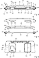
- einen schematischen Horizontalschnitt durch die Rückenlehneneinheit im Kopfbereich,
- Fig. 5
- eine Explosionsdarstellung des Horizontalschnitts der
Figur 4 , - Fig. 6
- eine schematische Frontansicht eines Hartschaumelements der Sandwicheinheit,
- Fig. 7
- einen schematischen seitlichen Vertikalschnitt durch die Rückenlehneneinheit,
- Fig. 8
- eine schematische Darstellung einer Rückenlehneneinheit mit einem anderen Funktionsbauteil,
- Fig. 9
- eine schematische Darstellung einer anderen Ausgestaltung des Hartschaumelements mit Einsatzbauteilen,
- Fig. 10
- eine schematische Schnittansicht durch eine Sandwicheinheit in einer Ausführungsform mit einem biegeweichen Trägerelement, das von einem Hartschaumkern zumindest im Wesentlichen umgeben ist.
- Die
Figuren 1 bis 10 zeigen eine erfindungsgemäße Flugzeugsitzvorrichtung. Die Flugzeugsitzvorrichtung ist Teil eines teilweise dargestellten Flugzeugsitzes 10. Der Flugzeugsitz 10 ist vorzugsweise als ein Economy-Flugzeugsitz ausgebildet. Der Flugzeugsitz 10 ist vorzugsweise als ein Teil einer Sitzreihe mit mehreren Flugzeugsitzen ausgebildet. Der Flugzeugsitz 10 ist dazu vorgesehen, in einer Flugzeugkabine angeordnet zu werden. Der Flugzeugsitz 10 weist vorzugsweise eine nicht näher dargestellte Aufständereinheit auf, mittels der der Flugzeugsitz 10 auf einem Kabinenboden der Flugzeugkabine aufständerbar ist. Vorzugsweise ist die Aufständereinheit insbesondere dazu vorgesehen, Flugzeugsitze 10 einer Flugzeugsitzreihe zusammen auf dem Kabinenboden aufzustützen. Der Flugzeugsitz 10 umfasst eine nicht näher dargestellte Sitzbodeneinheit. Die Sitzbodeneinheit ist dazu vorgesehen, eine Sitzfläche des Flugzeugsitzes 10 auszubilden. Die Sitzbodeneinheit ist vorzugsweise mit der Aufständereinheit gekoppelt. Die Flugzeugsitzvorrichtung umfasst eine Rückenlehneneinheit 12. Die Rückenlehneneinheit 12 bildet vorzugsweise eine Rückenlehneneinheit 12 des Flugzeugsitzes 10 aus. Die Rückenlehneneinheit 12 ist vorzugsweise über die Aufständereinheit an den Flugzeugsitz 10 angebunden. Die Rückenlehneneinheit 12 ist vorzugsweise dazu vorgesehen, verschwenkbar mit der Aufständereinheit verbunden zu sein. Vorzugsweise ist die Rückenlehneneinheit 12 zwischen einer aufrechten Sitzstellung und einer nach hinten geneigten Komfortstellung verschwenkbar. Grundsätzlich ist es auch denkbar, dass die Rückenlehneneinheit 12 starr mit der Aufständereinheit verbunden ist und nicht für eine Winkelverstellung, insbesondere während einer Benutzung vorgesehen ist. - Die Rückenlehneneinheit 12 umfasst vorzugsweise einen tragenden Rahmen 14. Der tragende Rahmen 14 ist dazu vorgesehen, in die Rückenlehneneinheit 12 eingeleitete Kräfte, die insbesondere während eines Gebrauchs des Flugzeugsitzes 10 auf die Rückenlehneneinheit 12 wirken, in die Aufständereinheit weiter- und abzuleiten. Der tragende Rahmen 14 ist vorzugsweise insbesondere in sich steif ausgebildet und dazu vorgesehen, ein Torsionsmoment übertragen zu können. Der tragende Rahmen 14 ist dabei aus einem Metallprofil gebildet. Der tragende Rahmen 14 ist vorzugsweise insbesondere aus einem Profilelement, vorzugsweise insbesondere als ein Metallprofil ausgebildet. Der tragende Rahmen 14 ist vorzugsweise aus einer Aluminiumlegierung gebildet. Grundsätzlich ist es auch denkbar, dass der tragende Rahmen 14 aus einem anderen Metall, wie beispielsweise aus einer Magnesiumlegierung, oder einer Titanlegierung gebildet ist. Grundsätzlich ist es ebenso denkbar, dass der tragende Rahmen 14 aus einem anderen, dem Fachmann als sinnvoll erscheinenden Material gebildet ist, wie insbesondere einem Faserverbundwerkstoff, wie insbesondere einem CFK oder einem GFK. Der tragende Rahmen 14 der Rückenlehneneinheit 12 bildet eine im Wesentlichen U-förmige Grundform aus. Vorzugsweise ist der tragende Rahmen 14 in einem montierten Zustand nach unten, in Richtung der Aufständereinheit geöffnet. An einem oberen Ende, das in einem montierten Zustand der Aufständereinheit abgewandt ist, ist der tragende Rahmen 14 geschlossen ausgebildet. Der tragende Rahmen 14 weist zwei Seitenrahmenelemente 16, 18 auf. Die Seitenrahmenelemente 16, 18 bilden den tragenden Rahmen 14 seitlich aus. Die beiden Seitenrahmenelemente 16, 18 sind in einem oberen Ende zur Ausbildung des im Wesentlichen U-förmigen Rahmens 14 miteinander verbunden. Die beiden Seitenrahmenelemente 16, 18 sind vorzugsweise einstückig miteinander ausgebildet. Grundsätzlich ist es auch denkbar, dass die Seitenrahmenelemente 16, 18 als separat ausgebildete Einzelteile ausgebildet sind, die an ihren oberen Enden direkt oder über ein Zwischenelement miteinander gekoppelt sind. An ihren unteren Enden, die der Aufständereinheit zugewandt sind, sind die Seitenrahmenelemente 16, 18 jeweils fest mit der Aufständereinheit gekoppelt. Vorzugsweise sind die Seitenrahmenelemente 16, 18 jeweils über ein Schwenklager drehbar mit Sitzteilern der Aufständereinheit gekoppelt. Grundsätzlich ist es vorzugsweise auch denkbar, dass die Rückenlehneneinheit 12 starr mit der Aufständereinheit gekoppelt ist und die Seitenrahmenelemente 16, 18 dazu jeweils in einer definierten Position fixiert an der Aufständereinheit angebunden sind.
- Die Rückenlehneneinheit 12 weist eine Bespannung 22 auf, die die Rückenlehnenfläche ausbildet. Die Bespannung 22 ist vorzugsweise von einem Textil gebildet. Die Bespannung 22 ist in den tragenden Rahmen 14 der Rückenlehneneinheit 12 eingespannt ist. Die Bespannung 22 ist auf einer Vorderseite 24 der Rückenlehneneinheit 12 angeordnet. Eine in Sitzrichtung nach vorne gewandte Seite der Bespannung 22 bildet dabei die Rückenlehnenfläche der Rückenlehneneinheit 12 aus. Auf der Bespannung 22 kann vorzugsweise in einem montierten Zustand eine nicht näher dargestellte Polstereinheit angebracht sein.
- An einem oberen Ende bildet die Rückenlehneneinheit 12 einen Kopfbereich 26 aus. Die Rückenlehneneinheit 12 weist eine Sandwicheinheit 28 auf. Die Sandwicheinheit 28 ist in dem Kopfbereich 26 der Rückenlehneneinheit 12 angeordnet. Die Sandwicheinheit 28 ist vorzugsweise fest mit dem tragenden Rahmen 14 verbunden. Die Sandwicheinheit 28 ist in dem Kopfbereich 26 vorzugsweise zwischen den Seitenrahmenelementen 16, 18 angeordnet. Die Sandwicheinheit 28 ist vorzugsweise starr mit dem tragenden Rahmen 14, insbesondere mit den Seitenrahmenelementen 16, 18 des Rahmens 14 der Rückenlehneneinheit 12 verbunden. Die Sandwicheinheit 28 umfasst ein Trägerelement 30. Das Trägerelement 30 ist als ein Plattenelement ausgebildet. Vorzugsweise ist das Trägerelement 30 insbesondere von einer Metallplatte gebildet. Grundsätzlich ist es auch denkbar, dass das Trägerelement 30 aus einem anderen, dem Fachmann als sinnvoll erscheinenden Material gebildet ist, wie insbesondere beispielsweise einem Faserverbundwerkstoff, oder einem Kunststoff. Das Trägerelement 30 erstreckt sich in einem montierten Zustand zwischen den Seitenrahmenelementen 16, 18 des tragenden Rahmens 14. Das Trägerelement 30 bildet in seinen Seitenbereichen insbesondere Verbindungsbereiche 32, 34 auf, mittels denen das Trägerelement 30 fest mit dem Rahmen 14 verbindbar ist. Das Trägerelement 30 ist in den Verbindungsbereichen 32, 34 jeweils fest mit einem Seitenrahmenelement 16, 18 verbunden. Die Verbindungsbereiche 32, 34 des Trägerelements 30 sind vorzugsweise insbesondere auf einer einer Rückseite 20 der Rückenlehneneinheit 12 zugewandten Seite der Seitenrahmenelemente 16, 18 angebunden. Das Trägerelement 30 ist in den Verbindungsbereichen 32, 34 vorzugsweise über eine Formschlussverbindung mit den Seitenrahmenelementen 16, 18 verbunden. Das Trägerelement 30 ist vorzugsweise insbesondere mittels einer Schraub- oder Nietverbindung mit dem tragenden Rahmen 14, insbesondere den Seitenrahmenelementen 16, 18 verbunden. Grundsätzlich ist es auch denkbar, dass das Trägerelement 30 mittels einer stoffschlüssigen Verbindung fest mit dem tragenden Rahmen 14 verbunden ist, wie beispielsweise insbesondere über eine Klebe- oder Schweißverbindung.
- Das Trägerelement 30 ist vorzugsweise insbesondere als ein Konturblech ausgebildet. Das Trägerelement 30 weist vorzugsweise eine Kontur auf. Das Trägerelement 30 ist in einem montierten Zustand in einer Sitzrichtung betrachtet konkav ausgestaltet. Vorzugsweise ist das Trägerelement 30 nicht streng konkav ausgebildet. Grundsätzlich wäre es aber denkbar, dass das Trägerelement 30 zumindest im Wesentlichen streng konkav ausgebildet und zwischen seinen Verbindungsbereichen 32, 34 eine durchgehende Krümmung aufweist. Das Trägerelement 30 weist zwischen seinen Verbindungsbereichen 32, 34 einen Mittelbereich 36 auf. Der Mittelbereich 36 ist in einem montierten Zustand zwischen den Seitenrahmenelementen 16, 18 des tragenden Rahmens 14 angeordnet. In dem Mittelbereich 36 erstreckt sich das Trägerelement 30 in Sitzrichtung nach vorne, insbesondere in Richtung der Vorderseite 24 der Rückenlehneneinheit 12. Das Trägerelement 30 bildet in dem Mittelbereich 36 eine Vertiefung aus. Durch die konkave Ausbildung in dem Mittelbereich 36, also durch die Vertiefung ist ein Flächenträgheitsmoment des Trägerelements 30 im Vergleich zu einer ebenen Ausbildung eines Trägerelements 30 größer, sodass das Trägerelement 30 eine besonders vorteilhafte Torsionssteifigkeit aufweist. Das Trägerelement 30 ist vorzugsweise insbesondere dazu vorgesehen, die Rückenlehneneinheit 12, insbesondere den tragenden Rahmen 14 in dem Kopfbereich 26 auszusteifen. Durch das Trägerelement 30 kann die Rückenlehneneinheit 12 mit einer besonders vorteilhaften Torsionssteifigkeit bereitgestellt werden. Das Trägerelement 30 ist vorzugsweise insbesondere dazu vorgesehen ist, in einem Aufprall Zugkräfte aufzunehmen. Das Trägerelement 30 ist zur Aufnahme von Zugkräften bei einem Aufprall insbesondere dazu vorgesehen, zumindest teilweise plastisch verformt zu werden. Vorzugsweise ist das Trägerelement 30 dazu vorgesehen, nicht zu reißen. Grundsätzlich ist es denkbar, dass die Rückenlehneneinheit 12, insbesondere der tragende Rahmen 14 in anderen Teilbereichen 30 weitere querverlaufende Versteifungselemente aufweist.
- Das Trägerelement 30 ist vorzugsweise zumindest teilweise als ein Montageelement ausgebildet. Das Trägerelement 30 ist insbesondere dazu vorgesehen, dass Bauteile des Flugzeugsitzes 10 daran montierbar sind. Über das Trägerelement 30 sind Bauteile des Flugzeugsitzes 10 fest mit dem Flugzugsitz gekoppelt. Mittels dem Trägerelement 30 sind Bauteile des Flugzeugsitzes 10 in dem Kopfbereich 26 der Rückenlehneneinheit 12 fest angebunden. Vorzugsweise sind Bauteile insbesondere auf einer nach hinten ausgerichteten Rückseite des Trägerelements 30 angebunden und so an dem Flugzeugsitz 10 befestigt. Das Trägerelement 30 weist einen Montagebereich 38 auf. Der Montagebereich 38 ist vorzugsweise zumindest im Wesentlichen in dem Mittelbereich 36 des Trägerelements 30 angeordnet. Der Montagebereich 38 umfasst einen ersten Anbindungsbereich 40. Der erste Anbindungsbereich 40 ist an einer dem einen Seitenrahmenelement 16 zugewandten Hälfte des Trägerelements 30 in dem Kopfbereich 26 angeordnet. Vorzugsweise ist der erste Anbindungsbereich 40 insbesondere im Wesentlichen in einer Mitte der dem einen Seitenrahmenelement 16 zugewandten Hälfte des Trägerelements 30 angeordnet. Der erste Anbindungsbereich 40 ist zur Anbindung eines Funktionsbauteils vorgesehen. Der erste Anbindungsbereich 40 weist Befestigungselemente 42 auf. Die Befestigungselemente 42 sind vorzugsweise als Durchgangslöcher in dem Trägerelement 30 ausgebildet. Der Anbindungsbereich 40 weist hier bespielhaft zwei Befestigungselemente 42 auf. Grundsätzlich ist es auch denkbar, dass der Anbindungsbereich 40 eine andere Anzahl Befestigungselemente 42 aufweist. Vorzugsweise ist es insbesondere denkbar, dass der Anbindungsbereich 40 mehr Befestigungselemente 42 aufweist als zur Befestigung eines Funktionsbauteils notwendig sind, sodass insbesondere unterschiedliche Anbindungsmuster ausgebildet werden, sodass zur Ausbildung von unterschiedlichen Rückenlehneneinheitsvarianten unterschiedliche Bauteile an gleich ausgebildete Trägerelemente 30 in dem Anbindungsbereich 40 angebunden werden können. Der Anbindungsbereich 40 bildet eine Montagekontur 44 aus. Die Montagekontur 44 ist vorzugsweise als eine Vertiefung ausgebildet, die eine definierte Kontur ausbildet, die dazu vorgesehen ist, dass Bauteile zur positionssicheren und festen Anbindung zumindest teilweise, insbesondere mit entsprechenden Abstützflächen daran anliegen können. Dadurch kann eine besonders positionssichere und einfache Montage, und insbesondere auch eine feste Anbindung eines Funktionsbauteils an das Trägerelement 30 erreicht werden. Der Anbindungsbereich 40 umfasst einen Durchführungsschlitz 46. Der Durchführungsschlitz 46 ist insbesondere dazu vorgesehen, dass Elemente, wie beispielsweise Kabel oder andere Verbindungselemente von einer Vorderseite des Trägerelements 30 zu einer Rückseite des Trägerelements 30 geführt werden können. So kann vorteilhaft ein Kanal bereitgestellt werden, durch den beispielsweise ein Stromversorgungskabel zu einem in dem Anbindungsbereich 40 angeordneten elektrischen oder elektronischen Funktionsbauteil besonders einfach und direkt geführt werden kann.
- Der Montagebereich 38 umfasst einen zweiten Anbindungsbereich 60. Der zweite Anbindungsbereich 60 ist zur Anbindung eines Funktionsbauteils vorgesehen. Der zweite Anbindungsbereich 60 weist Befestigungselemente 62 auf. Die Befestigungselemente 62 sind vorzugsweise als Durchgangslöcher in dem Trägerelement 30 ausgebildet. Der zweite Anbindungsbereich 60 ist im Wesentlichen gleich ausgebildet wie der erste Anbindungsbereich 40. Grundsätzlich wäre es auch denkbar, dass der zweite Anbindungsbereich 60 anders ausgebildet ist als der erste Anbindungsbereich 40, beispielsweise insbesondere unterschiedlich angeordnete Befestigungselemente 62, also ein unterschiedliches Lochmuster aufweist. Der zweite Anbindungsbereich 60 ist einer dem zweiten, rechten Seitenrahmenelement 18 zugewandten Hälfte des Trägerelements 30 in dem Kopfbereich 26 angeordnet. Vorzugsweise ist der zweite Anbindungsbereich 60 insbesondere im Wesentlichen in einer Mitte der dem einen Seitenrahmenelement 18 zugewandten Hälfte des Trägerelements 30 angeordnet. Die beiden Anbindungsbereiche 40, 60 sind vorzugsweise spiegelsymmetrisch zu einer vertikalen Mittelachse der Rückenlehneneinheit 12 zueinander angeordnet.
- Grundsätzlich wäre es auch denkbar, dass der Montagebereich 38 eine andere Anzahl Anbindungsbereiche 40, 60 aufweist. Vorzugsweise kann das Montagebereichs 38 beispielsweise einen mittig zwischen den Seitenrahmenelementen 16, 18 angeordneten Anbindungsbereich aufweisen. Vorzugsweise ist es insbesondere denkbar, dass unterschiedliche Anbindungsbereiche 40, 60 insbesondere zur Anbindung unterschiedlicher Bauteile an die Rückenlehneneinheit 12 vorgesehen sein können. Grundsätzlich ist es auch denkbar, dass unterschiedliche Anbindungsbereiche 40, 60 zumindest teilweise überlappend angeordnet sind.
- Die Sandwicheinheit 28 umfasst ein Hartschaumelement 48. Das Hartschaumelement 48 ist vorzugsweise insbesondere als ein Aufpralldämpfungselement ausgebildet. Das Hartschaumelement 48 ist insbesondere dazu vorgesehen, durch plastische und/oder elastische Verformung bei einem Aufprall eine Aufprallenergie zu absorbieren. Das Hartschaumelement 48 ist vorzugsweise insbesondere dazu vorgesehen, Aufschlagskräfte, die beispielsweise in einem Crashfall durch einen auf den Kopfbereich 26 aufschlagenden Kopf in die Rückenlehneneinheit 12 eingebracht werden zumindest teilweise zu absorbieren. Das Hartschaumelement 48 ist vorzugsweise insbesondere aus einem PP-Schaum gebildet. Das Hartschaumelement 48 weist eine Schaumdichte von 50 Gramm pro Liter auf. Das Hartschaumelement 48 ist insbesondere flammhemmend ausgebildet. Das Hartschaumelement 48 ist in Richtung der Rückseite 20 der Rückenlehneneinheit 12 dem Trägerelement 30 nachgeordnet. Das Hartschaumelement 48 ist insbesondere auf einer Rückseite 64 des Trägerelements 30 angeordnet, die der Vorderseite 24 der Rückenlehneneinheit 12 abgewandt ist, angebracht. Das Hartschaumelement 48 ist auf einer der Bespannung 22 abgewandten Rückseite 64 des Trägerelements 30 angeordnet. Das Hartschaumelement 48 ist vorzugsweise insbesondere in dem Mittelbereich 36 angeordnet. Das Hartschaumelement 48 ist insbesondere in der von dem Trägerelement 30 ausgebildeten Vertiefung angeordnet.
- Das Hartschaumelement 48 ist vorzugsweise formschlüssig mit dem Trägerelement 30 verbunden. Das Hartschaumelement 48 ist vorzugsweise über eine über eine kraft- und formschlüssige Verbindung mit dem Trägerelement 30 verbunden. Zur Anbindung des Hartschaumelements 48 weist das Trägerelement 30 eine Montageöffnung 50 auf. Die Montageöffnung 50 ist als ein Durchgangsloch ausgebildet. Die Montageöffnung 50 ist vorzugsweise mittig in dem Trägerelement 30 angeordnet. Die Montageöffnung 50 bildet ein Formschlusselement zur Anbindung des Hartschaumelements 48 aus. Das Hartschaumelement 48 weist ein Formschlusselement 52 auf, das zur Anbindung an das Trägerelement 30 dazu vorgesehen ist, in die Montageöffnung 50 einzugreifen und diese vorzugsweise zu hintergreifen. Das Formschlusselement 52 des Hartschaumelements 48 ist als eine Erhebung ausgebildet. Zu einer Montage wird das Formschlusselement 52 des Hartschaumelements 48 in die Montageöffnung 50 gepresst. Dabei wird das aus Hartschaum gebildete Formschlusselement zumindest teilweise elastisch verformt und so komprimiert. Ist das Formschlusselement 52 bei einer Montage zumindest teilweise durch die Montageöffnung 50 geführt, kann der entsprechende Teilbereich des Formschlusselements 52 wieder expandieren und so einen Rand der Montageöffnung 50 hintergreifen. So kann ein Formschluss zwischen dem Formschlusselement 52 des Hartschaumelements 48 und dem Trägerelement 30 gebildet werden. Dadurch kann das Hartschaumelement 48 vorteilhaft fest mit dem Trägerelement 30 verbunden werden. Mittels des Formschlusselements 52 kann das Hartschaumelement 48 besonders vorteilhaft bei einer Montage an dem Trägerelement 30 fixiert werden. Vorteilhaft kann es grundsätzlich auch denkbar sein, dass das Formschlusselement 52 an einem vorderen Ende ein Hinterschnittelement aufweist, das in einem montierten Zustand dazu vorgesehen ist, weiter hinter das Trägerelement 30 einzugreifen. Grundsätzlich ist es auch denkbar, dass das Hartschaumelement 48 zusätzlich oder lediglich mittels einer Klebeverbindung fest mit dem Trägerelement 30 verbunden ist. Vorzugsweise ist es denkbar, dass das Hartschaumelement 48 in die Vertiefung des Trägerelements 30 eingeklebt ist.
- Vorzugsweise weist das Hartschaumelement 48 eine dem Trägerelement 30 in einem montierten Zustand zugewandte Vorderseite 54 auf. Die Vorderseite 54 des Hartschaumelements 48 ist vorzugsweise korrespondierend zu einer Kontur des Trägerelements 30, insbesondere korrespondierend zu einer Kontur des Mittelbereichs 36 des Trägerelements 30 ausgebildet. Die Vorderseite 54 des Hartschaumelements 48 liegt in einem montierten Zustand vorzugsweise komplett an der Rückseite 64 des Trägerelements 30 auf. Grundsätzlich wäre es denkbar, dass das Hartschaumelement 48 mit seiner Vorderseite 54 in Teilbereichen beabstandet von der Rückseite des Trägerelements 30 angeordnet ist. Vorzugsweise ist das Hartschaumelement 48 mit seiner Kontur an das Trägerelement 30 angepasst. Durch seine angepasste Kontur ist das Hartschaumelement 48 vorzugsweise lediglich in einer Ausrichtung mit dem Trägerelement 30 verbindbar. Dadurch kann eine besonders einfache Montage erreicht werden.
- Das Hartschaumelement 48 weist Ausnehmungen 56, 58 auf. Die Ausnehmungen 56, 58 sind insbesondere in Bereichen angeordnet, in denen ein Funktionsbauteil an der Rückenlehne, insbesondere in dem Kopfbereich der Rückenlehneneinheit 12 anbringbar ist. Die Ausnehmungen 56, 58 sind vorzugsweise in eine Rückseite 64 des Hartschaumelements 48 eingebracht. Vorzugsweise sind die Ausnehmungen 56, 58 zumindest in Teilbereichen durchgängig ausgebildet, reichen also insbesondere bis an die Vorderseite 54 des Hartschaumelements 48. Das Hartschaumelement 48 weist vorzugsweise die zwei Ausnehmungen 56, 58 auf. Grundsätzlich ist es auch denkbar, dass das Hartschaumelement 48 eine andere Anzahl an Ausnehmungen 56, 58 aufweist, insbesondere eine den Bauteilen, die möglicherweise an die Rückenlehneneinheit 12 angebunden werden können, entspricht. Die Ausnehmungen 56, 58 sind insbesondere jeweils in einem Bereich eines der Anbindungsbereiche 40, 60 angeordnet. Vorzugsweise sind die Ausnehmungen 56, 58 in dem Hartschaumelement 48 zumindest im Wesentlichen deckungsgleich mit jeweils einem der Anbindungsbereiche 40, 60 des Montagebereich 38 angeordnet. Die erste Ausnehmung 56 ist vorzugsweise dem ersten Anbindungsbereich 40 zugeordnet und in dessen Bereich angeordnet. Die zweite Ausnehmung 58 ist vorzugsweise dem zweiten Anbindungsbereich 60 zugeordnet und in dessen Bereich angeordnet. Die zwei Ausnehmungen 56, 58 in dem Hartschaumelement 48 sind vorzugsweise im Wesentlichen gleich ausgebildet. Grundsätzlich wäre es auch denkbar, dass die beiden Ausnehmungen 56, 58 in dem Hartschaumelement 48 unterschiedlich ausgebildet sind.
- Die Ausnehmung 56 weist einen ersten Teilbereich 66 auf, in dem der Anbindungsbereich 40 eine Tiefe aufweist, die kleiner ist als eine Dicke des Hartschaumelements 48, insbesondere in dem entsprechenden Bereich des Anbindungsbereichs 40. Der erste Teilbereich 66 der Ausnehmung 56 ist insbesondere der Rückseite 64 des Hartschaumelements 48 zugewandt. Der erste Teilbereich 66 bildet insbesondere einen Bereich aus, in dem Bauteile, die über den entsprechenden Anbindungsbereich 40 an das Trägerelement 30 angebunden sind, zumindest teilweise angeordnet und/oder angebunden sein können. Die Ausnehmung 56 bildet in dem ersten Teilbereich 66 vorzugsweise insbesondere ein Plateau 68 aus. An dem Plateau 68 können vorzugsweise insbesondere Formschlusselemente, beispielsweise in Form von Hakenelementen angeordnet sein, über die Bauteile zumindest teilweise an die Rückenlehneneinheit 12 angebunden sein können. Die Ausnehmung 56 weist einen zweiten Teilbereich 70 auf, in dem die Ausnehmung 56 einen Durchbruch zu der Vorderseite 54 des Hartschaumelements 48 ausbildet. In dem zweiten Teilbereich 70 erstreckt sich die Ausnehmung 56 von der Rückseite 64 bis an die Vorderseite 54 des Hartschaumelements 48. In dem zweiten Teilbereich 70 ist die Ausnehmung 56 als Durchgangsloch ausgebildet. Der zweite Teilbereich 70 ist vorzugsweise insbesondere deckungsgleich mit dem Anbindungsbereich 40, insbesondere deckungsgleich mit den Befestigungselementen 42 ausgebildet. Dadurch kann ein an dem Trägerelement 13 befestigtes Funktionsbauteil vorzugsweise mit einem Anbindungsbereich oder mit seinen Anbindungselementen von einer Rückseite 20 der Rückenlehneneinheit 12 durch das Hartschaumelement 48 zu den Befestigungselementen 42 des Anbindungsbereichs 40 geführt werden. Grundsätzlich ist es auch denkbar, dass die Ausnehmung 56 weitere Teilbereiche aufweist, in denen die Ausnehmung als Durchgangsloch ausgebildet ist. Dabei ist es insbesondere auch denkbar, dass die Ausnehmung 56 in den weiteren Teilbereichen lediglich ein Durchgangsloch aufweist, das lediglich zur Durchführung eines Anbindungselements, wie insbesondere einer Schraube, oder eines Stifts vorgesehen ist. Die Ausnehmung 58 ist im Wesentlichen gleich zu der Ausnehmung 56 ausgebildet und soll deshalb hier nicht näher beschrieben werden. Die Merkmale der Ausnehmung 56 können der vorhergegangenen Beschreibung der Ausnehmung 58 entnommen werden.
- Die Sandwicheinheit 28 weist vorzugsweise ein erstes Einsatzbauteil 72 auf. Die Sandwicheinheit 28 weist vorzugsweise insbesondere ein zweites Einsatzbauteil 74 auf. Die Einsatzbauteile 72, 74 sind im Wesentlichen gleich ausgebildet. Die Einsatzbauteile 72, 74 sind insbesondere dazu vorgesehen, in die Ausnehmungen 56, 58 des Hartschaumelements 48 eingesetzt zu werden. Die Einsatzbauteile 72, 74 sind insbesondere dazu vorgesehen in den Ausnehmungen 56, 58 angebracht zu werden, wenn über den entsprechenden dahinter angeordneten Anbindungsbereich 40, 60 keine Bauteile an das Trägerelement 30, also die Rückenlehneneinheit 12 angebracht ist. Die Einsatzbauteile 72, 74 weisen vorzugsweise eine Form auf, die der Form der Ausnehmungen 56, 58 im Wesentlichen entspricht. Vorzugsweise sind die Einsatzbauteile 72, 74 in einem in dem Hartschaumelement 48 angeordneten Zustand komplett in der entsprechenden Ausnehmung 56, 58 angeordnet. Vorzugsweise liegen die Einsatzbauteile 72, 74 mit einer Innenseite an einer Kontur der entsprechenden Ausnehmung 56, 58 an. In einem in einer Ausnehmung 56, 58 angeordneten Zustand schließen Außenseiten der Einsatzbauteile 72, 74 die Ausnehmungen 56, 58 vorzugsweise bündig mit der Rückseite 64 des Hartschaumelements 48 ab. Die Einsatzbauteile 72, 74 sind in einem eingesetzten Zustand vorzugsweise zumindest teilweise mit dem Hartschaumelement 48 stoffschlüssig verbunden. Vorzugsweise sind die Einsatzbauteile 72, 74 in definierten Teilbereichen mit dem Hartschaumelement 48 verklebt. Insbesondere sind die Einsatzbauteile 72, 74 über eine Klebeverbindung in den Ausnehmungen 56, 58 eingeklebt. Grundsätzlich ist es dabei denkbar, dass die Einsatzbauteile 72, 74 über einen oder mehrere Klebepunkte punktuell in die Ausnehmungen 56, 58 eingeklebt sind, oder dass die Einsatzbauteile 72, 74 über eine flächige Klebeschicht in die Ausnehmungen 56, 58 eingeklebt sind. Grundsätzlich wäre es auch denkbar, dass die Einsatzbauteile 72, 74 über eine Kraft- und/oder Formschlussverbindung fest in den Ausnehmungen 56, 58 angeordnet sind. Es ist insbesondere denkbar, dass die Ausnehmungen Formschlusselemente, beispielsweise insbesondere Hakenelemente aufweisen, in die die Einsatzbauteile 72, 74 mit korrespondierend ausgebildeten Formschlusselementen zur Anbringung formschlüssig eingreifen können. Die beiden Einsatzbauteile 72, 74 sind vorzugsweise aus einem Schaum gebildet. Insbesondere sind die Einsatzbauteile 72, 74 aus einem Hartschaum gebildet. Vorzugsweise sind die Einsatzbauteile 72, 74 aus einem gleichen Hartschaum ausgebildet wie das Hartschaumelement 48. Die beiden Einsatzbauteile 72, 74 bilden in einem montierten Zustand, in dem sie mit den Ausnehmungen 56, 58 des Hartschaumelements 48 angeordnet sind, eine Einheit aus. Die Einsatzbauteile 72, 74 bilden einen Teil des Hartschaumelements 48 aus. Das Hartschaumelement 48 ist mehrteilig ausgebildet.
- Die Rückenlehneneinheit 12 weist zumindest ein Abdeckelement 76 auf. Das Abdeckelement 76 deckt das Hartschaumelement 48 auf der Rückseite 20 der Rückenlehneneinheit 12 zumindest teilweise ab. Das Abdeckelement 76 ist insbesondere dazu vorgesehen, das Hartschaumelement 48 auf der Rückseite 64 komplett zu überdecken. Vorzugsweise ist das Abdeckelement 76 zur Abdeckung der kompletten Rückseite 64 der Rückenlehneneinheit 12 vorgesehen. Das Abdeckelement 76 bildet vorzugsweise die komplette Rückseite 20 der Rückenlehneneinheit 12 aus. In dem Kopfbereich 26 liegt das Abdeckelement 76 vorzugsweise auf dem Hartschaumelement 48 auf. Das Abdeckelement 76 schließt das Hartschaumelement 48 zwischen dem Abdeckelement 76 und dem Trägerelement 30 ein. Das Hartschaumelement 48 ist zwischen dem Trägerelement 30 und dem Abdeckelement 76 angeordnet. Das Hartschaumelement 48 ist vorzugweise positionssicher zwischen dem Trägerelement 30 und dem Abdeckelement 76 angeordnet. Das Abdeckelement 76 liegt in dem Kopfbereich 26 vorzugsweise an der Rückseite 64 des Hartschaumelements 48 an. Grundsätzlich ist es denkbar, dass das Abdeckelement 76 zumindest teilweise mit der Rückseite 64 des Hartschaumelements 48 verklebt ist. Das Abdeckelement 76 weist in dem Kopfbereich 26 je nach Ausführung und den entsprechenden anzubringenden Bauteilen unterschiedliche Montageöffnungen 78, 80 auf. In den Montageöffnungen 78, 80 sind vorzugsweise an die Rückenlehneneinheit 12 angebrachte Bauteile geführt, die über die entsprechenden Anbindungsbereiche 40, 60 an das Trägerelement 30 angebunden sind. Die Montageöffnungen 78, 80 sind insbesondere in den Bereichen der Anbindungsbereiche 40, 60 des Montagebereichs 38 des Trägerelements 30 angeordnet. Die Montageöffnungen 78, 80 sind deckungsgleich mit den Anbindungsbereichen 40, 60 des Montagebereichs 38 des Trägerelements 30, und insbesondere auch den Ausnehmungen 56, 58 in dem Hartschaumelement 48 angeordnet. Die Montageöffnungen 78, 80 sind in ihrer Form an das entsprechende an die Rückenlehne angebundene Funktionsbauteil ausgebildet. Dabei ist es denkbar, dass die Montageöffnungen 78, 80 komplexere Geometrien aufweisen, die speziell an eine Geometrie eines anzubringenden Funktionsbauteils angepasst sind, oder dass die Montageöffnungen 78, 80 auch als einfache runde Durchgangslöcher ausgebildet sind, durch die ein Verbindungselement, wie beispielsweise insbesondere eine Schraube zur Anbindung hindurchgeführt werden kann. Vorzugsweise ist es grundsätzlich ebenso denkbar, dass das Abdeckelement 76 in dem Bereich einer der Montageöffnungen 78, 80 eine Vertiefung aufweist, mit der sich das Abdeckelement 76 zumindest teilweise in eine entsprechende Ausnehmung 56, 58 des Hartschaumelements 48 erstreckt. Dadurch können insbesondere Bauteile an die Rückenlehneneinheit 12 angebracht werden, die zumindest in einem Zustand, vorzugsweise einem Verstauzustand, zumindest teilweise, vorzugsweise komplett in einem Innenraum der Rückenlehneneinheit 12 angeordnet sind und dadurch insbesondere nicht nach hinten über die von dem Abdeckelement 76 ausgebildete Rückseite 20 der Rückenlehne hinausstehen. Das Abdeckelement 76 weist in einem Bereich unterhalb des Kopfbereichs 26 eine Tischausnehmung 84 auf. Die Rückenlehneneinheit 12 weist ein schwenkbares Tischelement 86 auf, das in einem eingeklappten Zustand in der Tischausnehmung 84 angeordnet ist. Das Tischelement 86 ist über eine Schwenklagerung direkt an der Rückseite der Rückenlehneneinheit 12 angeordnet.
- Die Rückenlehneneinheit 12 weist ein erstes Funktionsbauteil 82 auf. Das erste Funktionsbauteil 82 ist als ein Elektronikanschluss ausgebildet. Insbesondere weist das Funktionsbauteil einen USB-Anschluss auf. Grundsätzlich ist es auch denkbar, dass der Elektronikanschluss einen weiteren Anschluss, wie beispielsweise einen Audio-Anschluss oder einen komplett anderen Anschluss aufweist. Das Funktionsbauteil 82 ist an dem ersten Anbindungsbereich 40 an dem Trägerelement 30 angebunden. Das Funktionsbauteil 82 ist durch die Montageöffnung 78 in dem Abdeckelement 76 und die Ausnehmung 56 in dem Hartschaumelement 48 von der Rückseite 20 der Rückenlehneneinheit 12 zu dem Trägerelement 30 geführt, an dem es befestigt ist. Das Funktionsbauteil 82 ist in die für das Einsatzbauteil 72, 74 vorgesehene Ausnehmung 56 des Hartschaumelements 48 eingesetzt. Das Funktionsbauteil 82 ist zumindest im Wesentlichen in der für das Einsatzbauteil 72, 74 vorgesehenen Ausnehmung 56 des Hartschaumelements 48 angeordnet. Ein Kabel 88 des als Elektronikanschluss ausgebildeten Funktionsbauteils 82 ist insbesondere durch den Durchführungsschlitz 46 des Anbindungsbereichs 40 auf eine Vorderseite des Trägerelements 30 geführt. Das Hartschaumelement 48 bildet vorzugsweise in dem Bereich des Durchführungsschlitzes 46 ein Kabelschutzelement 102 auf. Das Kabelschutzelement 102 ist insbesondere als eine Erhebung auf der Vorderseite 54 des Hartschaumelements 48 ausgebildet. Das als Erhebung ausgebildete Kabelschutzelement 102 erstreckt sich in den Durchführungsschlitz 46. Das als Erhebung ausgebildete Kabelschutzelement 102 ist insbesondere dazu vorgesehen einen Rand, insbesondere eine Kante des Durchführungsschlitzes 46 zu überdecken. Dadurch kann insbesondere ein möglicherweise scharfkantiger Randbereich des Durchführungsschlitztes 46 überdeckt werden, um zu verhindern, dass das Kabel 88 des Funktionsbauteils 82 beschädigt wird. Die Rückenlehneneinheit 12 weist ein zweites Funktionsbauteil 90 auf. Das zweite Funktionsbauteil 90 ist als ein Getränkehalter ausgebildet. Das als Getränkehalter ausgebildete Funktionsbauteil 90 ist in die für das Einsatzbauteil 72, 74 vorgesehene Ausnehmung 58 eingesetzt. Das Funktionsbauteil 90 ist als ein schwenkbarer Getränkehalter ausgebildet. Das Funktionsbauteil 90 ist durch die Montageöffnung 80 in dem Abdeckelement 76 und die Ausnehmung 58 in dem Hartschaumelement 48 von der Rückseite 20 der Rückenlehneneinheit 12 zu dem Trägerelement 30 geführt, an dem es befestigt ist. Das Funktionsbauteil 90 ist in die für das Einsatzbauteil 72, 74 vorgesehene Ausnehmung 56 des Hartschaumelements 48 eingesetzt. Das Funktionsbauteil 90 ist zumindest im Wesentlichen in der für das Einsatzbauteil 72, 74 vorgesehenen Ausnehmung 56 des Hartschaumelements 48 angeordnet. Das Funktionsbauteil 90 weist eine Grundplatte und ein damit schwenkbar verbundenes Halteelement für ein Getränkeelement, wie insbesondere einen Becher oder eine Dose auf. Das Funktionsbauteil 90 ist über den zweiten Anbindungsbereich 60 mit dem Trägerelement 30 verbunden. Das Funktionsbauteil 90 ist mit seiner Grundplatte mit den Befestigungselementen 62 des Anbindungsbereichs 60 fest verbunden. Das Funktionsbauteil 90 ist insbesondere über seine Grundplatte fest mit dem Anbindungsbereich 60 verbunden. Das Funktionsbauteil 90 ist in einem eingeklappten Zustand komplett in der Ausnehmung 58 des Hartschaumelements 48 angeordnet. Das Abdeckelement 76 weist im Bereich der Montageöffnung 80 eine Vertiefung auf, die sich in die Ausnehmung 58 erstreckt. Dadurch kann das als schwenkbarer Getränkehalter ausgebildete Funktionsbauteil 90 in einem eingeklappten Zustand in der Ausnehmung 58 angeordnet sein und nicht über die Rückseite 20 der Rückenlehneneinheit 12 hinausstehen. In einem ausgeklappten Zustand wird das als Getränkehalter ausgebildete Funktionsbauteil 90 teilweise aus der Ausnehmung 58 des Hartschaumelements 48 herausgeschwenkt.
- Durch den modularen Aufbau der Sandwicheinheit 28 in dem Kopfbereich 26 der Rückenlehneneinheit 12 können unterschiedliche Konfigurationen der Rückenlehneneinheit 12, die insbesondere unterschiedliche Funktionsbauteile 82, 90 aufweisen besonders einfach bereitgestellt werden. Insbesondere kann eine Rückenlehneneinheit 12 bereitgestellt werden, die in dem Kopfbereich 26 besonders vorteilhafte Eigenschaften für einen Kopfaufprall in einem Crashfall aufweist, insbesondere auch unabhängig von einer Konfiguration. Es kann ein gleiches Hartschaumelement 48, sowie ein gleiches Trägerelement 30 für verschiedene Konfigurationen mit unterschiedlichen Funktionsbauteilen 82, 90 verwendet werden. Soll beispielsweise nur ein Funktionsbauteil 82, 90 an dem ersten Anbindungsbereich 40 an das Trägerelement 30 angebunden werden, so wird das Einsatzbauteil 72 aus der Ausnehmung 56 entfernt, oder kein Einsatzbauteil 72, 74 in die Ausnehmung 56 eingebracht und das entsprechende Funktionsbauteil 82, 90 in die Ausnehmung 56 eingesetzt, während in die Ausnehmung 58, in der kein Funktionsbauteil 82, 90 angeordnet werden soll, ein Einsatzbauteil 74 eingesetzt wird, oder entsprechend nicht aus der Ausnehmung 58 entfernt wird. In einem fertig montierten Zustand wäre insbesondere in der ersten Ausnehmung 56 des Hartschaumelements 48 ein Funktionsbauteil 82, 90 angeordnet und in der zweiten Ausnehmung 58 des Hartschaumelements 48 das entsprechende Einsatzbauteil 72, 74. Dadurch kann insbesondere auch in dem Anbindungsbereich 60, in dem kein Funktionsbauteil 82, 90 angeordnet ist, durch das Einsatzbauteil 72, 74 in der Ausnehmung 58 eine vorteilhafte Aufprallfläche geschaffen werden.
- Vorzugsweise weist ein in dem Hartschaumelement 48 eingebautes Funktionsbauteil 82, 90 eine Steifigkeit auf, die sich von einem in dem Hartschaumelement 48 eingebauten Einsatzbauteil 72, 74 um maximal 2% unterscheidet. Dadurch weisen die unterschiedlichen Variationen der Rückenlehneneinheit 12 vorzugsweise immer gleiche Aufprallcharakteristiken auf, wodurch vorzugsweise Crashtests mit lediglich einer Konfiguration der Rückenlehneneinheit 12 zur Zulassung von Rückenlehneneinheiten 12 mit unterschiedlichen Konfigurationen ausreichend sind.
- Grundsätzlich ist es auch denkbar, dass die Rückenlehneneinheit 12 keine in ihrem Kopfbereich 26 angeordneten Funktionsbauteile 82, 90 aufweist. Dabei wäre in beiden Ausnehmungen 56, 58 des Hartschaumelements 48 jeweils ein entsprechendes Einsatzbauteil 72, 74 angeordnet. Grundsätzlich wäre es auch denkbar, dass die Rückenlehneneinheit 12 in ihrem Kopfbereich 26 zumindest teilweise eine Literaturtasche 104 aufweist, die sich in einem Bereich zwischen dem Trägerelement 30 und dem Abdeckelement 76 in der Rückenlehneneinheit 12 erstreckt. Vorzugsweise ist es dabei insbesondere denkbar, dass die Literaturtasche 104 eine Öffnung 106 aufweist, die sich in einem oberen Randbereich des Kopfbereichs 26, insbesondere über möglichen Funktionsbauteilen 82, 90 befinden. Es wäre vorzugsweise insbesondere denkbar, dass eine Literaturtasche 104 zumindest teilweise von einem Hohlraum in dem Hartschaumelement 48 gebildet ist.
- In der
Figur 8 ist eine Rückenlehneneinheit 12 mit einem anderen Funktionsbauteil 92 gezeigt. Das Funktionsbauteil 92 ist insbesondere als eine Anzeigeeinheit ausgebildet, die dazu vorgesehen ist, Anzeigeelemente, wie insbesondere Flyer oder Werbedrucke an die Rückenlehneneinheit 12 anzubinden. Das Funktionsbauteil 92 weist einen Rahmen 94 auf, der eine Anzeigefläche umgibt. Das Funktionsbauteil 92 umfasst ein transparentes Abdeckelement 96, das insbesondere als eine Plexiglasscheibe oder ein transparentes Kunststoffelement ausgebildet ist. Das Abdeckelement 96 kann an dem Rahmen 94 befestigt werden und überdeckt die Anzeigefläche. Hinter dem Abdeckelement 96 kann ein dünnes Element, wie insbesondere ein Blatt Papier oder eine Folie angeordnet werden. Der Rahmen 94 des Funktionsbauteils 92 ist vorzugsweise über beide Anbindungsbereiche 40, 60 des Montagebereichs 38 mit dem Trägerelement 30 oder über das Abdeckelement 76 selbst an die Rückenlehneneinheit 12 angebunden. Grundsätzlich ist es auch denkbar, dass in dem Rahmen eine Bildschirmeinheit angeordnet ist. Vorzugsweise ist es insbesondere denkbar, dass in dem Rahmen 94 des Funktionsbauteils 92 insbesondere eine Displayfolie angeordnet ist. Ein Anschlusskabel der Displayfolie kann vorzugsweise insbesondere durch eine Montageöffnung in der in dem Abdeckelement 76, sowie einer entsprechenden Ausnehmung 54, 56 in dem Hartschaumelement 48 und den Durchführungsschlitz 46 in einem Anbindungsbereich 40, 60 geführt werden. -
Figur 9 zeigt eine alternative Ausgestaltung des Hartschaumelements 48 und der darin eingebrachten Einsatzbauteile 72, 74. Die Ausnehmungen 56, 58 des Hartschaumelements 48 sind über einen Verbindungsbereich 98 miteinander verbunden. Der Verbindungsbereich 98 ist ebenfalls als eine Ausnehmung ausgebildet. Die Ausnehmungen 56, 58 und der Verbindungsbereich 98 ergeben zusammen eine zusammenhängende Ausnehmung. Die beiden Einsatzbauteile 72, 74 sind über einen Steg 100 miteinander einstückig verbunden. Der Steg 100 ist entsprechend des als Ausnehmung ausgebildeten Verbindungsbereichs 98 ausgebildet. Der Steg 100 kann in den Verbindungsbereich 98 in das Hartschaumelement 48 eingesetzt werden. Die beiden Einsatzbauteile 72, 74 bilden zusammen mit dem Steg 100 ein Bauteil aus, das zusammen in die Ausnehmungen 56, 58 und den Verbindungsbereich 98 eingesetzt werden kann. Soll ein Funktionsbauteil 82, 90 in eine der Ausnehmungen 56, 58 des Hartschaumelements 48 eingesetzt werden, so wird das eine entsprechende Einsatzbauteil 72, 74 von dem Steg 100 abgebrochen und lediglich das andere Einsatzbauteil 72, 74 mit dem Steg 100 in die entsprechende Ausnehmung 56, 58 und den Verbindungsbereich 98 eingesetzt. - In einer weiteren, in
Figur 10 schematisch dargestellten Ausgestaltung wäre es ebenso denkbar, dass das Trägerelement 30 von einem biegeweichen Bauteil, insbesondere von einem Gewebe und/oder einer Folie, gebildet ist. Vorzugsweise ist das Hartschaumelement 48 insbesondere dazu vorgesehen, eine Stabilität der Sandwicheinheit 28 bereitzustellen. Das biegeweiche Trägerelement 30 ist vorzugsweise insbesondere zur Aufnahme von Zugkräften in einem Crashfall, insbesondere bei einer Verformung vorgesehen. Das biegeweiche Trägerelement 30 ist insbesondere als ein Einleger in dem Hartschaumelement 48 ausgebildet. Das Hartschaumelement 48 erstreckt sich beidseitig des Trägerelements 30. Das Hartschaumelement 48 umgibt das Trägerelement 30 zumindest im Wesentlichen. Lediglich Verbindungsbereiche 32, 43 des Trägerelements 30 ragen vorzugsweise seitlich aus dem Hartschaumelement 48 hinaus. Vorzugsweise ist das Trägerelement 30 als ein Gewebe aus Fasern, beispielsweise aus Kohlefasern, die zumindest in Seitenbereichen, insbesondere in den Verbindungsbereichen mit einem Hartz und Härter getränkt sind und dadurch insbesondere dort zumindest teilweise steif ausgebildet sind. In einem Mittelbereich in dem das Gewebe in dem Hartschaumelement 48 angeordnet ist, ist es denkbar, dass die Fasern insbesondere nicht in einen Hartz und Härter getränkt sind und dadurch dort insbesondere biegeschlaff ausgebildet sind. Grundsätzlich wäre es insbesondere auch denkbar, dass das Trägerelement 30 von einer Beschichtung des Hartschaumelements 48 gebildet ist. Vorzugsweise ist es dabei denkbar, dass ein vor dem Trägerelement 30 angeordneter Teilbereich des Hartschaumelements 48 bis unmittelbar vor die Bespannung 22 reicht und zumindest teilweise ein Polster für einen Kopfabstützbereich der Rückenlehneneinheit 12 ausbilden kann. Grundsätzlich wäre es insbesondere auch denkbar, dass die Rückenlehneneinheit 12 in dem Kopfbereich 26 auf der Rückseite 64 kein Abdeckelement 76 aufweist, sondern die Rückseite 20 der Rückenlehneneinheit 12 von einer Beschichtung des Hartschaumelements 48 gebildet ist. - Vorzugsweise ist es ebenso denkbar, dass die Rückenlehneneinheit 12 in dem Kopfbereich 26 keine Bespannung 22 aufweist. Es ist insbesondere denkbar, dass ein Kopfabstützbereich von dem sich nach vorne erstreckenden Teil des Hartschaumelements 48 gebildet ist. Vorzugsweise kann die Vorderseite des Hartschaumelements 48 eine Kopfstützenkontur ausbilden. Auf die Vorderseite der Hartschaumelements 48 könnte vorzugsweise insbesondere ein Weichschaumelement mit einem Bezug angeordnet werden um die Kopfabstützfläche auszubilden.
-
- 10
- Flugzeugsitz
- 12
- Rückenlehneneinheit
- 14
- Rahmen
- 16
- Seitenrahmenelement
- 18
- Seitenrahmenelement
- 20
- Rückseite
- 22
- Bespannung
- 24
- Vorderseite
- 26
- Kopfbereich
- 28
- Sandwicheinheit
- 30
- Trägerelement
- 32
- Verbindungsbereich
- 34
- Verbindungsbereich
- 36
- Mittelbereich
- 38
- Montagebereich
- 40
- Anbindungsbereich
- 42
- Befestigungselement
- 44
- Montagekontur
- 46
- Durchführungsschlitz
- 48
- Hartschaumelement
- 50
- Montageöffnung
- 52
- Formschlusselement
- 54
- Vorderseite
- 56
- Ausnehmung
- 58
- Ausnehmung
- 60
- Anbindungsbereich
- 62
- Befestigungselement
- 64
- Rückseite
- 66
- Teilbereich
- 68
- Plateau
- 70
- Teilbereich
- 72
- Einsatzbauteil
- 74
- Einsatzbauteil
- 76
- Abdeckelement
- 78
- Montageöffnung
- 80
- Montageöffnung
- 82
- Funktionsbauteil
- 84
- Tischausnehmung
- 86
- Tischelement
- 88
- Kabel
- 90
- Funktionsbauteil
- 92
- Funktionsbauteil
- 94
- Rahmen
- 96
- Abdeckelement
- 98
- Verbindungsbereich
- 100
- Steg
- 102
- Kabelschutzelement
- 104
- Literaturtasche
- 106
- Öffnung
Claims (13)
- Flugzeugsitzvorrichtung, mit einer Rückenlehneneinheit (12), die einen Kopfbereich (26) mit zumindest einer Sandwicheinheit (28) umfasst, die zumindest ein Trägerelement (30) und in Richtung einer Rückseite (20) der Rückenlehneneinheit (12) zumindest ein dem Trägerelement (30) nachgeordnetes Aufpralldämpfungselement, insbesondere ein Hartschaumelement (48) aufweist.
- Flugzeugsitzvorrichtung nach Anspruch 1, dadurch gekennzeichnet, dass das Trägerelement (30) dazu vorgesehen ist, in einem Aufprall Kräfte, insbesondere Zug- und/oder Biegekräfte aufzunehmen.
- Flugzeugsitzvorrichtung nach Anspruch 1 oder 2, dadurch gekennzeichnet, dass das Trägerelement (30) von einem Plattenelement gebildet ist.
- Flugzeugsitzvorrichtung nach einem der vorhergehenden Ansprüche, dadurch gekennzeichnet, dass das Trägerelement (30) von einem biegeweichen Bauteil, insbesondere von einem Gewebe und/oder einer Folie gebildet ist.
- Flugzeugsitzvorrichtung nach einem der vorhergehenden Ansprüche, dadurch gekennzeichnet, dass das Trägerelement (30) von einer Beschichtung des Hartschaumelements (48) gebildet ist.
- Flugzeugsitzvorrichtung nach einem der vorhergehenden Ansprüche, dadurch gekennzeichnet, dass das Trägerelement (30) in einer Sitzrichtung betrachtet zumindest teilweise konkav ausgebildet ist.
- Flugzeugsitzvorrichtung nach einem der vorhergehenden Ansprüche, dadurch gekennzeichnet, dass das Hartschaumelement (48) zumindest eine Ausnehmung (56, 58) für ein Einsatzbauteil (72, 74) aufweist.
- Flugzeugsitzvorrichtung nach Anspruch 7, dadurch gekennzeichnet, dass die Sandwicheinheit (28) zumindest ein Einsatzbauteil (72, 74) aufweist, das zumindest teilweise in der Ausnehmung (56, 58) aufgenommen ist.
- Flugzeugsitzvorrichtung nach Anspruch 8, dadurch gekennzeichnet, dass das Einsatzbauteil (72, 74) zumindest teilweise mit dem Hartschaumelement (48) stoffschlüssig verbunden ist.
- Flugzeugsitzvorrichtung nach einem der vorhergehenden Ansprüche, dadurch gekennzeichnet, dass das Hartschaumelement (48) mehrteilig ausgebildet ist.
- Flugzeugsitzvorrichtung nach einem der vorhergehenden Ansprüche, gekennzeichnet durch zumindest ein Abdeckelement (76), dass das Hartschaumelement (48) auf der Rückseite der Rückenlehneneinheit (12) zumindest teilweise abdeckt.
- Flugzeugsitzvorrichtung zumindest nach Anspruch 7, gekennzeichnet durch zumindest ein Funktionsbauteil (82, 90, 92), das dazu vorgesehen ist, in die für das Einsatzbauteil (72, 74) vorgesehene Ausnehmung (56, 58) des Hartschaumelements (48) eingesetzt zu werden.
- Flugzeugsitzvorrichtung zumindest nach Anspruch 8, dadurch gekennzeichnet, dass das Funktionsbauteil (82, 90, 92) in einem in dem Hartschaumelement (48) eingebauten Zustand eine Steifigkeit aufweist, die sich von einer Steifigkeit des Einsatzbauteils (72, 74) in einem in dem Hartschaumelement (48) eingebauten Zustand um maximal 10%, vorzugsweise maximal 5% und besonders bevorzugt um maximal 2% unterscheidet.
Applications Claiming Priority (1)
| Application Number | Priority Date | Filing Date | Title |
|---|---|---|---|
| DE102019108493.8A DE102019108493A1 (de) | 2019-04-01 | 2019-04-01 | Flugzeugsitzvorrichtung |
Publications (2)
| Publication Number | Publication Date |
|---|---|
| EP3718895A1 true EP3718895A1 (de) | 2020-10-07 |
| EP3718895B1 EP3718895B1 (de) | 2023-12-27 |
Family
ID=70154303
Family Applications (1)
| Application Number | Title | Priority Date | Filing Date |
|---|---|---|---|
| EP20167563.4A Active EP3718895B1 (de) | 2019-04-01 | 2020-04-01 | Flugzeugsitzvorrichtung |
Country Status (2)
| Country | Link |
|---|---|
| EP (1) | EP3718895B1 (de) |
| DE (1) | DE102019108493A1 (de) |
Cited By (1)
| Publication number | Priority date | Publication date | Assignee | Title |
|---|---|---|---|---|
| CN114801937A (zh) * | 2021-01-29 | 2022-07-29 | 本田技研工业株式会社 | 交通工具用座椅 |
Families Citing this family (2)
| Publication number | Priority date | Publication date | Assignee | Title |
|---|---|---|---|---|
| DE102019135393A1 (de) * | 2019-12-20 | 2021-06-24 | Recaro Aircraft Seating Gmbh & Co. Kg | Flugzeugsitzvorrichtung, Flugzeugsitz, Verfahren zur Herstellung der Flugzeugsitzvorrichtung und Baukastensystem |
| DE102019135388A1 (de) * | 2019-12-20 | 2021-06-24 | Recaro Aircraft Seating Gmbh & Co. Kg | Flugzeugsitzvorrichtung, Flugzeugsitz und Verfahren zur Herstellung der Flugzeugsitzvorrichtung |
Citations (5)
| Publication number | Priority date | Publication date | Assignee | Title |
|---|---|---|---|---|
| WO2015191709A2 (en) * | 2014-06-10 | 2015-12-17 | Zodiac Seats Us Llc | Monocoque and semi-monocoque passenger seats with ergonomic design |
| WO2017040241A1 (en) * | 2015-08-28 | 2017-03-09 | Gentherm Inc. | Vehicle headrest thermal conditioner |
| WO2017155566A1 (en) * | 2016-03-10 | 2017-09-14 | Zodiac Seats Us Llc | Aircraft seat back with non-tubular perimeter flange |
| WO2018009201A1 (en) * | 2016-07-07 | 2018-01-11 | Zodiac Seats Us Llc | Composite seating components |
| CN107826136A (zh) * | 2017-11-06 | 2018-03-23 | 北京交通大学 | 运载工具的安全座椅及其设计方法 |
Family Cites Families (4)
| Publication number | Priority date | Publication date | Assignee | Title |
|---|---|---|---|---|
| GB2167291A (en) * | 1984-11-23 | 1986-05-29 | Futaire Ltd | Backrest for aircraft seat |
| GB9021146D0 (en) * | 1990-09-28 | 1990-11-14 | H W Structures Ltd | A seat assembly for use as a passenger seat in an aircraft |
| DE102013012291A1 (de) * | 2013-07-24 | 2015-01-29 | Man Truck & Bus Ag | Fahrzeugsitz, insbesondere Fahrgastsitz für einen Bus |
| GB2548906B (en) * | 2016-04-01 | 2020-08-12 | Mirus Aircraft Seating Ltd | Seat back for vehicle |
-
2019
- 2019-04-01 DE DE102019108493.8A patent/DE102019108493A1/de active Pending
-
2020
- 2020-04-01 EP EP20167563.4A patent/EP3718895B1/de active Active
Patent Citations (5)
| Publication number | Priority date | Publication date | Assignee | Title |
|---|---|---|---|---|
| WO2015191709A2 (en) * | 2014-06-10 | 2015-12-17 | Zodiac Seats Us Llc | Monocoque and semi-monocoque passenger seats with ergonomic design |
| WO2017040241A1 (en) * | 2015-08-28 | 2017-03-09 | Gentherm Inc. | Vehicle headrest thermal conditioner |
| WO2017155566A1 (en) * | 2016-03-10 | 2017-09-14 | Zodiac Seats Us Llc | Aircraft seat back with non-tubular perimeter flange |
| WO2018009201A1 (en) * | 2016-07-07 | 2018-01-11 | Zodiac Seats Us Llc | Composite seating components |
| CN107826136A (zh) * | 2017-11-06 | 2018-03-23 | 北京交通大学 | 运载工具的安全座椅及其设计方法 |
Cited By (1)
| Publication number | Priority date | Publication date | Assignee | Title |
|---|---|---|---|---|
| CN114801937A (zh) * | 2021-01-29 | 2022-07-29 | 本田技研工业株式会社 | 交通工具用座椅 |
Also Published As
| Publication number | Publication date |
|---|---|
| EP3718895B1 (de) | 2023-12-27 |
| DE102019108493A1 (de) | 2020-10-01 |
Similar Documents
| Publication | Publication Date | Title |
|---|---|---|
| DE69732514T3 (de) | Sitzanordnung mit ein System zum Schutz des Kopfes | |
| EP3718895B1 (de) | Flugzeugsitzvorrichtung | |
| EP1502810B1 (de) | Sitzanordnung für Fahrzeuge | |
| EP1984205B1 (de) | Kraftfahrzeug mit einer vorrichtung zur befestigung einer rückenlehne | |
| EP3250400B1 (de) | Leichtbausitz für fahrzeuge | |
| EP3393909A1 (de) | Flugzeugsitzvorrichtung | |
| DE69811672T2 (de) | Einziehbare kopfstütze für kraftwagen | |
| DE102008017709A1 (de) | Kraftfahrzeugsitz mit einer Flügellehne mit Abdeckplatte und Sitzanordnung mit einem solchen Kraftfahrzeugsitz | |
| EP1880897B1 (de) | Rückenlehne eines Kraftfahrzeugsitzes | |
| DE102019135393A1 (de) | Flugzeugsitzvorrichtung, Flugzeugsitz, Verfahren zur Herstellung der Flugzeugsitzvorrichtung und Baukastensystem | |
| EP3626518A1 (de) | Sicherheitsvorrichtung für einen kindersitz in einem fahrzeug | |
| EP1477359A1 (de) | Rückenlehne | |
| DE10022984B4 (de) | Rückenlehne für einen Kraftfahrzeugsitz | |
| DE3010817A1 (de) | Kniepolster fuer ein kraftfahrzeug | |
| DE202010008532U1 (de) | Bauteil für die Innenausstattung eines Fahrzeuges | |
| DE102015116594A1 (de) | Sitz, insbesondere Flugzeugsitz | |
| DE202009005205U1 (de) | Autokindersitz | |
| EP3781481B1 (de) | Flugzeugsitzvorrichtung | |
| DE102009005308B4 (de) | Fahrzeugsitz | |
| DE102009005101B4 (de) | Sicherheitseinrichtung für ein Fahrzeug | |
| EP1559647B1 (de) | Sitz, insbesondere Fluggastsitz | |
| DE4225880A1 (de) | Sitzanordnung mit einem wahlweise als armlehne oder kopfstuetze zu benutzenden polsterelement | |
| DE102014119612A1 (de) | Sitzvorrichtung mit längsgeteilter Sitzbodeneinheit | |
| EP1095816B1 (de) | Kopfstützenanordnung für einen Fahrzeugsitz | |
| DE102007060075A1 (de) | Konturadaptiver Fahrzeugsitz |
Legal Events
| Date | Code | Title | Description |
|---|---|---|---|
| PUAI | Public reference made under article 153(3) epc to a published international application that has entered the european phase |
Free format text: ORIGINAL CODE: 0009012 |
|
| STAA | Information on the status of an ep patent application or granted ep patent |
Free format text: STATUS: THE APPLICATION HAS BEEN PUBLISHED |
|
| AK | Designated contracting states |
Kind code of ref document: A1 Designated state(s): AL AT BE BG CH CY CZ DE DK EE ES FI FR GB GR HR HU IE IS IT LI LT LU LV MC MK MT NL NO PL PT RO RS SE SI SK SM TR |
|
| AX | Request for extension of the european patent |
Extension state: BA ME |
|
| STAA | Information on the status of an ep patent application or granted ep patent |
Free format text: STATUS: REQUEST FOR EXAMINATION WAS MADE |
|
| 17P | Request for examination filed |
Effective date: 20210325 |
|
| RBV | Designated contracting states (corrected) |
Designated state(s): AL AT BE BG CH CY CZ DE DK EE ES FI FR GB GR HR HU IE IS IT LI LT LU LV MC MK MT NL NO PL PT RO RS SE SI SK SM TR |
|
| STAA | Information on the status of an ep patent application or granted ep patent |
Free format text: STATUS: EXAMINATION IS IN PROGRESS |
|
| 17Q | First examination report despatched |
Effective date: 20220203 |
|
| GRAP | Despatch of communication of intention to grant a patent |
Free format text: ORIGINAL CODE: EPIDOSNIGR1 |
|
| STAA | Information on the status of an ep patent application or granted ep patent |
Free format text: STATUS: GRANT OF PATENT IS INTENDED |
|
| RIC1 | Information provided on ipc code assigned before grant |
Ipc: B60N 2/427 20060101ALI20230615BHEP Ipc: B60N 2/68 20060101ALI20230615BHEP Ipc: B60N 2/42 20060101ALI20230615BHEP Ipc: B60N 2/803 20180101ALI20230615BHEP Ipc: B60N 2/64 20060101ALI20230615BHEP Ipc: B64D 11/06 20060101AFI20230615BHEP |
|
| INTG | Intention to grant announced |
Effective date: 20230719 |
|
| P01 | Opt-out of the competence of the unified patent court (upc) registered |
Effective date: 20230908 |
|
| GRAS | Grant fee paid |
Free format text: ORIGINAL CODE: EPIDOSNIGR3 |
|
| GRAA | (expected) grant |
Free format text: ORIGINAL CODE: 0009210 |
|
| STAA | Information on the status of an ep patent application or granted ep patent |
Free format text: STATUS: THE PATENT HAS BEEN GRANTED |
|
| AK | Designated contracting states |
Kind code of ref document: B1 Designated state(s): AL AT BE BG CH CY CZ DE DK EE ES FI FR GB GR HR HU IE IS IT LI LT LU LV MC MK MT NL NO PL PT RO RS SE SI SK SM TR |
|
| REG | Reference to a national code |
Ref country code: GB Ref legal event code: FG4D Free format text: NOT ENGLISH |
|
| REG | Reference to a national code |
Ref country code: CH Ref legal event code: EP |
|
| REG | Reference to a national code |
Ref country code: DE Ref legal event code: R096 Ref document number: 502020006485 Country of ref document: DE |
|
| REG | Reference to a national code |
Ref country code: IE Ref legal event code: FG4D Free format text: LANGUAGE OF EP DOCUMENT: GERMAN |
|
| PG25 | Lapsed in a contracting state [announced via postgrant information from national office to epo] |
Ref country code: GR Free format text: LAPSE BECAUSE OF FAILURE TO SUBMIT A TRANSLATION OF THE DESCRIPTION OR TO PAY THE FEE WITHIN THE PRESCRIBED TIME-LIMIT Effective date: 20240328 |
|
| REG | Reference to a national code |
Ref country code: LT Ref legal event code: MG9D |
|
| PG25 | Lapsed in a contracting state [announced via postgrant information from national office to epo] |
Ref country code: LT Free format text: LAPSE BECAUSE OF FAILURE TO SUBMIT A TRANSLATION OF THE DESCRIPTION OR TO PAY THE FEE WITHIN THE PRESCRIBED TIME-LIMIT Effective date: 20231227 |
|
| PG25 | Lapsed in a contracting state [announced via postgrant information from national office to epo] |
Ref country code: ES Free format text: LAPSE BECAUSE OF FAILURE TO SUBMIT A TRANSLATION OF THE DESCRIPTION OR TO PAY THE FEE WITHIN THE PRESCRIBED TIME-LIMIT Effective date: 20231227 |
|
| PG25 | Lapsed in a contracting state [announced via postgrant information from national office to epo] |
Ref country code: LT Free format text: LAPSE BECAUSE OF FAILURE TO SUBMIT A TRANSLATION OF THE DESCRIPTION OR TO PAY THE FEE WITHIN THE PRESCRIBED TIME-LIMIT Effective date: 20231227 Ref country code: GR Free format text: LAPSE BECAUSE OF FAILURE TO SUBMIT A TRANSLATION OF THE DESCRIPTION OR TO PAY THE FEE WITHIN THE PRESCRIBED TIME-LIMIT Effective date: 20240328 Ref country code: FI Free format text: LAPSE BECAUSE OF FAILURE TO SUBMIT A TRANSLATION OF THE DESCRIPTION OR TO PAY THE FEE WITHIN THE PRESCRIBED TIME-LIMIT Effective date: 20231227 Ref country code: ES Free format text: LAPSE BECAUSE OF FAILURE TO SUBMIT A TRANSLATION OF THE DESCRIPTION OR TO PAY THE FEE WITHIN THE PRESCRIBED TIME-LIMIT Effective date: 20231227 Ref country code: BG Free format text: LAPSE BECAUSE OF FAILURE TO SUBMIT A TRANSLATION OF THE DESCRIPTION OR TO PAY THE FEE WITHIN THE PRESCRIBED TIME-LIMIT Effective date: 20240327 |
|
| REG | Reference to a national code |
Ref country code: NL Ref legal event code: MP Effective date: 20231227 |
|
| PG25 | Lapsed in a contracting state [announced via postgrant information from national office to epo] |
Ref country code: NL Free format text: LAPSE BECAUSE OF FAILURE TO SUBMIT A TRANSLATION OF THE DESCRIPTION OR TO PAY THE FEE WITHIN THE PRESCRIBED TIME-LIMIT Effective date: 20231227 |
|
| PG25 | Lapsed in a contracting state [announced via postgrant information from national office to epo] |
Ref country code: SE Free format text: LAPSE BECAUSE OF FAILURE TO SUBMIT A TRANSLATION OF THE DESCRIPTION OR TO PAY THE FEE WITHIN THE PRESCRIBED TIME-LIMIT Effective date: 20231227 Ref country code: RS Free format text: LAPSE BECAUSE OF FAILURE TO SUBMIT A TRANSLATION OF THE DESCRIPTION OR TO PAY THE FEE WITHIN THE PRESCRIBED TIME-LIMIT Effective date: 20231227 Ref country code: NO Free format text: LAPSE BECAUSE OF FAILURE TO SUBMIT A TRANSLATION OF THE DESCRIPTION OR TO PAY THE FEE WITHIN THE PRESCRIBED TIME-LIMIT Effective date: 20240327 Ref country code: NL Free format text: LAPSE BECAUSE OF FAILURE TO SUBMIT A TRANSLATION OF THE DESCRIPTION OR TO PAY THE FEE WITHIN THE PRESCRIBED TIME-LIMIT Effective date: 20231227 Ref country code: LV Free format text: LAPSE BECAUSE OF FAILURE TO SUBMIT A TRANSLATION OF THE DESCRIPTION OR TO PAY THE FEE WITHIN THE PRESCRIBED TIME-LIMIT Effective date: 20231227 Ref country code: HR Free format text: LAPSE BECAUSE OF FAILURE TO SUBMIT A TRANSLATION OF THE DESCRIPTION OR TO PAY THE FEE WITHIN THE PRESCRIBED TIME-LIMIT Effective date: 20231227 |
|
| PG25 | Lapsed in a contracting state [announced via postgrant information from national office to epo] |
Ref country code: IS Free format text: LAPSE BECAUSE OF FAILURE TO SUBMIT A TRANSLATION OF THE DESCRIPTION OR TO PAY THE FEE WITHIN THE PRESCRIBED TIME-LIMIT Effective date: 20240427 |
|
| PG25 | Lapsed in a contracting state [announced via postgrant information from national office to epo] |
Ref country code: CZ Free format text: LAPSE BECAUSE OF FAILURE TO SUBMIT A TRANSLATION OF THE DESCRIPTION OR TO PAY THE FEE WITHIN THE PRESCRIBED TIME-LIMIT Effective date: 20231227 |
|
| PG25 | Lapsed in a contracting state [announced via postgrant information from national office to epo] |
Ref country code: SK Free format text: LAPSE BECAUSE OF FAILURE TO SUBMIT A TRANSLATION OF THE DESCRIPTION OR TO PAY THE FEE WITHIN THE PRESCRIBED TIME-LIMIT Effective date: 20231227 |
|
| PG25 | Lapsed in a contracting state [announced via postgrant information from national office to epo] |
Ref country code: SM Free format text: LAPSE BECAUSE OF FAILURE TO SUBMIT A TRANSLATION OF THE DESCRIPTION OR TO PAY THE FEE WITHIN THE PRESCRIBED TIME-LIMIT Effective date: 20231227 Ref country code: SK Free format text: LAPSE BECAUSE OF FAILURE TO SUBMIT A TRANSLATION OF THE DESCRIPTION OR TO PAY THE FEE WITHIN THE PRESCRIBED TIME-LIMIT Effective date: 20231227 Ref country code: RO Free format text: LAPSE BECAUSE OF FAILURE TO SUBMIT A TRANSLATION OF THE DESCRIPTION OR TO PAY THE FEE WITHIN THE PRESCRIBED TIME-LIMIT Effective date: 20231227 Ref country code: IT Free format text: LAPSE BECAUSE OF FAILURE TO SUBMIT A TRANSLATION OF THE DESCRIPTION OR TO PAY THE FEE WITHIN THE PRESCRIBED TIME-LIMIT Effective date: 20231227 Ref country code: IS Free format text: LAPSE BECAUSE OF FAILURE TO SUBMIT A TRANSLATION OF THE DESCRIPTION OR TO PAY THE FEE WITHIN THE PRESCRIBED TIME-LIMIT Effective date: 20240427 Ref country code: EE Free format text: LAPSE BECAUSE OF FAILURE TO SUBMIT A TRANSLATION OF THE DESCRIPTION OR TO PAY THE FEE WITHIN THE PRESCRIBED TIME-LIMIT Effective date: 20231227 Ref country code: CZ Free format text: LAPSE BECAUSE OF FAILURE TO SUBMIT A TRANSLATION OF THE DESCRIPTION OR TO PAY THE FEE WITHIN THE PRESCRIBED TIME-LIMIT Effective date: 20231227 |
|
| PG25 | Lapsed in a contracting state [announced via postgrant information from national office to epo] |
Ref country code: PL Free format text: LAPSE BECAUSE OF FAILURE TO SUBMIT A TRANSLATION OF THE DESCRIPTION OR TO PAY THE FEE WITHIN THE PRESCRIBED TIME-LIMIT Effective date: 20231227 Ref country code: PT Free format text: LAPSE BECAUSE OF FAILURE TO SUBMIT A TRANSLATION OF THE DESCRIPTION OR TO PAY THE FEE WITHIN THE PRESCRIBED TIME-LIMIT Effective date: 20240429 |
|
| PG25 | Lapsed in a contracting state [announced via postgrant information from national office to epo] |
Ref country code: PT Free format text: LAPSE BECAUSE OF FAILURE TO SUBMIT A TRANSLATION OF THE DESCRIPTION OR TO PAY THE FEE WITHIN THE PRESCRIBED TIME-LIMIT Effective date: 20240429 Ref country code: PL Free format text: LAPSE BECAUSE OF FAILURE TO SUBMIT A TRANSLATION OF THE DESCRIPTION OR TO PAY THE FEE WITHIN THE PRESCRIBED TIME-LIMIT Effective date: 20231227 |
|
| REG | Reference to a national code |
Ref country code: DE Ref legal event code: R097 Ref document number: 502020006485 Country of ref document: DE |
|
| PG25 | Lapsed in a contracting state [announced via postgrant information from national office to epo] |
Ref country code: DK Free format text: LAPSE BECAUSE OF FAILURE TO SUBMIT A TRANSLATION OF THE DESCRIPTION OR TO PAY THE FEE WITHIN THE PRESCRIBED TIME-LIMIT Effective date: 20231227 |
|
| PG25 | Lapsed in a contracting state [announced via postgrant information from national office to epo] |
Ref country code: DK Free format text: LAPSE BECAUSE OF FAILURE TO SUBMIT A TRANSLATION OF THE DESCRIPTION OR TO PAY THE FEE WITHIN THE PRESCRIBED TIME-LIMIT Effective date: 20231227 |
|
| PLBE | No opposition filed within time limit |
Free format text: ORIGINAL CODE: 0009261 |
|
| STAA | Information on the status of an ep patent application or granted ep patent |
Free format text: STATUS: NO OPPOSITION FILED WITHIN TIME LIMIT |
|
| PG25 | Lapsed in a contracting state [announced via postgrant information from national office to epo] |
Ref country code: MC Free format text: LAPSE BECAUSE OF FAILURE TO SUBMIT A TRANSLATION OF THE DESCRIPTION OR TO PAY THE FEE WITHIN THE PRESCRIBED TIME-LIMIT Effective date: 20231227 |
|
| PG25 | Lapsed in a contracting state [announced via postgrant information from national office to epo] |
Ref country code: MC Free format text: LAPSE BECAUSE OF FAILURE TO SUBMIT A TRANSLATION OF THE DESCRIPTION OR TO PAY THE FEE WITHIN THE PRESCRIBED TIME-LIMIT Effective date: 20231227 |
|
| REG | Reference to a national code |
Ref country code: CH Ref legal event code: PL |
|
| 26N | No opposition filed |
Effective date: 20240930 |
|
| PG25 | Lapsed in a contracting state [announced via postgrant information from national office to epo] |
Ref country code: LU Free format text: LAPSE BECAUSE OF NON-PAYMENT OF DUE FEES Effective date: 20240401 |
|
| REG | Reference to a national code |
Ref country code: BE Ref legal event code: MM Effective date: 20240430 |
|
| PG25 | Lapsed in a contracting state [announced via postgrant information from national office to epo] |
Ref country code: LU Free format text: LAPSE BECAUSE OF NON-PAYMENT OF DUE FEES Effective date: 20240401 |
|
| PG25 | Lapsed in a contracting state [announced via postgrant information from national office to epo] |
Ref country code: BE Free format text: LAPSE BECAUSE OF NON-PAYMENT OF DUE FEES Effective date: 20240430 |
|
| PG25 | Lapsed in a contracting state [announced via postgrant information from national office to epo] |
Ref country code: BE Free format text: LAPSE BECAUSE OF NON-PAYMENT OF DUE FEES Effective date: 20240430 Ref country code: CH Free format text: LAPSE BECAUSE OF NON-PAYMENT OF DUE FEES Effective date: 20240430 |
|
| PG25 | Lapsed in a contracting state [announced via postgrant information from national office to epo] |
Ref country code: IE Free format text: LAPSE BECAUSE OF NON-PAYMENT OF DUE FEES Effective date: 20240401 |
|
| PG25 | Lapsed in a contracting state [announced via postgrant information from national office to epo] |
Ref country code: SI Free format text: LAPSE BECAUSE OF FAILURE TO SUBMIT A TRANSLATION OF THE DESCRIPTION OR TO PAY THE FEE WITHIN THE PRESCRIBED TIME-LIMIT Effective date: 20231227 |
|
| PGFP | Annual fee paid to national office [announced via postgrant information from national office to epo] |
Ref country code: DE Payment date: 20250417 Year of fee payment: 6 |
|
| PGFP | Annual fee paid to national office [announced via postgrant information from national office to epo] |
Ref country code: GB Payment date: 20250423 Year of fee payment: 6 |
|
| PGFP | Annual fee paid to national office [announced via postgrant information from national office to epo] |
Ref country code: FR Payment date: 20250422 Year of fee payment: 6 |
|
| PGFP | Annual fee paid to national office [announced via postgrant information from national office to epo] |
Ref country code: AT Payment date: 20250721 Year of fee payment: 5 |
|
| PG25 | Lapsed in a contracting state [announced via postgrant information from national office to epo] |
Ref country code: CY Free format text: LAPSE BECAUSE OF FAILURE TO SUBMIT A TRANSLATION OF THE DESCRIPTION OR TO PAY THE FEE WITHIN THE PRESCRIBED TIME-LIMIT; INVALID AB INITIO Effective date: 20200401 |
|
| PG25 | Lapsed in a contracting state [announced via postgrant information from national office to epo] |
Ref country code: HU Free format text: LAPSE BECAUSE OF FAILURE TO SUBMIT A TRANSLATION OF THE DESCRIPTION OR TO PAY THE FEE WITHIN THE PRESCRIBED TIME-LIMIT; INVALID AB INITIO Effective date: 20200401 |
|
| PG25 | Lapsed in a contracting state [announced via postgrant information from national office to epo] |
Ref country code: TR Free format text: LAPSE BECAUSE OF FAILURE TO SUBMIT A TRANSLATION OF THE DESCRIPTION OR TO PAY THE FEE WITHIN THE PRESCRIBED TIME-LIMIT Effective date: 20231227 |