EP3717593B1 - Pyrolysereaktor und verfahren zur pyrolyse von biomasseabfallresten - Google Patents
Pyrolysereaktor und verfahren zur pyrolyse von biomasseabfallresten Download PDFInfo
- Publication number
- EP3717593B1 EP3717593B1 EP18815284.7A EP18815284A EP3717593B1 EP 3717593 B1 EP3717593 B1 EP 3717593B1 EP 18815284 A EP18815284 A EP 18815284A EP 3717593 B1 EP3717593 B1 EP 3717593B1
- Authority
- EP
- European Patent Office
- Prior art keywords
- shaft
- flight
- outlet
- section
- pyrolysis reactor
- Prior art date
- Legal status (The legal status is an assumption and is not a legal conclusion. Google has not performed a legal analysis and makes no representation as to the accuracy of the status listed.)
- Active
Links
Images


Classifications
-
- C—CHEMISTRY; METALLURGY
- C10—PETROLEUM, GAS OR COKE INDUSTRIES; TECHNICAL GASES CONTAINING CARBON MONOXIDE; FUELS; LUBRICANTS; PEAT
- C10B—DESTRUCTIVE DISTILLATION OF CARBONACEOUS MATERIALS FOR PRODUCTION OF GAS, COKE, TAR, OR SIMILAR MATERIALS
- C10B47/00—Destructive distillation of solid carbonaceous materials with indirect heating, e.g. by external combustion
- C10B47/28—Other processes
- C10B47/32—Other processes in ovens with mechanical conveying means
- C10B47/44—Other processes in ovens with mechanical conveying means with conveyor-screws
-
- C—CHEMISTRY; METALLURGY
- C10—PETROLEUM, GAS OR COKE INDUSTRIES; TECHNICAL GASES CONTAINING CARBON MONOXIDE; FUELS; LUBRICANTS; PEAT
- C10B—DESTRUCTIVE DISTILLATION OF CARBONACEOUS MATERIALS FOR PRODUCTION OF GAS, COKE, TAR, OR SIMILAR MATERIALS
- C10B53/00—Destructive distillation, specially adapted for particular solid raw materials or solid raw materials in special form
- C10B53/02—Destructive distillation, specially adapted for particular solid raw materials or solid raw materials in special form of cellulose-containing material
-
- Y—GENERAL TAGGING OF NEW TECHNOLOGICAL DEVELOPMENTS; GENERAL TAGGING OF CROSS-SECTIONAL TECHNOLOGIES SPANNING OVER SEVERAL SECTIONS OF THE IPC; TECHNICAL SUBJECTS COVERED BY FORMER USPC CROSS-REFERENCE ART COLLECTIONS [XRACs] AND DIGESTS
- Y02—TECHNOLOGIES OR APPLICATIONS FOR MITIGATION OR ADAPTATION AGAINST CLIMATE CHANGE
- Y02E—REDUCTION OF GREENHOUSE GAS [GHG] EMISSIONS, RELATED TO ENERGY GENERATION, TRANSMISSION OR DISTRIBUTION
- Y02E50/00—Technologies for the production of fuel of non-fossil origin
- Y02E50/10—Biofuels, e.g. bio-diesel
Definitions
- This invention relates generally to pyrolysis. More specifically, although not exclusively, this invention relates to apparatus for and methods of pyrolysis.
- Biomass waste residues may be converted into useful products by pyrolysis, gasification or combustion.
- pyrolysis advantageously can produce Biochar, Bio-oil and fuel gas, whilst gasification produces fuel gas and combustion generates heat.
- Pyrolysis entails heating a substance (for example biomass waste residue) in an oxygen free environment (e.g. in a reactor) in order to thermally decompose that substance into relatively lower-molecular weight products.
- the substance may be moved within and/or through the oxygen free environment, e.g. the reactor, by an extruder screw.
- US2009/007484 A1 describes an apparatus and process for producing carbonaceous materials and/or hydrocarbon materials from a biomass feed composition.
- the apparatus comprises a thermal decomposition assembly including a ribbonchannel reactor which includes an inner heated hollow cylinder.
- US3787292A describes a method and apparatus for the pyrolysis of solid wastes including a retort defining a plurality of interior temperature zones, a heating means disposed through said retort, a means for rotating said retort about said heating means, a waste infeed, a residue outlet, and at least one fluid exhaust means communicating with the interior of said retort.
- EP1405895A1 describes a treatment apparatus for treatment of a material, e.g. iron ore, under pyrolytical conditions, comprises a housing having an extrusion screw for processing the material.
- DE202013101154U1 describes a pyrolysis unit for pyrolysis of moist biomass with a dewatering segment (A) for mechanical dewatering of the biomass, a drying segment (B) for thermal dewatering of the biomass, and a reactor segment (C) for the pyrolytic decomposition of the biomass into gas and coal by thermal treatment without air admission.
- US2006/000701A1 describes a wood gasification apparatus in which cellulosic material is transported by an auger through a housing and heated to vaporize at least a portion of the cellulosic material by frictional heating.
- JPH09291290A describes an apparatus for making a waste plastic into an oil, capable of separating a phthalic acid-based plasticizer the waste plastic and dechlorinating the waste plastic.
- extruder screw for conveying biomass waste residue in a pyrolysis reactor
- the extruder screw comprising a shaft with a first and a second end and a helical flight arranged about the shaft and extending between the first and second ends, wherein the pitch and/or the depth of the flight alters between the first and second ends of the shaft.
- a first aspect of the invention provides a pyrolysis reactor according to Claim 1.
- the invention thereby advantageously provides for more efficient transfer of heat to a substance conveyed along the screw e.g. extruder screw, in use.
- Altering the depth and pitch of the flight alters the volume between adjacent turns of the flight.
- the pressure of a substance conveyed along the extruder screw is relatively increased or reduced in proportion to the change in volume.
- selectively increasing the pressure of the substance at one or more location along the screw e.g. extruder screw, in use enhances the efficiency of thermal energy transfer to the substance, thereby enhancing pyrolysis.
- all screws e.g. extruder screws comprise a shaft with a helical flight arranged about the shaft.
- extruder screws There are a number of important geometric variables associated with extruder screws of this nature: (i) the pitch of flight; (ii) the depth of the flight (or the channel depth); (iii) the flight width; (iv) the flight clearance; (v) and the helix angle.
- the pitch of flight is defined as the distance in an axial direction from the centre of a flight at it periphery to the centre of the next flight, i.e. the distance between each adjacent turn of the helical flight.
- the pitch of the screw may decrease within at least a portion of the screw by a fixed pitch-to-pitch amount. For example, if there are successive turns of the helical flight the pitch between the first and second turn may be different to the pitch between the second and third turn.
- the pitch may vary by a fixed amount (constant ratio) between successive turns. In one embodiment the distance between successive turns may be 0.995 of the preceding distance, for example the constant ratio may be from 0.850 to 0.999.
- the depth of the flight is defined as the distance in a radial direction from the periphery of the flight to the root (i.e. the surface of the shaft).
- the flight width is defined as the distance in an axial direction across the periphery of the flight.
- the flight clearance is defined as the distance, in a tangential direction, between the periphery of the flight, and the inner surface of the barrel or housing.
- the helix angle is defined as the angle of the flight at its periphery relative to a plane perpendicular to the screw axis.
- the values for the flight width and the flight clearance of the extruder screw of the present invention are constant along the entire length of the extruder screw, from the first end to the second end.
- the first end comprises an inlet end, e.g. and the second end comprises an outlet end.
- the pitch of the flight (e.g. the pitch between adjacent turns of the flight) may decrease along at least part of the length of the shaft.
- the pitch of the flight may decrease in the direction from the inlet end toward the outlet end, e.g. in a downstream direction, in use.
- the depth of the flight may decrease along at least part of the length of the shaft.
- the depth of the flight may decrease in the direction from the inlet end toward the outlet end, e.g. in a downstream direction, in use.
- the outer diameter of the flight may be at least substantially constant along the length of the shaft.
- the outer diameter of each turn of the flight may be at least substantially the same along the flight.
- the helix angle of the flight may be at least substantially constant along the length of the flight. In embodiments, the helix angle may vary in correspondence to increase or decrease of the pitch along the length of the shaft.
- the diameter of the shaft varies along its length between the first and second ends
- the diameter of the shaft increases toward the outlet end, e.g. in a downstream direction, in use.
- the diameter of the shaft may change constantly and/or continuously along at least a portion fo its length, for example within the metering section, the transition section and/or the feed section.
- the shaft is configured or configurable to be heated, in use.
- the shaft may comprise thermally conductive material, for example the shaft may be at least partially formed from thermally conductive material.
- the shaft may comprise a recess, for example a central recess.
- the recess may extend along at least part of the length of the shaft.
- the recess may be configured to receive and/or retain a heating device or heating means.
- the extruder screw comprises a heating device or means, for example adapted to heat the shaft, in use.
- the heater may be rotatable with the shaft.
- the heater and shaft are mounted for rotation within the or a barrel or housing.
- the heater and shaft may be separably or jointly mounted for rotation.
- the heater and or shaft may be mounted for rotation at mounts.
- the mounts may be outboard of an inlet for material and an outlet for products.
- the heater may comprise one or more of one or more hollow tubes, heat conductive rods, resistively heated elements and so on.
- the one or more hollow tubes may receive heating fluid.
- the heating fluid may be arranged to contra-flow to the direction taken by material to be pyrolyzed.
- the one or more hollow tubes may communicate with an inlet manifold and/or outlet manifold.
- the extruder screw comprises a feed section, a transition section and a metering section.
- the feed section is at or adjacent the inlet.
- the metering section is at or adjacent the outlet.
- the transition section is between the feed section and the metering section.
- the pitch of the flight is less in the metering section than in the feed section and/or in the transition section.
- the depth of the flight is less in the metering section than in the feed section and/or in the transition section.
- the outlet end of the extruder screw may be configured to separate the products of pyrolysis of a substance conveyed along the extruder screw, in use.
- the extruder screw and/or the shaft may further comprise an outlet section located in between the metering section and the outlet end.
- the shaft of the outlet section may have a reduced diameter, for example reduced with respect to the diameter of the shaft in the metering section.
- the pitch and/or the depth of the flight may be greater at the outlet section of the extruder screw than in the metering section.
- the shaft of the outlet section may further comprise a conical or tapered end, for example which may be co-axial with a longitudinal axis of the shaft.
- One or more apertures may extend through the flight. Where plural apertures are provided they may be arranged at substantially equal distances from the outer surface of the shaft. Where plural apertures are provided they may be arranged evenly around the shaft.
- the flight in the metering section e.g. at and/or adjacent the outlet end of the shaft
- the flight in the feed section and/or the transition section may be free from (e.g. at least substantially free from) apertures.
- the or each aperture may comprise a non-constant cross-sectional shape.
- the or each aperture may comprise a first area on a first face of a turn of the flight and a second area on the second face (e.g. obverse face) of the turn of the flight.
- the first area may be less than the second area.
- the first face may be an upstream face, for example a face nearer to the inlet end of the shaft than the second face.
- the second face may be a downstream face.
- the or each aperture may taper from the first face to or toward the second face of the flight. The taper may increase in a direction from the inlet end toward the outlet end, for example in the downstream direction, in use.
- the extruder screw may be configured or configurable to be rotated, in use.
- the extruder screw may comprise an engagement member configured to allow engagement between the shaft and an actuator for rotating the shaft.
- the engagement member may extend from the inlet end of the shaft.
- the engagement member may comprise securement means for securing the shaft to an actuator or linking member such as a gear.
- the securement means may comprise a keyway and/or abutment and/or may comprise the shape of the engagement member.
- the pyrolysis reactor may comprise a housing or barrel, for example having an inlet and an outlet.
- the inlet may be configured to allow the ingress of a substance (for example biomass) for pyrolysis, in use.
- the outlet may be configured to allow the egress of products of pyrolysis of a substance (e.g. biomass) within the housing or barrel, in use.
- the extruder screw may be arranged or arrangeable to convey, in use, a substance introduced at the inlet to or toward the outlet.
- the housing or barrel may define a processing chamber therewith, for example an elongate processing chamber.
- the extruder screw may be arranged or arrangeable within the processing chamber, e.g. mounted or mountable within the processing chamber.
- the housing or barrel may comprise a housing wall or barrel wall, for example which may be configured to extend between the inlet and the outlet.
- the housing wall or barrel wall may surround the extruder screw, e.g. in use.
- the housing or barrel may be sized and/or shaped to closely surround the extruder screw, for example when arranged therewithin.
- An inner surface of the housing wall or barrel wall may be spaced from the outer edge of the flight of the extruder screw by a clearance distance. The clearance distance may be substantially constant along the length of the flight.
- the housing wall or barrel wall may comprise (e.g. be at least partially formed from) a thermally conductive material.
- the housing wall or barrel wall may be configured to transfer heat, in use, to a substance for processing introduced or located therewithin.
- the housing or barrel may comprise a furnace.
- the housing or barrel may have a generally tubular shape.
- the outlet may comprise a lead-in portion.
- the lead-in portion may taper, for example in a direction from the inlet toward the outlet.
- the taper may narrow in the direction from the inlet toward the outlet.
- the outlet may be arranged substantially co-axially with the shaft of the extruder screw (where provided and where it is within the housing or barrel).
- the outlet may comprise first and second outlets.
- the first outlet may be arranged or arrangeable, in use, such that vapour and/or gas products of pyrolysis can exit the housing or barrel therethrough.
- the second outlet may be arranged or arrangeable, in use, such that non-vapour and/or non-gaseous products (e.g. solid or liquid products) can exit the housing or barrel therethrough.
- the pyrolysis reactor may comprise a heating device or means, for example configured or configurable to heat the housing wall or barrel wall (e.g. configured or configurable to transfer heat to an inner surface of the housing wall or barrel wall).
- the pyrolysis reactor may comprise a motor or other prime mover for rotating the extruder screw.
- a pyrolysis reactor for pyrolyzing biomass comprising a conveying means or device and a housing or barrel having an inlet and an outlet, where the conveying means or device is arranged to move biomass introduced, in use, at the inlet toward the outlet and where the reactor is configured such that the cross-sectional area of free space between the housing or barrel and the conveying means or device decreases for example gradually decreases or decreases in a step-wise fashion in a direction from or between the inlet and the outlet.
- the conveying means or device may comprise an extruder screw.
- the extruder screw may comprise a shaft, for example which may have a first and a second end.
- a helical flight may be arranged about the shaft, e.g. and may extend between the first and second ends. The pitch and/or the depth of the flight may alter along the length of the shaft.
- a kit of parts comprising a housing or barrel and an extruder screw is also described herein.
- a yet further aspect of the invention provides a method of pyrolyzing biomass waste residue according to Claim 14.
- Increasing the pressure of the partially pyrolyzed biomass waste residue may comprise reducing the volume of the partially pyrolyzed biomass waste residue.
- Step a) may comprise heating the biomass waste residue within a reactor, e.g. a pyrolysis reactor.
- Step a) may comprise heating the biomass waste residue within a substantially annular space.
- Step a) may comprise transferring heat to the biomass waste residue from a location surrounded by the biomass waste residue and/or from a location not surrounded by the biomass waste residue.
- the method may comprise a step c) of moving or conveying the biomass waste residue and/or the partially pyrolyzed biomass waste residue (for example within the reactor).
- the step c) of moving or conveying may comprise moving the biomass waste residue and/or partially pyrolyzed biomass waste residue from a first area to a second area, where the volume of the second area is less than the volume of the first area.
- the method may comprise a step d) of mixing phases of products of the partially pyrolyzed biomass waste residue, for example where step d) may occur simultaneously with or subsequent to step b).
- Mixing phases of products of the partially pyrolyzed biomass waste residue may comprise allowing or moving one phase of the product of the partially pyrolyzed biomass waste residue more rapidly than another phase of product of the partially pyrolyzed biomass waste residue.
- the method may comprise a step e) of introducing the biomass waste residue to a pyrolysis reactor, where step e) may occur prior to steps a) and b).
- the method may comprise a step f) of separating phases of products of the further pyrolyzed biomass waste residue, for example within the reactor (where the biomass waste residue is processed therewithin). Step f) may occur subsequent to step b) (and step d where this step occurs).
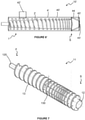
- extruder screw 1 according to a first embodiment of the invention, where the extruder screw 1 comprises a shaft 2 about which a helical flight 3 extends.
- the shaft 2 is formed of a thermally conductive material for conducting heat, in use, as will be described in greater detail below.
- the shaft 2 has first end F and a second end S.
- the extruder screw 1 has three sections, first, second and third sections.
- the first end F is upstream and the second end S is downstream (in use).
- the first section is at and/or adjacent the first end F and comprises a feed section FS
- the third section is at and/or adjacent the second end S and comprises a metering section MS
- the second section is between the first and third sections and comprises a transition section TS.
- the shaft 2 is generally cylindrical and has a first diameter D 1 at the first end F and a second diameter D 2 at the second end S.
- the second diameter D 2 is greater than the first diameter D 1 .
- the diameter of the shaft 2 remains substantially constant in the metering section MS.
- the diameter of the shaft 2 gradually increases from the first diameter D 1 to the second diameter D 2 in the feed section FS and in the transition section TS.
- the shaft 2 has an at least partially hollow core within which is a heater, for example a high-speed self-recuperative burner (not shown) is installed.
- a heater for example a high-speed self-recuperative burner (not shown) is installed.
- the outer radius R of the flight 3 is constant along the length of the shaft 2. Accordingly, because the diameter of the shaft 2 alters along its length then so too does the depth d of the flight 3.
- the depth d of the flight 3 refers to the distance by which the flight 3 extends from the outer surface of the shaft 2 to the outer radius R of the flight 3.
- the depth d of the flight 3 decreases from the first end F toward the second end S of the shaft 2.
- the flight 3 may have a helix angle ⁇ which changes along its length.
- the flight 3 has a pitch P, that being the longitudinal distance between successive helical turns of the flight 3.
- the helix angle ⁇ varies in relation to the pitch P, i.e. the helix angle ⁇ of the flight 3 is relatively larger at sections wherein the pitch P is relatively greater, and vice versa.
- the pitch P of the flight 3 alters along the length of the shaft 2.
- the pitch P adjacent the first end F of the shaft 2 is greater than is the pitch adjacent the second end S of the shaft 2.
- the pitch P of the flight 3 remains substantially constant along the length of the shaft 2.
- the pitch P in the metering section MS gradually reduces in the downstream direction, i.e. from the transition section TS toward the second end S of the shaft 2.
- the reduction in pitch P of the flight 3 in the metering section MS provides an increased surface area for the biomass to contact the flight 3, which in turn increases the heat transfer in the metering section MS.
- a securement member 20 extends from the first end F of the shaft 2.
- the securement member 20 is adapted to be secured, in use, to a prime mover (not shown) suitable for providing rotational motive force or to a gear (not shown) or other intermediary element suitable for transferring rotational force from a prime mover.
- the second end S of the shaft 2 comprises a conical extension 5 co-aligned with the longitudinal axis of the shaft 2.
- each aperture 30 has a first area on a first, upstream face 31 of a turn of the flight 3 and second area on a second, downstream face 32 of the turn of the flight 3.
- the second area is greater than is the first area.
- Each aperture 30 tapers from the first area to the second area, for example in the downstream direction.
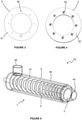
- a pyrolysis reactor 10 comprising a barrel 4 within which is the extruder screw 1 shown in Figures 1 and 2 .
- the barrel 4 has a generally cylindrical shape and is shaped and sized to closely surround the extruder screw 1.
- the barrel 4 has a barrel wall 40 which is formed from a thermally conductive material. The barrel 4 is heated, in use, as will be described below in greater detail.
- a pyrolysis chamber 41 is defined within the barrel 4.
- the extruder screw 1 is located within the pyrolysis chamber 41.
- the barrel wall 40 extends along the length of the shaft 2 (when the extruder screw 1 is within the barrel 4).
- a clearance distance C d is defined between the outer edge of the flight 3 and the inner surface of the barrel wall 40. The clearance distance C d is substantially constant along the length of the shaft 2.
- the barrel 4 has an inlet 42 adjacent the feed section FS of the extruder screw 1 and an outlet 43 adjacent the second end S of the shaft 2.
- the outlet 43 is co-axial with the longitudinal axis of the shaft 2.
- the outlet 43 is reduced in area relative to the diameter of the barrel 4, thereby forming a nozzle downstream of the second end S of the shaft 2.
- the barrel 4' further comprises an outer wall 44 and a region 45.
- the outer wall 44 circumferentially extends around, and covers (at least in part) the barrel wall 40' to longitudinally extend towards or beyond the outlet 43' of the barrel 4'.
- the outer wall 44 begins at the downstream, second end S' of the shaft 2' and terminates at the edge of the barrel wall 40' at the outlet 43'.
- the outer wall 44 is co-axial with the barrel wall 40' and the shaft 2', and is cylindrical, so has a substantially constant diameter.
- the outlet 43' is a nozzle and so the outlet 43' has a relatively reduced diameter in comparison to the outer wall 44.
- the region 45 is represented schematically as a void.
- the outer wall 44 and the region 45 may be formed from any suitable material, e.g. a thermally conductive material such as metal, and may comprise a solid wall that is continuous with the barrel wall 40', i.e. in embodiments of the pyrolysis reactor 10', the region 45 comprises solid metal, and therefore there is no void between the outer wall 44 and the barrel wall 40' surrounding the outlet 43'.
- the thickness of the outer wall 44 and the barrel wall 40', particularly surrounding the outlet 43' provides additional mechanical strength to ensure that the barrel wall 40' does not buckle under the high pressures experienced in the metering section MS of the extruder screw 1', wherein the biomass is subjected to high operating temperatures during the final compressive stages of pyrolysis.
- the pressure exerted by the compressed biomass on the barrel wall 40, 40' is proportional to the effectiveness of the pyrolysis action.
- higher ablative pressure in the metering section, wherein the biomass is highly compressed will reduce the external heating requirement in that section or zone.
- the extruder screw 1 is attached (either directly or indirectly) to a motor or other prime mover (not shown) prior to use of the pyrolysis reactor 10, 10'.
- the high-speed self-recuperative burner within the shaft 2, 2' is activated to thereby heat the shaft 2, 2'.
- the barrel wall 40, 40' of the barrel 4, 4' is also heated by an external heat source (not shown).
- the pyrolysis reactor 10, 10' is operated at a temperature of between 200°C and 900°C, dependent on the substance to be pyrolyzed, the products of pyrolysis required and the desired speed and/or efficiency of pyrolysis.
- biomass waste residue is fed through the inlet 42, 42' into the pyrolysis chamber 41, 41' within the barrel 4, 4'.
- the motor or other prime mover is activated to cause the extruder screw 1 to rotate relative to the barrel 4, 4'.
- 3' causes the introduced biomass waste residue to be conveyed along the reactor 10, 10' from the feed section FS toward the outlet 43, 43'.
- Thermal energy is transferred from the heated barrel wall 40, 40' and from the heated shaft 2, 2' to the biomass waste residue within the pyrolysis chamber 41, 41'.
- This transfer of heat causes pyrolysis of the biomass waste residue and converts it into vapour and biochar.
- the helix angle ⁇ of the flight 3, 3' causes, due to rotation of the extruder screw 1 conveyance of the biomass waste residue and its converted products from the inlet 42, 42' to the outlet 43, 43'.
- a mix of phases of products of pyrolysis of the biomass waste residue is ejected from the outlet 43, 43' of the reactor 10, 10'. This mix of phases of products is then separated in a further downstream process (not shown).
- pyrolysis will gradually occur, such that a mass nearer to the outlet will have a relatively greater concentration of pyrolysis products than does a mass nearer to the inlet, i.e. the rate of pyrolysis will increase as the mass is conveyed from the inlet towards the outlet.
- the rate of pyrolysis is dependent upon the residence time of the mass within the reactor.
- the mass of the particles of pyrolysis relatively decrease in size along the length of the reactor 10, in the downstream direction.
- the products of pyrolysis of biomass waste residue comprise both vapours and solids. Accordingly, in use, there will be a relatively higher concentration of vapours toward the outlet than there are adjacent the inlet.
- Relatively smaller particles occupy less volume when compressed together than do relatively larger particles and, accordingly, reducing the working volume ensures a constant pressure of said particles of reduced size against the working surfaces of the pyrolysis reactor 10.
- the reduction in particle size affects the heat transfer coefficient of the biomass, which in turn affects the mechanism of pyrolysis.
- the relatively enhanced concentrations of low-molecular weight fuel gas products generated by the above-described apparatus and method do not require the use of relatively higher input temperatures. Accordingly, the barrel 4, 4' of the reactor 10, 10' and the extruder screw 1, 1' do not need to be formed from more expensive materials or be constructed in a more expensive manner. The above-described apparatus and method thereby result in relative cost savings.
- the temperature distribution profile between the inner surface of the barrel wall 40 and the outer surface of the shaft 2, 2' may be relatively improved. Heating of the shaft 2, 2' allows heat to be transferred to the biomass waste residue from the shaft 2, 2' and the flight 3, 3' in addition to the barrel wall 40, 40'.
- the active surface area for pyrolysis within the reactor 10, 10' is thereby relatively increased and the efficiency of pyrolysis is accordingly relatively enhanced.
- the apertures 30 through the flight 3, 3' advantageously allow passage of vapour from the first, upstream face 31 of a turn of a flight 3 to the second, downstream face 32 of the turn of the flight 3.
- This increased mobility of the vapour within the reactor 10, 10' allows for enhanced mixing of the phases of products of pyrolysis within the reactor 10, 10'.
- provision of the apertures 30 mitigates against the build-up of excessive vapour pressures between adjacent turns of the flight 3, 3'.
- the tapered shape of the apertures 30 (increasing in size in the downstream direction) accelerates vapour passing therethrough due to expansion of the vapour through each aperture 30, i.e.
- the phases of the products are able to be relatively more completely mixed within the reactor 10, 10'. Due to this relatively enhanced mixing of the phases of the products further thermal cracking of the products is relatively increased. Accordingly, the characteristics of the mixture leaving the outlet 43, 43' of the reactor 10, 10' can be more readily controlled.
- the apparatus according to the invention is readily scalable and can therefore be used for pyrolysis of biomass waste residues in laboratory bench tests at feed rates of 1 kg/hr up to industrial scale processing at feed rates of, for example, 10,000 kg/hr.
- the apparatus according to the invention is suitable for processing biomass waste residue with a moisture content of up to 30% and/or having particle sizes having a maximum diameter ranging from 2 mm to 100 mm.
- extruder screw 11 according to a further embodiment of the invention, wherein like features to those of the extruder screw 1 shown in Figures 1 and 2 are depicted by like references preceded by a '1', and will not be described further herein.
- the extruder screw 11 shown in Figures 7 and 8 differs from that shown in Figures 1 and 2 in that the extruder screw 11 has a fourth section, an outlet section OS, downstream of the metering section MS.
- the shaft 12 is not heated, in use, and accordingly need not be formed from a thermally conductive material (though it may be, in any event).
- the shaft 12 does not, therefore, have a partially hollow core within which a high-speed self-recuperative burner is installed.
- the diameter D 3 of the shaft 2 in the outlet section OS is the same as the diameter D 1 of the shaft 2 at the first end F of the shaft 2. Accordingly, the diameter D 3 of the shaft 2 in the outlet section OS is less than the diameter D 2 of the shaft 2 in the metering section MS.
- the outer radius of the flight is the same in the outlet section OS as it is in the other sections of the extruder screw 11. Accordingly, the depth d 1 of the flight is relatively greater in the outlet section OS than it is in the metering section MS.
- the pitch P 1 of the flight 3 is greater in the outlet section OS than it is in the metering section MS. In particular, the pitch P of the flight 3 is greater in the outlet section OS than is the pitch P of the flight toward the downstream end of the metering section MS.
- the pyrolysis reactor 110 shown in Figures 9 and 10 comprises an barrel 14 within which is the extruder screw 11 shown in Figures 7 and 8 .
- the barrel 14 of the rector 110 differs from the barrel 4 shown in Figures 5 and 6 in that there are two outlets (first outlet 143a and second outlet 143b) instead of a single outlet 43, and the outlets 143a, 143b are not co-axial with the extruder screw 11. Instead, the first and second outlets 143a, 143b extend in directions substantially perpendicular to the longitudinal axis of the extruder screw 11.
- the first and second outlets 143a, 143b are located adjacent to the outlet section OS of the extruder screw 11.
- the pyrolysis reactor 110 is arranged so that the first outlet 143a is uppermost and the second outlet 143b is lowermost (e.g. the first outlet 143a is relatively above the second outlet 143b).
- pyrolysis of biomass waste residue within pyrolysis reactor 110 occurs as described above in respect of the pyrolysis reactor 10, with two differences: firstly the shaft 12 is not heated, and secondly the products of pyrolysis are separated before they exit the pyrolysis reactor 110.
- a pyrolysis reactor 111 which is not an embodiment of the invention, wherein like references to those previously described are designated with a double prime".
- the pyrolysis reactor 111 has similar features to those described in Figures 5 , 6, and 5' , and 6' .
- the shaft 2" of the screw 1" has a constant diameter along its length, although it should be noted that the diameter of the shaft 2" and/or the depth of the flight 3" may vary along the length of the shaft 2" in alternative embodiments.
- FIG. 11A there is shown a side view of the pyrolysis reactor 111 comprising a barrel 4" and a screw 1".
- the barrel 4" comprises an outer wall 44" and is shaped and sized to closely surround the screw 1".
- the barrel 4" defines a pyrolysis chamber 41" in which is located the screw 1".
- the screw 1" comprises a shaft 2" (preferably a centreless shaft) with a first end F" and a second end S".
- the shaft 2" comprises a flight 3".
- the flight 3" and/or the reactor 111 comprises a feed section FS", a transition section TS" and a metering section MS".
- the pitch of the flight 3" is the same in the feed section FS" and transition section TS".
- the shaft 2" is mounted for rotation within the barrel 4" on mounts 50" which are configured to allow rotation of the shaft 2" and are provided with seals 51" disposed about a mounting plate 52" for retaining heating tubes H.
- the barrel 4" comprises an inlet 42" for receiving material to be pyrolosed (for example biomass) adjacent the first end F" and an outlet 43" adjacent the second end S" of the shaft 2".
- the inlet 42" and the outlet 43" are both positioned perpendicular to the longitudinal axis of the shaft 2".
- the pyrolysis reactor 111 further comprises a motor M" for rotation of the shaft 2" within the barrel 4".
- FIG. 11B and 11C there is shown a front elevation 111A and the rear elevation 111B of the shaft 2" of the screw 1".
- a heater H within the shaft 2".
- the heater 2" is provided as hollow heater tubes located 54" within a single or individual recesses of the shaft 2".
- the heater H is mounted for rotation at a first mount M1 and a second mount M2.
- the inlet 42" and outlet 43" are each located inboard of the first mount M1 and the second mount M2.
- biomass waste residue is fed through the inlet 42" into the pyrolysis chamber 41" within the barrel 4".
- the motor M" is activated to cause the screw 1" and the heater H to rotate relative to the barrel 4′′′.
- the screw 1" rotates the helix angle of the flight 3" causes the introduced biomass waste residue to be conveyed along the pyrolysis reactor 111 from the feed section FS" toward the outlet 43".
- Thermal energy is transferred from the heater H to the biomass waste residue within the pyrolysis chamber 41".
- This transfer of heat causes pyrolysis of the biomass waste residue and converts it into vapour and biochar.
- the helix angle of the flight 3" causes, due to rotation of the screw 1" conveyance of the biomass waste residue and its converted products from the inlet 42" to the outlet 43".
- a mix of phases of products of pyrolysis of the biomass waste residue is ejected from the outlet 43" of the reactor 111. This mix of phases of products is then separated in a further downstream process (not shown).
- provision of an internal heater H within the shaft 2" of the screw 1" such that it is rotatable within the barrel 4" enables greater heat transfer to the biomass waste, and hence the pyrolysis reaction is more efficient.
- the barrel may also be externally heated to further improve heat transfer to the biomass or other material.
- the pyrolysis process may be used to generate syngas.
- Some of the syngas may be used to generate heat which can be supplied to the heat inlet 55" and along the heater tubes 54" of the heater H to the outlet 56".
- the heat inlet 5" is in communication with a manifold 57" which is separated from the pyrolysis reaction zone by the seals 51" and plate 52".
- heat heat (heated gas) flows from the heat inlet 55" to the heat outlet 56" via the hollow tubes 54" to heat biomass or other material within the reactor.
- heaters H for example resistively heated tubes, inductively heated tubes, radiant heat elements and so on but the use of heated fluid has proven to be the most efficacious.
- the extruder screw 1, 11 may comprise more than one flight 3, 3', 13.
- the heater within the shaft 2, 2', 12 of the screw, e.g. extruder screw 1, 11, and/or the external heat source of the barrel 4, 4', 14 may comprise several heaters that may be separately controllable to heat a respective region of the shaft and/or barrel to a specific temperature or temperature range.
- the feed section FS, the transition section TS, the metering section MS, and/or the outlet section OS may each comprise a different heater, which each heat to a different temperature, e.g. each heater provides a progressively higher temperature to each section or zone, going from the feed section FS, through the transition section TS, the metering section MS, and finally to the outlet section OS.
- the difference in temperature experienced within each section may comprise a step change in temperature.
- the feed section FS may be provided with a heater in the shaft 2, 2', 12 and/or an external heat source to the barrel 4, 4', 14, which heats to a temperature of, for example, approximately 200 °C to begin the process of pyrolysis.
- the transition section TS may be provided with a separate heater that heats to a temperature of, for example, 500 °C.
- the metering section MS may be provided with a further heater that heats the biomass to a temperature of, for example, between 600 to 750 °C.
- the temperature change experienced as the biomass progresses along the extruder screw 1, 11 may be gradual, e.g. the temperature may gradually increase from the feed section FS to the metering section MS and/or the outlet section OS.
- the shape and structure of the outlet 43, 43' may influence the temperature at which the biomass may be heated at the final stages of pyrolysis. For example, if the outlet 43, 43' comprises a conical, tapered end, then the temperature at which the biomass may be heated in the metering section MS and/or outlet section OS is higher than if the outlet is a cylinder with a continuous diameter, which is coaxial with the extruder screw 1, 1' 11.
Landscapes
- Chemical & Material Sciences (AREA)
- Engineering & Computer Science (AREA)
- Oil, Petroleum & Natural Gas (AREA)
- Materials Engineering (AREA)
- Organic Chemistry (AREA)
- Combustion & Propulsion (AREA)
- Processing Of Solid Wastes (AREA)
Claims (15)
- Pyrolysereaktor (10; 10'; 110) mit einem Einlauf (42; 42'; 142) für Material und einem Auslauf (43; 43'; 143a, 143b) für Produkte, wobei der Reaktor (10; 10'; 110) eine Schnecke (1; 1'; 11) zum Fördern von Biomasseabfällen von dem Einlauf (42; 42'; 142) zu dem Auslauf (43; 43'; 143a, 143b) umfasst, wobei die Schnecke (1; 1'; 11) eine Welle (2; 2'; 12) mit einem ersten Ende (F) und einem zweiten Ende (S) angrenzend an den Auslauf (43; 43'; 143a, 143b) und einem wendelförmigen Gang (3; 3'; 13), der um die Welle (2; 2'; 12) herum angeordnet ist und sich zwischen dem ersten (F) und dem zweiten Ende (S) erstreckt, umfasst, wobei die Schnecke (1; 1'; 11) einen Zuführabschnitt (feed section, FS) am oder angrenzend an den Einlauf (42; 42'; 142), einen Dosierabschnitt (metering section, MS) am oder angrenzend an den Auslauf (43; 43'; 143a, 143b) und einen Übergangsabschnitt (transition section, TS) zwischen dem Zuführabschnitt (FS) und dem Dosierabschnitt (MS) umfasst, wobei die Steigung (pitch, P) des Gangs (3; 3'; 13) in dem Dosierabschnitt (MS) kleiner ist als in dem Zuführabschnitt (FS) und/oder in dem Übergangsabschnitt (TS), der Durchmesser (D1, D2) der Welle (2; 2'; 12) entlang ihrer Länge in Richtung des Auslaufs (43; 43'; 143a, 143b) zunimmt, die Tiefe (depth, d) des Gangs (3; 3'; 13) in dem Dosierabschnitt (MS) kleiner ist als in dem Zuführabschnitt (FS) und/oder in dem Übergangsabschnitt (TS), wobei die Schnecke (1; 1'; 11) eine Heizung aufweist, die sich von dem ersten Ende (F) zu dem zweiten Ende (S) erstreckt.
- Pyrolysereaktor nach einem vorhergehenden Anspruch, wobei der Außendurchmesser des Gangs (3; 3'; 13) entlang der Länge der Welle (2; 2'; 12) im Wesentlichen konstant ist, z. B. der Außendurchmesser jeder Windung des Gangs (3; 3'; 13) entlang des Gangs (3; 3'; 13) im Wesentlichen gleich ist.
- Pyrolysereaktor nach einem vorhergehenden Anspruch, wobei der Steigungswinkel, z. B. Steigungswinkel β, des Gangs (3; 3'; 13) entsprechend einer Zunahme oder Abnahme der Steigung (P) des Gangs (3; 3'; 13) entlang der Länge der Welle (2; 2'; 12) variiert.
- Pyrolysereaktor nach einem vorhergehenden Anspruch, wobei die Welle (2; 2'; 12) eine oder mehrere Vertiefungen, z. B. eine mittige Vertiefung oder eine Vielzahl von Vertiefungen, die außermittig angeordnet ist und sich entlang mindestens eines Teils der Länge der Welle (2; 2'; 12) erstreckt, umfasst, wobei sich beispielsweise die eine oder mehreren Vertiefungen entlang mindestens eines Teils der Länge der Welle (2; 2'; 12), z. B. der gesamten Länge der Welle (2; 2'; 12), erstrecken und/oder wobei die eine oder mehreren Vertiefungen dazu konfiguriert sind, die Heizung aufzunehmen und/oder zu halten.
- Pyrolysereaktor nach einem vorhergehenden Anspruch, wobei die Tiefe (d) des Gangs (3; 3'; 13) bei mindestens einer der Windungen des Gangs (3; 3'; 13) in dem Dosierabschnitt (MS) kleiner ist als in dem Zuführabschnitt (FS) und/oder in dem Übergangsabschnitt (TS).
- Pyrolysereaktor nach einem vorhergehenden Anspruch, wobei die Schnecke (1; 1'; 11) und/oder die Welle (2; 2'; 12) ferner den Auslaufabschnitt umfasst/-en, der sich zwischen dem Dosierabschnitt (MS) und dem zweiten Ende befindet, und wobei beispielsweise die Welle (2; 2'; 12) des Auslaufabschnitts einen verringerten Durchmesser aufweist, der z. B. in Bezug auf den Durchmesser der Welle (2; 2'; 12) in dem Dosierabschnitt (MS) verringert ist, wobei beispielsweise die Welle (2; 2'; 12) des Auslaufabschnitts ferner ein konisches oder sich verjüngendes Ende, z. B. ein sich verjüngendes Ende koaxial zu einer Längsachse der Welle (2; 2'; 12), umfasst.
- Pyrolysereaktor nach Anspruch 6, wobei die Steigung und/oder die Tiefe des Gangs (3; 3'; 13) an dem Auslaufabschnitt der Schnecke (1; 1'; 11) größer ist/sind als in dem Dosierabschnitt (MS).
- Pyrolysereaktor nach einem vorhergehenden Anspruch, ferner umfassend eine oder mehrere Öffnungen, die sich durch den Gang (3; 3'; 13) erstrecken, wobei beispielsweise eine oder mehrere Windungen des Gangs (3; 3'; 13) in dem Dosierabschnitt (MS) die eine oder mehreren Öffnungen umfassen, wobei beispielsweise der Gang (3; 3'; 13) in dem Zuführabschnitt (FS) und/oder dem Übergangsabschnitt (TS) frei von Öffnungen ist.
- Pyrolysereaktor nach einem vorhergehenden Anspruch, ferner umfassend ein Eingriffselement, das derart konfiguriert ist, dass es einen Eingriff zwischen der Welle (2; 2'; 12) und einem Aktor zum Drehen der Welle (2; 2'; 12) ermöglicht.
- Pyrolysereaktor nach einem vorhergehenden Anspruch, wobei die Heizung und die Schnecke (1; 1'; 11) derart angeordnet sind, dass sie sich drehen.
- Pyrolysereaktor nach einem vorhergehenden Anspruch, ferner umfassend ein Gehäuse oder einen Zylinder, wobei das Gehäuse oder der Zylinder beispielsweise derart dimensioniert und/oder geformt ist, dass es bzw. er die Schnecke (1; 1'; 11) eng umgibt, beispielsweise wenn es bzw. er darin angeordnet ist.
- Pyrolysereaktor nach einem vorhergehenden Anspruch, wobei der Auslauf (143a, 143b) einen ersten und einen zweiten Auslauf (143a, 143b) umfasst und/oder der erste Auslauf (143a) bei Gebrauch derart angeordnet oder anordenbar ist, dass Dampf- und/ oder Gasprodukte der Pyrolyse aus dem Gehäuse oder Zylinder dadurch hindurch austreten können, und/oder der zweite Auslauf (143b) bei Gebrauch derart angeordnet oder anordenbar ist, dass Nicht-Dampf- und/oder nicht gasförmige Produkte aus dem Gehäuse oder Zylinder dadurch hindurch austreten können.
- Pyrolysereaktor nach einem vorhergehenden Anspruch, wobei die Heizung zur Drehung an einer ersten Halterung und einer zweiten Halterung angebracht ist und wobei sich der Einlauf (42; 42'; 142) und der Auslauf jeweils innerhalb der ersten Halterung und der zweiten Halterung befinden.
- Verfahren zum Pyrolysieren von Biomasseabfallresten in einem Pyrolysereaktor (10; 10'; 110) nach einem vorhergehenden Anspruch, wobei das Verfahren die folgenden Schritte umfasst:a) Erhitzen von Biomasseabfallresten zwischen dem ersten (F) und dem zweiten (S) Ende der Schnecke (1; 1'; 11), um die Biomasseabfallreste durch Erhitzen der Schnecke (1; 1'; 11) teilweise zu pyrolysieren; undb) Erhöhen des Drucks der teilweise pyrolysierten Biomasseabfallreste, um dadurch die teilweise pyrolysierten Biomasseabfallreste weiter zu pyrolysieren.
- Verfahren zum Pyrolysieren von Biomasse nach Anspruch 14, ferner umfassend einen oder mehrere der folgenden Schritte: einen Schritt c) des Bewegens oder Förderns der Biomasseabfallreste und/oder der teilweise pyrolysierten Biomasseabfallreste, einen Schritt d) des Mischens von Phasen von Produkten der teilweise pyrolysierten Biomasseabfallreste, einen Schritt e) des Einführens der Biomasseabfallreste in einen Pyrolysereaktor (10; 10'; 110), und/oder wobei der Schritt e) vor den Schritten a) und b) stattfindet, oder einen Schritt f) des Trennens von Phasen von Produkten der weiter pyrolysierten Biomasseabfallreste, beispielsweise innerhalb des Reaktors (10; 10'; 110).
Applications Claiming Priority (2)
| Application Number | Priority Date | Filing Date | Title |
|---|---|---|---|
| GBGB1719688.2A GB201719688D0 (en) | 2017-11-27 | 2017-11-27 | Pyrolysis |
| PCT/GB2018/053427 WO2019102232A1 (en) | 2017-11-27 | 2018-11-27 | Pyrolysis reactor and method of pyrolyzing biomass waste residue |
Publications (2)
| Publication Number | Publication Date |
|---|---|
| EP3717593A1 EP3717593A1 (de) | 2020-10-07 |
| EP3717593B1 true EP3717593B1 (de) | 2022-02-23 |
Family
ID=60950584
Family Applications (1)
| Application Number | Title | Priority Date | Filing Date |
|---|---|---|---|
| EP18815284.7A Active EP3717593B1 (de) | 2017-11-27 | 2018-11-27 | Pyrolysereaktor und verfahren zur pyrolyse von biomasseabfallresten |
Country Status (5)
| Country | Link |
|---|---|
| US (1) | US11299677B2 (de) |
| EP (1) | EP3717593B1 (de) |
| GB (1) | GB201719688D0 (de) |
| WO (1) | WO2019102232A1 (de) |
| ZA (1) | ZA202003404B (de) |
Families Citing this family (7)
| Publication number | Priority date | Publication date | Assignee | Title |
|---|---|---|---|---|
| FI129499B (en) * | 2018-02-26 | 2022-03-31 | Teknologian Tutkimuskeskus Vtt Oy | Procedure for performing thermolysis and thermolysis equipment |
| WO2024226972A2 (en) * | 2023-04-28 | 2024-10-31 | Ccl Label, Inc. | Fast pyrolysis system |
| CN116765094B (zh) * | 2023-05-25 | 2024-04-26 | 龙基能源集团有限公司 | 有机固体废弃物资源利用方法和装置 |
| PT118934B (pt) * | 2023-09-22 | 2024-12-04 | Iterum Novus Ltd | Sistema compreendendo uma zona de craqueamento térmico de uma corrente de vapor ligada a uma zona de pirólise |
| CN117564065A (zh) * | 2023-11-09 | 2024-02-20 | 重庆远达烟气治理特许经营有限公司科技分公司 | 废旧电池处理装置与利用光热源的废旧电池处理系统 |
| US12570903B2 (en) | 2023-12-10 | 2026-03-10 | Seyed Farshid Bahari | Pyrolysis reactor, pyrolysis system and methods of use thereof |
| KR102922474B1 (ko) * | 2025-02-05 | 2026-02-03 | 박희용 | 스크류형 열분해 장치 |
Family Cites Families (29)
| Publication number | Priority date | Publication date | Assignee | Title |
|---|---|---|---|---|
| US3787292A (en) | 1971-08-13 | 1974-01-22 | E Keappler | Apparatus for pyrolysis of wastes |
| US4250158A (en) * | 1978-02-15 | 1981-02-10 | Intenco, Inc. | Process for recovering carbon black and hydrocarbons from used tires |
| US4218222A (en) | 1978-09-07 | 1980-08-19 | Texaco Inc. | Method of charging solids into coal gasification reactor |
| US4686008A (en) * | 1985-10-08 | 1987-08-11 | Gibson Harry T | Pyrolytic decomposition apparatus |
| US5017269A (en) * | 1988-12-28 | 1991-05-21 | Apv Chemical Machinery Inc. | Method of continuously carbonizing primarily organic waste material |
| US5389691A (en) * | 1993-09-07 | 1995-02-14 | Univ. Of Wyoming | Process for co-recycling tires and oils |
| JPH09291290A (ja) | 1996-04-26 | 1997-11-11 | Toshiba Corp | プラスチック処理装置及びプラスチック油化処理装置 |
| US6221329B1 (en) * | 1999-03-09 | 2001-04-24 | Svedala Industries, Inc. | Pyrolysis process for reclaiming desirable materials from vehicle tires |
| CA2303795A1 (en) | 2000-03-27 | 2001-09-27 | Zenon Todorski | Process for continuous pyrolysis of wood chips and other cellulosic materials with the objective of maximizing the yield of methanol, other liquid organics, and activated carbon |
| JP3868757B2 (ja) * | 2001-04-25 | 2007-01-17 | 株式会社神戸製鋼所 | ゴム系組成物の混練装置および混練方法 |
| EP1405895A1 (de) * | 2002-10-04 | 2004-04-07 | Danieli Corus Technical Services BV | Vorrichtung und Verfahren zur pyrolytischen Behandlung eines Materials, und Verwendung davon |
| US7144558B2 (en) * | 2004-07-01 | 2006-12-05 | Biogas Technologies, Inc. | Wood gasification apparatus |
| CA2539012C (en) * | 2006-03-10 | 2013-07-09 | John Flottvik | Closed retort charcoal reactor system |
| US20090007484A1 (en) | 2007-02-23 | 2009-01-08 | Smith David G | Apparatus and process for converting biomass feed materials into reusable carbonaceous and hydrocarbon products |
| DE102008012156A1 (de) | 2008-03-01 | 2009-09-03 | Karl-Heinz Tetzlaff | Schneckenförderer zur Einspeisung von Biomasse in einen Druckbehälter |
| IT1396562B1 (it) | 2009-03-24 | 2012-12-14 | Rebai | Metodo e reattore chimico per la produzione di idrocarburi gassosi derivanti da materie plastiche. |
| US8328993B2 (en) * | 2009-05-18 | 2012-12-11 | Greenlight Energy Solutions, Llc | Pyrolysis reactor for processing municipal wastes |
| US7947155B1 (en) * | 2009-11-17 | 2011-05-24 | Green Liquid and Gas Technologies | Process and device for the pyrolysis of feedstock |
| EP2545146A4 (de) * | 2010-03-08 | 2014-05-07 | Arthur M Shulenberger | Vorrichtung und verfahren zur umwandlung von biomasse in biokraftstoff |
| CN201857370U (zh) | 2010-08-20 | 2011-06-08 | 华北电力大学 | 外置式生物质螺旋进料器 |
| WO2012100247A2 (en) * | 2011-01-23 | 2012-07-26 | Tucker Jerry | Self-sustaining pyrolysis system for energy production |
| WO2012136344A1 (de) | 2011-04-06 | 2012-10-11 | Olabil Vermögensverwaltungsgesellschaft Mbh | Förderelement zum fördern eines guts und verfahren zur durchführung eines pyrolytischen prozesses unter verwendung eines solchen förderelements |
| US9005402B2 (en) * | 2011-05-14 | 2015-04-14 | Interra Energy, Inc. | Reciprocating reactor and methods for thermal decomposition of carbonaceous feedstock |
| RU2014134429A (ru) * | 2012-02-09 | 2016-04-10 | Вадэксэкс Энерджи Ллс | Разграниченный на зоны аппарат для пиролиза для переработки полимерных отходов |
| KR101490414B1 (ko) | 2012-12-07 | 2015-02-04 | 주식회사 재원에너지 | 가변 피치 방식의 열 분해관 및 이를 이용한 오일 추출 장치 |
| DE202013101154U1 (de) | 2013-03-18 | 2013-04-22 | Matthias Überdiek | Pyrolyseaggregat für feuchte Biomasse |
| PL227338B1 (pl) | 2013-07-12 | 2017-11-30 | Fluid Spółka Akcyjna | Sposób przetwarzania biomas w paliwo odnawialne i urzadzenie do przetwarzania biomas w paliwo odnawialne |
| GB2527830A (en) * | 2014-07-03 | 2016-01-06 | Dps Bristol Holdings Ltd | Waste processing apparatus |
| FI129499B (en) * | 2018-02-26 | 2022-03-31 | Teknologian Tutkimuskeskus Vtt Oy | Procedure for performing thermolysis and thermolysis equipment |
-
2017
- 2017-11-27 GB GBGB1719688.2A patent/GB201719688D0/en not_active Ceased
-
2018
- 2018-11-27 US US16/975,998 patent/US11299677B2/en active Active
- 2018-11-27 EP EP18815284.7A patent/EP3717593B1/de active Active
- 2018-11-27 WO PCT/GB2018/053427 patent/WO2019102232A1/en not_active Ceased
-
2020
- 2020-06-08 ZA ZA2020/03404A patent/ZA202003404B/en unknown
Also Published As
| Publication number | Publication date |
|---|---|
| US11299677B2 (en) | 2022-04-12 |
| WO2019102232A1 (en) | 2019-05-31 |
| EP3717593A1 (de) | 2020-10-07 |
| GB201719688D0 (en) | 2018-01-10 |
| ZA202003404B (en) | 2022-12-21 |
| US20210040392A1 (en) | 2021-02-11 |
Similar Documents
| Publication | Publication Date | Title |
|---|---|---|
| EP3717593B1 (de) | Pyrolysereaktor und verfahren zur pyrolyse von biomasseabfallresten | |
| US20250304859A1 (en) | Method for pyrolysing plastic material and a system therefor | |
| RU2326926C2 (ru) | Устройство и способ для переработки материала при пиролитических условиях и их использование | |
| EP2118241B1 (de) | Pyrolysatorofenvorrichtung | |
| US7625532B2 (en) | Ablative thermolysis reactor | |
| US20050039652A1 (en) | Multi retort pyrolytic waste treatment system | |
| CN116018203B (zh) | 塑料转换进料系统 | |
| WO2020051702A1 (en) | Pyrolysis system and method of use | |
| WO2014167141A1 (en) | Screw conveyor reactor and use for pyrolysis or torrefaction of biomass | |
| GB2062669A (en) | Hydrogenation of coal to produce liquid fuels | |
| CN101616970A (zh) | 用于使长链有机物质的分子结构裂解的设备 | |
| US8128717B2 (en) | Mechanically driven centrifugal pyrolyzer | |
| FI61752C (fi) | Pyrolysreaktor foer konvertering av avfallsmaterial | |
| US7902326B2 (en) | Process for breaking the carbon chains of organic molecules of solid materials and related apparatus | |
| RU2780833C1 (ru) | Способ получения продуктов термической деструкции резиновой крошки, полученной из использованных автомобильных шин | |
| RU2776712C1 (ru) | Способ получения продуктов термической деструкции илового осадка городских сточных вод | |
| JP2021105187A (ja) | チャー分離器及び方法 | |
| US20120018677A1 (en) | Method and device for processing plastics waste, especially polyolefines | |
| EP2451895A1 (de) | Vorrichtung zur wärmebehandlung eines organischen materials und verfahren zur verwendung dieser vorrichtung | |
| WO2025104111A1 (en) | Screw conveyor for pyrolysis system | |
| FI20185175A1 (en) | Method for carrying out thermolysis and thermolysis apparatus | |
| CA3256225A1 (en) | A method for pyrolysing plastic material and a system therefor |
Legal Events
| Date | Code | Title | Description |
|---|---|---|---|
| STAA | Information on the status of an ep patent application or granted ep patent |
Free format text: STATUS: UNKNOWN |
|
| STAA | Information on the status of an ep patent application or granted ep patent |
Free format text: STATUS: THE INTERNATIONAL PUBLICATION HAS BEEN MADE |
|
| PUAI | Public reference made under article 153(3) epc to a published international application that has entered the european phase |
Free format text: ORIGINAL CODE: 0009012 |
|
| STAA | Information on the status of an ep patent application or granted ep patent |
Free format text: STATUS: REQUEST FOR EXAMINATION WAS MADE |
|
| 17P | Request for examination filed |
Effective date: 20200615 |
|
| AK | Designated contracting states |
Kind code of ref document: A1 Designated state(s): AL AT BE BG CH CY CZ DE DK EE ES FI FR GB GR HR HU IE IS IT LI LT LU LV MC MK MT NL NO PL PT RO RS SE SI SK SM TR |
|
| AX | Request for extension of the european patent |
Extension state: BA ME |
|
| DAV | Request for validation of the european patent (deleted) | ||
| DAX | Request for extension of the european patent (deleted) | ||
| GRAP | Despatch of communication of intention to grant a patent |
Free format text: ORIGINAL CODE: EPIDOSNIGR1 |
|
| STAA | Information on the status of an ep patent application or granted ep patent |
Free format text: STATUS: GRANT OF PATENT IS INTENDED |
|
| INTG | Intention to grant announced |
Effective date: 20210928 |
|
| GRAS | Grant fee paid |
Free format text: ORIGINAL CODE: EPIDOSNIGR3 |
|
| GRAA | (expected) grant |
Free format text: ORIGINAL CODE: 0009210 |
|
| STAA | Information on the status of an ep patent application or granted ep patent |
Free format text: STATUS: THE PATENT HAS BEEN GRANTED |
|
| AK | Designated contracting states |
Kind code of ref document: B1 Designated state(s): AL AT BE BG CH CY CZ DE DK EE ES FI FR GB GR HR HU IE IS IT LI LT LU LV MC MK MT NL NO PL PT RO RS SE SI SK SM TR |
|
| REG | Reference to a national code |
Ref country code: GB Ref legal event code: FG4D |
|
| REG | Reference to a national code |
Ref country code: CH Ref legal event code: EP |
|
| REG | Reference to a national code |
Ref country code: DE Ref legal event code: R096 Ref document number: 602018031338 Country of ref document: DE |
|
| REG | Reference to a national code |
Ref country code: AT Ref legal event code: REF Ref document number: 1470483 Country of ref document: AT Kind code of ref document: T Effective date: 20220315 |
|
| REG | Reference to a national code |
Ref country code: IE Ref legal event code: FG4D |
|
| REG | Reference to a national code |
Ref country code: FI Ref legal event code: FGE |
|
| REG | Reference to a national code |
Ref country code: NL Ref legal event code: FP |
|
| REG | Reference to a national code |
Ref country code: LT Ref legal event code: MG9D |
|
| REG | Reference to a national code |
Ref country code: AT Ref legal event code: MK05 Ref document number: 1470483 Country of ref document: AT Kind code of ref document: T Effective date: 20220223 |
|
| PG25 | Lapsed in a contracting state [announced via postgrant information from national office to epo] |
Ref country code: SE Free format text: LAPSE BECAUSE OF FAILURE TO SUBMIT A TRANSLATION OF THE DESCRIPTION OR TO PAY THE FEE WITHIN THE PRESCRIBED TIME-LIMIT Effective date: 20220223 Ref country code: RS Free format text: LAPSE BECAUSE OF FAILURE TO SUBMIT A TRANSLATION OF THE DESCRIPTION OR TO PAY THE FEE WITHIN THE PRESCRIBED TIME-LIMIT Effective date: 20220223 Ref country code: PT Free format text: LAPSE BECAUSE OF FAILURE TO SUBMIT A TRANSLATION OF THE DESCRIPTION OR TO PAY THE FEE WITHIN THE PRESCRIBED TIME-LIMIT Effective date: 20220623 Ref country code: NO Free format text: LAPSE BECAUSE OF FAILURE TO SUBMIT A TRANSLATION OF THE DESCRIPTION OR TO PAY THE FEE WITHIN THE PRESCRIBED TIME-LIMIT Effective date: 20220523 Ref country code: LT Free format text: LAPSE BECAUSE OF FAILURE TO SUBMIT A TRANSLATION OF THE DESCRIPTION OR TO PAY THE FEE WITHIN THE PRESCRIBED TIME-LIMIT Effective date: 20220223 Ref country code: HR Free format text: LAPSE BECAUSE OF FAILURE TO SUBMIT A TRANSLATION OF THE DESCRIPTION OR TO PAY THE FEE WITHIN THE PRESCRIBED TIME-LIMIT Effective date: 20220223 Ref country code: ES Free format text: LAPSE BECAUSE OF FAILURE TO SUBMIT A TRANSLATION OF THE DESCRIPTION OR TO PAY THE FEE WITHIN THE PRESCRIBED TIME-LIMIT Effective date: 20220223 Ref country code: BG Free format text: LAPSE BECAUSE OF FAILURE TO SUBMIT A TRANSLATION OF THE DESCRIPTION OR TO PAY THE FEE WITHIN THE PRESCRIBED TIME-LIMIT Effective date: 20220523 |
|
| PG25 | Lapsed in a contracting state [announced via postgrant information from national office to epo] |
Ref country code: PL Free format text: LAPSE BECAUSE OF FAILURE TO SUBMIT A TRANSLATION OF THE DESCRIPTION OR TO PAY THE FEE WITHIN THE PRESCRIBED TIME-LIMIT Effective date: 20220223 Ref country code: LV Free format text: LAPSE BECAUSE OF FAILURE TO SUBMIT A TRANSLATION OF THE DESCRIPTION OR TO PAY THE FEE WITHIN THE PRESCRIBED TIME-LIMIT Effective date: 20220223 Ref country code: GR Free format text: LAPSE BECAUSE OF FAILURE TO SUBMIT A TRANSLATION OF THE DESCRIPTION OR TO PAY THE FEE WITHIN THE PRESCRIBED TIME-LIMIT Effective date: 20220524 Ref country code: AT Free format text: LAPSE BECAUSE OF FAILURE TO SUBMIT A TRANSLATION OF THE DESCRIPTION OR TO PAY THE FEE WITHIN THE PRESCRIBED TIME-LIMIT Effective date: 20220223 |
|
| PG25 | Lapsed in a contracting state [announced via postgrant information from national office to epo] |
Ref country code: IS Free format text: LAPSE BECAUSE OF FAILURE TO SUBMIT A TRANSLATION OF THE DESCRIPTION OR TO PAY THE FEE WITHIN THE PRESCRIBED TIME-LIMIT Effective date: 20220623 |
|
| PG25 | Lapsed in a contracting state [announced via postgrant information from national office to epo] |
Ref country code: SM Free format text: LAPSE BECAUSE OF FAILURE TO SUBMIT A TRANSLATION OF THE DESCRIPTION OR TO PAY THE FEE WITHIN THE PRESCRIBED TIME-LIMIT Effective date: 20220223 Ref country code: SK Free format text: LAPSE BECAUSE OF FAILURE TO SUBMIT A TRANSLATION OF THE DESCRIPTION OR TO PAY THE FEE WITHIN THE PRESCRIBED TIME-LIMIT Effective date: 20220223 Ref country code: RO Free format text: LAPSE BECAUSE OF FAILURE TO SUBMIT A TRANSLATION OF THE DESCRIPTION OR TO PAY THE FEE WITHIN THE PRESCRIBED TIME-LIMIT Effective date: 20220223 Ref country code: EE Free format text: LAPSE BECAUSE OF FAILURE TO SUBMIT A TRANSLATION OF THE DESCRIPTION OR TO PAY THE FEE WITHIN THE PRESCRIBED TIME-LIMIT Effective date: 20220223 Ref country code: DK Free format text: LAPSE BECAUSE OF FAILURE TO SUBMIT A TRANSLATION OF THE DESCRIPTION OR TO PAY THE FEE WITHIN THE PRESCRIBED TIME-LIMIT Effective date: 20220223 Ref country code: CZ Free format text: LAPSE BECAUSE OF FAILURE TO SUBMIT A TRANSLATION OF THE DESCRIPTION OR TO PAY THE FEE WITHIN THE PRESCRIBED TIME-LIMIT Effective date: 20220223 |
|
| REG | Reference to a national code |
Ref country code: DE Ref legal event code: R097 Ref document number: 602018031338 Country of ref document: DE |
|
| PG25 | Lapsed in a contracting state [announced via postgrant information from national office to epo] |
Ref country code: AL Free format text: LAPSE BECAUSE OF FAILURE TO SUBMIT A TRANSLATION OF THE DESCRIPTION OR TO PAY THE FEE WITHIN THE PRESCRIBED TIME-LIMIT Effective date: 20220223 |
|
| PLBE | No opposition filed within time limit |
Free format text: ORIGINAL CODE: 0009261 |
|
| STAA | Information on the status of an ep patent application or granted ep patent |
Free format text: STATUS: NO OPPOSITION FILED WITHIN TIME LIMIT |
|
| 26N | No opposition filed |
Effective date: 20221124 |
|
| PG25 | Lapsed in a contracting state [announced via postgrant information from national office to epo] |
Ref country code: SI Free format text: LAPSE BECAUSE OF FAILURE TO SUBMIT A TRANSLATION OF THE DESCRIPTION OR TO PAY THE FEE WITHIN THE PRESCRIBED TIME-LIMIT Effective date: 20220223 |
|
| PG25 | Lapsed in a contracting state [announced via postgrant information from national office to epo] |
Ref country code: MC Free format text: LAPSE BECAUSE OF FAILURE TO SUBMIT A TRANSLATION OF THE DESCRIPTION OR TO PAY THE FEE WITHIN THE PRESCRIBED TIME-LIMIT Effective date: 20220223 |
|
| REG | Reference to a national code |
Ref country code: CH Ref legal event code: PL |
|
| PG25 | Lapsed in a contracting state [announced via postgrant information from national office to epo] |
Ref country code: LI Free format text: LAPSE BECAUSE OF NON-PAYMENT OF DUE FEES Effective date: 20221130 Ref country code: CH Free format text: LAPSE BECAUSE OF NON-PAYMENT OF DUE FEES Effective date: 20221130 |
|
| PG25 | Lapsed in a contracting state [announced via postgrant information from national office to epo] |
Ref country code: LU Free format text: LAPSE BECAUSE OF NON-PAYMENT OF DUE FEES Effective date: 20221127 |
|
| PG25 | Lapsed in a contracting state [announced via postgrant information from national office to epo] |
Ref country code: CY Free format text: LAPSE BECAUSE OF FAILURE TO SUBMIT A TRANSLATION OF THE DESCRIPTION OR TO PAY THE FEE WITHIN THE PRESCRIBED TIME-LIMIT Effective date: 20220223 |
|
| PG25 | Lapsed in a contracting state [announced via postgrant information from national office to epo] |
Ref country code: MK Free format text: LAPSE BECAUSE OF FAILURE TO SUBMIT A TRANSLATION OF THE DESCRIPTION OR TO PAY THE FEE WITHIN THE PRESCRIBED TIME-LIMIT Effective date: 20220223 Ref country code: HU Free format text: LAPSE BECAUSE OF FAILURE TO SUBMIT A TRANSLATION OF THE DESCRIPTION OR TO PAY THE FEE WITHIN THE PRESCRIBED TIME-LIMIT; INVALID AB INITIO Effective date: 20181127 |
|
| PG25 | Lapsed in a contracting state [announced via postgrant information from national office to epo] |
Ref country code: MT Free format text: LAPSE BECAUSE OF FAILURE TO SUBMIT A TRANSLATION OF THE DESCRIPTION OR TO PAY THE FEE WITHIN THE PRESCRIBED TIME-LIMIT Effective date: 20220223 |
|
| PGFP | Annual fee paid to national office [announced via postgrant information from national office to epo] |
Ref country code: NL Payment date: 20250219 Year of fee payment: 7 |
|
| PGFP | Annual fee paid to national office [announced via postgrant information from national office to epo] |
Ref country code: DE Payment date: 20250212 Year of fee payment: 7 |
|
| PGFP | Annual fee paid to national office [announced via postgrant information from national office to epo] |
Ref country code: FI Payment date: 20250206 Year of fee payment: 7 |
|
| PGFP | Annual fee paid to national office [announced via postgrant information from national office to epo] |
Ref country code: IE Payment date: 20250131 Year of fee payment: 7 |
|
| PGFP | Annual fee paid to national office [announced via postgrant information from national office to epo] |
Ref country code: BE Payment date: 20250205 Year of fee payment: 7 |
|
| PGFP | Annual fee paid to national office [announced via postgrant information from national office to epo] |
Ref country code: FR Payment date: 20250207 Year of fee payment: 7 |
|
| PGFP | Annual fee paid to national office [announced via postgrant information from national office to epo] |
Ref country code: IT Payment date: 20250206 Year of fee payment: 7 |
|
| PGFP | Annual fee paid to national office [announced via postgrant information from national office to epo] |
Ref country code: TR Payment date: 20250204 Year of fee payment: 7 |
|
| PGFP | Annual fee paid to national office [announced via postgrant information from national office to epo] |
Ref country code: GB Payment date: 20251106 Year of fee payment: 8 |