EP3716799B1 - Systeme zur erzeugung eines flüssigkeitsaerosols - Google Patents
Systeme zur erzeugung eines flüssigkeitsaerosols Download PDFInfo
- Publication number
- EP3716799B1 EP3716799B1 EP18803438.3A EP18803438A EP3716799B1 EP 3716799 B1 EP3716799 B1 EP 3716799B1 EP 18803438 A EP18803438 A EP 18803438A EP 3716799 B1 EP3716799 B1 EP 3716799B1
- Authority
- EP
- European Patent Office
- Prior art keywords
- aerosol
- perforated plate
- generating system
- electrode
- liquid
- Prior art date
- Legal status (The legal status is an assumption and is not a legal conclusion. Google has not performed a legal analysis and makes no representation as to the accuracy of the status listed.)
- Active
Links
- 239000008263 liquid aerosol Substances 0.000 title description 5
- 239000000443 aerosol Substances 0.000 claims description 252
- 239000007788 liquid Substances 0.000 claims description 108
- 239000000758 substrate Substances 0.000 claims description 80
- 238000004891 communication Methods 0.000 claims description 9
- 239000012530 fluid Substances 0.000 claims description 8
- 238000005259 measurement Methods 0.000 claims 2
- 238000000926 separation method Methods 0.000 claims 1
- PEDCQBHIVMGVHV-UHFFFAOYSA-N Glycerine Chemical compound OCC(O)CO PEDCQBHIVMGVHV-UHFFFAOYSA-N 0.000 description 14
- PUPZLCDOIYMWBV-UHFFFAOYSA-N (+/-)-1,3-Butanediol Chemical compound CC(O)CCO PUPZLCDOIYMWBV-UHFFFAOYSA-N 0.000 description 8
- 235000019504 cigarettes Nutrition 0.000 description 8
- 150000001875 compounds Chemical class 0.000 description 8
- 239000000463 material Substances 0.000 description 7
- SNICXCGAKADSCV-JTQLQIEISA-N (-)-Nicotine Chemical compound CN1CCC[C@H]1C1=CC=CN=C1 SNICXCGAKADSCV-JTQLQIEISA-N 0.000 description 6
- 230000005684 electric field Effects 0.000 description 6
- 235000011187 glycerol Nutrition 0.000 description 6
- 238000010438 heat treatment Methods 0.000 description 6
- 230000001939 inductive effect Effects 0.000 description 6
- 229960002715 nicotine Drugs 0.000 description 6
- SNICXCGAKADSCV-UHFFFAOYSA-N nicotine Natural products CN1CCCC1C1=CC=CN=C1 SNICXCGAKADSCV-UHFFFAOYSA-N 0.000 description 6
- 150000005846 sugar alcohols Polymers 0.000 description 6
- 230000015556 catabolic process Effects 0.000 description 5
- 239000000203 mixture Substances 0.000 description 5
- 238000003860 storage Methods 0.000 description 5
- 238000011144 upstream manufacturing Methods 0.000 description 5
- LFQSCWFLJHTTHZ-UHFFFAOYSA-N Ethanol Chemical compound CCO LFQSCWFLJHTTHZ-UHFFFAOYSA-N 0.000 description 4
- 230000000903 blocking effect Effects 0.000 description 4
- ZDJFDFNNEAPGOP-UHFFFAOYSA-N dimethyl tetradecanedioate Chemical compound COC(=O)CCCCCCCCCCCCC(=O)OC ZDJFDFNNEAPGOP-UHFFFAOYSA-N 0.000 description 4
- ZIBGPFATKBEMQZ-UHFFFAOYSA-N triethylene glycol Chemical compound OCCOCCOCCO ZIBGPFATKBEMQZ-UHFFFAOYSA-N 0.000 description 4
- 238000004140 cleaning Methods 0.000 description 3
- 229910052751 metal Inorganic materials 0.000 description 3
- 239000002184 metal Substances 0.000 description 3
- 239000002245 particle Substances 0.000 description 3
- HBBGRARXTFLTSG-UHFFFAOYSA-N Lithium ion Chemical compound [Li+] HBBGRARXTFLTSG-UHFFFAOYSA-N 0.000 description 2
- 239000002202 Polyethylene glycol Substances 0.000 description 2
- 239000002253 acid Substances 0.000 description 2
- 150000007513 acids Chemical class 0.000 description 2
- 230000004913 activation Effects 0.000 description 2
- 238000001994 activation Methods 0.000 description 2
- 125000001931 aliphatic group Chemical group 0.000 description 2
- 230000015572 biosynthetic process Effects 0.000 description 2
- 239000003990 capacitor Substances 0.000 description 2
- 239000002131 composite material Substances 0.000 description 2
- 238000010276 construction Methods 0.000 description 2
- IZMOTZDBVPMOFE-UHFFFAOYSA-N dimethyl dodecanedioate Chemical compound COC(=O)CCCCCCCCCCC(=O)OC IZMOTZDBVPMOFE-UHFFFAOYSA-N 0.000 description 2
- 150000002148 esters Chemical class 0.000 description 2
- 229910001416 lithium ion Inorganic materials 0.000 description 2
- 238000000034 method Methods 0.000 description 2
- 229920001223 polyethylene glycol Polymers 0.000 description 2
- 230000008569 process Effects 0.000 description 2
- 239000000779 smoke Substances 0.000 description 2
- 229910001220 stainless steel Inorganic materials 0.000 description 2
- 239000010935 stainless steel Substances 0.000 description 2
- 235000019505 tobacco product Nutrition 0.000 description 2
- ILJSQTXMGCGYMG-UHFFFAOYSA-N triacetic acid Chemical compound CC(=O)CC(=O)CC(O)=O ILJSQTXMGCGYMG-UHFFFAOYSA-N 0.000 description 2
- XLYOFNOQVPJJNP-UHFFFAOYSA-N water Substances O XLYOFNOQVPJJNP-UHFFFAOYSA-N 0.000 description 2
- 229910000831 Steel Inorganic materials 0.000 description 1
- 230000002745 absorbent Effects 0.000 description 1
- 239000002250 absorbent Substances 0.000 description 1
- 230000001133 acceleration Effects 0.000 description 1
- 230000009471 action Effects 0.000 description 1
- 230000002411 adverse Effects 0.000 description 1
- 238000009833 condensation Methods 0.000 description 1
- 230000005494 condensation Effects 0.000 description 1
- 230000001419 dependent effect Effects 0.000 description 1
- 238000005553 drilling Methods 0.000 description 1
- 238000001035 drying Methods 0.000 description 1
- 230000002349 favourable effect Effects 0.000 description 1
- 230000004992 fission Effects 0.000 description 1
- 239000008240 homogeneous mixture Substances 0.000 description 1
- 150000002500 ions Chemical class 0.000 description 1
- 238000003754 machining Methods 0.000 description 1
- 230000007246 mechanism Effects 0.000 description 1
- 150000002739 metals Chemical class 0.000 description 1
- 238000002156 mixing Methods 0.000 description 1
- 230000007935 neutral effect Effects 0.000 description 1
- 239000002861 polymer material Substances 0.000 description 1
- 238000004080 punching Methods 0.000 description 1
- 239000010959 steel Substances 0.000 description 1
Images


Classifications
-
- A—HUMAN NECESSITIES
- A24—TOBACCO; CIGARS; CIGARETTES; SIMULATED SMOKING DEVICES; SMOKERS' REQUISITES
- A24F—SMOKERS' REQUISITES; MATCH BOXES; SIMULATED SMOKING DEVICES
- A24F40/00—Electrically operated smoking devices; Component parts thereof; Manufacture thereof; Maintenance or testing thereof; Charging means specially adapted therefor
- A24F40/10—Devices using liquid inhalable precursors
-
- A—HUMAN NECESSITIES
- A24—TOBACCO; CIGARS; CIGARETTES; SIMULATED SMOKING DEVICES; SMOKERS' REQUISITES
- A24F—SMOKERS' REQUISITES; MATCH BOXES; SIMULATED SMOKING DEVICES
- A24F40/00—Electrically operated smoking devices; Component parts thereof; Manufacture thereof; Maintenance or testing thereof; Charging means specially adapted therefor
- A24F40/40—Constructional details, e.g. connection of cartridges and battery parts
- A24F40/48—Fluid transfer means, e.g. pumps
- A24F40/485—Valves; Apertures
-
- A—HUMAN NECESSITIES
- A24—TOBACCO; CIGARS; CIGARETTES; SIMULATED SMOKING DEVICES; SMOKERS' REQUISITES
- A24F—SMOKERS' REQUISITES; MATCH BOXES; SIMULATED SMOKING DEVICES
- A24F40/00—Electrically operated smoking devices; Component parts thereof; Manufacture thereof; Maintenance or testing thereof; Charging means specially adapted therefor
- A24F40/05—Devices without heating means
-
- A—HUMAN NECESSITIES
- A24—TOBACCO; CIGARS; CIGARETTES; SIMULATED SMOKING DEVICES; SMOKERS' REQUISITES
- A24F—SMOKERS' REQUISITES; MATCH BOXES; SIMULATED SMOKING DEVICES
- A24F40/00—Electrically operated smoking devices; Component parts thereof; Manufacture thereof; Maintenance or testing thereof; Charging means specially adapted therefor
- A24F40/30—Devices using two or more structurally separated inhalable precursors, e.g. using two liquid precursors in two cartridges
-
- A—HUMAN NECESSITIES
- A24—TOBACCO; CIGARS; CIGARETTES; SIMULATED SMOKING DEVICES; SMOKERS' REQUISITES
- A24F—SMOKERS' REQUISITES; MATCH BOXES; SIMULATED SMOKING DEVICES
- A24F40/00—Electrically operated smoking devices; Component parts thereof; Manufacture thereof; Maintenance or testing thereof; Charging means specially adapted therefor
- A24F40/40—Constructional details, e.g. connection of cartridges and battery parts
- A24F40/46—Shape or structure of electric heating means
-
- A—HUMAN NECESSITIES
- A24—TOBACCO; CIGARS; CIGARETTES; SIMULATED SMOKING DEVICES; SMOKERS' REQUISITES
- A24F—SMOKERS' REQUISITES; MATCH BOXES; SIMULATED SMOKING DEVICES
- A24F40/00—Electrically operated smoking devices; Component parts thereof; Manufacture thereof; Maintenance or testing thereof; Charging means specially adapted therefor
- A24F40/50—Control or monitoring
-
- A—HUMAN NECESSITIES
- A24—TOBACCO; CIGARS; CIGARETTES; SIMULATED SMOKING DEVICES; SMOKERS' REQUISITES
- A24F—SMOKERS' REQUISITES; MATCH BOXES; SIMULATED SMOKING DEVICES
- A24F40/00—Electrically operated smoking devices; Component parts thereof; Manufacture thereof; Maintenance or testing thereof; Charging means specially adapted therefor
- A24F40/90—Arrangements or methods specially adapted for charging batteries thereof
-
- A—HUMAN NECESSITIES
- A61—MEDICAL OR VETERINARY SCIENCE; HYGIENE
- A61M—DEVICES FOR INTRODUCING MEDIA INTO, OR ONTO, THE BODY; DEVICES FOR TRANSDUCING BODY MEDIA OR FOR TAKING MEDIA FROM THE BODY; DEVICES FOR PRODUCING OR ENDING SLEEP OR STUPOR
- A61M11/00—Sprayers or atomisers specially adapted for therapeutic purposes
- A61M11/001—Particle size control
- A61M11/003—Particle size control by passing the aerosol trough sieves or filters
-
- A—HUMAN NECESSITIES
- A61—MEDICAL OR VETERINARY SCIENCE; HYGIENE
- A61M—DEVICES FOR INTRODUCING MEDIA INTO, OR ONTO, THE BODY; DEVICES FOR TRANSDUCING BODY MEDIA OR FOR TAKING MEDIA FROM THE BODY; DEVICES FOR PRODUCING OR ENDING SLEEP OR STUPOR
- A61M11/00—Sprayers or atomisers specially adapted for therapeutic purposes
- A61M11/02—Sprayers or atomisers specially adapted for therapeutic purposes operated by air or other gas pressure applied to the liquid or other product to be sprayed or atomised
-
- A—HUMAN NECESSITIES
- A61—MEDICAL OR VETERINARY SCIENCE; HYGIENE
- A61M—DEVICES FOR INTRODUCING MEDIA INTO, OR ONTO, THE BODY; DEVICES FOR TRANSDUCING BODY MEDIA OR FOR TAKING MEDIA FROM THE BODY; DEVICES FOR PRODUCING OR ENDING SLEEP OR STUPOR
- A61M11/00—Sprayers or atomisers specially adapted for therapeutic purposes
- A61M11/04—Sprayers or atomisers specially adapted for therapeutic purposes operated by the vapour pressure of the liquid to be sprayed or atomised
- A61M11/041—Sprayers or atomisers specially adapted for therapeutic purposes operated by the vapour pressure of the liquid to be sprayed or atomised using heaters
- A61M11/042—Sprayers or atomisers specially adapted for therapeutic purposes operated by the vapour pressure of the liquid to be sprayed or atomised using heaters electrical
- A61M11/044—Sprayers or atomisers specially adapted for therapeutic purposes operated by the vapour pressure of the liquid to be sprayed or atomised using heaters electrical with electrodes immersed in the liquid
-
- A—HUMAN NECESSITIES
- A61—MEDICAL OR VETERINARY SCIENCE; HYGIENE
- A61M—DEVICES FOR INTRODUCING MEDIA INTO, OR ONTO, THE BODY; DEVICES FOR TRANSDUCING BODY MEDIA OR FOR TAKING MEDIA FROM THE BODY; DEVICES FOR PRODUCING OR ENDING SLEEP OR STUPOR
- A61M15/00—Inhalators
- A61M15/02—Inhalators with activated or ionised fluids, e.g. electrohydrodynamic [EHD] or electrostatic devices; Ozone-inhalators with radioactive tagged particles
-
- A—HUMAN NECESSITIES
- A61—MEDICAL OR VETERINARY SCIENCE; HYGIENE
- A61M—DEVICES FOR INTRODUCING MEDIA INTO, OR ONTO, THE BODY; DEVICES FOR TRANSDUCING BODY MEDIA OR FOR TAKING MEDIA FROM THE BODY; DEVICES FOR PRODUCING OR ENDING SLEEP OR STUPOR
- A61M15/00—Inhalators
- A61M15/06—Inhaling appliances shaped like cigars, cigarettes or pipes
-
- A—HUMAN NECESSITIES
- A61—MEDICAL OR VETERINARY SCIENCE; HYGIENE
- A61M—DEVICES FOR INTRODUCING MEDIA INTO, OR ONTO, THE BODY; DEVICES FOR TRANSDUCING BODY MEDIA OR FOR TAKING MEDIA FROM THE BODY; DEVICES FOR PRODUCING OR ENDING SLEEP OR STUPOR
- A61M2205/00—General characteristics of the apparatus
- A61M2205/36—General characteristics of the apparatus related to heating or cooling
- A61M2205/3653—General characteristics of the apparatus related to heating or cooling by Joule effect, i.e. electric resistance
-
- A—HUMAN NECESSITIES
- A61—MEDICAL OR VETERINARY SCIENCE; HYGIENE
- A61M—DEVICES FOR INTRODUCING MEDIA INTO, OR ONTO, THE BODY; DEVICES FOR TRANSDUCING BODY MEDIA OR FOR TAKING MEDIA FROM THE BODY; DEVICES FOR PRODUCING OR ENDING SLEEP OR STUPOR
- A61M2205/00—General characteristics of the apparatus
- A61M2205/82—Internal energy supply devices
- A61M2205/8206—Internal energy supply devices battery-operated
-
- A—HUMAN NECESSITIES
- A61—MEDICAL OR VETERINARY SCIENCE; HYGIENE
- A61M—DEVICES FOR INTRODUCING MEDIA INTO, OR ONTO, THE BODY; DEVICES FOR TRANSDUCING BODY MEDIA OR FOR TAKING MEDIA FROM THE BODY; DEVICES FOR PRODUCING OR ENDING SLEEP OR STUPOR
- A61M2205/00—General characteristics of the apparatus
- A61M2205/82—Internal energy supply devices
- A61M2205/8237—Charging means
Definitions
- the present invention relates to aerosol-generating systems comprising a perforated plate disposed between an aerosol generator and an airflow outlet.
- the present invention also relates to aerosol-generating systems including and aerosol charging circuit comprising an electrode arranged for fluid communication with an aerosol.
- Such systems typically heat a liquid to vaporise the liquid and produce an aerosol.
- Such devices typically include a liquid storage portion or reservoir for holding a supply of a liquid aerosol forming substrate, or "e-liquid", and a heater for heating the e-liquid to generate an aerosol.
- e-liquid liquid aerosol forming substrate
- Such devices also include an airflow path in communication with the heater so that the aerosol can be conveyed along the airflow path and delivered to a user.
- the quality of the aerosol generated by known devices can be assessed using a number of different factors. Factors may include quantity of aerosol generated, density of droplets within the aerosol, temperature of the aerosol and speed of delivery of the aerosol.
- EP 3 200 559 A2 disloses a replaceable atomizing unit including an atomizing device.
- the atomizing unit includes a housing and a heating device arranged in the housing.
- the housing is cylindrical, and defines an air inlet and an air outlet at two opposite ends.
- the heating device is arranged between the air inlet and the air outlet.
- An electrical connection part is further provided at a bottom end of the housing, and configured for connecting two leads of a heating element.
- the housing defines at least one liquid inlet.
- a filter net is arranged between the heating device and the air outlet. The filter net is configured for preventing large liquid drops, which are not atomized adequately, from entering the mouthpiece.
- US 5 267 555 A discloses an apparatus comprising a tubular housing which includes an inlet section into which a metered stream of a wet medicated aerosol can be introduced.
- the housig also includes an outlet section which may be connected to the patient's mouth or to appropriate conduit extending to the mouth, separated by a restriction or central baffle, including a tapered inner wall, which defines an orifice between the inlet and outlet sections, and tends to increase the velocity of the aerosol particles as they pass through the ion field which is created within a circular electrode mounted in the baffle, and exposed to the flow of gas and aerosol through the orifice.
- a connector tube extends laterally from the housing and has connected to it a conduit or hose which provides a supply of drying air from a suitable source, as well as containing an insulated high voltage lead and an insulated ground return lead.
- the lead and ground return are connected to a high voltage generator, and the ground lead is connected to the circular electrode, while the high voltage lead ends at an electrode tip which is positioned essentially coaxially with the circular electrode, at the inlet side of the orifice.
- an aerosol generating system comprising a housing defining an airflow outlet, and a liquid aerosol-forming substrate.
- the system also comprises an aerosol generator configured to form an aerosol from the liquid aerosol-forming substrate, and a perforated plate disposed between the aerosol generator and the airflow outlet.
- the perforated plate defines a plurality of apertures extending through the perforated plate.
- the term 'aerosol-forming substrate' relates to a substrate capable of releasing volatile compounds that can form an aerosol. Such volatile compounds may be released by heating the aerosol-forming substrate or other aerosolising means.
- a suitable substrate could be in liquid form, such as an e-liquid.
- the present inventors have recognised that a property of an aerosol that may affect a user experience is the average droplet size of the aerosol.
- the present inventors have recognised that an aerosol comprising an average droplet size that is too large may adversely affect a user experience.
- Aerosol-generating systems include a perforated plate between an aerosol generator and an airflow outlet. Therefore, during use, aerosol produced by the aerosol generator must pass through the perforated plate before it can be inhaled.
- any droplets of the aerosol that are larger than the apertures in the perforated plate are prevented from passing through the perforated plate. Therefore, advantageously, the perforated plate may be configured to limit the maximum droplet size of the aerosol delivered to a user. For example, a droplet of the aerosol that is larger than an aperture in the perforated plate can be blocked by the plate that defines each aperture.
- controlling the maximum droplet size of an aerosol that is generated by the aerosol generating system allows the perforated plate to facilitate consistent delivery of an aerosol to a user.
- the consistent droplet size of aerosols delivered by aerosol generating systems according to the present invention provides a consistent user experience.
- the perforated plate may comprise a sheet material comprising the plurality of apertures extending through the sheet material.
- the sheet material may be a single element.
- the plurality of apertures may be formed in the sheet material using any suitable process.
- the plurality of apertures may be formed using at least one of drilling, punching, laser perforation, and electron discharge machining.
- the perforated plate may comprise a composite structure, formed of multiple elements that together define a plurality of openings extending through the structure, wherein the plurality of openings form the plurality of apertures.
- the perforated plate may comprise a plurality of elongate elements connected to form a planar composite structure.
- the perforated plate may comprise an array of filaments or threads, wherein each of the plurality of apertures is formed by an opening defined between consecutive filaments or threads.
- the array of filaments may be formed of a plurality of parallel filaments defining elongate apertures therebetween.
- parallel means substantially parallel, within plus or minus 10 degrees, preferably within plus or minus 5 degrees.
- the array of filaments is formed of a first plurality of parallel filaments, and a second plurality of parallel filaments, the first plurality of filaments orthogonal to the second plurality of filaments.
- the plurality of apertures may be a grid of apertures.
- the first plurality of parallel filaments and the second plurality of parallel filaments lie within a single plane.
- each of the filaments that forms the perforated plate has a maximum thickness of between about 10 micrometres and about 500 micrometres.
- providing filaments having a maximum thickness within this range may block large droplets of aerosol.
- the perforated plate may comprise a mesh.
- the aerosol generator may include a heater. During use, the heater vaporises liquid aerosol forming substrate. Preferably, the heater is an electric heater.
- the heater may be a resistive heater.
- the heater may be an inductive heater.
- the aerosol generator may further include a susceptor, wherein the inductive heater is configured to inductively heat the susceptor during use.
- the inductive heater may be positioned around a portion of the susceptor.
- the aerosol generating system may include a reservoir containing the liquid aerosol-forming substrate.
- the reservoir may be disposed within the housing.
- the aerosol generator may be positioned at an outlet of the reservoir.
- the aerosol generating system may comprise a liquid transfer element arranged to transfer liquid aerosol-forming substrate from the reservoir to the aerosol generator.
- the liquid transfer element may comprise at least one of a wick or a capillary tube.
- the aerosol generator may comprise a nozzle assembly. During use, droplets of liquid aerosol-forming substrate from the reservoir are ejected through the nozzle.
- the aerosol generator may comprise a piezoelectric component. During use, the piezoelectric component ejects droplets of liquid aerosol-forming substrate through the nozzle.
- the nozzle is in fluid communication with the reservoir. The nozzle may form part of the reservoir.
- the piezoelectric component may be positioned inside the reservoir.
- the aerosol generator may comprise a mesh covering an outlet of the nozzle. During use, liquid aerosol-forming substrate passes through the mesh as droplets of liquid aerosol-forming substrate are ejected from the nozzle outlet.
- each aperture of the perforated plate has a maximum width within a plane defined by the perforated plate.
- the maximum width of each aperture is between about 10 micrometres and about 100 micrometres.
- aerosol droplets with a diameter larger than about 100 micrometres may be removed or resized into smaller droplets by apertures having a maximum width of less than about 100 micrometres.
- apertures having a maximum width of greater than about 10 micrometres may facilitate sufficient airflow through the perforated plate to reduce or minimise the condensation of aerosol droplets on the perforated plate.
- Each of the apertures may be substantially square or substantially rectangular.
- the housing defines an airflow channel extending between the aerosol generator and the airflow outlet.
- the perforated plate extends across the airflow channel.
- the perforated plate ensures that, during use, the aerosol generated by the aerosol generator passes through the perforated plate before the aerosol is inhaled via the airflow outlet.
- the perforated plate defines a plane, wherein the plane extends orthogonally with respect to a longitudinal axis of the airflow channel.
- the plane extends orthogonally with respect to a direction of airflow through the airflow channel during use.
- the aerosol generator is arranged to direct aerosol generated by the aerosol generator towards the perforated plate.
- directing the generated aerosol directly at the perforated plate may maximise the speed of the aerosol droplets when they reach the perforated plate.
- maximising the speed of the droplets when they encounter the perforated plate may facilitate blocking of larger droplets as they pass through the apertures in the perforated plate.
- maximising the speed of the droplets may reduce or minimise the collection and build-up of droplets on the perforated plate.
- maximising the speed of the droplets may reduce or minimise the need for cleaning of the aerosol-generating system.
- the perforated plate may be constructed from any suitable material.
- the perforated plate may be formed from a polymer material.
- the perforated plate is formed from a metal. Suitable metals include steels.
- the perforated plate is formed from a stainless steel.
- the aerosol generating system futher comprises an electrode disposed between the aerosol generator and the perforated plate, the electrode configured to electrostatically charge the aerosol.
- the perforated plate is electrically conductive, wherein the aerosol-generating system is configured to generate an electric potential difference between the electrode and the perforated plate.
- the perforated plate may be electrically insulating.
- the droplets of the aerosol generated by the aerosol generator may be electrostatically charged by the electrode such that the droplets of aerosol are electrostatically attracted to the perforated plate.
- the electrostatic attractive forces accelerate the droplets towards the perforated plate.
- accelerating the droplets of aerosol towards the perforated plate may increase the speed of the droplets passing through the perforated plate.
- this increased speed of the droplets may facilitate blocking of larger droplets as they pass through the perforated plate.
- this blocking of larger droplets may reduce or minimise the collection and build-up of droplets on the perforated plate.
- these reduced or minimized collection and build-up of droplets may reduce or minimise the need for cleaning of the aerosol-generating system.
- the aerosol generating system is configured to generate an electric potential difference between the electrode and the perforated plate of between about 0.5 kilovolts and about 50 kilovolts, more preferably between about 5 kilovolts and about 15 kilovolts, most preferably about 10 kilovolts.
- an electric potential difference below about 50 kilovolts is insufficient to cause breakdown of the air within the system.
- an electrical potential difference above 0.5 kilovolts may be strong enough to provide sufficient acceleration of the charged droplets of aerosol towards the perforated plate.
- the potential difference may be provided with the use of a transformer within the aerosol generating system.
- the potential difference may be provided with the use of at least one boost converter.
- a spacing between the electrode and the perforated plate is between about 1 millimetre and about 50 millimetres, more preferably between about 3 millimetres and about 10 millimetres.
- spacings within these ranges may reduce or minimise the risk of electrical breakdown of the air within the system, particularly when combined with the preferred ranges of electric potential difference defined herein.
- spacings within the preferred range of between about 3 millimetres and about 10 millimetres may allow construction of the aerosol-generating system with a size that more closely resembles a conventional cigarette.
- an aerosol generating system having a size that is similar to the size of a conventional cigarette may allow the aerosol-generating system to be easily stored or transported in a similar manner to a conventional cigarette.
- the perforated plate is grounded with respect to the electrode. Grounding the perforated plate may allow aerosol droplets that have been charged by the electrode to release their charge to the perforated plate. Grounding the perforated plate may allow the aerosol droplets delivered to a user to be neutral or not charged.
- the perforated plate may not be grounded with respect to the electrode, such that the aerosol droplets retain their charge as they pass through the apertures in the perforated plate and charged aerosol droplets are delivered to the user to inhale.
- the aerosol generating system further comprises a control circuit.
- the control circuit is configured to control a supply of electrical power to the electric heater, the piezoelectric component, or both.
- the control circuit is configured to control a supply of electrical power to the electrode to generate an electric potential different between the electrode and the perforated plate.
- the control circuit may be configured to control a supply of electrical power to the perforated plate to facilitate the generation of an electric potential difference between the electrode and the perforated plate.
- the control circuit is connected to the perforated plate and configured to measure an electrical current in the perforated plate during use.
- measuring the electrical current in the perforated plate may provide an indication of a flow rate of aerosol through the perforated plate. In other words, charged droplets of aerosol incident on the perforated plate may generate an electrical current within the perforated plate.
- the rate at which charged droplets pass through the array will vary the electrical current measured in the perforated plate.
- measuring an electrical current within the perforated plate during use may allow the control circuit to estimate an amount of aerosol delivered to a user.
- an estimation of an amount of aerosol delivered to a user may allow the operation and efficiency of the aerosol generating system over time to be monitored. For example, an estimate of an amount of aerosol delivered to a user may be used to estimate an amount of liquid aerosol-forming substrate remaining in the aerosol generating system.
- the liquid aerosol-forming substrate may comprise water.
- the liquid aerosol-forming substrate may comprise an aerosol-former.
- aerosol-former refers to any suitable known compound or mixture of compounds that, in use, facilitates formation of a dense and stable aerosol.
- Suitable aerosol-formers are well known in the art and include, but are not limited to: polyhydric alcohols, such as triethylene glycol, 1,3-butanediol and glycerine; esters of polyhydric alcohols, such as glycerol mono-, di- or triacetate; and aliphatic esters of mono-, di- or polycarboxylic acids, such as dimethyl dodecanedioate and dimethyl tetradecanedioate.
- Preferred aerosol formers are polyhydric alcohols or mixtures thereof, such as triethylene glycol, 1,3-butanediol and, most preferred, glycerine or polyethylene glycol.
- the liquid aerosol-forming substrate may comprise at least one of nicotine or a tobacco product. Additionally, or alternatively, the liquid aerosol-forming substrate may comprise another target compound for delivery to a user. In embodiments in which the liquid aerosol-forming substrate comprises nicotine, the nicotine may be included in the liquid aerosol-forming substrate with an aerosol-former.
- the aerosol-generating system comprises an airflow inlet.
- the airflow inlet is in fluid communication with the aerosol generator. During use, air enters the aerosol-generating system through the airflow inlet and exits the aerosol-generating system through the airflow outlet.
- the aerosol-generating system comprises at least one power supply.
- the aerosol generator comprises at least one of an electric heater and a piezoelectric component
- the at least one power supply is configured to provide a supply of electrical power to the electric heater, the piezoelectric component, or both.
- the at least one power supply is configured to provide a supply of electrical power to the electrode to generate an electric potential different between the electrode and the perforated plate.
- the at least one power supply may be configured to provide a supply of electrical power to the perforated plate to facilitate the generation of an electric potential difference between the electrode and the perforated plate.
- the at least one power supply may comprise a first power supply configured to provide a supply of electrical power to the aerosol generator and a second power supply configured to provide a supply of electrical power to the electrode.
- the control circuit is configured to control a supply of electrical power from the at least one power supply to at least one of the aerosol generator, the electrode and the perforated plate.
- the at least one power supply may comprise a battery, such as a rechargeable lithium ion battery.
- the at least one power supply may comprise another form of charge storage device such as a capacitor.
- the at least one power supply may require recharging.
- the at least one power supply may have a capacity that allows for the storage of enough energy for one or more uses of the aerosol generating system.
- the at least one power supply may have sufficient capacity to allow for the continuous generation of aerosol for a period of around six minutes, corresponding to the typical time taken to smoke a conventional cigarette, or for a period that is a multiple of six minutes.
- the at least one power supply may have sufficient capacity to allow for a predetermined number of puffs or discrete activations.
- the aerosol generating system may be separable, removable, or single-use and disposable.
- the system is configured for use to produce an inhalable aerosol when fully assembled, as further described herein.
- the aerosol generating system may comprise a power supply section and an aerosol generating section configured for attachment to the power supply section.
- the aerosol generating system comprises at least one of a power supply and a control circuit
- the power supply and the control circuit are positioned in the power supply section.
- the liquid aerosol-forming substrate and the airflow outlet are provided in the aerosol generating section.
- the aerosol generator and the perforated plate may each form part of the power supply section or the aerosol generating section.
- an aerosol generating system comprising a housing defining an airflow outlet; a liquid aerosol-forming substrate; a power supply; a controller; an aerosol generator configured to generate an aerosol from the liquid aerosol-forming substrate; and an aerosol charging circuit comprising a circuit ground and an electrode arranged for fluid communication with aerosol generated by the aerosol generator, wherein the controller is configured to control a supply of electrical power from the power supply to the electrode to charge the electrode to a potential difference of between about 0.5 kilovolts and about 30 kilovolts with respect to the circuit ground.
- the controller is configured to charge the electrode to a potential difference of between about 5 kilovolts and about 15 kilovolts, most preferably about 10 kilovolts with respect to the circuit ground.
- the electrode charges or ionises droplets of the aerosol generated by the aerosol generator. Once the droplets are charged, repulsive forces are generated within the charged droplets.
- the electrostatic charges of each e-liquid particle within each droplet repel each other, and the surface tension acting on the outer surface of each droplet hold the droplet together.
- the internal repulsive forces overcome the surface tension forces and the droplet breaks apart into multiple smaller droplets. This process is known as Coulomb fission.
- the present inventors have appreciated that charging droplets of a generated aerosol such that droplets over a maximum, predetermined size reach their Rayleigh Limit and break apart into smaller droplets provides a reliable and consistent mechanism to limit the maximum size of aerosol droplets and provide a more homogeneous aerosol that is more enjoyable to inhale for a user.
- the precise value to which the droplets are charged may be chosen for a particular liquid aerosol aerosol-forming substrate.
- an electric potential difference below about 30 kilovolts is insufficient to cause breakdown of the air within the system.
- the present inventors have recognised that a user experience may be particularly favourable when the maximum droplet size of an aerosol is equal to or less than about 2 micrometres.
- the present inventors have further recognised that, for typical liquid aerosol-forming substrates, an electrical potential difference of at least about 0.5 kilovolts is sufficient to electrically charge droplets having a size of greater than about 2 micrometres to an electrical charge exceeding the Rayleigh Limit.
- the potential difference may be provided with the use of a transformer within the aerosol generating system.
- the potential difference may be provided with the use of at least one boost converter.
- the power supply may be a single power supply and the controller may be configured to control a supply of electrical power from the single power supply to the aerosol generator and the aerosol charging circuit.
- the power supply may comprise first and second power supplies, wherein the controller is configured to control a supply of electrical power from the first power supply to the aerosol generator and to control a supply of electrical power from the second power supply to the aerosol charging circuit.
- the aerosol generator may include a heater. During use, the heater vaporises liquid aerosol forming substrate. Preferably, the heater is an electric heater.
- the heater may be a resistive heater.
- the heater may be an inductive heater.
- the aerosol generator may further include a susceptor, wherein the inductive heater is configured to inductively heat the susceptor during use.
- the inductive heater may be positioned around a portion of the susceptor.
- the aerosol generating system may include a reservoir containing the liquid aerosol-forming substrate.
- the reservoir may be disposed within the housing.
- the aerosol generator may be positioned at an outlet of the reservoir.
- the aerosol generating system may comprise a liquid transfer element arranged to transfer liquid aerosol-forming substrate from the reservoir to the aerosol generator.
- the liquid transfer element may comprise at least one of a wick or a capillary tube.
- the aerosol generator may comprise a nozzle assembly. During use, droplets of liquid aerosol-forming substrate from the reservoir are ejected through the nozzle.
- the aerosol generator may comprise a piezoelectric component. During use, the piezoelectric component ejects droplets of liquid aerosol-forming substrate through the nozzle.
- the nozzle is in fluid communication with the reservoir. The nozzle may form part of the reservoir.
- the piezoelectric component may be positioned inside the reservoir.
- the aerosol generator may comprise a mesh covering an outlet of the nozzle. During use, liquid aerosol-forming substrate passes through the mesh as droplets of liquid aerosol-forming substrate are ejected from the nozzle outlet.
- the aerosol generating system may comprise an internal airflow channel in fluid communication with the aerosol generator.
- the internal airflow channel extends between an airflow inlet and the airflow outlet.
- the airflow passing through the airflow channel may pick up generated aerosol as the airflow passes the aerosol generator.
- Airflow containing the generated aerosol may pass out of the airflow outlet to be inhaled by the user.
- the relative positioning of the elements within the aerosol generating system of the present invention may be defined according to whether they are upstream or downstream from other elements.
- the airflow inlet is upstream of the airflow outlet.
- the aerosol generator is downstream of the airflow inlet, and upstream of the electrode.
- the electrode is located downstream of the aerosol generator and upstream of the airflow outlet.
- the electrode may comprise at least one of a ring electrode and a mesh electrode.
- aerosol generated by the aerosol generator pass through the electrode.
- the electrode may be a nozzle configured to direct aerosol to the airflow outlet.
- the nozzle defines a nozzle outlet through which the aerosol flows to the airflow outlet.
- the charged nozzle may create an electric field in the surrounding region.
- the nozzle electrode may create an electric field in the nozzle outlet.
- the generated aerosol passes through the nozzle outlet, at which point the droplets of the aerosol are ionised.
- the nozzle configuration for the electrode ensures that all droplets of the aerosol must pass close to the electrode and therefore through the electric field.
- the nozzle configuration provides an efficient ionising assembly.
- the aerosol generator comprises a nozzle assembly
- the aerosol generator nozzle and the electrode nozzle may be the same nozzle.
- the reservoir may be a first reservoir.
- the aerosol generating system may further comprise a second reservoir for an ionisable liquid.
- the second reservoir may contain an ionisable liquid.
- a larger proportion of an ionisable liquid may be ionised at a given potential difference than the proportion of a given liquid aerosol-forming substrate at the same potential difference.
- the ionisable liquid may facilitate ionisation of the liquid aerosol-forming substrate.
- the aerosol-generating system is configured to combine ionisable liquid from the second reservoir with liquid aerosol-forming substrate from the first reservoir.
- the aerosol-generating system may be configured to combine the ionising liquid and the liquid aerosol-forming substrate before aerosolisation of the liquid aerosol-forming substrate.
- the aerosol generating system may be configured to combine the ionising liquid and the liquid aerosol-forming substrate after aerosolisation of the liquid aerosol-forming substrate and upstream of the electrode.
- the ionisable liquid may be at least one of aerosolisable and volatile.
- a suitable ionisable liquid may include ethanol.
- the nozzle of the nozzle assembly may be formed of two coaxial nozzles.
- the two coaxial nozzles may comprise a first nozzle configured to eject liquid aerosol-forming substrate from the first reservoir and a second nozzle configured to eject ionisable liquid from the second reservoir.
- the two coaxial nozzles produce coaxial streams of liquid aerosol-forming substrate and ionisable liquid, one within the other.
- this may encourage mixing of the liquid aerosol-forming substrate and the ionisable liquid.
- this may result in a more homogeneous mixture of the liquid aerosol-forming substrate and the ionisable liquid, which may facilitate charging of the droplets aerosol by the electrode.
- the controller is configured to control a supply of electrical power to at least one of the first nozzle and the second nozzle.
- the controller may be configured to control a same supply of electrical power to the first and second nozzles to charge the first and second nozzles to a same potential difference with respect to the circuit ground.
- the controller may be configured to control a different supply of electrical power to the first and second nozzles to charge the first and second nozzles to different potential differences with respect to the circuit ground.
- the controller may be configured to control a supply of electrical power to only one of the first and second nozzles.
- the aerosol-generating system may further comprise an electrically conductive perforated plate positioned between the electrode and the airflow outlet.
- the perforated plate defines a plurality of apertures extending through the perforated plate.
- the charged aerosol produced by the aerosol generator and the electrode must pass through the perforated plate before the aerosol can be inhaled.
- any droplets of the aerosol that are larger than the apertures defined within the perforated plate are prevented from passing through the perforated plate. Therefore, advantageously, the perforated plate may be configured to limit the maximum droplet size of the aerosol delivered to a user.
- the perforated plate may comprise any of the optional or preferred features of the perforated plate described herein with respect to the first aspect of the present invention.
- the aerosol-generating system is configured so that, when the electrode is charged to generate a potential difference between the electrode and the circuit ground, a potential difference is also generated between the electrode and the perforated plate.
- the droplets of the aerosol that are electrostatically charged by the electrode are electrostatically attracted to the perforated plate.
- the electrostatic attractive forces accelerate the droplets towards the perforated plate.
- accelerating the droplets of aerosol towards the perforated plate may increase the speed of the droplets passing through the perforated plate.
- accelerating the droplets of aerosol may facilitate blocking of larger droplets as they pass through the perforated plate.
- accelerating the droplets of aerosol may reduce or minimise the collection and build-up of droplets on the perforated plate.
- accelerating the droplets of aerosol may reduce or minimise the need for cleaning of the aerosol-generating system.
- the controller may be configured to control a supply of electrical power to the perforated plate to facilitate the generation of an electric potential difference between the electrode and the perforated plate.
- the perforated plate may be connected to or form part of the circuit ground of the aerosol charging circuit.
- a spacing between the electrode and the perforated plate is between about 1 millimetre and about 50 millimetres, more preferably between about 3 millimetres and about 10 millimetres.
- spacings within these ranges may reduce or minimise the risk of electrical breakdown of the air within the system, particularly when combined with the ranges of electric potential difference according to the second aspect of the present invention.
- spacings within the preferred range of between about 3 millimetres and about 10 millimetres may allow construction of the aerosol-generating system with a size that more closely resembles a conventional cigarette.
- an aerosol generating system having a size that is similar to the size of a conventional cigarette may allow the aerosol-generating system to be easily stored or transported in a similar manner to a conventional cigarette.
- the controller is connected to the perforated plate and configured to measure an electrical current in the perforated plate during use.
- measuring the electrical current in the perforated plate may provide an indication of a flow rate of aerosol through the perforated plate.
- charged droplets of aerosol incident on the perforated plate may generate an electrical current within the perforated plate.
- the rate at which charged droplets pass through the perforated plate will vary the electrical current measured in the perforated plate.
- measuring an electrical current within the perforated plate during use may allow the control circuit to estimate an amount of aerosol delivered to a user.
- estimating the amount of aerosol delivered to a user may allow the operation and efficiency of the aerosol generating system over time to be monitored. For example, an estimate of an amount of aerosol delivered to a user may be used to estimate an amount of liquid aerosol-forming substrate remaining in the aerosol generating system.
- the perforated plate is electrically connected to the circuit ground.
- the liquid aerosol-forming substrate may comprise water.
- the liquid aerosol-forming substrate may comprise an aerosol-former.
- aerosol-former refers to any suitable known compound or mixture of compounds that, in use, facilitates formation of a dense and stable aerosol.
- Suitable aerosol-formers are well known in the art and include, but are not limited to: polyhydric alcohols, such as triethylene glycol, 1,3-butanediol and glycerine; esters of polyhydric alcohols, such as glycerol mono-, di- or triacetate; and aliphatic esters of mono-, di- or polycarboxylic acids, such as dimethyl dodecanedioate and dimethyl tetradecanedioate.
- Preferred aerosol formers are polyhydric alcohols or mixtures thereof, such as triethylene glycol, 1,3-butanediol and, most preferred, glycerine or polyethylene glycol.
- the liquid aerosol-forming substrate may comprise at least one of nicotine or a tobacco product. Additionally, or alternatively, the liquid aerosol-forming substrate may comprise another target compound for delivery to a user. In embodiments in which the liquid aerosol-forming substrate comprises nicotine, the nicotine may be included in the liquid aerosol-forming substrate with an aerosol-former.
- the power supply may comprise a first power supply configured to provide a supply of electrical power to the aerosol generator and a second power supply configured to provide a supply of electrical power to the electrode.
- the power supply may comprise a battery, such as a rechargeable lithium ion battery.
- the power supply may comprise another form of charge storage device such as a capacitor.
- the power supply may require recharging.
- the power supply may have a capacity that allows for the storage of enough energy for one or more uses of the aerosol generating system.
- the power supply may have sufficient capacity to allow for the continuous generation of aerosol for a period of around six minutes, corresponding to the typical time taken to smoke a conventional cigarette, or for a period that is a multiple of six minutes.
- the power supply may have sufficient capacity to allow for a predetermined number of puffs or discrete activations.
- the aerosol generating system may be separable, removable, or single-use and disposable.
- the system is configured for use to produce an inhalable aerosol when fully assembled, as further described herein.
- the aerosol generating system may comprise a power supply section and an aerosol generating section configured for attachment to the power supply section.
- the power supply and the controller are positioned in the power supply section.
- the liquid aerosol-forming substrate and the airflow outlet are provided in the aerosol generating section.
- the aerosol generator and the electrode may each form part of the power supply section or the aerosol generating section.
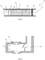
- FIG. 1 shows a schematic representation of an aerosol generating system 10.
- the aerosol generating system 10 comprises a housing 12 with an airflow inlet 14 and an airflow outlet 16.
- a power supply 13 and control unit 18 Within the housing 12 is a power supply 13 and control unit 18, a reservoir 20 of liquid aerosol-forming substrate 21, an aerosol generator 22, and a perforated plate 24.
- the aerosol generator 22 in a first configuration is a tank 26, separate from the reservoir 20, but in fluid communication with the reservoir 20 so that liquid aerosol-forming substrate 21 can flow from the reservoir 20 to the tank 26 to be aerosolised.
- the tank 26 comprises a piezoelectric component 28 and mesh 30. Together, the piezoelectric component 28 and the mesh 30 are configured to aerosolise the liquid aerosol-forming substrate within the tank 26.
- liquid aerosol-forming substrate 21 from the reservoir 20 can enter the tank 26 through a one-way valve 32.
- the piezoelectric component 28 when the piezoelectric component 28 is excited, the piezoelectric component 28vibrates and compresses the liquid aerosol-forming substrate in the tank 26.
- the piezoelectric component 28 is excited by passing alternating electric current through the piezoelectric component 28.
- the electric current is provided by the power supply 13 and the control unit 18.
- the piezoelectric component 28 bends or flexes and the pressure in the tank 26 increases.
- the one-way valve 32 hinders or prevents the flow of liquid aerosol-forming substrate back through the one-way valve 32 and so the pressure within the tank 26 forces liquid aerosol-forming substrate through the mesh 30, and out through a nozzle 34 as aerosol droplets. In this way the liquid aerosol-forming substrate 21 is aerosolised.
- the aerosol generator 22 in a second configuration is a heater assembly 36 configured to heat the liquid aerosol-forming substrate 21 so as to vaporise the liquid aerosol-forming substrate 21 and form an aerosol.
- An exemplary heater assembly 36 is shown in Figure 4 .
- the heater assembly 36 includes a wick 38 and a heater coil 40.
- the wick 38 extends into the reservoir 20 to wick liquid aerosol-forming substrate from the reservoir 20 to the heater coil 40.
- the wick 38 may be a length of absorbent material or a capillary tube to transport the liquid aerosol-forming substrate via capillary action.
- the heater coil 40 is powered by the power supply 13 and control unit 18.
- the heater coil 40 is a coil of resistive material, preferably a metal, which is resistively heated when an electrical current is passed through the heater coil 40.
- the power supply 13 and control unit 18 pass electrical current through the heater coil 40 to heat and volatise the liquid aerosol-forming substrate in the wick 38.
- the heater assembly 36 could be a resistive heater in an alternative configuration, such as a resistive mesh positioned at one end or along the length of the wick.
- the heater assembly 36 could be a resistive heater in the form of a rod or blade projecting into the reservoir 20.
- the heater assembly 36 could be a combination of a susceptor in thermal contact with a wick or projecting into the reservoir 20 and an inductor coil configured to inductively heat the susceptor.
- the aerosol generated by the aerosol generator 22 is picked up by airflow through the aerosol generating system 10 when a user draws air through the airflow outlet 16.
- the aerosol generator 22 may be controlled and powered such that aerosol is only generated when a user draws on the aerosol generating system 10.
- a pressure sensor may be incorporated into the control unit 18 to determine when a user is drawing on the aerosol generating system 10.
- the aerosol generating system further comprises a perforated plate 24 between the aerosol generator 22 and the airflow outlet 16.
- the perforated plate 24 comprises a plurality of apertures 54 extending through the perforated plate 24.
- the apertures 54 are about 10 micrometres in diameter.
- the perforated plate 24 is configured to remove or resize droplets with a diameter over 10 micrometres.
- the perforated plate 24 comprises a plurality of aligned filaments 51.
- the filaments 51 may be formed of stainless steel.
- the filaments 51 are connected to inner walls of the housing 12 so that they span across an entire width of an inner airflow channel extending between the airflow inlet 14 and the airflow outlet 16.
- the perforated plate 24 comprises a first row of aligned filaments 52 and a second row of aligned filaments 53, orthogonal to the first row to provide a grid of square apertures 54 between the filaments 51.
- the perforated plate 24 is formed from a mesh defining the plurality of apertures 54.
- the aerosol generated by the aerosol generator 22 flows through the perforated plate 24. Droplets within the aerosol that are larger than the apertures 54 are blocked by the filaments 51. In this way, the aerosol that exits the airflow outlet 16 does not include any droplets that are larger than the apertures 54.
- FIG. 6 shows a schematic representation of a second embodiment of an aerosol generating system 60.
- the second embodiment includes many of the same elements as the first embodiment, such as the housing 12 with an airflow inlet 14 and an airflow outlet 16. Like reference numerals are used to designate like parts.
- Within the housing 12 is a power supply 13 and control unit 18, a reservoir 20 of liquid aerosol-forming substrate 21 and an aerosol generator 22. Either of the configurations of aerosol generator 22 shown in Figures 2 to 4 could be used in this second embodiment of the present invention.
- the second embodiment of the aerosol generating system 60 further includes an electrode 62.
- the aerosol generated by the aerosol generator 22 passes over the electrode 62 as the droplets of aerosol flow towards the airflow outlet 16 and the droplets of aerosol are ionised or charged by the electrode 62.
- the electrode 62 may be comprise at least one of a mesh or a ring or a plate with a central hole through which an aerosol can pass. In this configuration, the aerosol is drawn through the electrode 62 by the airflow created when a user draws on the system. As the droplets of aerosol pass through the electric field created by the electrode 62 the droplets are ionised. As described herein, the droplets having a diameter above 2 micrometres are charged above their Rayleigh Limit. This ensures that droplets with a diameter above 2 micrometres break apart as the internal electrostatic forces overcome the surface tension.
- the electrode may be a nozzle 64. All aerosol generated by the aerosol generator 22 must pass through the charged nozzle 64. Therefore all droplets of the aerosol will pass through the centre of the electric field created by the electrode 64.
- the nozzle 64 directs the charged aerosol towards the airflow outlet 16 to be inhaled. Charging the droplets of the generated aerosol to a predetermined charge, chosen dependent on the liquid aerosol-forming substrate used and known as the Rayleigh Limit, ensures that droplets over a predetermined maximum size break apart as the internal electrostatic repulsive forces overcome the surface tension. Only droplets below the maximum predetermined size exit through the airflow outlet 16 to be inhaled.
- Figures 8 and 9 show schematic representations of alternatives of a third embodiment of an aerosol generating system 70.
- the aerosol is charged by an electrode 62 ( Figure 8 ) or 64 ( Figure 9 ) and also passes through a perforated plate 24 before being inhaled.
- the perforated plate 24 is electrically grounded with respect to the electrode 62 or 64. Droplets charged by the electrode 62 or 64 are therefore electrostatically attracted to the perforated plate 24 and accelerate towards the perforated plate 24.
- the potential difference between the electrode 62 or 64 and the perforated plate 24, and the distance between the electrode 62 or 64 and the perforated plate are chosen to provide an electrical field that is insufficient to cause electrical breakdown of the air between the electrode 62 or 64 and the perforated plate 24, but may be strong enough to allow droplets with a diameter over 2 micrometres to be charged to above the Rayleigh Limit.
- an aerosol generating system 80 further comprises a second reservoir 72 disposed within the housing 12. This configuration is shown in Figure 10 .
- the second reservoir 72 contains an ionisable liquid 73.
- the aerosol generator 22 ejects the liquid aerosol-forming substrate 21 and the ionisable liquid 73, in this case ethanol, through coaxial nozzles 68 and 65 respectively, as shown in Figure 11 .
- At least one of the nozzles 65, 68 forms the electrode of this configuration such that the mixture of ionisable liquid and liquid aerosol-forming substrate ejected from the nozzles 65, 68 is ionised.
- This configuration may be particularly suited when using a liquid aerosol-forming substrate that may be difficult to ionise without the addition of the ionisable liquid.
- the perforated plate 24 may be connected to the control unit 18 in such a way that any electrical current in the perforated plate 24 can be measured.
- an electrical current measuring device or circuit can be provided separately from the control unit 18. As charged droplets pass through the perforated plate 24, the droplets impart their charge to the grounded perforated plate 24, which will create a current in the perforated plate 24. Therefore, by measuring the current in the perforated plate 24, the rate of droplets passing through the array can be determined.
Landscapes
- Health & Medical Sciences (AREA)
- Engineering & Computer Science (AREA)
- General Health & Medical Sciences (AREA)
- Public Health (AREA)
- Anesthesiology (AREA)
- Biomedical Technology (AREA)
- Heart & Thoracic Surgery (AREA)
- Hematology (AREA)
- Life Sciences & Earth Sciences (AREA)
- Animal Behavior & Ethology (AREA)
- Veterinary Medicine (AREA)
- Pulmonology (AREA)
- Bioinformatics & Cheminformatics (AREA)
- Chemical & Material Sciences (AREA)
- Dispersion Chemistry (AREA)
- Electrostatic Spraying Apparatus (AREA)
- Disinfection, Sterilisation Or Deodorisation Of Air (AREA)
- Catching Or Destruction (AREA)
- Special Spraying Apparatus (AREA)
- Medicinal Preparation (AREA)
Claims (13)
- Aerosolerzeugungssystem (10), aufweisendein Gehäuse (12), das einen Luftstromauslass (16) definiert;ein flüssiges aerosolbildendes Substrat (21);einen Aerosolerzeuger (22), ausgelegt zum Erzeugen eines Aerosols aus dem flüssigen aerosolbildenden Substrat (21);eine zwischen dem Aerosolerzeuger (22) und dem Luftstromauslass (16) angeordnete perforierte Platte (24), wobei die perforierte Platte (24) eine Vielzahl von sich durch die perforierte Platte (24) erstreckenden Öffnungen (54) definiert; undeine zwischen dem Aerosolerzeuger (22) und der perforierten Platte (24) angeordnete Elektrode (62), wobei die perforierte Platte (24) elektrisch leitfähig ist und wobei das Aerosolerzeugungssystem (10) zum Erzeugen einer elektrischen Potentialdifferenz zwischen der Elektrode (62) und der perforierten Platte (24) ausgelegt ist.
- Aerosolerzeugungssystem (10) nach Anspruch 1, wobei die perforierte Platte (24) aus einer ersten Vielzahl von parallelen Filamenten (52) und einer zweiten Vielzahl von parallelen Filamenten (53) gebildet ist, wobei die erste Vielzahl von Filamenten (52) orthogonal zu der zweiten Vielzahl von Filamenten (53) ist, sodass die Vielzahl von Öffnungen (54) ein Gitter von Öffnungen (54) ist.
- Aerosolerzeugungssystem (10) nach Anspruch 1 oder 2, wobei das Aerosolerzeugungssystem (10) zum Erzeugen einer elektrischen Potentialdifferenz zwischen der Elektrode (62) und der perforierten Platte (24) von 0,5 Kilovolt bis 30 Kilovolt ausgelegt ist.
- Aerosolerzeugungssystem (10) nach Anspruch 1, 2 oder 3, wobei ein Abstand zwischen der Elektrode (62) und der perforierten Platte (24) zwischen 1 Millimeter und 50 Millimeter beträgt.
- Aerosolerzeugungssystem (10) nach einem beliebigen der vorhergehenden Ansprüche, ferner umfassend einen mit der perforierten Platte (24) verbundenen Steuerkreis, der zum Ermöglichen einer Messung einer bei Gebrauch in der perforierten Platte (24) fließenden elektrischen Energie ausgelegt ist.
- Aerosolerzeugungssystem (10), aufweisendein Gehäuse (12), das einen Luftstromauslass (16) definiert;ein flüssiges aerosolbildendes Substrat (21);einer Energieversorgung (13);eine Steuerung;einen zum Erzeugen eines Aerosols aus dem flüssigen aerosolbildenden Substrat (21) ausgelegten Aerosolerzeuger (22);einen Aerosol-Ladekreis, umfassend eine Schaltungsmasse und eine für eine Fluidverbindung mit dem von dem Aerosolerzeuger erzeugten Aerosol angeordnete Elektrode, wobei die Steuerung zum Regeln einer Energieversorgung von der Energieversorgung zu der Elektrode ausgelegt ist, um die Elektrode auf eine Potentialdifferenz zwischen 0,5 Kilovolt und 30 Kilovolt in Bezug auf die Schaltungsmasse aufzuladen; undeine zwischen der Elektrode und dem Luftstromauslass angeordnete perforierte Platte (24), wobei die perforierte Platte eine Vielzahl von sich durch die perforierte Platte erstreckenden Öffnungen definiert.
- Aerosolerzeugungssystem (10) nach Anspruch 6, wobei die Elektrode (62) eine zum Leiten von Aerosol zu dem Luftstromauslass (16) ausgelegte Düse (34) ist.
- Aerosolerzeugungssystem (10) nach Anspruch 6 oder 7, wobei eine Entfernung zwischen der Elektrode (62) und der perforierten Platte (24) zwischen 1 Millimeter und 50 Millimeter beträgt.
- Aerosolerzeugungssystem (10) nach Anspruch 6, 7 oder 8, wobei die perforierte Platte (24) elektrisch mit der Schaltungsmasse verbunden ist.
- Aerosolerzeugungssystem (10) nach einem beliebigen der Ansprüche 6 bis 9, wobei die Steuerung mit der perforierten Platte (24) verbunden und zum Ermöglichen der Messung einer bei Gebrauch in der perforierten Platte (24) fließenden elektrischen Energie ausgelegt ist.
- Aerosolerzeugungssystem (10) nach einem beliebigen der Ansprüche 6 bis 10, wobei die perforierte Platte (24) aus einer ersten Vielzahl von parallelen Filamenten (52) und einer zweiten Vielzahl von parallelen Filamenten (53) gebildet ist, wobei die erste Vielzahl von Filamenten (52) orthogonal zu der zweiten Vielzahl von Filamenten (53) ist, sodass die Vielzahl von Öffnungen (54) ein Gitter von Öffnungen (54) ist.
- Aerosolerzeugungssystem (10) nach einem beliebigen der Ansprüche 6 bis 11, ferner umfassend einen das flüssige aerosolbildende Substrat (21) enthaltenden ersten Vorratsbehälter und einen zweiten Vorratsbehälter, der eine ionisierbare Flüssigkeit enthält.
- Aerosolerzeugungssystem (10) nach Anspruch 12, wobei die Elektrode (62) aus zwei koaxialen Düsen gebildet ist, die eine zum Ausstoßen eines flüssigen aerosolbildenden Substrats (21) aus dem ersten Vorratsbehälter ausgelegte erste Düse und eine zum Ausstoßen einer ionisierbaren Flüssigkeit aus dem zweiten Vorratsbehälter ausgelegte zweite Düse umfassen.
Applications Claiming Priority (2)
| Application Number | Priority Date | Filing Date | Title |
|---|---|---|---|
| EP17204740 | 2017-11-30 | ||
| PCT/EP2018/081980 WO2019105812A1 (en) | 2017-11-30 | 2018-11-20 | Systems for generating a liquid aerosol |
Publications (2)
| Publication Number | Publication Date |
|---|---|
| EP3716799A1 EP3716799A1 (de) | 2020-10-07 |
| EP3716799B1 true EP3716799B1 (de) | 2023-04-26 |
Family
ID=60543413
Family Applications (1)
| Application Number | Title | Priority Date | Filing Date |
|---|---|---|---|
| EP18803438.3A Active EP3716799B1 (de) | 2017-11-30 | 2018-11-20 | Systeme zur erzeugung eines flüssigkeitsaerosols |
Country Status (9)
| Country | Link |
|---|---|
| US (3) | US11523636B2 (de) |
| EP (1) | EP3716799B1 (de) |
| JP (1) | JP7196172B2 (de) |
| KR (1) | KR102649033B1 (de) |
| CN (1) | CN111343876B (de) |
| AR (1) | AR113538A1 (de) |
| BR (1) | BR112020007110A2 (de) |
| TW (1) | TW201924550A (de) |
| WO (1) | WO2019105812A1 (de) |
Families Citing this family (19)
| Publication number | Priority date | Publication date | Assignee | Title |
|---|---|---|---|---|
| CN105476072B (zh) * | 2016-01-14 | 2020-06-12 | 卓尔悦欧洲控股有限公司 | 雾化头、雾化器及其电子烟 |
| WO2017207418A1 (en) * | 2016-05-31 | 2017-12-07 | Philip Morris Products S.A. | Aerosol generating device with multiple heaters |
| CN111343876B (zh) * | 2017-11-30 | 2023-06-06 | 菲利普莫里斯生产公司 | 用于生成液体气溶胶的系统 |
| CA3118713A1 (en) * | 2018-11-05 | 2020-05-14 | Juul Labs, Inc. | Cartridges for vaporizer devices |
| EP3954415A4 (de) * | 2019-04-09 | 2023-01-04 | Japan Tobacco Inc. | Aerosolzuführvorrichtung |
| US11690405B2 (en) * | 2019-04-25 | 2023-07-04 | Rai Strategic Holdings, Inc. | Artificial intelligence in an aerosol delivery device |
| JP7547462B2 (ja) | 2019-08-14 | 2024-09-09 | フィリップ・モーリス・プロダクツ・ソシエテ・アノニム | エアロゾル発生装置および混合エアロゾルを発生する方法 |
| CA3152790A1 (en) * | 2019-09-05 | 2021-03-11 | Hexo Operations Inc. | Vaporization device with liquid management |
| US11889861B2 (en) * | 2019-09-23 | 2024-02-06 | Rai Strategic Holdings, Inc. | Arrangement of atomization assemblies for aerosol delivery device |
| NL2025368B1 (en) * | 2020-04-17 | 2021-10-26 | Gilbert Tech Bv | Electronic inhaler and method for adjusting the same. |
| NL2025366B1 (en) | 2020-04-17 | 2021-10-26 | Gilbert Tech Bv | Electronic inhaler and method for adjusting the same |
| JP2022015341A (ja) * | 2020-07-08 | 2022-01-21 | 日本たばこ産業株式会社 | エアロゾル生成装置の制御ユニット |
| KR102513572B1 (ko) * | 2020-07-09 | 2023-03-23 | 주식회사 케이티앤지 | 에어로졸 생성 장치 |
| KR20220067848A (ko) * | 2020-11-18 | 2022-05-25 | 주식회사 케이티앤지 | 에어로졸 생성 장치 및 이를 제어하는 방법 |
| CN115779203A (zh) * | 2021-09-10 | 2023-03-14 | 深圳摩尔雾化健康医疗科技有限公司 | 气溶胶产生装置 |
| WO2023035242A1 (zh) * | 2021-09-10 | 2023-03-16 | 深圳摩尔雾化健康医疗科技有限公司 | 气溶胶产生装置 |
| KR20240101956A (ko) * | 2021-12-15 | 2024-07-02 | 니뽄 다바코 산교 가부시키가이샤 | 정보 처리 장치, 정보 처리 방법 및 프로그램 |
| EP4364587A1 (de) * | 2022-11-03 | 2024-05-08 | JT International SA | Aerosolerzeugungsvorrichtung |
| WO2024133142A1 (en) * | 2022-12-21 | 2024-06-27 | Jt International S.A. | An aerosol generation device |
Citations (6)
| Publication number | Priority date | Publication date | Assignee | Title |
|---|---|---|---|---|
| US20080110454A1 (en) * | 2006-11-15 | 2008-05-15 | Perfetti & Perfetti, Llc | Device and method for delivering an aerosol drug |
| US20080230052A1 (en) * | 2007-03-22 | 2008-09-25 | Pierre Denain | Artificial smoke cigarette |
| US20150034103A1 (en) * | 2012-04-18 | 2015-02-05 | Fontem Holdings 1 B.V. | Electronic cigarette |
| WO2015026206A1 (en) * | 2013-08-23 | 2015-02-26 | Lg Electronics Inc. | Electrostatic spray device |
| US20150272216A1 (en) * | 2014-03-31 | 2015-10-01 | Westfield Limited (Ltd.) | Personal vaporizer with liquid supply by suction |
| US20170280775A1 (en) * | 2016-03-31 | 2017-10-05 | Laurent Manca | Atomizing assembly for use in an aerosol-generating system |
Family Cites Families (34)
| Publication number | Priority date | Publication date | Assignee | Title |
|---|---|---|---|---|
| US3296491A (en) * | 1961-09-19 | 1967-01-03 | Martin M Decker | Method and apparatus for producing ions and electrically-charged aerosols |
| US3232292A (en) * | 1962-10-12 | 1966-02-01 | Arizona Nucleonics Inc | Ionized aerosols |
| GB8604328D0 (en) * | 1986-02-21 | 1986-03-26 | Ici Plc | Producing spray of droplets of liquid |
| US5267555A (en) * | 1988-07-01 | 1993-12-07 | Philip Pajalich | Apparatus and method for ionizing medication containing mists |
| US5152456A (en) | 1989-12-12 | 1992-10-06 | Bespak, Plc | Dispensing apparatus having a perforate outlet member and a vibrating device |
| GB9225098D0 (en) * | 1992-12-01 | 1993-01-20 | Coffee Ronald A | Charged droplet spray mixer |
| US6880554B1 (en) * | 1992-12-22 | 2005-04-19 | Battelle Memorial Institute | Dispensing device |
| US6105571A (en) * | 1992-12-22 | 2000-08-22 | Electrosols, Ltd. | Dispensing device |
| SE504458C2 (sv) * | 1995-06-21 | 1997-02-17 | Lars Gunnar Nilsson | Inhalator för elektrisk dosering av substanser |
| US7193124B2 (en) * | 1997-07-22 | 2007-03-20 | Battelle Memorial Institute | Method for forming material |
| GB2334461B (en) * | 1998-02-20 | 2002-01-23 | Bespak Plc | Inhalation apparatus |
| US6748944B1 (en) * | 2000-05-03 | 2004-06-15 | Dellavecchia Michael Anthony | Ultrasonic dosage device and method |
| DE102004041667A1 (de) * | 2004-08-27 | 2006-03-02 | Pari GmbH Spezialisten für effektive Inhalation | Inhalationstherapievorrichtung |
| EA201000473A1 (ru) | 2005-02-02 | 2010-12-30 | Оглсби Энд Батлер Рисерч Энд Девелопмент Лимитед | Устройство для испарения испаряемого вещества |
| WO2006086655A1 (en) * | 2005-02-11 | 2006-08-17 | Battelle Memorial Institute | Ehd aerosol dispensing device and spraying method |
| US7931020B2 (en) * | 2006-02-14 | 2011-04-26 | Battelle Memorial Institute | Dissociated discharge EHD sprayer with electric field shield |
| US20080271732A1 (en) * | 2007-05-01 | 2008-11-06 | Next Safety, Inc. | Pulmonary Drug Delivery Devices Configured to Control the Size of Administered Droplets |
| CN201070558Y (zh) | 2007-05-24 | 2008-06-11 | 宜兴市紫晶环保设备有限公司 | 涡凹气浮装置 |
| JP5339842B2 (ja) * | 2008-10-06 | 2013-11-13 | キヤノン株式会社 | 吐出ヘッド及び液滴吐出装置 |
| EP2456329B1 (de) * | 2009-07-22 | 2013-05-01 | Philip Morris Products S.A. | Rauchfreies zigarettenersatzprodukt |
| US20110174304A1 (en) * | 2010-01-21 | 2011-07-21 | Triplett Ii Michael D | Electrohydrodynamic aerosolization device having a time varying voltage |
| NL2008056C2 (en) * | 2011-12-29 | 2013-07-03 | Univ Delft Tech | System and method for delivering sprayed particles by electrospraying. |
| US10292424B2 (en) * | 2013-10-31 | 2019-05-21 | Rai Strategic Holdings, Inc. | Aerosol delivery device including a pressure-based aerosol delivery mechanism |
| US9861132B2 (en) | 2013-12-31 | 2018-01-09 | Shenzhen First Union Technology Co., Ltd. | Atomizer and electronic cigarette having same |
| GB201401519D0 (en) * | 2014-01-29 | 2014-03-12 | Batmark Ltd | Aerosol-forming member |
| TWI681691B (zh) * | 2014-04-30 | 2020-01-01 | 瑞士商菲利浦莫里斯製品股份有限公司 | 電熱式氣溶膠產生系統、裝置及其控制方法 |
| CN204070558U (zh) * | 2014-07-31 | 2015-01-07 | 深圳市合元科技有限公司 | 电子烟 |
| GB2529201A (en) * | 2014-08-13 | 2016-02-17 | Batmark Ltd | Device and method |
| TWI674071B (zh) * | 2014-12-15 | 2019-10-11 | 瑞士商菲利浦莫里斯製品股份有限公司 | 氣溶膠產生系統及用於在電熱式氣溶膠產生系統內導引氣流的方法 |
| US20180056022A1 (en) * | 2015-03-21 | 2018-03-01 | James Zhou Liu | Hand-actuated dry powder inhaler and its use |
| KR102651678B1 (ko) * | 2015-03-26 | 2024-03-28 | 필립모리스 프로덕츠 에스.에이. | 히터 관리 |
| CN105747278A (zh) * | 2016-04-21 | 2016-07-13 | 深圳市合元科技有限公司 | 烟油加热装置以及雾化单元、雾化器和电子烟 |
| EP3188570B1 (de) * | 2016-04-22 | 2019-09-11 | Shenzhen First Union Technology Co., Ltd. | Zerstäuber einer elektronischen zigarette, zerstäubungskern mit keramischem heizelement und keramisches heizelement darin |
| CN111343876B (zh) * | 2017-11-30 | 2023-06-06 | 菲利普莫里斯生产公司 | 用于生成液体气溶胶的系统 |
-
2018
- 2018-11-20 CN CN201880073090.3A patent/CN111343876B/zh active Active
- 2018-11-20 BR BR112020007110-2A patent/BR112020007110A2/pt active Search and Examination
- 2018-11-20 WO PCT/EP2018/081980 patent/WO2019105812A1/en unknown
- 2018-11-20 JP JP2020524476A patent/JP7196172B2/ja active Active
- 2018-11-20 EP EP18803438.3A patent/EP3716799B1/de active Active
- 2018-11-20 KR KR1020207010957A patent/KR102649033B1/ko active IP Right Grant
- 2018-11-22 AR ARP180103423A patent/AR113538A1/es active IP Right Grant
- 2018-11-22 TW TW107141611A patent/TW201924550A/zh unknown
-
2019
- 2019-03-14 US US16/353,469 patent/US11523636B2/en active Active
-
2022
- 2022-12-06 US US18/062,179 patent/US11969021B2/en active Active
-
2024
- 2024-03-28 US US18/620,414 patent/US20240237749A1/en active Pending
Patent Citations (6)
| Publication number | Priority date | Publication date | Assignee | Title |
|---|---|---|---|---|
| US20080110454A1 (en) * | 2006-11-15 | 2008-05-15 | Perfetti & Perfetti, Llc | Device and method for delivering an aerosol drug |
| US20080230052A1 (en) * | 2007-03-22 | 2008-09-25 | Pierre Denain | Artificial smoke cigarette |
| US20150034103A1 (en) * | 2012-04-18 | 2015-02-05 | Fontem Holdings 1 B.V. | Electronic cigarette |
| WO2015026206A1 (en) * | 2013-08-23 | 2015-02-26 | Lg Electronics Inc. | Electrostatic spray device |
| US20150272216A1 (en) * | 2014-03-31 | 2015-10-01 | Westfield Limited (Ltd.) | Personal vaporizer with liquid supply by suction |
| US20170280775A1 (en) * | 2016-03-31 | 2017-10-05 | Laurent Manca | Atomizing assembly for use in an aerosol-generating system |
Also Published As
| Publication number | Publication date |
|---|---|
| US20240237749A1 (en) | 2024-07-18 |
| JP7196172B2 (ja) | 2022-12-26 |
| AR113538A1 (es) | 2020-05-13 |
| US11523636B2 (en) | 2022-12-13 |
| KR102649033B1 (ko) | 2024-03-20 |
| JP2021503883A (ja) | 2021-02-15 |
| US11969021B2 (en) | 2024-04-30 |
| CN111343876A (zh) | 2020-06-26 |
| RU2020117405A (ru) | 2021-12-30 |
| WO2019105812A1 (en) | 2019-06-06 |
| TW201924550A (zh) | 2019-07-01 |
| US20190209791A1 (en) | 2019-07-11 |
| US20230105813A1 (en) | 2023-04-06 |
| KR20200092936A (ko) | 2020-08-04 |
| RU2020117405A3 (de) | 2021-12-30 |
| CN111343876B (zh) | 2023-06-06 |
| BR112020007110A2 (pt) | 2020-09-24 |
| EP3716799A1 (de) | 2020-10-07 |
Similar Documents
| Publication | Publication Date | Title |
|---|---|---|
| EP3716799B1 (de) | Systeme zur erzeugung eines flüssigkeitsaerosols | |
| RU2616556C2 (ru) | Генерирующее аэрозоль устройство с воздушными вентиляционными соплами | |
| CN105815814B (zh) | 具有液体存储部分和改善的气流特性的吸烟系统 | |
| EP4013247B1 (de) | Aerosolerzeugungsvorrichtung und verfahren zur erzeugung eines gemischten aerosols | |
| KR20190038806A (ko) | 전자 베이핑 장치에서 벤튜리 효과로 구동되는 제제 전달 | |
| CN113015448A (zh) | 气溶胶生成系统和具有泄漏保护的筒 | |
| RU2784395C2 (ru) | Система для генерирования жидкокапельного аэрозоля (варианты) | |
| RU2809783C2 (ru) | Устройство, генерирующее аэрозоль, и способ генерирования смешанного аэрозоля | |
| CN118019465A (zh) | 具有冷凝管理特征的烟嘴 |
Legal Events
| Date | Code | Title | Description |
|---|---|---|---|
| STAA | Information on the status of an ep patent application or granted ep patent |
Free format text: STATUS: UNKNOWN |
|
| STAA | Information on the status of an ep patent application or granted ep patent |
Free format text: STATUS: THE INTERNATIONAL PUBLICATION HAS BEEN MADE |
|
| PUAI | Public reference made under article 153(3) epc to a published international application that has entered the european phase |
Free format text: ORIGINAL CODE: 0009012 |
|
| STAA | Information on the status of an ep patent application or granted ep patent |
Free format text: STATUS: REQUEST FOR EXAMINATION WAS MADE |
|
| 17P | Request for examination filed |
Effective date: 20200330 |
|
| AK | Designated contracting states |
Kind code of ref document: A1 Designated state(s): AL AT BE BG CH CY CZ DE DK EE ES FI FR GB GR HR HU IE IS IT LI LT LU LV MC MK MT NL NO PL PT RO RS SE SI SK SM TR |
|
| AX | Request for extension of the european patent |
Extension state: BA ME |
|
| DAV | Request for validation of the european patent (deleted) | ||
| DAX | Request for extension of the european patent (deleted) | ||
| REG | Reference to a national code |
Ref country code: DE Ref legal event code: R079 Ref document number: 602018048933 Country of ref document: DE Free format text: PREVIOUS MAIN CLASS: A24F0047000000 Ipc: A24F0040500000 |
|
| GRAP | Despatch of communication of intention to grant a patent |
Free format text: ORIGINAL CODE: EPIDOSNIGR1 |
|
| STAA | Information on the status of an ep patent application or granted ep patent |
Free format text: STATUS: GRANT OF PATENT IS INTENDED |
|
| RIC1 | Information provided on ipc code assigned before grant |
Ipc: A24F 40/10 20200101ALN20221028BHEP Ipc: A61M 15/06 20060101ALI20221028BHEP Ipc: A61M 11/04 20060101ALI20221028BHEP Ipc: A61M 11/00 20060101ALI20221028BHEP Ipc: A61M 15/02 20060101ALI20221028BHEP Ipc: A24F 40/485 20200101ALI20221028BHEP Ipc: A24F 40/50 20200101AFI20221028BHEP |
|
| INTG | Intention to grant announced |
Effective date: 20221128 |
|
| GRAS | Grant fee paid |
Free format text: ORIGINAL CODE: EPIDOSNIGR3 |
|
| GRAA | (expected) grant |
Free format text: ORIGINAL CODE: 0009210 |
|
| STAA | Information on the status of an ep patent application or granted ep patent |
Free format text: STATUS: THE PATENT HAS BEEN GRANTED |
|
| AK | Designated contracting states |
Kind code of ref document: B1 Designated state(s): AL AT BE BG CH CY CZ DE DK EE ES FI FR GB GR HR HU IE IS IT LI LT LU LV MC MK MT NL NO PL PT RO RS SE SI SK SM TR |
|
| REG | Reference to a national code |
Ref country code: GB Ref legal event code: FG4D |
|
| REG | Reference to a national code |
Ref country code: CH Ref legal event code: EP |
|
| REG | Reference to a national code |
Ref country code: DE Ref legal event code: R096 Ref document number: 602018048933 Country of ref document: DE |
|
| REG | Reference to a national code |
Ref country code: AT Ref legal event code: REF Ref document number: 1562214 Country of ref document: AT Kind code of ref document: T Effective date: 20230515 |
|
| REG | Reference to a national code |
Ref country code: IE Ref legal event code: FG4D |
|
| REG | Reference to a national code |
Ref country code: NL Ref legal event code: FP |
|
| P01 | Opt-out of the competence of the unified patent court (upc) registered |
Effective date: 20230529 |
|
| REG | Reference to a national code |
Ref country code: LT Ref legal event code: MG9D |
|
| REG | Reference to a national code |
Ref country code: AT Ref legal event code: MK05 Ref document number: 1562214 Country of ref document: AT Kind code of ref document: T Effective date: 20230426 |
|
| PG25 | Lapsed in a contracting state [announced via postgrant information from national office to epo] |
Ref country code: SE Free format text: LAPSE BECAUSE OF FAILURE TO SUBMIT A TRANSLATION OF THE DESCRIPTION OR TO PAY THE FEE WITHIN THE PRESCRIBED TIME-LIMIT Effective date: 20230426 Ref country code: PT Free format text: LAPSE BECAUSE OF FAILURE TO SUBMIT A TRANSLATION OF THE DESCRIPTION OR TO PAY THE FEE WITHIN THE PRESCRIBED TIME-LIMIT Effective date: 20230828 Ref country code: NO Free format text: LAPSE BECAUSE OF FAILURE TO SUBMIT A TRANSLATION OF THE DESCRIPTION OR TO PAY THE FEE WITHIN THE PRESCRIBED TIME-LIMIT Effective date: 20230726 Ref country code: ES Free format text: LAPSE BECAUSE OF FAILURE TO SUBMIT A TRANSLATION OF THE DESCRIPTION OR TO PAY THE FEE WITHIN THE PRESCRIBED TIME-LIMIT Effective date: 20230426 Ref country code: AT Free format text: LAPSE BECAUSE OF FAILURE TO SUBMIT A TRANSLATION OF THE DESCRIPTION OR TO PAY THE FEE WITHIN THE PRESCRIBED TIME-LIMIT Effective date: 20230426 |
|
| PG25 | Lapsed in a contracting state [announced via postgrant information from national office to epo] |
Ref country code: RS Free format text: LAPSE BECAUSE OF FAILURE TO SUBMIT A TRANSLATION OF THE DESCRIPTION OR TO PAY THE FEE WITHIN THE PRESCRIBED TIME-LIMIT Effective date: 20230426 Ref country code: PL Free format text: LAPSE BECAUSE OF FAILURE TO SUBMIT A TRANSLATION OF THE DESCRIPTION OR TO PAY THE FEE WITHIN THE PRESCRIBED TIME-LIMIT Effective date: 20230426 Ref country code: LV Free format text: LAPSE BECAUSE OF FAILURE TO SUBMIT A TRANSLATION OF THE DESCRIPTION OR TO PAY THE FEE WITHIN THE PRESCRIBED TIME-LIMIT Effective date: 20230426 Ref country code: LT Free format text: LAPSE BECAUSE OF FAILURE TO SUBMIT A TRANSLATION OF THE DESCRIPTION OR TO PAY THE FEE WITHIN THE PRESCRIBED TIME-LIMIT Effective date: 20230426 Ref country code: IS Free format text: LAPSE BECAUSE OF FAILURE TO SUBMIT A TRANSLATION OF THE DESCRIPTION OR TO PAY THE FEE WITHIN THE PRESCRIBED TIME-LIMIT Effective date: 20230826 Ref country code: HR Free format text: LAPSE BECAUSE OF FAILURE TO SUBMIT A TRANSLATION OF THE DESCRIPTION OR TO PAY THE FEE WITHIN THE PRESCRIBED TIME-LIMIT Effective date: 20230426 Ref country code: GR Free format text: LAPSE BECAUSE OF FAILURE TO SUBMIT A TRANSLATION OF THE DESCRIPTION OR TO PAY THE FEE WITHIN THE PRESCRIBED TIME-LIMIT Effective date: 20230727 |
|
| PG25 | Lapsed in a contracting state [announced via postgrant information from national office to epo] |
Ref country code: FI Free format text: LAPSE BECAUSE OF FAILURE TO SUBMIT A TRANSLATION OF THE DESCRIPTION OR TO PAY THE FEE WITHIN THE PRESCRIBED TIME-LIMIT Effective date: 20230426 |
|
| PGFP | Annual fee paid to national office [announced via postgrant information from national office to epo] |
Ref country code: NL Payment date: 20231120 Year of fee payment: 6 |
|
| PG25 | Lapsed in a contracting state [announced via postgrant information from national office to epo] |
Ref country code: SK Free format text: LAPSE BECAUSE OF FAILURE TO SUBMIT A TRANSLATION OF THE DESCRIPTION OR TO PAY THE FEE WITHIN THE PRESCRIBED TIME-LIMIT Effective date: 20230426 |
|
| PGFP | Annual fee paid to national office [announced via postgrant information from national office to epo] |
Ref country code: GB Payment date: 20231123 Year of fee payment: 6 |
|
| REG | Reference to a national code |
Ref country code: DE Ref legal event code: R097 Ref document number: 602018048933 Country of ref document: DE |
|
| PG25 | Lapsed in a contracting state [announced via postgrant information from national office to epo] |
Ref country code: SM Free format text: LAPSE BECAUSE OF FAILURE TO SUBMIT A TRANSLATION OF THE DESCRIPTION OR TO PAY THE FEE WITHIN THE PRESCRIBED TIME-LIMIT Effective date: 20230426 Ref country code: SK Free format text: LAPSE BECAUSE OF FAILURE TO SUBMIT A TRANSLATION OF THE DESCRIPTION OR TO PAY THE FEE WITHIN THE PRESCRIBED TIME-LIMIT Effective date: 20230426 Ref country code: RO Free format text: LAPSE BECAUSE OF FAILURE TO SUBMIT A TRANSLATION OF THE DESCRIPTION OR TO PAY THE FEE WITHIN THE PRESCRIBED TIME-LIMIT Effective date: 20230426 Ref country code: EE Free format text: LAPSE BECAUSE OF FAILURE TO SUBMIT A TRANSLATION OF THE DESCRIPTION OR TO PAY THE FEE WITHIN THE PRESCRIBED TIME-LIMIT Effective date: 20230426 Ref country code: DK Free format text: LAPSE BECAUSE OF FAILURE TO SUBMIT A TRANSLATION OF THE DESCRIPTION OR TO PAY THE FEE WITHIN THE PRESCRIBED TIME-LIMIT Effective date: 20230426 Ref country code: CZ Free format text: LAPSE BECAUSE OF FAILURE TO SUBMIT A TRANSLATION OF THE DESCRIPTION OR TO PAY THE FEE WITHIN THE PRESCRIBED TIME-LIMIT Effective date: 20230426 |
|
| PGFP | Annual fee paid to national office [announced via postgrant information from national office to epo] |
Ref country code: IT Payment date: 20231120 Year of fee payment: 6 Ref country code: FR Payment date: 20231120 Year of fee payment: 6 Ref country code: DE Payment date: 20231121 Year of fee payment: 6 Ref country code: CH Payment date: 20231201 Year of fee payment: 6 |
|
| PLBE | No opposition filed within time limit |
Free format text: ORIGINAL CODE: 0009261 |
|
| STAA | Information on the status of an ep patent application or granted ep patent |
Free format text: STATUS: NO OPPOSITION FILED WITHIN TIME LIMIT |
|
| 26N | No opposition filed |
Effective date: 20240129 |
|
| PG25 | Lapsed in a contracting state [announced via postgrant information from national office to epo] |
Ref country code: SI Free format text: LAPSE BECAUSE OF FAILURE TO SUBMIT A TRANSLATION OF THE DESCRIPTION OR TO PAY THE FEE WITHIN THE PRESCRIBED TIME-LIMIT Effective date: 20230426 |
|
| PG25 | Lapsed in a contracting state [announced via postgrant information from national office to epo] |
Ref country code: SI Free format text: LAPSE BECAUSE OF FAILURE TO SUBMIT A TRANSLATION OF THE DESCRIPTION OR TO PAY THE FEE WITHIN THE PRESCRIBED TIME-LIMIT Effective date: 20230426 |
|
| PG25 | Lapsed in a contracting state [announced via postgrant information from national office to epo] |
Ref country code: MC Free format text: LAPSE BECAUSE OF FAILURE TO SUBMIT A TRANSLATION OF THE DESCRIPTION OR TO PAY THE FEE WITHIN THE PRESCRIBED TIME-LIMIT Effective date: 20230426 |
|
| PG25 | Lapsed in a contracting state [announced via postgrant information from national office to epo] |
Ref country code: LU Free format text: LAPSE BECAUSE OF NON-PAYMENT OF DUE FEES Effective date: 20231120 |
|
| PG25 | Lapsed in a contracting state [announced via postgrant information from national office to epo] |
Ref country code: MC Free format text: LAPSE BECAUSE OF FAILURE TO SUBMIT A TRANSLATION OF THE DESCRIPTION OR TO PAY THE FEE WITHIN THE PRESCRIBED TIME-LIMIT Effective date: 20230426 Ref country code: LU Free format text: LAPSE BECAUSE OF NON-PAYMENT OF DUE FEES Effective date: 20231120 |
|
| REG | Reference to a national code |
Ref country code: BE Ref legal event code: MM Effective date: 20231130 |