EP3716466A1 - Vibration actuator and driving device - Google Patents
Vibration actuator and driving device Download PDFInfo
- Publication number
- EP3716466A1 EP3716466A1 EP20165512.3A EP20165512A EP3716466A1 EP 3716466 A1 EP3716466 A1 EP 3716466A1 EP 20165512 A EP20165512 A EP 20165512A EP 3716466 A1 EP3716466 A1 EP 3716466A1
- Authority
- EP
- European Patent Office
- Prior art keywords
- vibrators
- vibrator
- vibration actuator
- vibration
- vibrator device
- Prior art date
- Legal status (The legal status is an assumption and is not a legal conclusion. Google has not performed a legal analysis and makes no representation as to the accuracy of the status listed.)
- Granted
Links
Images










Classifications
-
- H—ELECTRICITY
- H02—GENERATION; CONVERSION OR DISTRIBUTION OF ELECTRIC POWER
- H02N—ELECTRIC MACHINES NOT OTHERWISE PROVIDED FOR
- H02N2/00—Electric machines in general using piezoelectric effect, electrostriction or magnetostriction
- H02N2/0005—Electric machines in general using piezoelectric effect, electrostriction or magnetostriction producing non-specific motion; Details common to machines covered by H02N2/02 - H02N2/16
- H02N2/0075—Electrical details, e.g. drive or control circuits or methods
-
- H—ELECTRICITY
- H02—GENERATION; CONVERSION OR DISTRIBUTION OF ELECTRIC POWER
- H02N—ELECTRIC MACHINES NOT OTHERWISE PROVIDED FOR
- H02N2/00—Electric machines in general using piezoelectric effect, electrostriction or magnetostriction
- H02N2/02—Electric machines in general using piezoelectric effect, electrostriction or magnetostriction producing linear motion, e.g. actuators; Linear positioners ; Linear motors
- H02N2/026—Electric machines in general using piezoelectric effect, electrostriction or magnetostriction producing linear motion, e.g. actuators; Linear positioners ; Linear motors by pressing one or more vibrators against the driven body
-
- H—ELECTRICITY
- H02—GENERATION; CONVERSION OR DISTRIBUTION OF ELECTRIC POWER
- H02N—ELECTRIC MACHINES NOT OTHERWISE PROVIDED FOR
- H02N2/00—Electric machines in general using piezoelectric effect, electrostriction or magnetostriction
- H02N2/0005—Electric machines in general using piezoelectric effect, electrostriction or magnetostriction producing non-specific motion; Details common to machines covered by H02N2/02 - H02N2/16
- H02N2/001—Driving devices, e.g. vibrators
- H02N2/003—Driving devices, e.g. vibrators using longitudinal or radial modes combined with bending modes
- H02N2/004—Rectangular vibrators
-
- H—ELECTRICITY
- H02—GENERATION; CONVERSION OR DISTRIBUTION OF ELECTRIC POWER
- H02N—ELECTRIC MACHINES NOT OTHERWISE PROVIDED FOR
- H02N2/00—Electric machines in general using piezoelectric effect, electrostriction or magnetostriction
- H02N2/02—Electric machines in general using piezoelectric effect, electrostriction or magnetostriction producing linear motion, e.g. actuators; Linear positioners ; Linear motors
- H02N2/06—Drive circuits; Control arrangements or methods
-
- H—ELECTRICITY
- H02—GENERATION; CONVERSION OR DISTRIBUTION OF ELECTRIC POWER
- H02N—ELECTRIC MACHINES NOT OTHERWISE PROVIDED FOR
- H02N2/00—Electric machines in general using piezoelectric effect, electrostriction or magnetostriction
- H02N2/02—Electric machines in general using piezoelectric effect, electrostriction or magnetostriction producing linear motion, e.g. actuators; Linear positioners ; Linear motors
- H02N2/06—Drive circuits; Control arrangements or methods
- H02N2/065—Large signal circuits, e.g. final stages
-
- H—ELECTRICITY
- H02—GENERATION; CONVERSION OR DISTRIBUTION OF ELECTRIC POWER
- H02N—ELECTRIC MACHINES NOT OTHERWISE PROVIDED FOR
- H02N2/00—Electric machines in general using piezoelectric effect, electrostriction or magnetostriction
- H02N2/10—Electric machines in general using piezoelectric effect, electrostriction or magnetostriction producing rotary motion, e.g. rotary motors
- H02N2/12—Constructional details
-
- H—ELECTRICITY
- H02—GENERATION; CONVERSION OR DISTRIBUTION OF ELECTRIC POWER
- H02N—ELECTRIC MACHINES NOT OTHERWISE PROVIDED FOR
- H02N2/00—Electric machines in general using piezoelectric effect, electrostriction or magnetostriction
- H02N2/10—Electric machines in general using piezoelectric effect, electrostriction or magnetostriction producing rotary motion, e.g. rotary motors
- H02N2/14—Drive circuits; Control arrangements or methods
- H02N2/142—Small signal circuits; Means for controlling position or derived quantities, e.g. speed, torque, starting, stopping, reversing
-
- H—ELECTRICITY
- H02—GENERATION; CONVERSION OR DISTRIBUTION OF ELECTRIC POWER
- H02N—ELECTRIC MACHINES NOT OTHERWISE PROVIDED FOR
- H02N2/00—Electric machines in general using piezoelectric effect, electrostriction or magnetostriction
- H02N2/10—Electric machines in general using piezoelectric effect, electrostriction or magnetostriction producing rotary motion, e.g. rotary motors
- H02N2/14—Drive circuits; Control arrangements or methods
- H02N2/145—Large signal circuits, e.g. final stages
-
- H—ELECTRICITY
- H02—GENERATION; CONVERSION OR DISTRIBUTION OF ELECTRIC POWER
- H02N—ELECTRIC MACHINES NOT OTHERWISE PROVIDED FOR
- H02N2/00—Electric machines in general using piezoelectric effect, electrostriction or magnetostriction
- H02N2/10—Electric machines in general using piezoelectric effect, electrostriction or magnetostriction producing rotary motion, e.g. rotary motors
- H02N2/14—Drive circuits; Control arrangements or methods
- H02N2/145—Large signal circuits, e.g. final stages
- H02N2/147—Multi-phase circuits
-
- H—ELECTRICITY
- H10—SEMICONDUCTOR DEVICES; ELECTRIC SOLID-STATE DEVICES NOT OTHERWISE PROVIDED FOR
- H10N—ELECTRIC SOLID-STATE DEVICES NOT OTHERWISE PROVIDED FOR
- H10N30/00—Piezoelectric or electrostrictive devices
- H10N30/20—Piezoelectric or electrostrictive devices with electrical input and mechanical output, e.g. functioning as actuators or vibrators
- H10N30/202—Piezoelectric or electrostrictive devices with electrical input and mechanical output, e.g. functioning as actuators or vibrators using longitudinal or thickness displacement combined with bending, shear or torsion displacement
- H10N30/2023—Piezoelectric or electrostrictive devices with electrical input and mechanical output, e.g. functioning as actuators or vibrators using longitudinal or thickness displacement combined with bending, shear or torsion displacement having polygonal or rectangular shape
-
- H—ELECTRICITY
- H10—SEMICONDUCTOR DEVICES; ELECTRIC SOLID-STATE DEVICES NOT OTHERWISE PROVIDED FOR
- H10N—ELECTRIC SOLID-STATE DEVICES NOT OTHERWISE PROVIDED FOR
- H10N30/00—Piezoelectric or electrostrictive devices
- H10N30/40—Piezoelectric or electrostrictive devices with electrical input and electrical output, e.g. functioning as transformers
-
- H—ELECTRICITY
- H02—GENERATION; CONVERSION OR DISTRIBUTION OF ELECTRIC POWER
- H02N—ELECTRIC MACHINES NOT OTHERWISE PROVIDED FOR
- H02N2/00—Electric machines in general using piezoelectric effect, electrostriction or magnetostriction
- H02N2/0005—Electric machines in general using piezoelectric effect, electrostriction or magnetostriction producing non-specific motion; Details common to machines covered by H02N2/02 - H02N2/16
- H02N2/001—Driving devices, e.g. vibrators
- H02N2/0015—Driving devices, e.g. vibrators using only bending modes
-
- H—ELECTRICITY
- H02—GENERATION; CONVERSION OR DISTRIBUTION OF ELECTRIC POWER
- H02N—ELECTRIC MACHINES NOT OTHERWISE PROVIDED FOR
- H02N2/00—Electric machines in general using piezoelectric effect, electrostriction or magnetostriction
- H02N2/02—Electric machines in general using piezoelectric effect, electrostriction or magnetostriction producing linear motion, e.g. actuators; Linear positioners ; Linear motors
- H02N2/028—Electric machines in general using piezoelectric effect, electrostriction or magnetostriction producing linear motion, e.g. actuators; Linear positioners ; Linear motors along multiple or arbitrary translation directions, e.g. XYZ stages
-
- H—ELECTRICITY
- H02—GENERATION; CONVERSION OR DISTRIBUTION OF ELECTRIC POWER
- H02N—ELECTRIC MACHINES NOT OTHERWISE PROVIDED FOR
- H02N2/00—Electric machines in general using piezoelectric effect, electrostriction or magnetostriction
- H02N2/10—Electric machines in general using piezoelectric effect, electrostriction or magnetostriction producing rotary motion, e.g. rotary motors
- H02N2/103—Electric machines in general using piezoelectric effect, electrostriction or magnetostriction producing rotary motion, e.g. rotary motors by pressing one or more vibrators against the rotor
-
- H—ELECTRICITY
- H02—GENERATION; CONVERSION OR DISTRIBUTION OF ELECTRIC POWER
- H02N—ELECTRIC MACHINES NOT OTHERWISE PROVIDED FOR
- H02N2/00—Electric machines in general using piezoelectric effect, electrostriction or magnetostriction
- H02N2/10—Electric machines in general using piezoelectric effect, electrostriction or magnetostriction producing rotary motion, e.g. rotary motors
- H02N2/12—Constructional details
- H02N2/123—Mechanical transmission means, e.g. for gearing
-
- H—ELECTRICITY
- H02—GENERATION; CONVERSION OR DISTRIBUTION OF ELECTRIC POWER
- H02N—ELECTRIC MACHINES NOT OTHERWISE PROVIDED FOR
- H02N2/00—Electric machines in general using piezoelectric effect, electrostriction or magnetostriction
- H02N2/10—Electric machines in general using piezoelectric effect, electrostriction or magnetostriction producing rotary motion, e.g. rotary motors
- H02N2/16—Electric machines in general using piezoelectric effect, electrostriction or magnetostriction producing rotary motion, e.g. rotary motors using travelling waves, i.e. Rayleigh surface waves
- H02N2/163—Motors with ring stator
Definitions
- the present invention relates to a vibration actuator and a driving device for the vibration actuator.
- the plurality of vibrators employ electromechanical energy conversion elements, such as piezoelectric devices and electrostriction elements, and are driven by a common drive circuit. This reduces a circuit structure as compared with a case where individual drive circuits are respectively installed for the plurality of vibrators.
- a vibration driving device in which three plate-shaped vibrators are arranged at angular intervals of 120 degrees so as to drive a ring-shape driven body is proposed (see Japanese Laid-Open Patent Publication (Kokai) No. 2017-104014 ( JP 2017-104014A )).
- the vibrators of the vibration driving device of JP 2017-104014A are connected in parallel. Accordingly, since the vibrators vibrate at different amplitudes and phases because of difference in the resonance frequencies of the respective vibrators, sliding loss occurs between the vibrators and the contact member according to the vibration velocity difference between the respective vibrators. If the resonance frequencies of the vibrators are made uniform when manufacturing the vibration driving device of JP 2017-104014A , the sliding loss is reduced to some extent. However, this needs the operation to select vibrators according to the frequency and cannot eliminate the difference of the vibration velocities of the respective vibrators due to the difference in load.
- the vibrators of the driving device of JP 2008- 278712A are connected in series. Accordingly, the vibrators connected in series vibrate as one resonance system. Accordingly, vibration phases of the vibrators are made uniform to some extent. And since a balance of applied voltage depends on the amount of load, the sliding loss becomes small. However, since the resonance frequencies of the vibrators depend on the load, the difference of the vibration velocities of the vibrators cannot be eliminated.
- the present invention provides a vibration actuator and a driving device therefor that are capable of reducing difference of vibration velocities when a contact member is driven using a plurality of vibrators.
- a first aspect of the present invention provides a vibration actuator as specified in claims 1 to 13.
- a second aspect of the present invention provides a driving device for a vibration actuator as specified in claims 14 o18.
- the difference of the vibration velocities of the vibrators when the contact member is driven using a plurality of vibrators can be reduced.
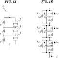
- FIG. 1A and FIG. 1B are views showing an example of a configuration of a vibrator device 10 concerning a first embodiment.
- the vibrator device 10 contacts a contact member and moves relative to the contact member. Thereby, the vibrator device 10 drives the contact member.
- FIG. 1A shows a circuit configuration in which three vibrators 1, 2, and 3 are connected in series. Piezoelectric members, electrostriction elements, etc. that are electric-mechanical energy conversion means are joined to the vibrators 1, 2, and 3.
- FIG. 1B is an equivalent circuit diagram of the vibrator device 10 in FIG. 1A .
- inductors are respectively connected in parallel to the vibrators 1, 2, and 3.
- an inductor 5 is connected in parallel to the vibrator 1
- an inductor 6 is connected in parallel to the vibrator 2
- an inductor 7 is connected in parallel to the vibrator 3.
- the inductor 5, the inductor 6, and the inductor 7 are connected in series.
- a piezoelectric member may be a lamination piezoelectric member.
- the number of the vibrators of the vibrator device 10 and the number of inductors are not limited to three.
- FIG. 2A and FIG. 2B are views showing the example of a configuration of the vibrator device of the comparative example.
- the vibrator device of the comparative example is configured by connecting three vibrators 1, 2, and 3 to which piezoelectric members are joined in series. No inductor is not connected in parallel to the vibrators 1, 2, and 3.
- FIG. 2B is an equivalent circuit diagram of FIG. 2A , and a circuit that consists of C0, L1, C1, and R1 indicates the equivalent circuit of the vibrator 1.
- a circuit that consists of C0, L2, C2, and R2 indicates the equivalent circuit of the vibrator 2.
- a circuit that consists of C0, L3, C3, and R3 indicates the equivalent circuit of the vibrator 3.
- the damping capacitance C0 of each equivalent circuit indicates the electric characteristic of the piezoelectric member that is joined to each of the vibrators 1, 2, and 3.
- the series resonant circuits that consist of Lx, Cx, and Rx (x is an integer of 1 to 3) indicates mechanical characteristics of the vibrators 1, 2, and 3.
- Reference symbols IE1, IE2, and IE3 show values of electric currents that flow through the damping capacitances C0 of the vibrators 1, 2, and 3.
- Reference symbols IM1, IM2, and IM3 show values of electric currents that flow through the series resonant circuits (Lx, Cx, and Rx) of the vibrators 1, 2, and 3. Then, a value of an electric current Io becomes equal to "IE1 + IM1", “IE2 + IM2”, and "IE3 + IM3".
- FIG. 3A and FIG. 3B are graphs showing electric current amplitude characteristics with respect to a frequency corresponding to the configuration of FIG. 2A and FIG. 2B .
- FIG. 3A is the graph showing electric current amplitude characteristics with respect to a frequency in cases where the same alternating voltages are applied to the vibrators 1, 2, and 3.
- the vibrators 1, 2, and 3 have the electric current amplitude characteristics that the amplitudes are maximized at different resonance frequencies Fr1, Fr2, and Fr3.
- FIG. 3A is the graph showing electric current amplitude characteristics with respect to a frequency corresponding to the configuration of FIG. 2A and FIG. 2B .
- FIG. 3A is the graph showing electric current amplitude characteristics with respect to a frequency in cases where the same alternating voltages are applied to the vibrators 1, 2, and 3.
- the vibrators 1, 2, and 3 have the electric current amplitude characteristics that the amplitudes are maximized at different resonance frequencies Fr1, Fr2, and Fr3.
- FIG. 3A is the graph showing electric current amplitude characteristics with
- 3B is the graph showing the amplitudes of the electric currents IM1 (an alternate long and short dash line), IM2 (a solid line), IM3 (a broken line), and Io (a dotted line) with respect to the frequency of the alternating voltage applied to the series resonant circuits (Lx, Cx, and Rx) in FIG. 2B .
- the inductors L01, L02, and L03 are respectively connected in parallel to the damping capacitances C0 of the vibrators 1, 2, and 3.
- Each inductor connected in parallel to the damping capacitance C0 resonates in parallel at a predetermined frequency. Accordingly, the amounts of the electric currents IEx' (x is an integer of 1 to 3) that flow through the parallel circuits that consist of the inductors L0x (x is an integer of 1 to 3) and the damping capacitances C0 approach zero.
- FIG. 4 is a graph showing the amplitudes of the electric currents IM1' (an alternate long and short dash line), IM2' (a solid line), IM3' (a broken line), and Io' (a dotted line) with respect to the frequency of the alternating voltage applied to the series resonant circuits (Lx, Cx, and Rx) in FIG. 1B .
- the amplitudes of the electric currents IM1', IM2', and IM3' are approximately equal and are maximized at the same resonance frequency Fr0'.
- the resonance frequency Fr0' is approximately equal to an average value of the resonance frequency Fr1 of the vibrator 1, the resonance frequency Fr2 of the vibrator 2, and the resonance frequency Fr3 of the vibrator 3.
- the amplitude of the electric current Io' becomes approximately equal to the amplitudes of the electric currents IMx' in a frequency range in which the amplitudes are more than a predetermined value.
- This embodiment employs the configuration that the inductors are connected in parallel to the respective vibrators connected in series. Accordingly, since the above-mentioned electric currents IMx'+IEx' are approximately equal to the electric currents IMx', the amplitudes and phases of the vibrators 1, 2, and 3 are made uniform even if the plurality of vibrators are vibrated with one drive voltage. This is capable of reducing the difference between the vibration velocities of the vibrators and is capable of transferring the forces generated by the respective vibrators to one contact member at a sufficient efficiency. Moreover, the contact member can be driven with the high thrust using the plurality of vibrators.
- FIG. 5A is a view showing a configuration of the vibration actuator that contacts the vibrators 1, 2, and 3 around the cylindrical shaft 4 to rotate the cylindrical shaft 4.
- FIG. 5B is a view showing the electric connection relation thereof.
- FIG. 5A is a view showing the configuration of the vibration actuator that rotates the cylindrical shaft 4.
- the vibrators 1, 2, and 3 vibrate in a vertical direction (a direction of an arrow).
- the cylindrical shaft 4 is an example of a contact member and is driven by the vibrators 1, 2, and 3.
- the vibrators 1, 2, and 3 are arranged around the cylindrical shaft 4 at nearly equal intervals of 120 degrees. Then, the vibrators 1, 2, and 3 press the cylindrical shaft 4 equally by pressure mechanisms (not shown).
- the cylindrical shaft 4 is rotated clockwise by vibrations in the vertical direction that are excited by the vibrators 1, 2, and 3.
- FIG. 5B is a view showing the electric connection relation in the vibrator device 10.
- the inductors 5, 6, and 7 are connected in parallel to the piezoelectric members joined to the vibrators 1, 2, and 3, respectively.
- the vibrator device 10 is provided with a connector 8 to input an alternating voltage.
- the vibrators 1, 2, and 3 are connected in series and both sides of a series circuit of the vibrators are connected to the connector 8.
- the vibrators 1, 2, and 3, the cylindrical shaft 4, and the inductors 5, 6, and 7 are stored in a ring-shape casing 9, and these are united to constitute the vibrator device 10.
- the vibrators 1, 2, and 3 have projection members that press the cylindrical shaft 4 that passes a hollow cylindrical part of the casing 9.
- the projection members are arranged at angular intervals of 120 degrees in the hollow cylindrical part.
- Each of the projection members is pressed to the cylindrical shaft 4 by a support member including a spring structure (not shown) at a fixed pressure.
- the projection amount and pressure of each projection member are adjustable by a rotation-linear motion conversion mechanism that is provided in the casing 9.
- FIG. 6 is a graph showing relationships between a rotation angle and amplitudes of alternating voltages applied to the respective vibrators 1, 2, and 3 when the cylindrical shaft 4 is driven by applying the alternating voltages to the vibrator device 10.
- Load fluctuation of one cycle occurs in synchronization with the rotation of the cylindrical shaft 4 because of load fluctuation under the influence of decentering of the cylindrical shaft 4. Accordingly, the voltage amplitude increases with increasing of the load, and the voltage amplitude decreases with decreasing of the load.
- the vibrator device 10 of this embodiment includes the inductors connected in parallel to the respective vibrators 1, 2, and 3, the amplitudes and phases of the electric currents flowing through the vibrators 1, 2, and 3 are made uniform, which reduces the difference of the vibration velocities of the vibrators. Thereby, even if a difference in the resonance frequency occurs between the vibrators 1, 2, and 3 or the load fluctuation occurs, the amplitudes of the alternating voltages applied are automatically adjusted. As a result, the vibration velocities of the vibrators 1, 2, and 3 are made uniform and the cylindrical shaft 4 can be driven at high efficiency.
- FIG. 7 is a view showing an example of a drive circuit for the vibration actuator that uses the vibrator device 10 concerning the first embodiment.
- the drive circuit for the vibration actuator corresponds to the driving device for the vibration actuator.
- the drive circuit for the vibration actuator shown in FIG. 7 has the vibrator device 10, a drive signal generator 13, a resistance 14, an amplitude detector 15, a comparator 16, and a drive signal controller 17.
- the vibrator device 10 corresponds to a part surrounded by a dotted line in FIG. 7 .
- the vibrators 1, 2, and 3 are connected in series.
- the inductor 5 is connected in parallel to the vibrator 1
- the inductor 6 is connected in parallel to the vibrator 2
- the inductor 7 is connected in parallel to the vibrator 3.
- the drive signal generator 13 generates the alternating voltage applied to the vibrator device 10.
- the resistance 14 is connected to the vibrator device 10 in order to measure the electric current that flows through the vibrator device 10.
- the resistance 14 outputs the voltage proportional to the vibration velocity of the vibrators 1, 2, and 3.
- the vibration amplitude of the vibrator is proportional to a value obtained by integrating the vibration velocity by time in fact, the following description assumes that the vibration amplitude shall be controlled by controlling the amplitude of the vibration velocity because the amplitude of the vibration velocity is approximately proportional to the vibration amplitude.
- the amplitude detector 15 detects the amplitude of the vibration velocity detected by the resistance 14.
- the comparator 16 compares a vibration amplitude command from a vibration amplitude command unit (not shown) with the output from the amplitude detector 15, and outputs a comparison result to the drive signal controller 17.
- the drive signal controller 17 controls the drive signal generator 13 on the basis of the comparison result which the comparing unit 16 outputted.
- the drive signal controller 17 outputs a frequency command or an amplitude command to the drive signal generator 13.
- the electric current that flows through the vibrator device 10 is approximately proportional to the vibration velocity of the vibrators 1, 2, and 3 owing to the effects of the inductors 5, 6, and 7. Since the resistance 14 detects the electric current that flows through the vibrator device 10 and the drive signal controller 17 controls the alternating signal, the amplitudes of the vibrators 1, 2, and 3 are stably controlled with quick response.
- a parallel circuit consisting of an inductor and a capacitor may be connected in parallel to each vibrator.
- a plurality of inductors that are connected in series or parallel may be connected in parallel to each vibrator in order to enable frequency matching at high accuracy.
- a capacitor may be added in parallel to the damping capacitance C0 instead of adjusting an inductor so as to adjust the value of the damping capacitance C0. This reduces enlargement of the vibrator device 10.
- the vibrator device 10 Since the inductors 5, 6, and 7 are connected in series, the vibrator device 10 is able to continue to drive a contact member (for example, the cylindrical shaft 4), even if failure, such as a short circuit or disconnection, occurs in the vibrators 1, 2, and 3. Even if a part of the vibrators 1, 2, and 3 in FIG. 7 short-circuits electrically, the alternating voltage is continuously applied to the other vibrators. Since the short-circuited vibrator stops vibration, the loads to the other vibrators become heavy for that. Since the number of the available vibrators decreases, a thrust lower if the applied voltage does not change. In the meantime, when the number of available vibrators decreases, feedback control that increases the voltage applied to the available vibrators so as to maintain the thrust starts automatically. Thereby, the drive control of the vibrator device 10 is continuable.
- a contact member for example, the cylindrical shaft 4
- the electric current that flows through the vibrator device 10 increases as compared with the case where neither short circuit nor disconnection occurs.
- the resistance 14 is measuring the electric current that flows through the vibrator device 10.
- occurrence of failure such as short circuit and disconnection is detected.
- the amplitude detector 15 detects that failure occurs in the vibrator device 10.
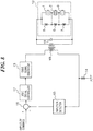
- FIG. 8 is a view showing an example of a drive circuit for a vibration actuator that is configured by adding a transformer 18 to the circuit of FIG. 7 .
- the transformer 18 as an amplifier circuit is a boosting transformer and is connected to the output side of the drive signal generator 13.
- a capacitor 19 for frequency matching is connected in parallel to a secondary side of the transformer 18.
- the electric current that is approximately proportional to a secondary-side current flows at a primary side of the transformer 18 within the driving frequency range mentioned above. Accordingly, the same operation as FIG. 7 is achievable by detecting the primary-side current of the transformer 18 by the resistance 14 like the drive circuit of FIG. 7 .
- FIG. 9 is a view showing another configuration example of the vibrator device 10 of FIG. 8 .
- the transformer 18 and the capacitor 19 are built in the vibrator device 10. Since the transformer 18 is built in the input side of the vibrator device 10, the vibrator device 10 can be driven at relatively low voltage.
- FIG. 10A and FIG. 10B are views showing examples of the vibration actuators concerning the first embodiment.
- FIG. 10A is a view showing an example of the vibration actuator that is constituted by connecting three vibrator devices 10, 11, and 12 in series.
- FIG. 10B is a view showing an example of the vibration actuator that is constituted by connecting the three vibrator devices 10, 11, and 12 in parallel.
- the number of the vibrator devices 10 connected in series or in parallel is not limited to three. Since one vibrator device 10 has three vibrators as mentioned above, the vibration actuator in FIG. 10A employs nine vibrators. Nine vibrators connected in series may be built in one vibrator device. In the meantime, when the vibrators are divided into a plurality of vibrator devices, there is a merit that output torque is adjusted by adjusting the number of vibrator devices according to required output torque.
- the vibrator devices 11 and 12 are the same as the vibrator device 10. Three vibrators connected in series are built in each of the vibrator devices 10, 11, and 12, and the average of the resonance frequencies of three vibrators falls within the predetermined frequency range.
- the vibrator devices 10, 11, and 12 may be manufactured manually or automatically.
- a list of resonance frequencies is created on the basis of measuring results of the resonance frequencies of the respective vibrators.
- the fixed number of vibrators are classified into some classes corresponding to the frequency ranges by referring to the resonance frequency list. For example, the fixed number of vibrators are classified every 500 Hz.
- three vibrators are selected at random from the same class and the average of the resonance frequencies of the three vibrators is calculated.
- Random selection of three vibrators is repeated until obtaining a combination of three vibrators of which the average of resonance frequencies falls within a frequency range (for example, a predetermined frequency ⁇ 25 Hz) that is beforehand decided for every class.
- a frequency range for example, a predetermined frequency ⁇ 25 Hz
- one vibrator device is constituted by these three vibrators.
- vibrators that constitute one vibrator device may be selected using dispersion of resonance frequencies instead of the average. That is, in this case, vibrators of which the dispersion of the resonance frequencies falls within a predetermined dispersion range are built in one vibrator device.
- the dispersion is set to a large value to some extent, there is unevenness of the resonance frequencies of the selected vibrators, which stabilizes the characteristic of the vibrator device.
- a vibration actuator is constituted by combining a plurality of vibrator devices of the same class, a high-power and high-efficiency vibration actuator is manufactured stably.
- the three vibrator devices 10, 11, and 12 are connected in series.
- the number of the vibrator devices connected in series increases, it is necessary to enlarge the amplitude of the alternating voltage, which increases the applied voltage.
- the applied voltage becomes high, the entire vibrator device is enlarged for applying an insulation countermeasure etc. This increases a cost.
- the configuration in which the vibrator devices 10, 11, and 12 are connected in parallel can be employed as shown in FIG. 10B .
- the vibrator devices are driven by the alternating voltage of the amplitude that is one third of the amplitude of the case where the three vibrator devices 10, 11, and 12 are connected in series.
- the vibrator devices 10, 11, and 12 belong in the same class as mentioned above, the resonance frequencies (averages of the resonance frequencies of the built-in vibrators) of the vibrator devices are approximately equal. Moreover, since the three vibrators are equally arranged around the cylindrical shaft 4, the loads of three vibrators are equalized. Accordingly, there is little load fluctuation during rotation. This reduces the difference between the vibration velocities of the vibrator devices and achieves efficient drive.
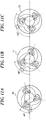
- FIG. 11A, FIG. 11B, and FIG. 11C are views showing attachment phases of the respective vibrator devices 10, 11, and 12 to the cylindrical shaft 4.
- the three vibrator devices are attached so that the rotation phases are shifted every 40 degrees. Since the vibrator devices 10, 11, and 12 are equally arranged around the cylindrical shaft 4 by shifting the phases by the predetermined angle as shown in FIG. 11A, FIG. 11B, and FIG. 11C , rotation of the cylindrical shaft 4 with few torque fluctuation is achieved.
- the three vibrators are connected in series in each of the vibrator devices 10, 11, and 12 in the example shown in FIG. 11A, FIG. 11B, and FIG. 11C , the vibrators are arranged every 120 degrees. When the vibrator device has two vibrators, two vibrators are preferably arranged every 180 degrees. Moreover, when the vibrator device has four vibrators, four vibrators are preferably arranged every 90 degrees.
- FIG. 12 is a view showing a drive circuit for the three vibration actuators of FIG. 10B .
- Each of the vibrator devices 10, 11, and 12 has three vibrators connected in series and inductors connected in parallel to the three vibrators.
- the value of the inductor connected in parallel to each vibrator is matched at a predetermined frequency within the frequency range of the alternating voltage that the drive signal generator 13 outputs. That is, a relation between the matching frequency F0, the damping capacitance C0, and the value L0 of the inductor is represented by the above-mentioned formula 1.
- the drive signal generator 13 generates the alternating voltage applied to the vibrator devices 10, 11, and 12.
- the resistance 14 is used to measure the total electric current that flows through the vibrator devices 10, 11, and 12. Since the resonance frequencies of the vibrator devices 10, 11, and 12 are made uniform, an almost equivalent average load is applied to each of the vibrators that are equally arranged around the cylindrical shaft 4. Accordingly, the phase of inflow electric current does not deviate largely.
- the amplitude detector 15 outputs the voltage proportional to the sum of the amplitudes of electric currents that flow through the vibrator devices 10, 11, and 12. Then, the comparator 16 compares the sum of the amplitudes of electric currents with the vibration amplitude command from the command unit (not shown).
- the drive signal controller 17 controls the frequency or amplitude of the alternating voltage that the drive signal generator 13 outputs on the basis of the comparison result.
- the plurality of vibrator devices may respectively drive different contact members.
- the circuit structure can be reduced because the plurality of contact members are simultaneously driven at the similar vibration velocities.
- the vibrators of the same configuration may be applied to each vibrator device as long as the resonance frequencies of the vibrators fall within the predetermined range.
- FIG. 10A and FIG. 10B respectively show the vibration actuators in which the plurality of vibrator devices 10, 11, and 12 are connected in series and in parallel.
- Conditions of the contact member may differ according to the positions that the vibrator devices 10, 11, and 12 contact.
- the diameter of the cylindrical shaft 4 may differ according to the positions that the vibrator devices 10, 11, and 12 contact.
- the configuration that the transformer 18 is provided inside each of the vibrator devices 10, 11, and 12 as shown in FIG. 9 is employed.
- the ratio of the vibration velocities is adjusted by adjusting the winding ratios of the transformers 18. That is, the vibration velocity of each of the vibrator devices 10, 11, and 12 is properly controlled by changing the winding ratio of each of the transformers 18 according to the condition of the contact member.
- FIG. 13 is a view showing an example of a vibration actuator concerning the second embodiment.
- each of three shaft-output vibration actuators 20, 27, and 30 has one vibrator and joins to a rotation shaft 33A using a bevel gear mechanism to rotate the rotation shaft 33A.
- a bevel gear 22 is attached at a front end of an output shaft 21 of the vibration actuator 20.
- a bevel gear 29 is attached at a front end of an output shaft 28 of the vibration actuator 27.
- a bevel gear 32 is attached at a front end of an output shaft 31 of the vibration actuator 30.
- the bevel gears 22, 29, and 32 engage with a larger bevel gear 33 attached to the rotation shaft 33A at angular intervals of 120 degrees.
- FIG. 14 is a view showing one example of a configuration of the vibration actuator 20 concerning the second embodiment.
- the vibration actuator 20 has a rotor 23, ceramic elastic body 24, piezoelectric member 25, and friction member 26.
- the output shaft 21 is joined to the center of the rotor 23.
- the output shaft 21 and rotor 23 are supported rotatably.
- the ceramic elastic body 24 is a non-conductive member that has a comb-like projection structure.
- the piezoelectric member 25 is adhered to the ceramic elastic body 24.
- the friction member 26 is adhered on the projection structure of the ceramic elastic body 24.
- the material of the friction member 26 is selected so that a contact portion to the rotor 23 slowly and stably wears out.
- FIG. 15 is a view showing an electrode structure of the circular piezoelectric member 25.
- FIG. 15 shows a connection state between electrodes 34, 35, 36, and 37 of the piezoelectric member 25 on its front surface and the drive voltage lines of the phases A, B, NA, and NB
- FIG. 16 is a view showing a wiring structure of the piezoelectric member 25. Electrodes of the piezoelectric member 25 on its back surface are also distributed as well as the electrodes 34, 35, 36, and 37 shown in FIG. 15 . A back electrode of the phase NA is opposite to the electrode 34 of the phase A. A back electrode of the phase BA is opposite to the electrode 35 of the phase B. As shown in FIG. 16 , an inductor 38 is connected in parallel between the phases A and NA and an inductor 39 is connected in parallel between the phases B and NB. The phase difference between the alternating voltages applied to the phases A and NA is equal to 180 degrees, and the phase difference between the alternating voltages applied to the phases B and NB is the same as it.
- FIG. 17 is a view showing a first example of a drive circuit for the vibration actuator concerning the second embodiment.
- the vibration actuator 20 a plurality of vibration sections of which phases are different are formed by the alternating voltages that have the phase difference of 180 degrees and are input by the phases A and NA and the phases B and NB.
- the two vibration sections of which phases are different are indicated by two vibrators in FIG. 17 .
- the inductor 38 is connected in parallel between the phases A and NA and the inductor 39 is connected in parallel between the phases B and NB.
- the vibration actuators 27 and 30 are connected similarly, and the vibration actuators 20, 27, and 30 are connected in series for each phase.
- the three vibration actuators 20, 27, and 30 are connected in series and constitute one vibration actuator 40 that has terminals A, NA, B, and NB as a whole.
- An area surrounded with a broken line indicates each vibration actuator 20, 27, and 30.
- An area surrounded by a dotted line indicates the vibration actuator 40.
- the capacitor 19 for frequency matching and the secondary side winding of the transformer 18 for amplification are connected in parallel between the terminals A and NA of the vibration actuator 40.
- the capacitor 42 for frequency matching and the secondary side winding of the transformer 41 for amplification are connected in parallel between the terminals B and NB of the vibration actuator 40.
- the drive signal generator 43 generates an alternating voltage.
- H-bridge circuits power amplification circuits, not shown) are respectively connected between the terminals A and NA and between the terminals B and NB of the drive signal generator 43.
- Waveforms of pulse drive signals that the H-bridge circuits output are shaped by series resonant circuits constituted by inductors 44 and 46 and capacitors 45 and 47 that are inserted between the transformers 18 and 41 and the drive signal generator 43. Then, the pulse drive signals after the waveform shaping are amplified by the transformers 18 and 41, and are applied to the vibration actuator 40.
- the series resonant circuits constituted by the inductors 44 and 46 and the capacitors 45 and 47 are subjected to matching adjustment at a predetermined frequency within a driving frequency range of the vibration actuator 40. This suppresses large fluctuation of the drive voltage amplitude of the vibration actuator 40 within the driving frequency range.
- Resistances 14 and 48 for current measurement are respectively connected to source terminals for electric current detection of the H-bridge circuits of the drive signal generator 43.
- the resistances 14 and 48 are measuring the electric currents corresponding to the vibration velocities of the vibrators included in the vibration actuator 40.
- the amplitude detector 15 detects the amplitude of the vibration velocities of the vibrators on the basis of the measurement values of the resistances 14 and 48.
- the comparator 16 compares the vibration amplitude command from the vibration amplitude command unit (not shown) with the detection results (amplitude velocities of the vibrators) of the amplitude detector 15.
- the drive signal controller 17 outputs at least one command among commands about the frequency, pulse width, and voltage amplitude to the drive signal generator 43 according to the comparison result.
- a vibration actuator has irregularity or fluctuation in a resonance frequency or an internal loss under the influence of manufacture irregularity of a friction member or pressure irregularity owing to plane accuracy of a vibrator.
- an inductor is connected in parallel to each of the vibrators that are connected in series in this embodiment as mentioned above. This makes the amplitude characteristics of the vibrators uniform, allows to transmit the comparatively equal force to the bevel gear 33, and enables the efficient drive with little wear of the gears.
- the vibration actuator 40 does not include the transformers 18 and 41, the inductors 44 and 46, and the capacitors 45 and 47 in the example in FIG. 17 , some or all of these components may be included in the vibration actuator 40. Since the vibration actuator 40 includes the components that are subjected to the frequency matching in accordance with the inherent resonance frequency, adjustment at the time of using the vibration actuator 40 becomes unnecessary. This reduces variation in performance and improves convenience of the user who uses the vibration actuator 40. Moreover, either of the inductor 44 and the capacitor 45 may be connected in series to the primary side of the transformer 18. Similarly, either of the inductor 46 and the capacitor 47 may be connected in series to the primary side of the transformer 41. A capacitor is used to intercept direct current and an inductor has an effect to smooth a waveform.
- the entire configuration including the three vibration actuators 30, 27, and 30 that are connected in series and are united by the bevel gear 33 is described as the one vibration actuator 40.
- the vibration actuator 40 is one vibrator device
- a configuration in which the vibrator devices are connected in series or in parallel can be also employed.
- a high-output vibration actuator is constituted.
- the average of the resonance frequencies of the vibrators in each of the vibration actuators, which constitute the vibrator devices be approximately equal to the average of the resonance frequencies of the three vibrators in the vibration actuator 40.
- the above-mentioned vibrator devices may be mechanically combined by connecting a plurality of complex vibration actuators as shown in FIG. 13 in a state where a plurality of gears equivalent to the bevel gear 33 are fixed to the same shaft 33A.
- the vibrator devices may be combined through other gears.
- FIG. 18 is a view showing a second example of a drive circuit for the vibration actuator concerning the second embodiment.
- the vibrator device 104 has the vibration actuators 20, 27, and 30 and the transformers 18 and 41.
- the vibrator device 107 has vibration actuators 101, 102, and 103 and transformers 105 and 106.
- the ratio of the rotational speeds of the vibrator devices is adjustable by changing the winding ratios of the transformers of the vibrator devices.
- the three vibration actuators 20, 27, and 30 connected in series in the vibrator device drive one shaft through the bevel gears 22, 29, and 32 in the second embodiment.
- the vibration actuators may drive different contact members, respectively.
- a plurality of vibration actuators are applicable to drive the dolls. This case is effective because the plurality of vibration actuators are stably driven at an appropriate speed.
- a doll is attached in place of the bevel gear 22 of the vibration actuator in FIG. 14 .
- the three vibration actuators to which different dolls are respectively attached are electrically connected in series, the three dolls are rotated at the almost same speed.
- the drive circuit for the vibration actuator in FIG. 18 is able to change the rotation speeds of the dolls for every vibrator device by adjusting the winding ratio of each transformer.
- the gear ratio of the engaged gears is adjusted while adjusting the winding ratio of each transformer, the adjustment depending on required torque is also available.
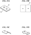
- FIG. 19A through FIG. 19D are views showing a configuration and vibration modes of a vibrator concerning the third embodiment.
- a vibrator 49 has a plate shape and is manufactured from non-conductive material. Two projections that contact a contact member are provided in the surface of the vibrator 49.
- a piezoelectric member 50 constitutes a part of the vibrator 49 and vibrates the vibrator 49.
- FIG. 19B shows electrodes 53 and 54 provided in the piezoelectric member 50.
- the electrodes 53 and 54 are electrically insulated. Two alternating voltages of which phases vary independently are respectively applied to the electrode 53 and the electrode 54.
- Two similar electrodes are also provided on a back surface of the piezoelectric member 50 and are configured so as to enable energization from the front surface through via holes (not shown) provided in parts of the electrodes 53 and 54.
- FIG. 19C shows a vibration form in a vibration mode excited when alternating voltages of the same phase are applied to the electrodes 53 and 54.
- FIG. 19D shows a vibration form of the vibration mode excited when alternating voltages of opposite phases are applied to the electrodes 53 and 54.
- the vibration mode of FIG. 19C is excited.
- the vibration mode of FIG. 19D is excited.
- phase difference of alternating voltages is an angle between 0 degrees and 180 degrees
- both the vibration modes are excited simultaneously.
- the phase difference of alternating voltages is an angle between 0 degrees and 120 degrees in many cases.
- a contact member that presses the projections provided in the vibrator 49 moves.
- the contact member is a rectangular parallelepiped
- the contact member that presses the projections provided in the vibrator 49 moves in a rectangular longitudinal direction.
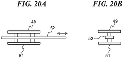
- FIG. 20A and FIG. 20B are views showing a first example of a linear-motion vibration actuator of the third embodiment.
- FIG. 20A is a figure viewed from a direction that intersects perpendicularly with a moving direction of a contact member 52. Projections of the two vibrators 49 and 51 are arranged face to face mutually and are configured so that the contact member 52 will move in a direction of an arrow in FIG. 20A in a state where the projections put the contact member 52 therebetween from the vertical direction.
- FIG. 20B is a figure viewed from the moving direction of the contact member 52.
- the vibrators 49 and 51 are arranged symmetrically in the vertical direction (are arranged equally at angular intervals of 180 degrees on the circumference) with respect to the contact member 52.
- FIG. 21 is a view showing a first example of the drive circuit for the vibration actuator concerning the third embodiment.
- the piezoelectric members of the vibrator 49 and the piezoelectric members of the vibrator 51 are connected in series for each phase, and the inductors are respectively connected in parallel to the vibrators 49 and 51.
- the vibrators 49 and 51 are connected to the H-bridge of the drive signal generator 43 through the series resonant circuit that consists of the inductors 44 and 46 and the capacitors 45 and 47.
- the series resonant circuit may consist of inductors only or capacitors only.
- the drive signal generator 43 outputs pulse signals of four phases that differ every 90 degrees.
- a thrust detector 55 detects thrust to the contact member 52 and outputs the detected thrust to a comparator 56.
- the comparator 56 compares the detected thrust with a thrust command from an command unit (not shown) and outputs a comparison result.
- a vibration amplitude command unit 57 controls the vibration amplitudes of the vibrators 49 and 51 according to the comparison result that the comparator 56 outputs.
- the resistance 14 and 48 for measuring the electric currents corresponding to the vibration velocities of the vibrators 49 and 51 are connected to the source terminals for electric current detection of the H-bridges of the drive signal generator 43.
- the amplitude detector 15 detects the vibration amplitudes from the electric currents that the resistances 14 and 48 measure.
- the comparator 16 compares the detected vibration amplitudes and the vibration amplitude command from the vibration amplitude command unit 57.
- the drive signal controller 17 controls at least one of the frequency, pulse width, and voltage amplitude of the pulse signals that the drive signal generator 43 generates according to the comparison result.
- the thrust of the vibrators 49 and 51 when the thrust of the vibrators 49 and 51 is smaller than a target value, the frequency of the alternating voltage that the drive signal generator 43 outputs approaches the resonance frequency of the vibrators 49 and 51, and the vibration amplitudes of the vibrators 49 and 51 increase. Thereby, the thrust of the vibrators 49 and 51 increases.
- the moving speed of the contact member 52 can be controlled when a configuration in which the thrust detection part 55 is replaced with a speed detector that detects the speed of the contact member 52 and the comparator 56 compares the detected speed with a speed command from a command unit (not shown) is employed.
- FIG. 22A and FIG. 22B are views showing a second example of a linear-motion vibration actuator concerning the third embodiment. As shown in FIG. 22A and FIG. 22B , four vibrators 49, 51, 62, and 63 are equally arranged around a contact member 64 that is a prism having a square section at angular intervals of 90 degrees on the circumference.
- the vibrators 49, 51, 62, and 63 shown in FIG. 22A and FIG. 22B are connected in series for each phase of the alternating voltage that is applied to two electrodes (not shown) of a piezoelectric member of each vibrator. And the inductors are respectively connected in parallel to the vibrators.
- the contact member 64 may be a cylindrical shape having a circular section.
- one vibrator device is constituted by connecting the four vibrators in series in the example of FIG. 22A and FIG. 22B
- a configuration in which two vibrator devices each of which is constituted by two vibrators that are opposite to each other are connected in series or in parallel may be employed.
- a configuration in which a plurality of vibrator devices each of which is constituted by four vibrators are arranged along the moving direction of the contact member 64 and are connected in parallel or in series may be employed.
- FIG. 23 is a view showing an example of a rotary-motion vibration actuator concerning the third embodiment.
- three vibrators 58, 59, and 60 are equally arranged along a circular contact member 61.
- the vibrators 58, 59, and 60 are electrically connected in series, and inductors are respectively connected in parallel to the vibrators 58, 59, and 60 for each phase.
- the plurality of vibrators are driving one contact member in the example of FIG. 23
- the plurality of vibrators may respectively drive different contact members.
- the respective vibrator devices may drive different contact members.
- FIG. 24 is a view showing a first example of a vibration actuator concerning the fourth embodiment.
- two vibrators 65 and 67 and two vibrators 66 and 68 respectively constitute vibrator devices.
- the vibrators 65 and 67 constitute a Y-axis vibrator device that drives a contact member 69 in a Y-axis direction.
- the vibrators 65 and 67 are electrically connected in series, and inductors are respectively connected in parallel to the vibrators 65 and 67.
- the vibrators 66 and 68 constitute an X-axis vibrator device that drives the contact member 69 in an X-axis direction.
- the vibrators 66 and 68 are electrically connected in series, and inductors are respectively connected in parallel to the vibrators 66 and 68.
- the resonance frequency of the X-axis vibrator device is fully apart from the resonance frequency of the Y-axis vibrator device so as not to affect mutually. And the shapes of the vibrators are adjusted so that the driving frequency ranges may not overlap.
- FIG. 25 is a view showing a first example of a drive circuit for the vibration actuator concerning the fourth embodiment.
- the vibrators 66 and 68 of the X-axis vibrator device and the vibrators 65 and 67 of the Y-axis vibrator device are connected in series for each phase.
- an inductor and a capacitor are connected in parallel to each vibrator.
- Values of the inductors and capacitors of the Y-axis vibrator device are subjected to frequency matching to a frequency Fy for a Y-axis.
- values of the inductors and capacitors of the X-axis vibrator device are subjected to frequency matching to a frequency Fx for an X-axis.
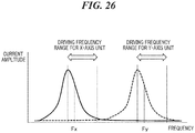
- FIG. 26 is a graph showing electric current amplitude characteristics of the vibrator devices in the fourth embodiment.
- a solid line shows the vibration characteristic of the X-axis vibrator device, and a broken line shows the vibration characteristic of the Y-axis vibrator device.
- Driving frequency ranges are set at the higher sides of the respective maximum-amplitude frequencies.
- the frequency Fx for the X-axis and the frequency Fy for the Y-axis are set within the respective driving frequency ranges.
- the drive signal generator 70 in FIG. 25 generates two-phase alternating voltages in the respective frequency ranges by compositing the alternating voltages in the two frequency ranges including the frequency Fx for the X-axis and the frequency Fy for the Y-axis, respectively.
- An amplitude detector 71 detects the vibration amplitudes in the frequency range for theX-axis and the frequency range for the Y-axis on the basis of the sum signal of the two-phase electric currents that flow according to the vibration velocities of the vibrators that the resistance 14 for current detection measures, and outputs the detection results.
- Comparators 16 and 72 respectively compare a vibration amplitude command for the X-axis and a vibration amplitude command for the Y-axis from a command unit (not shown) with the detection results that the amplitude detector 71 outputs.
- Drive signal controllers 17 and 73 respectively control the frequencies of the alternating voltages applied to the X-axis vibrator device and Y-axis vibrator device on the basis of the comparison results of the comparators 16 and 72.
- the command unit monitors position signals output from a two-dimensional position detector (not shown) that detects a two-dimensional position of the contact member 69. And the command unit compares the position signals with target positions in the respective axes. Then, the command unit switches the phases of the alternating voltages applied to the X-axis vibrator device and Y-axis vibrator device to 90 degrees or -90 degrees according to signs (+/-) of the comparison results and sets up a vibration amplitude command for the X-axis and a vibration amplitude command for the Y-axis according to the absolute values of the comparison results.
- a method of separating the signals in the two frequency ranges there are a method of separating the signals with a filter, a method of finding frequencies and amplitudes by the FFT computation, and a method of performing synchronous detection of the synchronizing signal that the drive signal generator 70 generates.
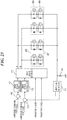
- FIG. 27 is a view showing a second example of a drive circuit for the vibration actuator concerning the fourth embodiment.
- the vibrator devices of which the driving frequency ranges differ are individually connected to the drive signal generator 70 through the transformers, respectively.
- a series circuit that consists of an inductor and a capacitor that are subjected to frequency matching at a predetermined frequency within a driving frequency range decided for each vibrator device is inserted between each transformer and the drive signal generator 70.
- FIG. 28 is a view showing a second example of the vibration actuator concerning the fourth embodiment.
- a plurality of vibrator devices 74, 75, 76, 77, and 78 shown in FIG. 28 have a plurality of vibrators connected in series and inductors connected in parallel to the respective vibrators.
- the vibrator devices 74, 75, 76, 77, and 78 are constituted by having the vibrators of which driving frequency ranges do not overlap, respectively.
- the vibrator devices 74, 75, 76, 77, and 78 are electrically connected in parallel and are driven by two-phase alternating voltages A and B.
- Each of the vibrator devices 74, 75, 76, 77, and 78 nips a linear-motion contact member with a plurality of vibrators that are electrically connected in series as with the examples shown in FIG. 20A, FIG. 20B , FIG. 22A, and FIG. 22B .
- a wire bundle 79 is combined with the contact member.
- the wire bundle 79 is engaged with a tube-shaped bending driver 80 that imitates a finger.
- the bending driver 80 is constituted so as to bend and stretch a plurality of pseudo joints by pulling and pressing wires of the wire bundle 79.
- One wire of the wire bundle 79 corresponds to each of the vibrator devices 74, 75, 76, 77, and 78.
- a wire may be configured to combine with a vibrator device so as to be relatively movable with respect to a contact member. That is, the wire is constituted to be movable by the vibrator device and contact member that move relatively and mutually.
- the bending driver 80 can be driven by linearly moving the contact members included in the vibrator devices 74, 75, 76, 77, and 78 as if a finger bends and stretches. Accordingly, since a plurality of wires are driven even if the number of wiring lines is small, it is effective in the driving of a complicated robot hand having a plurality of joints.
- a vibration actuator that is capable of reducing difference of vibration velocities when a contact member is driven using a plurality of vibrators.
- the vibration actuator includes a vibrator device and a contact member that moves relative to the vibrator device.
- the vibrator device includes a plurality of vibrators that are connected in series, and a plurality of inductors that are connected in parallel to the respective vibrators.
Landscapes
- Engineering & Computer Science (AREA)
- Power Engineering (AREA)
- General Electrical Machinery Utilizing Piezoelectricity, Electrostriction Or Magnetostriction (AREA)
Abstract
Description
- The present invention relates to a vibration actuator and a driving device for the vibration actuator.
- There is a known conventional mechanism that drives a contact member using a plurality of vibrators. The plurality of vibrators employ electromechanical energy conversion elements, such as piezoelectric devices and electrostriction elements, and are driven by a common drive circuit. This reduces a circuit structure as compared with a case where individual drive circuits are respectively installed for the plurality of vibrators. As a related technique, a vibration driving device in which three plate-shaped vibrators are arranged at angular intervals of 120 degrees so as to drive a ring-shape driven body is proposed (see Japanese Laid-Open Patent Publication (Kokai) No.
2017-104014 JP 2017-104014A kai) No. 2008-278712 JP 2008-278712A - The vibrators of the vibration driving device of
JP 2017-104014A JP 2017-104014A - In the meantime, the vibrators of the driving device of
JP 2008- 278712A - The present invention provides a vibration actuator and a driving device therefor that are capable of reducing difference of vibration velocities when a contact member is driven using a plurality of vibrators.
- Accordingly, a first aspect of the present invention provides a vibration actuator as specified in
claims 1 to 13. - Accordingly, a second aspect of the present invention provides a driving device for a vibration actuator as specified in
claims 14 o18. - According to the present invention, the difference of the vibration velocities of the vibrators when the contact member is driven using a plurality of vibrators can be reduced.
- Further features of the present invention will become apparent from the following description of exemplary embodiments with reference to the attached drawings.
-
-
FIG. 1A and FIG. 1B are views showing an example of a configuration of a vibrator device concerning a first embodiment. -
FIG. 2A and FIG. 2B are views showing an example of a configuration of a vibrator device of a comparative example. -
FIG. 3A and FIG. 3B are graphs showing electric current amplitude characteristics with respect to a frequency corresponding to the configuration ofFIG. 2A and FIG. 2B . -
FIG. 4 is a graph showing amplitude of electric current with respect to a frequency of an alternating voltage applied to the series circuit ofFIG. 1B . -
FIG. 5A is a view showing a configuration of a vibration actuator that rotates a cylindrical shaft, andFIG. 5B is a view showing an electric connection relation thereof. -
FIG. 6 is a graph showing relationships between a rotation angle and amplitudes of alternating voltages applied to the respective vibrators when the cylindrical shaft shown inFIG. 5A is driven to rotate. -
FIG. 7 is a view showing an example of a drive circuit for a vibration actuator that uses the vibrator device concerning the first embodiment. -
FIG. 8 is a view showing an example of a drive circuit for the vibration actuator that is configured by adding a transformer to the circuit ofFIG. 7 . -
FIG. 9 is a view showing another configuration example of the vibrator device ofFIG. 8 . -
FIG. 10A and FIG. 10B are views examples of vibration actuators concerning the first embodiment. -
FIG. 11A, FIG. 11B, and FIG. 11C are views showing attachment phases of the respective vibrator devices to the cylindrical shaft. -
FIG. 12 is a view showing a drive circuit for the three vibration actuators ofFIG. 10B . -
FIG. 13 is a view showing an example of a vibration actuator concerning a second embodiment. -
FIG. 14 is a view showing a configuration of the vibration actuator concerning the second embodiment. -
FIG. 15 is a view showing an electrode structure of a circular piezoelectric member. -
FIG. 16 is a view showing a wiring structure of the piezoelectric member. -
FIG. 17 is a view showing a first example of a drive circuit for the vibration actuator concerning the second embodiment. -
FIG. 18 is a view showing a second example of a drive circuit for the vibration actuator concerning the second embodiment. -
FIG. 19A through FIG. 19D are views showing a configuration and vibration modes of a vibrator concerning a third embodiment. -
FIG. 20A and FIG. 20B are views showing a first example of a linear-motion vibration actuator of the third embodiment. -
FIG. 21 is a view showing a first example of a drive circuit for the vibration actuator concerning the third embodiment. -
FIG. 22A and FIG. 22B are views showing a second example of a linear-motion vibration actuator concerning the third embodiment. -
FIG. 23 is a view showing an example of a rotary-motion vibration actuator concerning the third embodiment. -
FIG. 24 is a view showing a first example of a vibration actuator concerning a fourth embodiment. -
FIG. 25 is a view showing a first example of a drive circuit for the vibration actuator concerning the fourth embodiment. -
FIG. 26 is a graph showing electric current amplitude characteristics of the vibrator devices in the fourth embodiment. -
FIG. 27 is a view showing a second example of a drive circuit for the vibration actuator concerning the fourth embodiment. -
FIG. 28 is a view showing a second example of a vibration actuator concerning the fourth embodiment. - Hereafter, embodiments according to the present invention will be described in detail by referring to the drawings. Configurations described in the following embodiments are only examples, and the scope of the present invention is not limited by the configurations described in the embodiments.
-
FIG. 1A and FIG. 1B are views showing an example of a configuration of avibrator device 10 concerning a first embodiment. Thevibrator device 10 contacts a contact member and moves relative to the contact member. Thereby, thevibrator device 10 drives the contact member.FIG. 1A shows a circuit configuration in which threevibrators vibrators FIG. 1B is an equivalent circuit diagram of thevibrator device 10 inFIG. 1A . - As shown in
FIG. 1A and FIG. 1B , inductors are respectively connected in parallel to thevibrators FIG. 1A , aninductor 5 is connected in parallel to thevibrator 1, aninductor 6 is connected in parallel to thevibrator 2, and aninductor 7 is connected in parallel to thevibrator 3. Moreover, theinductor 5, theinductor 6, and theinductor 7 are connected in series. Although this embodiment describes the case where the piezoelectric members are joined to thevibrators vibrators vibrator device 10 and the number of inductors are not limited to three. - Next, an example of a vibrator device of a comparative example will be described.
FIG. 2A and FIG. 2B are views showing the example of a configuration of the vibrator device of the comparative example. As shown inFIG. 2A , the vibrator device of the comparative example is configured by connecting threevibrators vibrators -
FIG. 2B is an equivalent circuit diagram ofFIG. 2A , and a circuit that consists of C0, L1, C1, and R1 indicates the equivalent circuit of thevibrator 1. A circuit that consists of C0, L2, C2, and R2 indicates the equivalent circuit of thevibrator 2. A circuit that consists of C0, L3, C3, and R3 indicates the equivalent circuit of thevibrator 3. The damping capacitance C0 of each equivalent circuit indicates the electric characteristic of the piezoelectric member that is joined to each of thevibrators vibrators vibrators vibrators -
FIG. 3A and FIG. 3B are graphs showing electric current amplitude characteristics with respect to a frequency corresponding to the configuration ofFIG. 2A and FIG. 2B .FIG. 3A is the graph showing electric current amplitude characteristics with respect to a frequency in cases where the same alternating voltages are applied to thevibrators vibrators FIG. 3B is the graph showing the amplitudes of the electric currents IM1 (an alternate long and short dash line), IM2 (a solid line), IM3 (a broken line), and Io (a dotted line) with respect to the frequency of the alternating voltage applied to the series resonant circuits (Lx, Cx, and Rx) inFIG. 2B . - As shown in
FIG. 3B , when the alternating voltages are applied to the series resonant circuits (Lx, Cx, and Rx) inFIG. 2B , the amplitudes of the electric currents IM1, MI2, and IM3 that represent vibration velocities of thevibrators vibrators vibrators vibrators vibrators FIG. 3B , the variation of the electric current Io that flows through thevibrator device 10 differs from the variations of the electric currents IMx (x is an integer of 1 to 3) greatly. Accordingly, it is difficult to accurately detect the amounts of the electric currents IMx by detecting the electric current Io. - In light of the above problem, in this embodiment, as shown in
FIG. 1B , the inductors L01, L02, and L03 are respectively connected in parallel to the damping capacitances C0 of thevibrators vibrator device 10 shown inFIG. 1A becomes approximately equal to the electric currents IMx'. -
FIG. 4 is a graph showing the amplitudes of the electric currents IM1' (an alternate long and short dash line), IM2' (a solid line), IM3' (a broken line), and Io' (a dotted line) with respect to the frequency of the alternating voltage applied to the series resonant circuits (Lx, Cx, and Rx) inFIG. 1B . The amplitudes of the electric currents IM1', IM2', and IM3' are approximately equal and are maximized at the same resonance frequency Fr0'. The resonance frequency Fr0' is approximately equal to an average value of the resonance frequency Fr1 of thevibrator 1, the resonance frequency Fr2 of thevibrator 2, and the resonance frequency Fr3 of thevibrator 3. Moreover, the amplitude of the electric current Io' becomes approximately equal to the amplitudes of the electric currents IMx' in a frequency range in which the amplitudes are more than a predetermined value. - This embodiment employs the configuration that the inductors are connected in parallel to the respective vibrators connected in series. Accordingly, since the above-mentioned electric currents IMx'+IEx' are approximately equal to the electric currents IMx', the amplitudes and phases of the
vibrators -
FIG. 5A is a view showing a configuration of the vibration actuator that contacts thevibrators cylindrical shaft 4 to rotate thecylindrical shaft 4.FIG. 5B is a view showing the electric connection relation thereof.FIG. 5A is a view showing the configuration of the vibration actuator that rotates thecylindrical shaft 4. Thevibrators cylindrical shaft 4 is an example of a contact member and is driven by thevibrators vibrators cylindrical shaft 4 at nearly equal intervals of 120 degrees. Then, thevibrators cylindrical shaft 4 equally by pressure mechanisms (not shown). In the example ofFIG. 5A and FIG. 5B , thecylindrical shaft 4 is rotated clockwise by vibrations in the vertical direction that are excited by thevibrators -
FIG. 5B is a view showing the electric connection relation in thevibrator device 10. Theinductors vibrators vibrator device 10 is provided with aconnector 8 to input an alternating voltage. Thevibrators connector 8. - The
vibrators cylindrical shaft 4, and theinductors vibrator device 10. Moreover, thevibrators cylindrical shaft 4 that passes a hollow cylindrical part of the casing 9. The projection members are arranged at angular intervals of 120 degrees in the hollow cylindrical part. Each of the projection members is pressed to thecylindrical shaft 4 by a support member including a spring structure (not shown) at a fixed pressure. Moreover, the projection amount and pressure of each projection member are adjustable by a rotation-linear motion conversion mechanism that is provided in the casing 9. -
FIG. 6 is a graph showing relationships between a rotation angle and amplitudes of alternating voltages applied to therespective vibrators cylindrical shaft 4 is driven by applying the alternating voltages to thevibrator device 10. Load fluctuation of one cycle occurs in synchronization with the rotation of thecylindrical shaft 4 because of load fluctuation under the influence of decentering of thecylindrical shaft 4. Accordingly, the voltage amplitude increases with increasing of the load, and the voltage amplitude decreases with decreasing of the load. - Since the
vibrators cylindrical shaft 4 at the nearly equal intervals of about 120 degrees, rotation phases of the three waveforms (waveforms showing the voltage amplitudes of thevibrators FIG. 6 are shifted by about 120 degrees. Moreover, the averages of the voltage amplitudes of thevibrators cylindrical shaft 4 are different to each other. This is mainly attributed to difference in internal loss and/or resonance frequency between thevibrators - As mentioned above, since the
vibrator device 10 of this embodiment includes the inductors connected in parallel to therespective vibrators vibrators vibrators vibrators cylindrical shaft 4 can be driven at high efficiency. -
FIG. 7 is a view showing an example of a drive circuit for the vibration actuator that uses thevibrator device 10 concerning the first embodiment. The drive circuit for the vibration actuator corresponds to the driving device for the vibration actuator. The drive circuit for the vibration actuator shown inFIG. 7 has thevibrator device 10, adrive signal generator 13, aresistance 14, anamplitude detector 15, acomparator 16, and adrive signal controller 17. - The
vibrator device 10 corresponds to a part surrounded by a dotted line inFIG. 7 . In thevibrator device 10, thevibrators inductor 5 is connected in parallel to thevibrator 1, theinductor 6 is connected in parallel to thevibrator 2, and theinductor 7 is connected in parallel to thevibrator 3. - Values of the
inductors formula 1.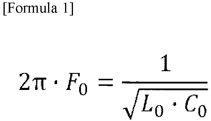
- The
drive signal generator 13 generates the alternating voltage applied to thevibrator device 10. Theresistance 14 is connected to thevibrator device 10 in order to measure the electric current that flows through thevibrator device 10. Theresistance 14 outputs the voltage proportional to the vibration velocity of thevibrators - The
amplitude detector 15 detects the amplitude of the vibration velocity detected by theresistance 14. Thecomparator 16 compares a vibration amplitude command from a vibration amplitude command unit (not shown) with the output from theamplitude detector 15, and outputs a comparison result to thedrive signal controller 17. Thedrive signal controller 17 controls thedrive signal generator 13 on the basis of the comparison result which the comparingunit 16 outputted. - The
drive signal controller 17 outputs a frequency command or an amplitude command to thedrive signal generator 13. The electric current that flows through thevibrator device 10 is approximately proportional to the vibration velocity of thevibrators inductors resistance 14 detects the electric current that flows through thevibrator device 10 and thedrive signal controller 17 controls the alternating signal, the amplitudes of thevibrators - Although an inductor is connected in parallel to each vibrator in the example of
FIG. 7 , a parallel circuit consisting of an inductor and a capacitor may be connected in parallel to each vibrator. A plurality of inductors that are connected in series or parallel may be connected in parallel to each vibrator in order to enable frequency matching at high accuracy. However, if a plurality of large-size inductors are used, the whole size of thevibrator device 10 will be enlarged. To avoid this, a capacitor may be added in parallel to the damping capacitance C0 instead of adjusting an inductor so as to adjust the value of the damping capacitance C0. This reduces enlargement of thevibrator device 10. - Next, failure of the
vibrator device 10 in this embodiment will be described. Since theinductors vibrator device 10 is able to continue to drive a contact member (for example, the cylindrical shaft 4), even if failure, such as a short circuit or disconnection, occurs in thevibrators vibrators FIG. 7 short-circuits electrically, the alternating voltage is continuously applied to the other vibrators. Since the short-circuited vibrator stops vibration, the loads to the other vibrators become heavy for that. Since the number of the available vibrators decreases, a thrust lower if the applied voltage does not change. In the meantime, when the number of available vibrators decreases, feedback control that increases the voltage applied to the available vibrators so as to maintain the thrust starts automatically. Thereby, the drive control of thevibrator device 10 is continuable. - Next, a case where disconnection occurs in a connection with a vibrator will be described. The
inductors - In the meantime, when disconnection occurs between the piezoelectric member joined to the vibrator and the wiring, a high impedance state by the parallel resonant circuit of the damping capacitance C0 and the inductor causes a state where the damping capacitance C0 disappears. This lowers the impedance and causes a state that is similar to the state where a vibrator short-circuits in greater or lesser degrees. Accordingly, since the voltage applied to the available vibrators increases, exciting force increases automatically as well as the case where a vibrator short-circuits. Thereby, the drive control of the
vibrator device 10 is continuable. - When the short circuit or disconnection occurs in the
vibrator device 10 as mentioned above, the electric current that flows through thevibrator device 10 increases as compared with the case where neither short circuit nor disconnection occurs. Theresistance 14 is measuring the electric current that flows through thevibrator device 10. When the increase in the electric current that flows through theresistance 14 is detected, occurrence of failure such as short circuit and disconnection is detected. For example, when an amount of increase of the electric current that flows through theresistance 14 is more than a predetermined amount, theamplitude detector 15 detects that failure occurs in thevibrator device 10. - Next, a drive circuit for a vibration actuator to which an amplifier circuit is added will be described.
FIG. 8 is a view showing an example of a drive circuit for a vibration actuator that is configured by adding atransformer 18 to the circuit ofFIG. 7 . Thetransformer 18 as an amplifier circuit is a boosting transformer and is connected to the output side of thedrive signal generator 13. Acapacitor 19 for frequency matching is connected in parallel to a secondary side of thetransformer 18. A relation between a value Lt of inductor at the secondary side of thetransformer 18, an electrostatic capacity Ct of thecapacitor 19, and the matching frequency Ft that is decided by the driving frequency range of thevibrator device 10 is represented by the followingformula 2.
- When the frequency matching at the secondary side of the
transformer 18 is appropriately taken so as to satisfy the above-mentionedformula 2, the electric current that is approximately proportional to a secondary-side current flows at a primary side of thetransformer 18 within the driving frequency range mentioned above. Accordingly, the same operation asFIG. 7 is achievable by detecting the primary-side current of thetransformer 18 by theresistance 14 like the drive circuit ofFIG. 7 . -
FIG. 9 is a view showing another configuration example of thevibrator device 10 ofFIG. 8 . As shown inFIG. 9 , thetransformer 18 and thecapacitor 19 are built in thevibrator device 10. Since thetransformer 18 is built in the input side of thevibrator device 10, thevibrator device 10 can be driven at relatively low voltage. -
FIG. 10A and FIG. 10B are views showing examples of the vibration actuators concerning the first embodiment.FIG. 10A is a view showing an example of the vibration actuator that is constituted by connecting threevibrator devices FIG. 10B is a view showing an example of the vibration actuator that is constituted by connecting the threevibrator devices - The number of the
vibrator devices 10 connected in series or in parallel is not limited to three. Since onevibrator device 10 has three vibrators as mentioned above, the vibration actuator inFIG. 10A employs nine vibrators. Nine vibrators connected in series may be built in one vibrator device. In the meantime, when the vibrators are divided into a plurality of vibrator devices, there is a merit that output torque is adjusted by adjusting the number of vibrator devices according to required output torque. Thevibrator devices vibrator device 10. Three vibrators connected in series are built in each of thevibrator devices - Hereinafter, an example of manufacturing of the
vibrator devices FIG. 10A and FIG. 10B will be described. Thevibrator devices - Accordingly, three vibrators of which the average of the resonance frequencies falls within the above-mentioned frequency range are built in one vibrator device. It is difficult to prepare many vibrators of which resonance frequencies are close. In the meantime, the method for preparing vibrators using the average of the resonance frequencies like this embodiment enables to prepare relatively large number of vibrators.
- Moreover, vibrators that constitute one vibrator device may be selected using dispersion of resonance frequencies instead of the average. That is, in this case, vibrators of which the dispersion of the resonance frequencies falls within a predetermined dispersion range are built in one vibrator device. When the dispersion is set to a large value to some extent, there is unevenness of the resonance frequencies of the selected vibrators, which stabilizes the characteristic of the vibrator device. As mentioned above, when a vibration actuator is constituted by combining a plurality of vibrator devices of the same class, a high-power and high-efficiency vibration actuator is manufactured stably.
- In the case in
FIG. 10A , the threevibrator devices - Accordingly, the configuration in which the
vibrator devices FIG. 10B . In this case, since the threevibrator devices vibrator devices - The
vibrator devices cylindrical shaft 4, the loads of three vibrators are equalized. Accordingly, there is little load fluctuation during rotation. This reduces the difference between the vibration velocities of the vibrator devices and achieves efficient drive. -
FIG. 11A, FIG. 11B, and FIG. 11C are views showing attachment phases of therespective vibrator devices cylindrical shaft 4. The three vibrator devices are attached so that the rotation phases are shifted every 40 degrees. Since thevibrator devices cylindrical shaft 4 by shifting the phases by the predetermined angle as shown inFIG. 11A, FIG. 11B, and FIG. 11C , rotation of thecylindrical shaft 4 with few torque fluctuation is achieved. The three vibrators are connected in series in each of thevibrator devices FIG. 11A, FIG. 11B, and FIG. 11C , the vibrators are arranged every 120 degrees. When the vibrator device has two vibrators, two vibrators are preferably arranged every 180 degrees. Moreover, when the vibrator device has four vibrators, four vibrators are preferably arranged every 90 degrees. -
FIG. 12 is a view showing a drive circuit for the three vibration actuators ofFIG. 10B . Each of thevibrator devices drive signal generator 13 outputs. That is, a relation between the matching frequency F0, the damping capacitance C0, and the value L0 of the inductor is represented by the above-mentionedformula 1. - The
drive signal generator 13 generates the alternating voltage applied to thevibrator devices resistance 14 is used to measure the total electric current that flows through thevibrator devices vibrator devices cylindrical shaft 4. Accordingly, the phase of inflow electric current does not deviate largely. - Accordingly, the
amplitude detector 15 outputs the voltage proportional to the sum of the amplitudes of electric currents that flow through thevibrator devices comparator 16 compares the sum of the amplitudes of electric currents with the vibration amplitude command from the command unit (not shown). Thedrive signal controller 17 controls the frequency or amplitude of the alternating voltage that thedrive signal generator 13 outputs on the basis of the comparison result. - Although the example that the plurality of vibrator devices drives the same contact member is described in this embodiment, the plurality of vibrator devices may respectively drive different contact members. In this case, although it is difficult to drive the contact members at the completely same speed, the circuit structure can be reduced because the plurality of contact members are simultaneously driven at the similar vibration velocities.
- Moreover, although the example in which the vibrators of the same configuration are applied to each vibrator device is described in this embodiment, the vibrators of different configurations may be applied to each vibrator device as long as the resonance frequencies of the vibrators fall within the predetermined range.
- Moreover,
FIG. 10A and FIG. 10B respectively show the vibration actuators in which the plurality ofvibrator devices vibrator devices cylindrical shaft 4 may differ according to the positions that thevibrator devices respective vibrator devices transformer 18 is provided inside each of thevibrator devices FIG. 9 is employed. Then, the ratio of the vibration velocities is adjusted by adjusting the winding ratios of thetransformers 18. That is, the vibration velocity of each of thevibrator devices transformers 18 according to the condition of the contact member. - Next, a second embodiment of the present invention will be described.
FIG. 13 is a view showing an example of a vibration actuator concerning the second embodiment. As shown inFIG. 13 , each of three shaft-output vibration actuators rotation shaft 33A using a bevel gear mechanism to rotate therotation shaft 33A. Abevel gear 22 is attached at a front end of anoutput shaft 21 of thevibration actuator 20. Abevel gear 29 is attached at a front end of anoutput shaft 28 of thevibration actuator 27. Abevel gear 32 is attached at a front end of anoutput shaft 31 of thevibration actuator 30. The bevel gears 22, 29, and 32 engage with alarger bevel gear 33 attached to therotation shaft 33A at angular intervals of 120 degrees. - The vibrators of the
respective vibration actuators bevel gear 33 connected indirectly is driven.FIG. 14 is a view showing one example of a configuration of thevibration actuator 20 concerning the second embodiment. Thevibration actuator 20 has arotor 23, ceramicelastic body 24,piezoelectric member 25, andfriction member 26. Theoutput shaft 21 is joined to the center of therotor 23. Theoutput shaft 21 androtor 23 are supported rotatably. The ceramicelastic body 24 is a non-conductive member that has a comb-like projection structure. Thepiezoelectric member 25 is adhered to the ceramicelastic body 24. Moreover, thefriction member 26 is adhered on the projection structure of the ceramicelastic body 24. The material of thefriction member 26 is selected so that a contact portion to therotor 23 slowly and stably wears out. -
FIG. 15 is a view showing an electrode structure of the circularpiezoelectric member 25.FIG. 15 shows a connection state betweenelectrodes piezoelectric member 25 on its front surface and the drive voltage lines of the phases A, B, NA, and NB -
FIG. 16 is a view showing a wiring structure of thepiezoelectric member 25. Electrodes of thepiezoelectric member 25 on its back surface are also distributed as well as theelectrodes FIG. 15 . A back electrode of the phase NA is opposite to theelectrode 34 of the phase A. A back electrode of the phase BA is opposite to theelectrode 35 of the phase B. As shown inFIG. 16 , aninductor 38 is connected in parallel between the phases A and NA and aninductor 39 is connected in parallel between the phases B and NB. The phase difference between the alternating voltages applied to the phases A and NA is equal to 180 degrees, and the phase difference between the alternating voltages applied to the phases B and NB is the same as it. -
FIG. 17 is a view showing a first example of a drive circuit for the vibration actuator concerning the second embodiment. In thevibration actuator 20, a plurality of vibration sections of which phases are different are formed by the alternating voltages that have the phase difference of 180 degrees and are input by the phases A and NA and the phases B and NB. The two vibration sections of which phases are different are indicated by two vibrators inFIG. 17 . Theinductor 38 is connected in parallel between the phases A and NA and theinductor 39 is connected in parallel between the phases B and NB. - The
vibration actuators vibration actuators FIG. 17 , the threevibration actuators vibration actuator 40 that has terminals A, NA, B, and NB as a whole. An area surrounded with a broken line indicates eachvibration actuator vibration actuator 40. - The
capacitor 19 for frequency matching and the secondary side winding of thetransformer 18 for amplification are connected in parallel between the terminals A and NA of thevibration actuator 40. Moreover, thecapacitor 42 for frequency matching and the secondary side winding of thetransformer 41 for amplification are connected in parallel between the terminals B and NB of thevibration actuator 40. Thedrive signal generator 43 generates an alternating voltage. H-bridge circuits (power amplification circuits, not shown) are respectively connected between the terminals A and NA and between the terminals B and NB of thedrive signal generator 43. - Waveforms of pulse drive signals that the H-bridge circuits output are shaped by series resonant circuits constituted by
inductors capacitors transformers drive signal generator 43. Then, the pulse drive signals after the waveform shaping are amplified by thetransformers vibration actuator 40. The series resonant circuits constituted by theinductors capacitors vibration actuator 40. This suppresses large fluctuation of the drive voltage amplitude of thevibration actuator 40 within the driving frequency range. -
Resistances drive signal generator 43. Theresistances vibration actuator 40. Theamplitude detector 15 detects the amplitude of the vibration velocities of the vibrators on the basis of the measurement values of theresistances comparator 16 compares the vibration amplitude command from the vibration amplitude command unit (not shown) with the detection results (amplitude velocities of the vibrators) of theamplitude detector 15. Thedrive signal controller 17 outputs at least one command among commands about the frequency, pulse width, and voltage amplitude to thedrive signal generator 43 according to the comparison result. - Generally, a vibration actuator has irregularity or fluctuation in a resonance frequency or an internal loss under the influence of manufacture irregularity of a friction member or pressure irregularity owing to plane accuracy of a vibrator. In addition, since there are variation depending on a rotation angle and variation with time resulting from progress of wear, it is difficult to make vibration characteristics of a plurality of vibration actuators uniform. As a countermeasure for this, an inductor is connected in parallel to each of the vibrators that are connected in series in this embodiment as mentioned above. This makes the amplitude characteristics of the vibrators uniform, allows to transmit the comparatively equal force to the
bevel gear 33, and enables the efficient drive with little wear of the gears. - Although the
vibration actuator 40 does not include thetransformers inductors capacitors FIG. 17 , some or all of these components may be included in thevibration actuator 40. Since thevibration actuator 40 includes the components that are subjected to the frequency matching in accordance with the inherent resonance frequency, adjustment at the time of using thevibration actuator 40 becomes unnecessary. This reduces variation in performance and improves convenience of the user who uses thevibration actuator 40. Moreover, either of theinductor 44 and thecapacitor 45 may be connected in series to the primary side of thetransformer 18. Similarly, either of theinductor 46 and thecapacitor 47 may be connected in series to the primary side of thetransformer 41. A capacitor is used to intercept direct current and an inductor has an effect to smooth a waveform. - Moreover, in this embodiment, the entire configuration including the three
vibration actuators bevel gear 33 is described as the onevibration actuator 40. Assuming that thevibration actuator 40 is one vibrator device, a configuration in which the vibrator devices are connected in series or in parallel can be also employed. Thereby, a high-output vibration actuator is constituted. In this case, it is preferable that the average of the resonance frequencies of the vibrators in each of the vibration actuators, which constitute the vibrator devices, be approximately equal to the average of the resonance frequencies of the three vibrators in thevibration actuator 40. - Moreover, the above-mentioned vibrator devices may be mechanically combined by connecting a plurality of complex vibration actuators as shown in
FIG. 13 in a state where a plurality of gears equivalent to thebevel gear 33 are fixed to thesame shaft 33A. Alternatively, the vibrator devices may be combined through other gears. -
FIG. 18 is a view showing a second example of a drive circuit for the vibration actuator concerning the second embodiment. In the drive circuit for the vibration actuator of the second example, twovibrator devices vibrator device 104 has thevibration actuators transformers vibrator device 107 hasvibration actuators transformers FIG. 18 , the ratio of the rotational speeds of the vibrator devices is adjustable by changing the winding ratios of the transformers of the vibrator devices. - Moreover, the three
vibration actuators - For example, a doll is attached in place of the
bevel gear 22 of the vibration actuator inFIG. 14 . When three vibration actuators to which different dolls are respectively attached are electrically connected in series, the three dolls are rotated at the almost same speed. Moreover, the drive circuit for the vibration actuator inFIG. 18 is able to change the rotation speeds of the dolls for every vibrator device by adjusting the winding ratio of each transformer. Moreover, when the gear ratio of the engaged gears is adjusted while adjusting the winding ratio of each transformer, the adjustment depending on required torque is also available. - Next, a third embodiment will be described.
FIG. 19A through FIG. 19D are views showing a configuration and vibration modes of a vibrator concerning the third embodiment. As shown inFIG. 19A , avibrator 49 has a plate shape and is manufactured from non-conductive material. Two projections that contact a contact member are provided in the surface of thevibrator 49. Apiezoelectric member 50 constitutes a part of thevibrator 49 and vibrates thevibrator 49.FIG. 19B showselectrodes piezoelectric member 50. Theelectrodes electrode 53 and theelectrode 54. Two similar electrodes are also provided on a back surface of thepiezoelectric member 50 and are configured so as to enable energization from the front surface through via holes (not shown) provided in parts of theelectrodes -
FIG. 19C shows a vibration form in a vibration mode excited when alternating voltages of the same phase are applied to theelectrodes FIG. 19D shows a vibration form of the vibration mode excited when alternating voltages of opposite phases are applied to theelectrodes electrodes 53 and theelectrode 54 is 0 degrees, the vibration mode ofFIG. 19C is excited. When the phase difference between the alternating voltages applied to theelectrodes 53 and theelectrode 54 is 180 degrees, the vibration mode ofFIG. 19D is excited. - Moreover, when the phase difference of alternating voltages is an angle between 0 degrees and 180 degrees, both the vibration modes are excited simultaneously. The phase difference of alternating voltages is an angle between 0 degrees and 120 degrees in many cases. Then, a contact member that presses the projections provided in the
vibrator 49 moves. When the contact member is a rectangular parallelepiped, the contact member that presses the projections provided in thevibrator 49 moves in a rectangular longitudinal direction. -
FIG. 20A and FIG. 20B are views showing a first example of a linear-motion vibration actuator of the third embodiment.FIG. 20A is a figure viewed from a direction that intersects perpendicularly with a moving direction of acontact member 52. Projections of the twovibrators contact member 52 will move in a direction of an arrow inFIG. 20A in a state where the projections put thecontact member 52 therebetween from the vertical direction.FIG. 20B is a figure viewed from the moving direction of thecontact member 52. Thevibrators contact member 52. -
FIG. 21 is a view showing a first example of the drive circuit for the vibration actuator concerning the third embodiment. As shown inFIG. 21 , the piezoelectric members of thevibrator 49 and the piezoelectric members of thevibrator 51 are connected in series for each phase, and the inductors are respectively connected in parallel to thevibrators vibrators drive signal generator 43 through the series resonant circuit that consists of theinductors capacitors - The series resonant circuit may consist of inductors only or capacitors only. The
drive signal generator 43 outputs pulse signals of four phases that differ every 90 degrees. Athrust detector 55 detects thrust to thecontact member 52 and outputs the detected thrust to acomparator 56. Thecomparator 56 compares the detected thrust with a thrust command from an command unit (not shown) and outputs a comparison result. A vibrationamplitude command unit 57 controls the vibration amplitudes of thevibrators comparator 56 outputs. - Moreover, the
resistance vibrators drive signal generator 43. Theamplitude detector 15 detects the vibration amplitudes from the electric currents that theresistances comparator 16 compares the detected vibration amplitudes and the vibration amplitude command from the vibrationamplitude command unit 57. Thedrive signal controller 17 controls at least one of the frequency, pulse width, and voltage amplitude of the pulse signals that thedrive signal generator 43 generates according to the comparison result. - For example, when the thrust of the
vibrators drive signal generator 43 outputs approaches the resonance frequency of thevibrators vibrators vibrators contact member 52 can be controlled when a configuration in which thethrust detection part 55 is replaced with a speed detector that detects the speed of thecontact member 52 and thecomparator 56 compares the detected speed with a speed command from a command unit (not shown) is employed. - Moreover, although the vibrator device is constituted by the upper and lower two
vibrators contact member 52 therebetween in the example ofFIG. 20A and FIG. 20B , thecontact member 52 may be a prism having a square section and thevibrators FIG. 22A and FIG. 22B are views showing a second example of a linear-motion vibration actuator concerning the third embodiment. As shown inFIG. 22A and FIG. 22B , fourvibrators contact member 64 that is a prism having a square section at angular intervals of 90 degrees on the circumference. Thevibrators FIG. 22A and FIG. 22B are connected in series for each phase of the alternating voltage that is applied to two electrodes (not shown) of a piezoelectric member of each vibrator. And the inductors are respectively connected in parallel to the vibrators. Thecontact member 64 may be a cylindrical shape having a circular section. - Although one vibrator device is constituted by connecting the four vibrators in series in the example of
FIG. 22A and FIG. 22B , a configuration in which two vibrator devices each of which is constituted by two vibrators that are opposite to each other are connected in series or in parallel may be employed. Moreover, a configuration in which a plurality of vibrator devices each of which is constituted by four vibrators are arranged along the moving direction of thecontact member 64 and are connected in parallel or in series may be employed. - Moreover, a configuration in which a plurality of vibrators in which projections are provided on the same plane are equally arranged along a circumferential direction of a ring-shaped contact member or a circular contact member may be employed.
FIG. 23 is a view showing an example of a rotary-motion vibration actuator concerning the third embodiment. As shown inFIG. 23 , threevibrators circular contact member 61. Thevibrators vibrators FIG. 23 , the plurality of vibrators may respectively drive different contact members. Moreover, when the plurality of vibrators are divided into a plurality of vibrator devices, the respective vibrator devices may drive different contact members. - Next, a fourth embodiment will be described.
FIG. 24 is a view showing a first example of a vibration actuator concerning the fourth embodiment. As shown inFIG. 24 , twovibrators vibrators vibrators contact member 69 in a Y-axis direction. Thevibrators vibrators - The
vibrators contact member 69 in an X-axis direction. Thevibrators vibrators -
FIG. 25 is a view showing a first example of a drive circuit for the vibration actuator concerning the fourth embodiment. Thevibrators vibrators -
FIG. 26 is a graph showing electric current amplitude characteristics of the vibrator devices in the fourth embodiment. A solid line shows the vibration characteristic of the X-axis vibrator device, and a broken line shows the vibration characteristic of the Y-axis vibrator device. Driving frequency ranges are set at the higher sides of the respective maximum-amplitude frequencies. The frequency Fx for the X-axis and the frequency Fy for the Y-axis are set within the respective driving frequency ranges. - The
drive signal generator 70 inFIG. 25 generates two-phase alternating voltages in the respective frequency ranges by compositing the alternating voltages in the two frequency ranges including the frequency Fx for the X-axis and the frequency Fy for the Y-axis, respectively. Anamplitude detector 71 detects the vibration amplitudes in the frequency range for theX-axis and the frequency range for the Y-axis on the basis of the sum signal of the two-phase electric currents that flow according to the vibration velocities of the vibrators that theresistance 14 for current detection measures, and outputs the detection results.Comparators amplitude detector 71 outputs. Drivesignal controllers comparators - Moreover, the command unit monitors position signals output from a two-dimensional position detector (not shown) that detects a two-dimensional position of the
contact member 69. And the command unit compares the position signals with target positions in the respective axes. Then, the command unit switches the phases of the alternating voltages applied to the X-axis vibrator device and Y-axis vibrator device to 90 degrees or -90 degrees according to signs (+/-) of the comparison results and sets up a vibration amplitude command for the X-axis and a vibration amplitude command for the Y-axis according to the absolute values of the comparison results. As a method of separating the signals in the two frequency ranges, there are a method of separating the signals with a filter, a method of finding frequencies and amplitudes by the FFT computation, and a method of performing synchronous detection of the synchronizing signal that thedrive signal generator 70 generates. - Moreover, when the respective vibration velocities of the X-axis vibrator device and Y-axis vibrator device are detected from the sum signal of the electric currents, an error occurs in measurement of the amplitudes if the frequencies are merely separated. In view of this problem, an offset value for an amplitude for every frequency obtained beforehand is stored in the
amplitude detector 71. This enables detection of a vibration velocity at high accuracy by performing a correction calculation based on the offset value to the obtained information about the amplitude and frequency. -
FIG. 27 is a view showing a second example of a drive circuit for the vibration actuator concerning the fourth embodiment. The vibrator devices of which the driving frequency ranges differ are individually connected to thedrive signal generator 70 through the transformers, respectively. A series circuit that consists of an inductor and a capacitor that are subjected to frequency matching at a predetermined frequency within a driving frequency range decided for each vibrator device is inserted between each transformer and thedrive signal generator 70. -
FIG. 28 is a view showing a second example of the vibration actuator concerning the fourth embodiment. A plurality ofvibrator devices FIG. 28 have a plurality of vibrators connected in series and inductors connected in parallel to the respective vibrators. Thevibrator devices vibrator devices - Each of the
vibrator devices FIG. 20A, FIG. 20B ,FIG. 22A, and FIG. 22B . And awire bundle 79 is combined with the contact member. Thewire bundle 79 is engaged with a tube-shapedbending driver 80 that imitates a finger. The bendingdriver 80 is constituted so as to bend and stretch a plurality of pseudo joints by pulling and pressing wires of thewire bundle 79. One wire of thewire bundle 79 corresponds to each of thevibrator devices - The bending
driver 80 can be driven by linearly moving the contact members included in thevibrator devices - While the present invention has been described with reference to exemplary embodiments, it is to be understood that the invention is not limited to the disclosed exemplary embodiments. The scope of the following claims is to be accorded the broadest interpretation so as to encompass all such modifications and equivalent structures and functions.
- A vibration actuator that is capable of reducing difference of vibration velocities when a contact member is driven using a plurality of vibrators. The vibration actuator includes a vibrator device and a contact member that moves relative to the vibrator device. The vibrator device includes a plurality of vibrators that are connected in series, and a plurality of inductors that are connected in parallel to the respective vibrators.
Claims (18)
- A vibration actuator comprising:a vibrator device (10); anda contact member (4) that moves relative to the vibrator device (10),wherein the vibrator device (10) comprises:a plurality of vibrators (1, 2, 3) that are connected in series, anda plurality of inductors (5, 6, 7) that are connected in parallel to the respective vibrators (1, 2, 3).
- The vibration actuator according to claim 1, wherein a capacitor is connected in parallel to each of the plurality of inductors.
- The vibration actuator according to claim 1, wherein the plurality of vibrators (1, 2, 3) are arranged around the contact member (4) at approximately equal intervals and pressed the contact member (4).
- The vibration actuator according to claim 1, wherein values of the inductors (5, 6, 7) are matched at a frequency within a predetermined range from a resonance frequency of the vibrator device (10).
- The vibration actuator according to claim 1, wherein the inductors (5, 6, 7) that are respectively connected in parallel to the plurality of vibrators (1, 2, 3) are connected in series.
- The vibration actuator according to claim 1, further comprising at least one other vibrator device (11, 12), and
wherein the vibrator devices (10, 11, 12) are connected in parallel and contact the contact member (4). - The vibration actuator according to claim 5, wherein an average of the resonance frequencies of the plurality of vibrators (1, 2, 3) falls within a predetermined frequency range.
- The vibration actuator according to claim 5, wherein dispersion of the resonance frequencies of the plurality of vibrators (1, 2, 3) falls within a predetermined dispersion range.
- The vibration actuator according to claim 6, wherein driving frequency ranges of the vibrator devices do not overlap.
- The vibration actuator according to claim 1, wherein the vibrator device has a plurality of vibrators each of which has a plurality of vibration sections that are different in a phase of input alternating voltage, and
wherein the plurality of vibration sections of the plurality of vibrators are connected in series for every phase and the inductors are connected in parallel to the plurality of vibration sections, respectively. - The vibration actuator according to claim 1, wherein the vibrator device is provided with a transformer (18) at an input side.
- The vibration actuator according to claim 1, further comprising at least one other vibrator device,
wherein the vibrator devices that drive the same contact member are respectively provided with transformers (18, 41) at input sides, and
wherein winding ratios of the transformers (18, 41) are different. - The vibration actuator according to claim 1, further comprising a wire, and
wherein the wire is movable by the vibrator device and the contact member that move relatively and mutually. - A driving device for a vibration actuator equipped with a vibrator device (10) and a contact member (4) that move relatively and mutually, the driving device comprising:a drive signal generator (13) that generates an alternating voltage applied to the vibrator device (10);an amplitude detector (15) that detects amplitude of an electric current flowing to the vibrator device (10); anda drive signal controller (17) that controls the alternating voltage that the drive signal generator (13) generates according to the amplitude of the electric current,wherein the vibrator device (10) comprisesa plurality of vibrators (1, 2, 3) that are connected in series, anda plurality of inductors (5, 6, 7) that are connected in parallel to the respective vibrators.
- The driving device for the vibration actuator according to claim 14, wherein the amplitude detector (15) detects that failure occurs in the vibrator device (10) in a case where an amount of increase of the electric current is more than a predetermined amount.
- The driving device for the vibration actuator according to claim 14, wherein the drive signal generator (70) generates an alternating voltage that alternating voltages of different frequency ranges are composited,
wherein the amplitude detector (71) detects the amplitude of the electric current about each of the different frequency ranges, and
wherein the drive signal controller (17, 73) controls the alternating voltage that the drive signal generator (70) generates about each of the different frequency ranges. - The driving device for the vibration actuator according to claim 14, wherein a transformer (18) is inserted between the drive signal generator (13) and the vibrator device (10).
- The driving device for the vibration actuator according to claim 14, wherein the vibration actuator is provided with at least one other vibrator device,
wherein transformers (18, 41) are inserted between the drive signal generator (40) and the respective vibrator devices, and
wherein winding ratios of the transformers (18, 41) are different.
Applications Claiming Priority (1)
| Application Number | Priority Date | Filing Date | Title |
|---|---|---|---|
| JP2019058725A JP7297489B2 (en) | 2019-03-26 | 2019-03-26 | Vibration type actuator and driving device for vibration type actuator |
Publications (2)
| Publication Number | Publication Date |
|---|---|
| EP3716466A1 true EP3716466A1 (en) | 2020-09-30 |
| EP3716466B1 EP3716466B1 (en) | 2024-09-04 |
Family
ID=70056808
Family Applications (1)
| Application Number | Title | Priority Date | Filing Date |
|---|---|---|---|
| EP20165512.3A Active EP3716466B1 (en) | 2019-03-26 | 2020-03-25 | Vibration actuator with series-connected vibrators and driving device including the same |
Country Status (4)
| Country | Link |
|---|---|
| US (1) | US11728750B2 (en) |
| EP (1) | EP3716466B1 (en) |
| JP (1) | JP7297489B2 (en) |
| CN (1) | CN111756271B (en) |
Cited By (1)
| Publication number | Priority date | Publication date | Assignee | Title |
|---|---|---|---|---|
| CN116300415A (en) * | 2022-09-07 | 2023-06-23 | 瑞声开泰声学科技(上海)有限公司 | A method, device and electronic device for controlling output consistency of multiple vibrators |
Families Citing this family (5)
| Publication number | Priority date | Publication date | Assignee | Title |
|---|---|---|---|---|
| EP4236058A4 (en) * | 2020-10-22 | 2024-12-18 | Canon Kabushiki Kaisha | VIBRATION DRIVE DEVICE AND METHOD FOR DRIVING THE VIBRATION DRIVE DEVICE |
| JP7520686B2 (en) * | 2020-10-22 | 2024-07-23 | キヤノン株式会社 | Vibration type driving device and driving method for a vibration type driving device |
| JP2022069736A (en) * | 2020-10-26 | 2022-05-12 | キヤノン株式会社 | Vibration type drive device |
| JP7520687B2 (en) * | 2020-10-22 | 2024-07-23 | キヤノン株式会社 | Vibration type driving device and driving method |
| JP2024061174A (en) * | 2022-10-21 | 2024-05-07 | 国立研究開発法人産業技術総合研究所 | Vibration device, vibration unit and vibration apparatus |
Citations (6)
| Publication number | Priority date | Publication date | Assignee | Title |
|---|---|---|---|---|
| US20080278033A1 (en) * | 2007-05-07 | 2008-11-13 | Yusuke Adachi | Piezoelectric element, vibratory actuator and drive unit |
| JP2008278712A (en) | 2007-05-07 | 2008-11-13 | Matsushita Electric Ind Co Ltd | Drive device |
| WO2015174039A1 (en) * | 2014-05-14 | 2015-11-19 | Canon Kabushiki Kaisha | Vibration type driving apparatus, interchangeable lens and imaging apparatus including vibration type driving apparatus, and method for adjusting vibration type driving apparatus |
| EP3051599A1 (en) * | 2015-02-02 | 2016-08-03 | Seiko Epson Corporation | Piezoelectric element drive circuit and robot |
| JP2017104014A (en) | 2017-03-13 | 2017-06-08 | キヤノン株式会社 | Drive device and drive control method for vibration actuator |
| US20180090668A1 (en) * | 2016-09-26 | 2018-03-29 | Seiko Epson Corporation | Driving device, piezoelectric motor, electronic component conveyance apparatus, and robot |
Family Cites Families (32)
| Publication number | Priority date | Publication date | Assignee | Title |
|---|---|---|---|---|
| FR1390283A (en) * | 1964-01-03 | 1965-02-26 | Siderurgie Fse Inst Rech | Improvements to devices emitting and receiving ultra-sound energy |
| JPS63302774A (en) * | 1987-05-29 | 1988-12-09 | Olympus Optical Co Ltd | Driving circuit for ultrasonic wave motor |
| US5285134A (en) | 1990-03-09 | 1994-02-08 | Canon Kabushiki Kaisha | Control device for vibration type motor |
| JPH0488889A (en) * | 1990-07-27 | 1992-03-23 | Brother Ind Ltd | Driver for ultrasonic motor |
| JP2001078472A (en) | 1999-09-03 | 2001-03-23 | Sony Corp | Ultrasonic motor driving apparatus and ultrasonic motor driving method |
| JP2002281770A (en) | 2001-03-21 | 2002-09-27 | Minolta Co Ltd | Piezo actuator |
| JP3540311B2 (en) * | 2002-05-31 | 2004-07-07 | 松下電器産業株式会社 | Motor drive control device |
| JP3999715B2 (en) * | 2003-08-28 | 2007-10-31 | オリンパス株式会社 | Ultrasonic treatment device |
| JP2006333682A (en) | 2005-05-30 | 2006-12-07 | Olympus Corp | Method for setting drive signal frequency of ultrasonic motor and driving device for ultrasonic motor |
| JP4721431B2 (en) * | 2006-02-24 | 2011-07-13 | キヤノン株式会社 | Power supply, image forming apparatus and IC |
| JP5151310B2 (en) | 2007-08-15 | 2013-02-27 | ソニー株式会社 | Piezoelectric element drive circuit and pump device |
| US7532084B2 (en) * | 2007-08-31 | 2009-05-12 | Murata Manufacturing Co., Ltd | Nonreciprocal circuit element |
| JP2010041346A (en) * | 2008-08-05 | 2010-02-18 | Nippon Dempa Kogyo Co Ltd | Quartz oscillation circuit of suboscillation suppressing type |
| WO2010041533A1 (en) | 2008-10-07 | 2010-04-15 | コニカミノルタオプト株式会社 | Ultrasonic motor and piezoelectric oscillator |
| JP5436164B2 (en) | 2009-11-20 | 2014-03-05 | キヤノン株式会社 | Drive circuit for vibration actuator |
| KR101055463B1 (en) * | 2010-03-19 | 2011-08-08 | 삼성전기주식회사 | Linear oscillator |
| JP5506552B2 (en) * | 2010-06-07 | 2014-05-28 | キヤノン株式会社 | Control device for vibration actuator and control method for vibration actuator |
| JP5645489B2 (en) * | 2010-06-09 | 2014-12-24 | キヤノン株式会社 | Control device and adjustment method of vibration actuator using a plurality of vibrators, vibration actuator, lens unit using the same, and optical apparatus |
| CN104871328A (en) | 2012-12-21 | 2015-08-26 | 佳能株式会社 | Vibration wave driving device, image pickup device, optical apparatus, liquid discharge device, and electronic apparatus |
| JP5693699B2 (en) * | 2013-12-11 | 2015-04-01 | キヤノン株式会社 | Vibration body drive circuit |
| JP6415301B2 (en) * | 2013-12-26 | 2018-10-31 | キヤノン株式会社 | Vibration body drive circuit, vibration actuator, imaging device, image generation device, and dust removal device |
| CN104124879B (en) * | 2014-07-01 | 2017-02-15 | 南京航空航天大学 | Vibration energy recovery interface circuit and control method thereof |
| JP6543896B2 (en) * | 2014-08-13 | 2019-07-17 | セイコーエプソン株式会社 | Piezoelectric drive device, robot, and method of driving them |
| DE102014112676A1 (en) * | 2014-09-03 | 2016-03-03 | Epcos Ag | Filter with improved linearity |
| JP6503764B2 (en) | 2015-02-02 | 2019-04-24 | セイコーエプソン株式会社 | Piezoelectric element drive circuit and robot |
| JP6529279B2 (en) | 2015-02-24 | 2019-06-12 | キヤノン株式会社 | Vibration type drive device, lens barrel and imaging device |
| JP6602044B2 (en) * | 2015-05-08 | 2019-11-06 | キヤノン株式会社 | Vibration type driving device, control device, and medical system |
| JP2017022942A (en) * | 2015-07-14 | 2017-01-26 | キヤノン株式会社 | Vibrating actuator control device and control method thereof, drive device, imaging device, and automatic stage |
| JP6639148B2 (en) * | 2015-08-18 | 2020-02-05 | キヤノン株式会社 | Drive circuit of vibration type actuator, vibration device, replacement lens, imaging device, and automatic stage |
| JP2017175696A (en) * | 2016-03-22 | 2017-09-28 | セイコーエプソン株式会社 | Control circuit of piezoelectric drive device, piezoelectric drive device, ultrasonic motor, robot, hand, and pump |
| JP6651937B2 (en) | 2016-03-28 | 2020-02-19 | セイコーエプソン株式会社 | Piezo actuators, piezo motors, robots, hands and pumps |
| US10881399B2 (en) * | 2017-06-20 | 2021-01-05 | Ethicon Llc | Techniques for adaptive control of motor velocity of a surgical stapling and cutting instrument |
-
2019
- 2019-03-26 JP JP2019058725A patent/JP7297489B2/en active Active
-
2020
- 2020-03-20 US US16/825,201 patent/US11728750B2/en active Active
- 2020-03-23 CN CN202010205547.0A patent/CN111756271B/en active Active
- 2020-03-25 EP EP20165512.3A patent/EP3716466B1/en active Active
Patent Citations (6)
| Publication number | Priority date | Publication date | Assignee | Title |
|---|---|---|---|---|
| US20080278033A1 (en) * | 2007-05-07 | 2008-11-13 | Yusuke Adachi | Piezoelectric element, vibratory actuator and drive unit |
| JP2008278712A (en) | 2007-05-07 | 2008-11-13 | Matsushita Electric Ind Co Ltd | Drive device |
| WO2015174039A1 (en) * | 2014-05-14 | 2015-11-19 | Canon Kabushiki Kaisha | Vibration type driving apparatus, interchangeable lens and imaging apparatus including vibration type driving apparatus, and method for adjusting vibration type driving apparatus |
| EP3051599A1 (en) * | 2015-02-02 | 2016-08-03 | Seiko Epson Corporation | Piezoelectric element drive circuit and robot |
| US20180090668A1 (en) * | 2016-09-26 | 2018-03-29 | Seiko Epson Corporation | Driving device, piezoelectric motor, electronic component conveyance apparatus, and robot |
| JP2017104014A (en) | 2017-03-13 | 2017-06-08 | キヤノン株式会社 | Drive device and drive control method for vibration actuator |
Non-Patent Citations (1)
| Title |
|---|
| SATONOBU J ET AL: "Electrical Series Connection Drive for Several Hybrid-Transducer Ultrasonic Motors", ELECTRONICS AND COMMUNICATIONS IN JAPAN, PART 3, vol. 81, no. 12, December 1998 (1998-12-01), pages 11 - 22, XP000869390, ISSN: 1042-0967, DOI: 10.1002/(SICI)1520-6440(199812)81:12<11::AID-ECJC2>3.0.CO;2-U * |
Cited By (1)
| Publication number | Priority date | Publication date | Assignee | Title |
|---|---|---|---|---|
| CN116300415A (en) * | 2022-09-07 | 2023-06-23 | 瑞声开泰声学科技(上海)有限公司 | A method, device and electronic device for controlling output consistency of multiple vibrators |
Also Published As
| Publication number | Publication date |
|---|---|
| JP2020162260A (en) | 2020-10-01 |
| CN111756271A (en) | 2020-10-09 |
| JP7297489B2 (en) | 2023-06-26 |
| US11728750B2 (en) | 2023-08-15 |
| EP3716466B1 (en) | 2024-09-04 |
| US20200313573A1 (en) | 2020-10-01 |
| CN111756271B (en) | 2024-08-23 |
Similar Documents
| Publication | Publication Date | Title |
|---|---|---|
| EP3716466B1 (en) | Vibration actuator with series-connected vibrators and driving device including the same | |
| US5656881A (en) | Vibration wave driven motor | |
| US10031316B2 (en) | Vibration type driving apparatus, interchangeable lens and imaging apparatus including vibration type driving apparatus, and method for adjusting vibration type driving apparatus | |
| JP3402816B2 (en) | Ultrasonic motor drive circuit | |
| US7759840B2 (en) | Ultrasonic motor and vibration detection method for ultrasonic motor | |
| US10693394B2 (en) | Driving apparatus of vibration-type actuator method of controlling driving vibration-type actuator and image pickup apparatus | |
| CN112886860B (en) | A Rotary Ultrasonic Motor Based on Three-phase Piezoelectric Stacking Drive Mode | |
| JP2014018027A (en) | Vibration type actuator, imaging apparatus, and stage | |
| EP3731401B1 (en) | Vibration actuator and driving device for vibration actuator | |
| JP2009284635A (en) | Drive system | |
| US7321182B2 (en) | Oscillatory-wave actuator and method for driving oscillatory-wave actuator | |
| JP2008236820A (en) | Driving device | |
| JP6497964B2 (en) | Vibrating actuator, lens barrel, camera, and control method | |
| JP4125041B2 (en) | Drive device for laminated vibration actuator | |
| JP5315434B2 (en) | Drive device | |
| JP7328056B2 (en) | Vibration Drives, Vibration Actuators, and Electronics | |
| JP2005102368A (en) | Drive device | |
| JP2990729B2 (en) | Ultrasonic motor drive | |
| JP2980399B2 (en) | Vibration type driving device and device using vibration type driving device as driving source | |
| JP2013247800A (en) | Drive device for vibration wave motor, lens barrel, and camera | |
| JP2019080490A (en) | Vibration type actuator, lens barrel, camera, and control method | |
| JPH04331483A (en) | Ultrasonic motor | |
| JPH04121077A (en) | ultrasonic motor |
Legal Events
| Date | Code | Title | Description |
|---|---|---|---|
| PUAI | Public reference made under article 153(3) epc to a published international application that has entered the european phase |
Free format text: ORIGINAL CODE: 0009012 |
|
| STAA | Information on the status of an ep patent application or granted ep patent |
Free format text: STATUS: THE APPLICATION HAS BEEN PUBLISHED |
|
| AK | Designated contracting states |
Kind code of ref document: A1 Designated state(s): AL AT BE BG CH CY CZ DE DK EE ES FI FR GB GR HR HU IE IS IT LI LT LU LV MC MK MT NL NO PL PT RO RS SE SI SK SM TR |
|
| AX | Request for extension of the european patent |
Extension state: BA ME |
|
| STAA | Information on the status of an ep patent application or granted ep patent |
Free format text: STATUS: REQUEST FOR EXAMINATION WAS MADE |
|
| 17P | Request for examination filed |
Effective date: 20210330 |
|
| RBV | Designated contracting states (corrected) |
Designated state(s): AL AT BE BG CH CY CZ DE DK EE ES FI FR GB GR HR HU IE IS IT LI LT LU LV MC MK MT NL NO PL PT RO RS SE SI SK SM TR |
|
| STAA | Information on the status of an ep patent application or granted ep patent |
Free format text: STATUS: EXAMINATION IS IN PROGRESS |
|
| 17Q | First examination report despatched |
Effective date: 20210830 |
|
| GRAP | Despatch of communication of intention to grant a patent |
Free format text: ORIGINAL CODE: EPIDOSNIGR1 |
|
| STAA | Information on the status of an ep patent application or granted ep patent |
Free format text: STATUS: GRANT OF PATENT IS INTENDED |
|
| INTG | Intention to grant announced |
Effective date: 20240404 |
|
| RIN1 | Information on inventor provided before grant (corrected) |
Inventor name: KATAOKA, KENICHI |
|
| GRAS | Grant fee paid |
Free format text: ORIGINAL CODE: EPIDOSNIGR3 |
|
| GRAA | (expected) grant |
Free format text: ORIGINAL CODE: 0009210 |
|
| STAA | Information on the status of an ep patent application or granted ep patent |
Free format text: STATUS: THE PATENT HAS BEEN GRANTED |
|
| AK | Designated contracting states |
Kind code of ref document: B1 Designated state(s): AL AT BE BG CH CY CZ DE DK EE ES FI FR GB GR HR HU IE IS IT LI LT LU LV MC MK MT NL NO PL PT RO RS SE SI SK SM TR |
|
| REG | Reference to a national code |
Ref country code: GB Ref legal event code: FG4D |
|
| REG | Reference to a national code |
Ref country code: CH Ref legal event code: EP |
|
| REG | Reference to a national code |
Ref country code: IE Ref legal event code: FG4D |
|
| REG | Reference to a national code |
Ref country code: DE Ref legal event code: R096 Ref document number: 602020036909 Country of ref document: DE |
|
| REG | Reference to a national code |
Ref country code: LT Ref legal event code: MG9D |
|
| REG | Reference to a national code |
Ref country code: NL Ref legal event code: MP Effective date: 20240904 |
|
| PG25 | Lapsed in a contracting state [announced via postgrant information from national office to epo] |
Ref country code: NO Free format text: LAPSE BECAUSE OF FAILURE TO SUBMIT A TRANSLATION OF THE DESCRIPTION OR TO PAY THE FEE WITHIN THE PRESCRIBED TIME-LIMIT Effective date: 20241204 |
|
| PG25 | Lapsed in a contracting state [announced via postgrant information from national office to epo] |
Ref country code: PL Free format text: LAPSE BECAUSE OF FAILURE TO SUBMIT A TRANSLATION OF THE DESCRIPTION OR TO PAY THE FEE WITHIN THE PRESCRIBED TIME-LIMIT Effective date: 20240904 Ref country code: GR Free format text: LAPSE BECAUSE OF FAILURE TO SUBMIT A TRANSLATION OF THE DESCRIPTION OR TO PAY THE FEE WITHIN THE PRESCRIBED TIME-LIMIT Effective date: 20241205 Ref country code: FI Free format text: LAPSE BECAUSE OF FAILURE TO SUBMIT A TRANSLATION OF THE DESCRIPTION OR TO PAY THE FEE WITHIN THE PRESCRIBED TIME-LIMIT Effective date: 20240904 |
|
| PG25 | Lapsed in a contracting state [announced via postgrant information from national office to epo] |
Ref country code: BG Free format text: LAPSE BECAUSE OF FAILURE TO SUBMIT A TRANSLATION OF THE DESCRIPTION OR TO PAY THE FEE WITHIN THE PRESCRIBED TIME-LIMIT Effective date: 20240904 |
|
| PG25 | Lapsed in a contracting state [announced via postgrant information from national office to epo] |
Ref country code: LV Free format text: LAPSE BECAUSE OF FAILURE TO SUBMIT A TRANSLATION OF THE DESCRIPTION OR TO PAY THE FEE WITHIN THE PRESCRIBED TIME-LIMIT Effective date: 20240904 |
|
| PG25 | Lapsed in a contracting state [announced via postgrant information from national office to epo] |
Ref country code: HR Free format text: LAPSE BECAUSE OF FAILURE TO SUBMIT A TRANSLATION OF THE DESCRIPTION OR TO PAY THE FEE WITHIN THE PRESCRIBED TIME-LIMIT Effective date: 20240904 |
|
| PG25 | Lapsed in a contracting state [announced via postgrant information from national office to epo] |
Ref country code: ES Free format text: LAPSE BECAUSE OF FAILURE TO SUBMIT A TRANSLATION OF THE DESCRIPTION OR TO PAY THE FEE WITHIN THE PRESCRIBED TIME-LIMIT Effective date: 20240904 Ref country code: RS Free format text: LAPSE BECAUSE OF FAILURE TO SUBMIT A TRANSLATION OF THE DESCRIPTION OR TO PAY THE FEE WITHIN THE PRESCRIBED TIME-LIMIT Effective date: 20241204 |
|
| PG25 | Lapsed in a contracting state [announced via postgrant information from national office to epo] |
Ref country code: RS Free format text: LAPSE BECAUSE OF FAILURE TO SUBMIT A TRANSLATION OF THE DESCRIPTION OR TO PAY THE FEE WITHIN THE PRESCRIBED TIME-LIMIT Effective date: 20241204 Ref country code: PL Free format text: LAPSE BECAUSE OF FAILURE TO SUBMIT A TRANSLATION OF THE DESCRIPTION OR TO PAY THE FEE WITHIN THE PRESCRIBED TIME-LIMIT Effective date: 20240904 Ref country code: NO Free format text: LAPSE BECAUSE OF FAILURE TO SUBMIT A TRANSLATION OF THE DESCRIPTION OR TO PAY THE FEE WITHIN THE PRESCRIBED TIME-LIMIT Effective date: 20241204 Ref country code: LV Free format text: LAPSE BECAUSE OF FAILURE TO SUBMIT A TRANSLATION OF THE DESCRIPTION OR TO PAY THE FEE WITHIN THE PRESCRIBED TIME-LIMIT Effective date: 20240904 Ref country code: HR Free format text: LAPSE BECAUSE OF FAILURE TO SUBMIT A TRANSLATION OF THE DESCRIPTION OR TO PAY THE FEE WITHIN THE PRESCRIBED TIME-LIMIT Effective date: 20240904 Ref country code: GR Free format text: LAPSE BECAUSE OF FAILURE TO SUBMIT A TRANSLATION OF THE DESCRIPTION OR TO PAY THE FEE WITHIN THE PRESCRIBED TIME-LIMIT Effective date: 20241205 Ref country code: FI Free format text: LAPSE BECAUSE OF FAILURE TO SUBMIT A TRANSLATION OF THE DESCRIPTION OR TO PAY THE FEE WITHIN THE PRESCRIBED TIME-LIMIT Effective date: 20240904 Ref country code: ES Free format text: LAPSE BECAUSE OF FAILURE TO SUBMIT A TRANSLATION OF THE DESCRIPTION OR TO PAY THE FEE WITHIN THE PRESCRIBED TIME-LIMIT Effective date: 20240904 Ref country code: BG Free format text: LAPSE BECAUSE OF FAILURE TO SUBMIT A TRANSLATION OF THE DESCRIPTION OR TO PAY THE FEE WITHIN THE PRESCRIBED TIME-LIMIT Effective date: 20240904 |
|
| REG | Reference to a national code |
Ref country code: AT Ref legal event code: MK05 Ref document number: 1721457 Country of ref document: AT Kind code of ref document: T Effective date: 20240904 |
|
| PG25 | Lapsed in a contracting state [announced via postgrant information from national office to epo] |
Ref country code: NL Free format text: LAPSE BECAUSE OF FAILURE TO SUBMIT A TRANSLATION OF THE DESCRIPTION OR TO PAY THE FEE WITHIN THE PRESCRIBED TIME-LIMIT Effective date: 20240904 |
|
| PG25 | Lapsed in a contracting state [announced via postgrant information from national office to epo] |
Ref country code: IS Free format text: LAPSE BECAUSE OF FAILURE TO SUBMIT A TRANSLATION OF THE DESCRIPTION OR TO PAY THE FEE WITHIN THE PRESCRIBED TIME-LIMIT Effective date: 20250104 Ref country code: PT Free format text: LAPSE BECAUSE OF FAILURE TO SUBMIT A TRANSLATION OF THE DESCRIPTION OR TO PAY THE FEE WITHIN THE PRESCRIBED TIME-LIMIT Effective date: 20250106 |
|
| PG25 | Lapsed in a contracting state [announced via postgrant information from national office to epo] |
Ref country code: RO Free format text: LAPSE BECAUSE OF FAILURE TO SUBMIT A TRANSLATION OF THE DESCRIPTION OR TO PAY THE FEE WITHIN THE PRESCRIBED TIME-LIMIT Effective date: 20240904 Ref country code: SM Free format text: LAPSE BECAUSE OF FAILURE TO SUBMIT A TRANSLATION OF THE DESCRIPTION OR TO PAY THE FEE WITHIN THE PRESCRIBED TIME-LIMIT Effective date: 20240904 |
|
| PG25 | Lapsed in a contracting state [announced via postgrant information from national office to epo] |
Ref country code: AT Free format text: LAPSE BECAUSE OF FAILURE TO SUBMIT A TRANSLATION OF THE DESCRIPTION OR TO PAY THE FEE WITHIN THE PRESCRIBED TIME-LIMIT Effective date: 20240904 Ref country code: EE Free format text: LAPSE BECAUSE OF FAILURE TO SUBMIT A TRANSLATION OF THE DESCRIPTION OR TO PAY THE FEE WITHIN THE PRESCRIBED TIME-LIMIT Effective date: 20240904 |
|
| PG25 | Lapsed in a contracting state [announced via postgrant information from national office to epo] |
Ref country code: CZ Free format text: LAPSE BECAUSE OF FAILURE TO SUBMIT A TRANSLATION OF THE DESCRIPTION OR TO PAY THE FEE WITHIN THE PRESCRIBED TIME-LIMIT Effective date: 20240904 |
|
| PG25 | Lapsed in a contracting state [announced via postgrant information from national office to epo] |
Ref country code: IT Free format text: LAPSE BECAUSE OF FAILURE TO SUBMIT A TRANSLATION OF THE DESCRIPTION OR TO PAY THE FEE WITHIN THE PRESCRIBED TIME-LIMIT Effective date: 20240904 Ref country code: SK Free format text: LAPSE BECAUSE OF FAILURE TO SUBMIT A TRANSLATION OF THE DESCRIPTION OR TO PAY THE FEE WITHIN THE PRESCRIBED TIME-LIMIT Effective date: 20240904 |
|
| REG | Reference to a national code |
Ref country code: DE Ref legal event code: R097 Ref document number: 602020036909 Country of ref document: DE |
|
| PG25 | Lapsed in a contracting state [announced via postgrant information from national office to epo] |
Ref country code: DK Free format text: LAPSE BECAUSE OF FAILURE TO SUBMIT A TRANSLATION OF THE DESCRIPTION OR TO PAY THE FEE WITHIN THE PRESCRIBED TIME-LIMIT Effective date: 20240904 |
|
| PLBE | No opposition filed within time limit |
Free format text: ORIGINAL CODE: 0009261 |
|
| STAA | Information on the status of an ep patent application or granted ep patent |
Free format text: STATUS: NO OPPOSITION FILED WITHIN TIME LIMIT |
|
| 26N | No opposition filed |
Effective date: 20250605 |
|
| PG25 | Lapsed in a contracting state [announced via postgrant information from national office to epo] |
Ref country code: SE Free format text: LAPSE BECAUSE OF FAILURE TO SUBMIT A TRANSLATION OF THE DESCRIPTION OR TO PAY THE FEE WITHIN THE PRESCRIBED TIME-LIMIT Effective date: 20240904 |
|
| PG25 | Lapsed in a contracting state [announced via postgrant information from national office to epo] |
Ref country code: MC Free format text: LAPSE BECAUSE OF FAILURE TO SUBMIT A TRANSLATION OF THE DESCRIPTION OR TO PAY THE FEE WITHIN THE PRESCRIBED TIME-LIMIT Effective date: 20240904 |
|
| REG | Reference to a national code |
Ref country code: CH Ref legal event code: H13 Free format text: ST27 STATUS EVENT CODE: U-0-0-H10-H13 (AS PROVIDED BY THE NATIONAL OFFICE) Effective date: 20251023 |
|
| PG25 | Lapsed in a contracting state [announced via postgrant information from national office to epo] |
Ref country code: LU Free format text: LAPSE BECAUSE OF NON-PAYMENT OF DUE FEES Effective date: 20250325 |
|
| GBPC | Gb: european patent ceased through non-payment of renewal fee |
Effective date: 20250325 |
|
| REG | Reference to a national code |
Ref country code: BE Ref legal event code: MM Effective date: 20250331 |
|
| PG25 | Lapsed in a contracting state [announced via postgrant information from national office to epo] |
Ref country code: GB Free format text: LAPSE BECAUSE OF NON-PAYMENT OF DUE FEES Effective date: 20250325 |
|
| PG25 | Lapsed in a contracting state [announced via postgrant information from national office to epo] |
Ref country code: FR Free format text: LAPSE BECAUSE OF NON-PAYMENT OF DUE FEES Effective date: 20250331 |
|
| PG25 | Lapsed in a contracting state [announced via postgrant information from national office to epo] |
Ref country code: BE Free format text: LAPSE BECAUSE OF NON-PAYMENT OF DUE FEES Effective date: 20250331 |
|
| PG25 | Lapsed in a contracting state [announced via postgrant information from national office to epo] |
Ref country code: CH Free format text: LAPSE BECAUSE OF NON-PAYMENT OF DUE FEES Effective date: 20250331 |
|
| PG25 | Lapsed in a contracting state [announced via postgrant information from national office to epo] |
Ref country code: IE Free format text: LAPSE BECAUSE OF NON-PAYMENT OF DUE FEES Effective date: 20250325 |
|
| PGFP | Annual fee paid to national office [announced via postgrant information from national office to epo] |
Ref country code: DE Payment date: 20260219 Year of fee payment: 7 |