EP3716337A1 - Display device with hole - Google Patents
Display device with hole Download PDFInfo
- Publication number
- EP3716337A1 EP3716337A1 EP20165989.3A EP20165989A EP3716337A1 EP 3716337 A1 EP3716337 A1 EP 3716337A1 EP 20165989 A EP20165989 A EP 20165989A EP 3716337 A1 EP3716337 A1 EP 3716337A1
- Authority
- EP
- European Patent Office
- Prior art keywords
- layer
- disposed
- insulating layer
- insulating
- area
- Prior art date
- Legal status (The legal status is an assumption and is not a legal conclusion. Google has not performed a legal analysis and makes no representation as to the accuracy of the status listed.)
- Granted
Links
Images




Classifications
-
- H—ELECTRICITY
- H10—SEMICONDUCTOR DEVICES; ELECTRIC SOLID-STATE DEVICES NOT OTHERWISE PROVIDED FOR
- H10K—ORGANIC ELECTRIC SOLID-STATE DEVICES
- H10K59/00—Integrated devices, or assemblies of multiple devices, comprising at least one organic light-emitting element covered by group H10K50/00
- H10K59/10—OLED displays
- H10K59/12—Active-matrix OLED [AMOLED] displays
- H10K59/122—Pixel-defining structures or layers, e.g. banks
-
- H—ELECTRICITY
- H10—SEMICONDUCTOR DEVICES; ELECTRIC SOLID-STATE DEVICES NOT OTHERWISE PROVIDED FOR
- H10K—ORGANIC ELECTRIC SOLID-STATE DEVICES
- H10K59/00—Integrated devices, or assemblies of multiple devices, comprising at least one organic light-emitting element covered by group H10K50/00
- H10K59/80—Constructional details
- H10K59/87—Passivation; Containers; Encapsulations
-
- H—ELECTRICITY
- H10—SEMICONDUCTOR DEVICES; ELECTRIC SOLID-STATE DEVICES NOT OTHERWISE PROVIDED FOR
- H10D—INORGANIC ELECTRIC SEMICONDUCTOR DEVICES
- H10D86/00—Integrated devices formed in or on insulating or conducting substrates, e.g. formed in silicon-on-insulator [SOI] substrates or on stainless steel or glass substrates
- H10D86/40—Integrated devices formed in or on insulating or conducting substrates, e.g. formed in silicon-on-insulator [SOI] substrates or on stainless steel or glass substrates characterised by multiple TFTs
- H10D86/411—Integrated devices formed in or on insulating or conducting substrates, e.g. formed in silicon-on-insulator [SOI] substrates or on stainless steel or glass substrates characterised by multiple TFTs characterised by materials, geometry or structure of the substrates
-
- H—ELECTRICITY
- H10—SEMICONDUCTOR DEVICES; ELECTRIC SOLID-STATE DEVICES NOT OTHERWISE PROVIDED FOR
- H10D—INORGANIC ELECTRIC SEMICONDUCTOR DEVICES
- H10D86/00—Integrated devices formed in or on insulating or conducting substrates, e.g. formed in silicon-on-insulator [SOI] substrates or on stainless steel or glass substrates
- H10D86/40—Integrated devices formed in or on insulating or conducting substrates, e.g. formed in silicon-on-insulator [SOI] substrates or on stainless steel or glass substrates characterised by multiple TFTs
- H10D86/451—Integrated devices formed in or on insulating or conducting substrates, e.g. formed in silicon-on-insulator [SOI] substrates or on stainless steel or glass substrates characterised by multiple TFTs characterised by the compositions or shapes of the interlayer dielectrics
-
- H—ELECTRICITY
- H10—SEMICONDUCTOR DEVICES; ELECTRIC SOLID-STATE DEVICES NOT OTHERWISE PROVIDED FOR
- H10D—INORGANIC ELECTRIC SEMICONDUCTOR DEVICES
- H10D86/00—Integrated devices formed in or on insulating or conducting substrates, e.g. formed in silicon-on-insulator [SOI] substrates or on stainless steel or glass substrates
- H10D86/40—Integrated devices formed in or on insulating or conducting substrates, e.g. formed in silicon-on-insulator [SOI] substrates or on stainless steel or glass substrates characterised by multiple TFTs
- H10D86/60—Integrated devices formed in or on insulating or conducting substrates, e.g. formed in silicon-on-insulator [SOI] substrates or on stainless steel or glass substrates characterised by multiple TFTs wherein the TFTs are in active matrices
-
- H—ELECTRICITY
- H10—SEMICONDUCTOR DEVICES; ELECTRIC SOLID-STATE DEVICES NOT OTHERWISE PROVIDED FOR
- H10K—ORGANIC ELECTRIC SOLID-STATE DEVICES
- H10K50/00—Organic light-emitting devices
- H10K50/80—Constructional details
- H10K50/84—Passivation; Containers; Encapsulations
- H10K50/844—Encapsulations
-
- H—ELECTRICITY
- H10—SEMICONDUCTOR DEVICES; ELECTRIC SOLID-STATE DEVICES NOT OTHERWISE PROVIDED FOR
- H10K—ORGANIC ELECTRIC SOLID-STATE DEVICES
- H10K59/00—Integrated devices, or assemblies of multiple devices, comprising at least one organic light-emitting element covered by group H10K50/00
- H10K59/10—OLED displays
- H10K59/12—Active-matrix OLED [AMOLED] displays
- H10K59/124—Insulating layers formed between TFT elements and OLED elements
-
- H—ELECTRICITY
- H10—SEMICONDUCTOR DEVICES; ELECTRIC SOLID-STATE DEVICES NOT OTHERWISE PROVIDED FOR
- H10K—ORGANIC ELECTRIC SOLID-STATE DEVICES
- H10K59/00—Integrated devices, or assemblies of multiple devices, comprising at least one organic light-emitting element covered by group H10K50/00
- H10K59/10—OLED displays
- H10K59/12—Active-matrix OLED [AMOLED] displays
- H10K59/131—Interconnections, e.g. wiring lines or terminals
-
- H—ELECTRICITY
- H10—SEMICONDUCTOR DEVICES; ELECTRIC SOLID-STATE DEVICES NOT OTHERWISE PROVIDED FOR
- H10K—ORGANIC ELECTRIC SOLID-STATE DEVICES
- H10K59/00—Integrated devices, or assemblies of multiple devices, comprising at least one organic light-emitting element covered by group H10K50/00
- H10K59/60—OLEDs integrated with inorganic light-sensitive elements, e.g. with inorganic solar cells or inorganic photodiodes
-
- H—ELECTRICITY
- H10—SEMICONDUCTOR DEVICES; ELECTRIC SOLID-STATE DEVICES NOT OTHERWISE PROVIDED FOR
- H10K—ORGANIC ELECTRIC SOLID-STATE DEVICES
- H10K59/00—Integrated devices, or assemblies of multiple devices, comprising at least one organic light-emitting element covered by group H10K50/00
- H10K59/80—Constructional details
- H10K59/805—Electrodes
-
- H—ELECTRICITY
- H10—SEMICONDUCTOR DEVICES; ELECTRIC SOLID-STATE DEVICES NOT OTHERWISE PROVIDED FOR
- H10K—ORGANIC ELECTRIC SOLID-STATE DEVICES
- H10K59/00—Integrated devices, or assemblies of multiple devices, comprising at least one organic light-emitting element covered by group H10K50/00
- H10K59/80—Constructional details
- H10K59/87—Passivation; Containers; Encapsulations
- H10K59/871—Self-supporting sealing arrangements
- H10K59/8722—Peripheral sealing arrangements, e.g. adhesives, sealants
-
- H—ELECTRICITY
- H10—SEMICONDUCTOR DEVICES; ELECTRIC SOLID-STATE DEVICES NOT OTHERWISE PROVIDED FOR
- H10K—ORGANIC ELECTRIC SOLID-STATE DEVICES
- H10K59/00—Integrated devices, or assemblies of multiple devices, comprising at least one organic light-emitting element covered by group H10K50/00
- H10K59/80—Constructional details
- H10K59/87—Passivation; Containers; Encapsulations
- H10K59/871—Self-supporting sealing arrangements
- H10K59/8723—Vertical spacers, e.g. arranged between the sealing arrangement and the OLED
-
- H—ELECTRICITY
- H10—SEMICONDUCTOR DEVICES; ELECTRIC SOLID-STATE DEVICES NOT OTHERWISE PROVIDED FOR
- H10K—ORGANIC ELECTRIC SOLID-STATE DEVICES
- H10K59/00—Integrated devices, or assemblies of multiple devices, comprising at least one organic light-emitting element covered by group H10K50/00
- H10K59/80—Constructional details
- H10K59/87—Passivation; Containers; Encapsulations
- H10K59/873—Encapsulations
- H10K59/8731—Encapsulations multilayered coatings having a repetitive structure, e.g. having multiple organic-inorganic bilayers
-
- H—ELECTRICITY
- H10—SEMICONDUCTOR DEVICES; ELECTRIC SOLID-STATE DEVICES NOT OTHERWISE PROVIDED FOR
- H10K—ORGANIC ELECTRIC SOLID-STATE DEVICES
- H10K71/00—Manufacture or treatment specially adapted for the organic devices covered by this subclass
-
- H—ELECTRICITY
- H10—SEMICONDUCTOR DEVICES; ELECTRIC SOLID-STATE DEVICES NOT OTHERWISE PROVIDED FOR
- H10K—ORGANIC ELECTRIC SOLID-STATE DEVICES
- H10K77/00—Constructional details of devices covered by this subclass and not covered by groups H10K10/80, H10K30/80, H10K50/80 or H10K59/80
- H10K77/10—Substrates, e.g. flexible substrates
-
- H—ELECTRICITY
- H10—SEMICONDUCTOR DEVICES; ELECTRIC SOLID-STATE DEVICES NOT OTHERWISE PROVIDED FOR
- H10K—ORGANIC ELECTRIC SOLID-STATE DEVICES
- H10K2102/00—Constructional details relating to the organic devices covered by this subclass
-
- Y—GENERAL TAGGING OF NEW TECHNOLOGICAL DEVELOPMENTS; GENERAL TAGGING OF CROSS-SECTIONAL TECHNOLOGIES SPANNING OVER SEVERAL SECTIONS OF THE IPC; TECHNICAL SUBJECTS COVERED BY FORMER USPC CROSS-REFERENCE ART COLLECTIONS [XRACs] AND DIGESTS
- Y02—TECHNOLOGIES OR APPLICATIONS FOR MITIGATION OR ADAPTATION AGAINST CLIMATE CHANGE
- Y02E—REDUCTION OF GREENHOUSE GAS [GHG] EMISSIONS, RELATED TO ENERGY GENERATION, TRANSMISSION OR DISTRIBUTION
- Y02E10/00—Energy generation through renewable energy sources
- Y02E10/50—Photovoltaic [PV] energy
- Y02E10/549—Organic PV cells
Definitions
- This present invention relates to a display device, and more particularly to a display device including a through-hole.
- the camera, a flash, a speaker, a photosensor, and the like are provided outside of an image display area of the electronic device, there is a tendency for the image display area, an area in which an image is displayed, to be decreased.
- a display device includes: a substrate including a through-hole, a peripheral area surrounding the through-hole, a wiring area surrounding the peripheral area, and a display area surrounding the wiring area; a gate insulating layer disposed on the substrate; a gate wire disposed in the wiring area and on the gate insulating layer; an interlayer insulating layer disposed on the gate wire; a data wire disposed in the wiring area and on the interlayer insulating layer; a middle insulating layer disposed on the data wire; and a first main insulating dam disposed in the wiring area and on the middle insulating layer, wherein the first main insulating dam includes an organic material, and wherein a width of a lower surface of the first main insulating dam is narrower than a width of an upper surface of the first main insulating dam.
- the display device further includes: an emission layer disposed on the substrate; and a cathode disposed on the emission layer, wherein the emission layer and the cathode are disposed in the peripheral area and the wiring area, and the emission layer and the cathode include a disconnection point based on the first main insulating dam.
- the display device further includes: an encapsulation layer disposed on the cathode, wherein the encapsulation layer includes an inorganic encapsulation layer and an organic encapsulation layer.
- the inorganic encapsulation layer is disposed on the middle insulating layer at the disconnection point.
- the display device further includes: a first sub-insulating dam disposed in the peripheral area and disposed on the middle insulating layer, wherein the first sub-insulating dam includes a plurality of organic layers.
- the plurality of organic layers include: a planarization layer disposed on the middle insulating layer; a partition disposed on the planarization layer; and a spacer disposed on the partition.
- the display device further includes: a second sub-insulating dam disposed in the wiring area and on the middle insulating layer, wherein the second sub-insulating dam includes the plurality of organic layers.
- the first main insulating dam is disposed on a same layer as one of the planarization layer, the partition, or the spacer.
- the display device further includes: at least one second main insulating dam disposed in the peripheral area.
- the through-hole is formed to penetrate the substrate, the gate insulating layer, the interlayer insulating layer, and the middle insulating layer.
- a display device includes: a substrate including a through-hole, a first non-display area surrounding the through-hole, and a display area surrounding the first non-display area; a gate insulating layer disposed on the substrate; a gate wire disposed in the first non-display area and on the gate insulating layer; an interlayer insulating layer disposed on the gate wire; a data wire disposed in the first non-display area and on the interlayer insulating layer; a middle insulating layer disposed on the data wire; an emission layer disposed on the substrate; and an encapsulation layer disposed on the emission layer and on the substrate, wherein the encapsulation layer includes an inorganic encapsulation layer and an organic encapsulation layer, the emission layer includes an opening formed in the first non-display area, and the middle insulating layer is in direct contact with the inorganic encapsulation layer in the opening.
- the display device further includes: a cathode disposed between the emission layer and the inorganic encapsulation layer, wherein the cathode includes an opening formed in the first non-display area.
- the first non-display area includes a peripheral area surrounding the through-hole and a wiring area surrounding the peripheral area, and wherein the gate wire and the data wire are disposed in the wiring area.
- the display device further includes: a sub-insulating dam disposed in the peripheral area and on the middle insulating layer.
- the sub-insulating dam includes a plurality of organic layers, and the plurality of organic layers include: a planarization layer disposed on the middle insulating layer; a partition disposed on the planarization layer; and a spacer disposed on the partition.
- a display device includes: a substrate including a through-hole, a peripheral area surrounding the through-hole, and a wiring area surrounding the peripheral area; a gate insulating layer disposed on the substrate; a gate wire disposed in the wiring area and on the gate insulating layer; an interlayer insulating layer disposed on the gate wire; a data wire disposed in the wiring area and on the interlayer insulating layer; a middle insulating layer disposed on the data wire; an organic layer disposed on the middle insulating layer; and a first reverse insulating dam disposed in the wiring area and on the organic layer, wherein the first reverse insulating dam has a tapered shape.
- the display device further includes: a second reverse insulating dam disposed on the middle insulating layer; an emission layer disposed on the substrate; and a cathode disposed on the emission layer, wherein the emission layer and the cathode include a first disconnection point based on the first reverse insulating dam.
- the display device further includes: an encapsulation layer disposed on the cathode, wherein the encapsulation layer includes an inorganic encapsulation layer and an organic encapsulation layer.
- the inorganic encapsulation layer overlaps the first disconnection point.
- the display device further includes a second reverse insulating dam disposed in the peripheral area.
- the phrase “on a plane” may mean viewing a target portion from the top
- the phrase “on a cross-section” may mean viewing a cross-section formed by vertically cutting a target portion from the side.
- FIG. 1 a plan view of a display panel included in a display device according to an embodiment of the present invention is described with reference to FIG. 1 .
- FIG. 1 is a schematic view of a display device according to an embodiment of the present invention.
- a substrate 100 included in a display panel of a display device includes a display area DA, a through-hole 210, a first non-display area PA1, and a second non-display area PA2.
- the display area DA is an area where a plurality of pixels are arranged, thereby being capable of displaying an image.
- One pixel includes a pixel circuit and an organic light emitting element (OLED) that receives a current from the pixel circuit to emit light.
- OLED organic light emitting element
- the through-hole 210 is disposed in the display area DA.
- the through-hole 210 may be formed through the substrate 100 and a plurality of insulating layers. The plurality of insulating layers are described in detail with reference to FIG. 2 .
- At least one camera, flash, photosensor, or the like may be disposed in the through-hole 210.
- the camera, flash, photosensor, etc. may be disposed in conjunction with a penetrating coupling member disposed within the through-hole 210.
- the through-hole 210 is circularly formed at a central area of an upper portion of the display area DA, but the position, the shape, and the number of through-holes are not limited.
- the through-hole 210 can have various shapes such as a polygonal shape, such as a quadrangular shape, or an elliptical shape.
- the non-display area includes the first non-display area PA1 and the second non-display area PA2.
- the first non-display area PA1 is an area at least partially surrounding the perimeter of the through-hole 210.
- the first non-display area PA1 is an area between the through-hole 210 and the adjacent display area DA, which is the area at least partially surrounded by the second non-display area PA2.
- a plurality of gate wires GL and a plurality of data wires DL for transmitting signals to the pixel are disposed.
- the plurality of gate wires GL and data wires DL disposed in the first non-display area PA1 are described with reference to FIG. 2 .
- the second non-display area PA2 is the area at least partially surrounding an outer periphery of the display area DA.
- the second non-display area PA2 is a distinct area that is separated from the first non-display area PA1.
- a gate driver and a data driver for respectively transmitting signals to a plurality of pixels may be disposed in the second non-display area PA2.
- the gate driver is a part that applies the gate signal, and may be disposed on one side or both sides facing each other in the horizontal direction (e.g., a widthwise direction) with respect to the display area DA.
- the data driver is a part to which the data signal is applied, and may be disposed on one side or both sides facing each other in the vertical direction (e.g., a lengthwise direction) with respect to the display area DA.
- FIG. 2 shows an area A of FIG. 1 .
- the area A of FIG. 2 includes the through-hole 210, the first non-display area PA1, and the part of the display area DA.
- the first non-display area PA1 includes a peripheral area RA and a wiring area LA.
- the peripheral area RA is the inner area of the first non-display area PA1 surrounding the perimeter of the through-hole 210.
- the gate wire GL or the data wire DL are not disposed in the peripheral area RA.
- the peripheral area RA is the area to prevent the wires from being damaged during the laser irradiation to form the through-hole 210, so it is desirable to keep the minimum width constant.
- the wiring area LA is the outer (e.g., remaining) area of the first non-display area PA1 surrounding the peripheral area RA.
- the plurality of gate wires GL and the plurality of data wires DL are disposed in the wiring area LA.
- the gate wire GL and the data wire DL have a semicircular structure around the through-hole 210 and bypass the through-hole 210.
- a plurality of gate wires GL extend in the horizontal direction along the perimeter of the through-hole 210.
- a plurality of gate wires GL may include scan lines, emission control lines, initialization voltage lines, etc. according to supplied signals.
- a plurality of data wires DL extend in the vertical direction along the perimeter of the through-hole 210.
- a plurality of data wires DL may include data line, driving voltage lines and driving low voltage lines according to the supplied signal.
- the voltage lines of a plurality of gate wires GL and a plurality of data wires DL may be changed.
- gate wire GL and the data wire DL may be disposed on different layers with the insulating layer in therebetween.
- peripheral area RA and the wiring area LA surrounding the through-hole 210 are described with reference to FIG. 3 .
- FIG. 3 is a cross-sectional view taken along a line III-III of FIG. 2 .
- the organic light emitting display device includes a substrate 100, a barrier layer 110, a buffer layer 120, a gate wire layer, a gate insulating layer 130, a data wire layer, an interlayer insulating layer 140, a middle insulating layer 150, an emission layer 370, a cathode 270, a planarization layer 160, a partition 170, a spacer 180, and an encapsulation layer 300.
- the substrate 100 may be made of a material such as glass, metal, or an organic material. According to an embodiment of the present invention, the substrate 100 is made of a flexible polyimide PI.
- the substrate 100 includes the through-hole 210.
- the through-hole 210 penetrates the plurality of layers disposed on the substrate 100 as well as the substrate 100, including the barrier layer 110, the buffer layer 120, the gate insulating layer 130, the interlayer insulating layer 140, the middle insulating layer 150, the emission layer 370, the cathode 270, the encapsulation layer 300, etc. described later.
- the barrier layer 110 is disposed on the substrate 100, and the buffer layer 120 is disposed on the barrier layer 110.
- the barrier layer 110 and the buffer layer 120 may be made of, for example, a silicon oxide (SiOx).
- a semiconductor layer may be disposed on the buffer layer 120.
- one of the barrier layer 110 and the buffer layer 120 may be omitted.
- the gate insulating layer 130 is disposed on the buffer layer 120.
- the gate insulating layer 130 may be made of an inorganic material such as a silicon oxide (SiOx), a silicon nitride (SiNx), or the like.
- the gate insulating layer 130 may be disposed to cover the semiconductor layer.
- the gate wire layer is disposed on the gate insulating layer 130.
- the gate wire layer includes a plurality of gate wires GL, and the plurality of gate wires GL include scan lines to which scan signals are applied, emission control lines to which emission control signals are applied, and initialization voltage lines to which initialization voltages are applied.
- the interlayer insulating layer 140 is disposed on the gate wire layer.
- the interlayer insulating layer 140 may be made of the inorganic material such as a silicon oxide (SiOx) or a silicon nitride (SiNx).
- the data wire layer is disposed on the interlayer insulating layer 140.
- the data wire layer includes a plurality of data wires DL, and the plurality of data wires DL include data lines to which data voltages are applied, driving voltage lines to which driving voltages are applied, driving low voltage lines to which driving low voltages are applied, etc.
- a source electrode (hereinafter, 156 of FIG. 6 ) or a drain electrode (hereinafter, 155 of FIG. 6 ) of the thin film transistor may be disposed.
- the data wire layer may include a first data wire layer and a second data wire layer. The first data wire layer may be disposed on the interlayer insulating layer 140, and the second data wire layer may be disposed on the middle insulating layer 150, described below.
- the middle insulating layer 150 is disposed on the data wire layer.
- the middle insulating layer 150 may be made of an inorganic material.
- the middle insulating layer 150 may be directly contact with the encapsulation layer 300 described later, thereby preventing moisture from penetrating into the organic light emitting element.
- the planarization layer 160, the partition 170, the spacer 180, and the like, which are each made of an organic material, are disposed on the middle insulating layer 150.
- the planarization layer 160, the partition 170, and the spacer 180 are sequentially disposed on both edges of the wiring area LA.
- the planarization layer 160, the partition 170, and the spacer 180, which are shown only partially on both edges, are portions extending from the wiring area LA to the display area DA, and are described in detail in the cross-sectional view of the display area DA shown in FIG. 6 and FIG. 7 .
- a first sub-insulating dam DAM1, a second sub-insulating dam DAM2, and a main insulating dam 55, which are made of the organic material, are disposed on the middle insulating layer 150.
- the first sub-insulating dam DAM1 and the second sub-insulating dam DAM2 provide steps, thereby preventing moisture from penetrating from the through-hole 210 into the organic light emitting element.
- the first sub-insulating dam DAM1 is disposed in the peripheral area RA.
- the first sub-insulating dam DAM1 includes a first planarization part 160a, a first partition part 170a, and a first spacer part 180a.
- the first planarization part 160a is disposed on the middle insulating layer 150.
- the first partition part 170a is disposed on the first planarization part 160a
- the first spacer part 180a is disposed on the first partition part 170a.
- the first planarization part 160a may be disposed on the same layer as the planarization layer 160.
- the first partition part 170a may be disposed on the same layer as the partition 170
- the first spacer part 180a may be disposed on the same layer as the spacer 180.
- the first sub-insulating dam DAM1 may include the first partition part 170a and the first spacer part 180a, the first planarization part 160a and the first spacer part 180a, or the first planarization part 160a and the first partition part 170a.
- the second sub-insulating dam DAM2 is disposed in the wiring area LA.
- the second sub-insulating dam DAM2 includes a second planarization part 160b, a second partition part 170b, and a second spacer part 180b.
- the second planarization part 160b may be disposed on the same layer as the first planarization part 160a.
- the second partition part 170b may be disposed on the same layer as the first partition part 170a
- the second spacer part 180b may be disposed on the same layer as the first spacer part 180a.
- the second sub-insulating dam DAM2 may include the second partition part 170b and the second spacer part 180b.
- a plurality of insulation dams may be formed on the same layer as the organic material layer of one of the planarization layer 160, the partition 170, or the spacer 180.
- the spacer 180 may be formed when the partition 170 is formed.
- the main insulating dam 55 is disposed in the wiring area LA.
- the main insulating dam 55 in the wiring area LA is referred to as a first main insulating dam.
- the main insulating dam 55 disconnects the emission layers 370 and disconnects the cathode 270, extending in the wiring area LA, thereby preventing moisture inflowed from the through-hole 210 from being transmitted to the organic light emitting element OLED of the display area DA.
- the main insulating dam 55 may separate the emission layer 370 to form a disconnection in the emission layer 370 to further prevent the inflow of moisture from the through-hole 210 to the organic light emitting element OLED.
- the disconnection part SA, formed in the emission layer 370 and the cathode 270 by the main insulating dam 55, disposed in the wiring area LA may prevent moisture from penetrating into the organic emission layer located in the display area DA.
- the main insulating dam 55 may be formed together with one of the planarization layer 160, the partition 170, or the spacer 180, and may be formed of a single layer or a plurality of organic layers.
- the main insulating dam 55 is implemented with a shape of which a width of the lower surface is narrower a width of the upper surface.
- a reverse tapered shape, an inverted trapezoid shape, a "T" shape, an under-cut shape, or the like may be formed.
- the main insulating dam 55 may be formed as a plurality of dams of different sized shapes and/or different shapes.
- the emission layer 370 is disposed on the main insulating dam 55, the first sub-insulating dam DAM1, and the second sub-insulating dam DAM2.
- the cathode 270 is disposed above the emission layer 370.
- the emission layers 370 and the cathode 270 may form the organic light emitting element (OLED) together with an anode to be described later (hereinafter, 191 of FIG. 6 ,).
- the emission layer 370 and the cathode 270 are formed over the substrate 100 to cover the main insulating dam 55 disposed on the middle insulating layer 150.
- the emission layer 370 and the cathode 270 are formed over the first sub-insulating dam DAM1 and the second sub-insulating dam DAM2.
- the emission layer 370 and the cathode 270 may be formed over the entire surface of the substrate. According to an embodiment of the present invention, the emission layer 370 may be formed in some areas of the substrate 100.
- the emission layer 370 and the cathode 270 are formed on the upper surface of the main insulating dam 55 and are not formed on the side surface of the main insulating dam 55 having the reverse tapered shape.
- the emission layer 370 and the cathode 270 include the disconnection part SA as a result of the main insulating dam 55.
- the main insulating dam 55 disconnects the emission layer 370 or the cathode 270 extending from the display area DA into the wiring area LA, thereby preventing moisture, inflowed from the through-hole 210, from being transmitted to the organic light emitting element OLED of the display area DA.
- the disconnection part SA is a part where the middle insulating layer 150 and an encapsulation layer 300 described later are in direct contact with each other.
- the disconnection part SA may prevent moisture (H 2 O) from penetrating along the interface direction between the layers (e.g., a direction parallel to an upper surface of the substrate 100).
- an insulating dam of a relatively large size is disposed in the peripheral area RA and the wiring area LA to form the disconnection portion of the cathode 270 or the emission layer 370, as the first non-display area PA1 is on the perimeter of the through-hole 210.
- the display device by forming the disconnection part SA of the cathode 270 or the emission layer 370 in the wiring area LA, the first non-display area PA1 on the perimeter of the through-hole 210 may be reduced.
- the encapsulation layer 300 is disposed on the cathode 270.
- the encapsulation layer 300 includes a first inorganic encapsulation layer 310, an organic encapsulation layer 320, and a second inorganic encapsulation layer 330.
- the first inorganic encapsulation layer 310 and the second inorganic encapsulation layer 330 are formed throughout the non-display area PA1 and PA2 and the display area DA.
- the organic encapsulation layer 320 may be formed on a part of the display area DA and a part of the wiring area LA.
- the organic encapsulation layer 320 might not be formed in the peripheral area RA.
- the first inorganic encapsulation layer 310 and the second inorganic encapsulation layer 330 are in direct contact with each other.
- a plurality of inorganic layers and organic layers may be included to prevent moisture penetration.
- the first inorganic encapsulation layer 310 can directly contact the middle insulating layer 150 in the disconnection part SA to prevent the moisture, that may penetrate along the interface between the layers, from inflowing into the organic light emitting element (OLED).
- OLED organic light emitting element
- FIG. 4 is a cross-sectional view of a display device according to an embodiment of the present invention.
- the first sub-insulating dam DAM1 and the second sub-insulating dam DAM2 provide steps to prevent the moisture, which is from the through-hole 210, from penetrating into the organic light emitting element (OLED).
- the emission layer 370 is disposed on the first sub-insulating dam DAM1 and the second sub-insulating dam DAM2, and the cathode 270 is disposed on the emission layer 370.
- the emission layer 370 and the cathode 270 are formed over the substrate 100 to cover all of the first sub-insulating dam DAM1 and the second sub-insulating dam DAM2 on the middle insulating layer 150.
- a part of the emission layer 370 and a part of the cathode 270 disposed in the wiring area LA is disconnected by a laser irradiation process.
- the emission layer 370 and the cathode 270 include the opening OP.
- both sides of the opening OP may be referred to as the disconnection part SA.
- the disconnection part SA is a portion in which the middle insulating layer 150 and the first inorganic encapsulation layer 310 described later directly contact each other.
- the disconnection part SA formed in the wiring area LA since the cathode 270 and the emission layer 370 are disconnected, the moisture inflowed from the through-hole 210 may not be transmitted to the organic light emitting element (OLED) in the display area DA.
- the disconnection part SA formed in the wiring area LA may prevent moisture from being transferred to the organic emission layer 370 located in the display area DA.
- the display device may reduce the first non-display area PA1 around the perimeter of the through-hole 210 by forming the disconnection part SA of the cathode 270 and/or the emission layer 370 in the wiring area LA.
- the display device further including a plurality of main insulating dams 55 in the peripheral area RA without including the first sub-insulating dam DAM1, unlike in FIG. 3 , is described with reference to FIG. 5 .
- FIG. 5 is a cross-sectional view of a display device according to an embodiment of the present invention.
- the display device according to an embodiment of the present invention includes a plurality of main insulating dams 55a, 55b, 55c, and 55d having a relatively small size in the peripheral area RA and the wiring area LA, the differences, except for the same content as mentioned in FIG. 3 , are mainly described.
- the second sub-insulating dam DAM2 and a plurality of main insulating dams 55a, 55b, 55c, and 55d, which are made of the organic material, are disposed on the middle insulating layer 150.
- the second sub-insulating dam DAM2 and a plurality of main insulating dams 55a, 55b, 55c, and 55d provide steps to block the path of moisture penetration from the through-hole 210 to the organic light emitting element (OLED).
- the second sub-insulating dam DAM2 is disposed in the wiring area LA and includes the second planarization part 160b, the second partition part 170b, and the second spacer part 180b. According to an embodiment of the present invention, the second sub-insulating dam DAM2 may include the second partition part 170b and the second spacer part 180b.
- a plurality of main insulating dams 55a, 55b, 55c and 55d are disposed in the wiring area LA and the peripheral area RA.
- the main insulating dams 55c and 55d in the peripheral area RA are referred to as a second main insulating dam.
- two main insulating dams 55a and 55b of the same size are disposed in the wiring area LA, and two main insulating dams 55c and 55d of the same size are disposed in the peripheral area RA.
- the main insulating dams 55a, 55b, 55c and 55d disconnect the emission layer 370 and disconnect the cathode 270 so that the moisture inflowed from the through-hole 210 may not be transmitted to the organic light emitting element OLED of the display area DA.
- the main insulating dams 55a, 55b, 55c, and 55d may be formed together with any one of the planarization layer 160, the partition 170, or the spacer 180, and may be formed of a single layer or a plurality of organic layers.
- the main insulating dams 55a, 55b, 55c, and 55d are formed with the shape of which the width of the lower surface is narrower than the width of the upper surface.
- the main insulating dams 55a, 55b, 55c, and 55d may be formed of the organic layers of different sizes and shapes.
- the emission layer 370 is disposed on the main insulating dams 55a, 55b, 55c, and 55d and the second sub-insulating dam DAM2.
- the cathode 270 is disposed on the emission layer 370.
- the emission layers 370 and the cathode 270 may form the organic light emitting element (OLED) together with the anode to be described later (hereinafter, 191 of FIG. 6 ).
- the emission layers 370 and the cathode 270 are formed over the substrate 100 to cover both the main insulating dams 55a, 55b, 55c, and 55d and the second sub-insulating dam DAM2 on the middle insulating layer 150.
- the emission layers 370 ans the cathode 270 are formed only on the upper surfaces of the main insulating dams 55a, 55b, 55c and 55d and are not formed on the side surfaces of the main insulating dams 55a, 55b, 55c, and 55d by the inverted tapered shape of the main insulating dams 55a, 55b, 55c, and 55d.
- the emission layer 370 and the cathode 270 include the disconnection part SA as a result of the main insulating dams 55a, 55b, 55c, and 55d.
- the main insulating dams 55a, 55b, 55c, and 55d partially disconnect the emission layer 370 or the cathode 270 in the peripheral area RA and the wiring area LA, thereby preventing the moisture inflowed from the through-hole 210 from penetrating the organic light emitting element (OLED).
- the disconnection part SA is the portion in which the middle insulating layer 150 and the first inorganic encapsulation layer 310 may directly contact each other.
- the disconnection part SA may prevent the moisture (H 2 O) from penetrating the organic light emitting element (OLED) in the display area DA along the interface direction between the layers.
- the display device may reduce the first non-display area PA1 around the perimeter of the through-hole 210 by disposing the main insulating dam 55 of the smaller size than the first and second sub-insulating dams DAM1 and DAM2 in the peripheral area RA and the wiring area LA to form the disconnection portion of the cathode 270 or the emission layer 370.
- the encapsulation layer 300 is disposed on the cathode 270.
- the encapsulation layer 300 includes a first inorganic encapsulation layer 310, an organic encapsulation layer 320, and a second inorganic encapsulation layer 330.
- the encapsulation layer 300 is the layer to cover the substrate 100 for preventing moisture from penetrating into the organic light emitting element (OLED), and may have a structure that blocks moisture penetration by including the plurality of inorganic layers and organic layers according to an embodiment.
- the first inorganic encapsulation layer 310 may directly contact the middle insulating layer 150 in the disconnection part SA to prevent moisture inflow that may penetrate along the interface between the layers to the organic light emitting element (OLED).
- OLED organic light emitting element
- the display device including the through-hole 210, the first non-display area PA1, and the display area DA is described with reference to FIG. 6 .
- FIG. 6 is a cross-sectional view showing a first non-display area and a part of a display area in a display device according to an embodiment of the present invention.
- the display device includes the barrier layer 110, the buffer layer 120, a semiconductor layer 121, the gate wire layer, the gate insulating layer 130, the data wire layer, the interlayer insulating layer 140, the middle insulating layer 150, the emission layer 370, the cathode 270, a plurality of organic layers, and the encapsulation layer 300, which are sequentially disposed on the substrate 100.
- the substrate 100, the barrier layer 110, the buffer layer 120, the gate insulating layer 130, the interlayer insulating layer 140, the middle insulating layer 150, the emission layer 370, the cathode 270, and the encapsulation layer 300 are formed over the peripheral area RA, the wiring area LA, and the display area DA.
- the substrate 100, the barrier layer 110, the buffer layer 120, the gate insulating layer 130, the interlayer insulating layer 140, and the middle insulating layer 150 are the same as described in FIG. 3 , and therefore further description thereof may be omitted.
- the substrate 100 includes the through-hole 210.
- the through-hole 210 penetrates the plurality of layers disposed on the substrate 100, which include the barrier layer 110, the buffer layer 120, the gate insulating layer 130, the interlayer insulating layer 140, the middle insulating layer 150, the emission layer 370, the cathode 270, the encapsulation layer 300, etc. described later, in addition to the substrate 100.
- the barrier layer 110 is disposed on the substrate 100, and the buffer layer 120 is disposed on the barrier layer 110.
- a thin film transistor is disposed on the buffer layer 120.
- the thin film transistor includes the semiconductor layer 121, a gate electrode 131, the source electrode 156, and the drain electrode 155.
- the gate insulating layer 130 is disposed between the semiconductor layer 121 and the gate electrode 131.
- the interlayer insulating layer 140 is disposed on the gate electrode 131, and the source electrode 156 and the drain electrode 155 are disposed on the interlayer insulating layer 140.
- the middle insulating layer 150 is disposed over the interlayer insulating layer 140 to cover the source electrode 156 and the drain electrode 155.
- the semiconductor layer 121 may include, for example, amorphous silicon, polycrystalline silicon, or an oxide semiconductor.
- the gate insulating layer 130 and the interlayer insulating layer 140 may include, for example, an inorganic material including an oxide or nitride.
- the gate electrode 131, the source electrode 156, and drain electrode 155 may include, for example, a low resistance metal material.
- the gate electrode 131 is included in the gate wire layer, and the gate wire layer in the first non-display area PA1 includes a plurality of gate wires GL.
- the source electrode 156 and the drain electrode 155 are connected to the semiconductor layer 121 through a contact hole formed in the interlayer insulating layer 140.
- the source electrode 156 and the drain electrode 155 are included in the data wire layer, and the data wire layer in the first non-display area PA1 includes a plurality of data wires DL.
- the middle insulating layer 150 is disposed on the interlayer insulating layer 140 to cover the source electrode 156, drain electrode 155, and a plurality of data wires DL.
- the middle insulating layer 150 may be made of an inorganic material, and may include a portion in direct contact with the encapsulation layer 300 to prevent moisture from penetrating into the organic light emitting element (OLED).
- the planarization layer 160 made of the organic material is disposed on the middle insulating layer 150.
- the planarization layer 160 is formed throughout the display area DA and the non-display area PA1 and PA2.
- the planarization layer 160 includes a first planarization layer 161 and a second planarization layer 162.
- the first planarization layer 161 is disposed on the middle insulating layer 150.
- the upper data wire layer is disposed on the first planarization layer 161.
- the upper data wire layer includes a plurality of upper data electrodes. Among the plurality of the upper data electrodes, a first upper data electrode 41 is electrically connected to the data wire DL through a contact hole 63 formed in the first planarization layer 161, and a second upper data electrode 42 is electrically connected to the drain electrode 155, and/or the source electrode 156 through a contact hole 63 formed in the first planarization layer 161.
- the second planarization layer 162 is disposed on the first planarization layer 161 and is formed to cover the upper data wire layer including the first upper data electrode 41.
- the first upper data electrode 41 is disposed such that its upper surface is exposed through an opening 61 formed in the second planarization layer 162.
- the anode 191 is disposed on the second planarization layer 162.
- the anode 191 forms the organic light emitting element (OLED) together with the emission layer 370 and the cathode 270.
- a first anode 191a is in direct contact with the upper surface of the first upper data electrode 41 through the opening 61 formed in the second planarization layer 162 to be electrically connected to each other.
- a second anode 191b is electrically connected to the second upper data electrode 42 through a contact hole 62 formed in the second planarization layer 162.
- the second upper data electrode 42 is connected to the drain electrode 155 through the contact hole 63 formed in the first planarization layer 161.
- the anode 191 may be connected to the drain electrode 155 of the thin film transistor.
- the partition 170 is disposed on the anode 191.
- the partition 170 includes an opening 64 exposing the anode 191.
- Red, blue, and green emission layers 370R, 370B, and 370G are disposed in the opening 64 of the partition 170 disposed in the display area DA.
- the red, blue, and green emission layers 370R, 370B, and 370G may include an organic light emitting material or an inorganic light emitting material.
- the red, blue, and green emission layers 370R, 370B, and 370G are shown, but the positions of the red, blue, and green emission layers 370R, 370B, and 370G may be varied depending on an embodiment of the present invention.
- the red, blue, and green emission layers 370R, 370B, and 370G may refer to some areas of the emission layer 370 formed in the display area DA among the emission layer 370.
- the partition 170 includes the first partition part 170a and a third partition part 170c.
- the first partition part 170a is disposed on the second planarization layer 162, and a third partition part 170c disposed on the anode 191a.
- the first partition part 170a may form one insulation dam with the first planarization part 160a.
- the first planarization part 160a may be a part of the first planarization layer 161 and a part of the second planarization layer 162.
- Upper spacers 181, 182, and 183 are disposed on the part of the partition 170.
- the upper spacers 181, 182, and 183 are disposed in the non-display area (e.g., PA1) and a portion of the display area DA.
- the upper spacers 181, 182, and 183 partially disconnect the emission layers 370 and partially disconnect the cathode 270 to prevent moisture, inflowed from the through-hole 210, from penetrating the organic light emitting element (OLED) in the display area DA.
- the upper spacers 181, 182, and 183 are realized with the shape of which the width of the lower surface is narrower than the width of the upper surface.
- the upper spacers 181, 182, and 183 may be formed to have a reverse tapered shape, an inverted trapezoid shape, a "T" shape, an under-cut shape, or the like. According to an embodiment of the present invention, the upper spacers 181, 182, and 183 may be formed in different shapes having different sizes, respectively.
- the upper spacers 181, 182, and 183 includes a first upper spacer 181, a second upper spacer 182, and a third upper spacer 183 respectively disposed in the peripheral area RA, the wiring area LA, and the display area DA.
- the first upper spacer 181 is included in the first reverse insulating dam DAM1 in the peripheral area RA together with the first planarization part 160a and the first partition part 170a.
- the second upper spacer 182 includes a reverse insulating dam in the wiring area LA along with the third partition part 170c.
- the third upper spacer 183 may be formed of a single layer of the reverse insulating dam in the display area DA.
- the emission layer 370 is disposed to cover the upper spacers 181, 182, and 183, the partition 170, the planarization layer 160, the anode 191, and the red, blue, and green emission layers 370R, 370B, and 370G.
- the cathode 270 is disposed on the emission layer 370.
- the emission layer 370 and the cathode 270 are formed to cover the surface of the substrate 100.
- the emission layers 370 and the cathode 270 are formed only on the upper surfaces of the upper spacers 181, 182, and 183 which have an inverted tapered shape, and the emission layers 370 and the cathode 270 are not formed on the sides of the upper spacers 181, 182, and 183.
- the emission layer 370 and the cathode 270 include a plurality of disconnection portions SA based on the upper spacers 181, 182, and 183.
- the upper spacer 180 disconnects the emission layer 370 or the cathode 270 extending to the display area DA to protect the display element from moisture.
- the middle insulating layer 150 and the encapsulation layer 300 may be in direct contact with each other.
- the disconnection part SA may prevent moisture (H 2 O) from penetrating along the interface direction between the layers.
- An encapsulation layer 300 is disposed on the cathode 270.
- the encapsulation layer 300 includes the first inorganic encapsulation layer 310, the organic encapsulation layer 320, and the second inorganic encapsulation layer 330.
- the encapsulation layer 300 is a layer that may prevent moisture from penetrating into the organic light emitting element (OLED) layer and that covers the substrate 100.
- the encapsulation layer 300 may have a structure that prevents moisture penetration by including a plurality of inorganic layers and organic layers.
- the first inorganic encapsulation layer 310 may overlap the middle insulating layer 150 at the disconnection portion SA. For example, at the disconnection portion SA, the first inorganic encapsulation layer 310 may directly contact the middle insulating layer 150 to prevent moisture inflow into the organic light emitting element (OLED) that may penetrate along the interface between the layers. Therefore, the moisture is prevented from penetrating from the through-hole 210 to the organic light emitting element (OLED).
- OLED organic light emitting element
- the display device according to an embodiment of the present invention in FIG. 7 , further includes a window 200, unlike the display device of FIG. 6 .
- FIG. 7 is a cross-sectional view of a portion of a first non-display area and a display area of a display device including a window according to an embodiment of the present invention.
- the window 200 is disposed at the top of the display device and may protect various configurations disposed in the lower part of the display device.
- the window 200 is made of a transparent material to transmit the internal light generated inside the display device to the outside so that the image may be visually recognized from the outside.
- the window 200 is disposed on the upper surface of the second inorganic encapsulation layer 330.
- the window 200 may be attached to second inorganic encapsulation layer 330 by an adhesive layer. Since the window 200 is formed over the upper surface of the display device, the open area of the through-hole 210 may be protected by the window 200.
- a light generated from a camera, a flash, a photosensor, or the like which may be disposed in the through-hole 210, may be transmitted to the outside through the window 200.
Landscapes
- Engineering & Computer Science (AREA)
- Microelectronics & Electronic Packaging (AREA)
- Chemical & Material Sciences (AREA)
- Inorganic Chemistry (AREA)
- Physics & Mathematics (AREA)
- Optics & Photonics (AREA)
- Manufacturing & Machinery (AREA)
- Life Sciences & Earth Sciences (AREA)
- Sustainable Development (AREA)
- Electroluminescent Light Sources (AREA)
Abstract
Description
- This present invention relates to a display device, and more particularly to a display device including a through-hole.
- Recently, as various portable electronic devices include a camera function, an instance in which an electronic device has the camera function built in has increased at a rapid rate compared to an instance in which a camera is separately carried.
- In the conventional art, because the camera, a flash, a speaker, a photosensor, and the like are provided outside of an image display area of the electronic device, there is a tendency for the image display area, an area in which an image is displayed, to be decreased.
- According to an embodiment of the present invention, a display device includes: a substrate including a through-hole, a peripheral area surrounding the through-hole, a wiring area surrounding the peripheral area, and a display area surrounding the wiring area; a gate insulating layer disposed on the substrate; a gate wire disposed in the wiring area and on the gate insulating layer; an interlayer insulating layer disposed on the gate wire; a data wire disposed in the wiring area and on the interlayer insulating layer; a middle insulating layer disposed on the data wire; and a first main insulating dam disposed in the wiring area and on the middle insulating layer, wherein the first main insulating dam includes an organic material, and wherein a width of a lower surface of the first main insulating dam is narrower than a width of an upper surface of the first main insulating dam.
- In an embodiment of the present invention, the display device further includes: an emission layer disposed on the substrate; and a cathode disposed on the emission layer, wherein the emission layer and the cathode are disposed in the peripheral area and the wiring area, and the emission layer and the cathode include a disconnection point based on the first main insulating dam.
- In an embodiment of the present invention, the display device further includes: an encapsulation layer disposed on the cathode, wherein the encapsulation layer includes an inorganic encapsulation layer and an organic encapsulation layer.
- In an embodiment of the present invention, the inorganic encapsulation layer is disposed on the middle insulating layer at the disconnection point.
- In an embodiment of the present invention, the display device further includes: a first sub-insulating dam disposed in the peripheral area and disposed on the middle insulating layer, wherein the first sub-insulating dam includes a plurality of organic layers.
- In an embodiment of the present invention, the plurality of organic layers include: a planarization layer disposed on the middle insulating layer; a partition disposed on the planarization layer; and a spacer disposed on the partition.
- In an embodiment of the present invention, the display device further includes: a second sub-insulating dam disposed in the wiring area and on the middle insulating layer, wherein the second sub-insulating dam includes the plurality of organic layers.
- In an embodiment of the present invention, the first main insulating dam is disposed on a same layer as one of the planarization layer, the partition, or the spacer.
- In an embodiment of the present invention, the display device further includes: at least one second main insulating dam disposed in the peripheral area.
- In an embodiment of the present invention, the through-hole is formed to penetrate the substrate, the gate insulating layer, the interlayer insulating layer, and the middle insulating layer.
- According to an embodiment of the present invention, a display device includes: a substrate including a through-hole, a first non-display area surrounding the through-hole, and a display area surrounding the first non-display area; a gate insulating layer disposed on the substrate; a gate wire disposed in the first non-display area and on the gate insulating layer; an interlayer insulating layer disposed on the gate wire; a data wire disposed in the first non-display area and on the interlayer insulating layer; a middle insulating layer disposed on the data wire; an emission layer disposed on the substrate; and an encapsulation layer disposed on the emission layer and on the substrate, wherein the encapsulation layer includes an inorganic encapsulation layer and an organic encapsulation layer, the emission layer includes an opening formed in the first non-display area, and the middle insulating layer is in direct contact with the inorganic encapsulation layer in the opening.
- In an embodiment of the present invention, the display device further includes: a cathode disposed between the emission layer and the inorganic encapsulation layer, wherein the cathode includes an opening formed in the first non-display area.
- In an embodiment of the present invention, the first non-display area includes a peripheral area surrounding the through-hole and a wiring area surrounding the peripheral area, and wherein the gate wire and the data wire are disposed in the wiring area.
- In an embodiment of the present invention, the display device further includes: a sub-insulating dam disposed in the peripheral area and on the middle insulating layer.
- In an embodiment of the present invention, the sub-insulating dam includes a plurality of organic layers, and the plurality of organic layers include: a planarization layer disposed on the middle insulating layer; a partition disposed on the planarization layer; and a spacer disposed on the partition.
- According to an embodiment of the present invention, a display device includes: a substrate including a through-hole, a peripheral area surrounding the through-hole, and a wiring area surrounding the peripheral area; a gate insulating layer disposed on the substrate; a gate wire disposed in the wiring area and on the gate insulating layer; an interlayer insulating layer disposed on the gate wire; a data wire disposed in the wiring area and on the interlayer insulating layer; a middle insulating layer disposed on the data wire; an organic layer disposed on the middle insulating layer; and a first reverse insulating dam disposed in the wiring area and on the organic layer, wherein the first reverse insulating dam has a tapered shape.
- In an embodiment of the present invention, the display device further includes: a second reverse insulating dam disposed on the middle insulating layer; an emission layer disposed on the substrate; and a cathode disposed on the emission layer, wherein the emission layer and the cathode include a first disconnection point based on the first reverse insulating dam.
- In an embodiment of the present invention, the display device further includes: an encapsulation layer disposed on the cathode, wherein the encapsulation layer includes an inorganic encapsulation layer and an organic encapsulation layer.
- In an embodiment of the present invention, the inorganic encapsulation layer overlaps the first disconnection point.
- In an embodiment of the present invention, the display device further includes a second reverse insulating dam disposed in the peripheral area.
-
-
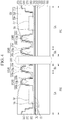
FIG. 1 is a schematic view of a display device according to an embodiment of the present invention; -
FIG. 2 is a view of an area A ofFIG. 1 ; -
FIG. 3 is a cross-sectional view of a display device taken along a line III-III ofFIG. 2 according to an embodiment of the present invention; -
FIG. 4 is a cross-sectional view of a display device according to an embodiment of the present invention; -
FIG. 5 is a cross-sectional view of a display device according to an embodiment of the present invention; -
FIG. 6 is a cross-sectional view of a portion of a first non-display area and a display area in a display device according to an embodiment of the present invention; and -
FIG. 7 is a cross-sectional view of a portion of a first non-display area and a display area including a window in a display device according to an embodiment of the present invention. - The present invention will be described more fully hereinafter with reference to the accompanying drawings. It is to be understood that the described embodiments of the present invention may be modified in various different ways without departing from the scope of the present invention.
- Like reference numerals may denote like elements throughout the specification, and thus repetitive descriptions may be omitted.
- Further, in the drawings, a size and thickness of each element may be exaggerated for clarity, and the present invention is not limited thereto.
- It will be understood that when an element such as a layer, film, area, or substrate is referred to as being "on" another element, it can be directly on the other element or intervening elements may also be present. In addition, when an element is referred to as being "directly on" another element, there are no intervening elements present.
- Further, throughout the specification, the phrase "on a plane" may mean viewing a target portion from the top, and the phrase "on a cross-section" may mean viewing a cross-section formed by vertically cutting a target portion from the side.
- Now, a plan view of a display panel included in a display device according to an embodiment of the present invention is described with reference to
FIG. 1 . -
FIG. 1 is a schematic view of a display device according to an embodiment of the present invention. - A
substrate 100 included in a display panel of a display device according to an embodiment of the present invention includes a display area DA, a through-hole 210, a first non-display area PA1, and a second non-display area PA2. - The display area DA is an area where a plurality of pixels are arranged, thereby being capable of displaying an image. One pixel includes a pixel circuit and an organic light emitting element (OLED) that receives a current from the pixel circuit to emit light.
- The through-
hole 210 is disposed in the display area DA. For example, the through-hole 210 may be formed through thesubstrate 100 and a plurality of insulating layers. The plurality of insulating layers are described in detail with reference toFIG. 2 . At least one camera, flash, photosensor, or the like may be disposed in the through-hole 210. The camera, flash, photosensor, etc. may be disposed in conjunction with a penetrating coupling member disposed within the through-hole 210. InFIG. 1 , the through-hole 210 is circularly formed at a central area of an upper portion of the display area DA, but the position, the shape, and the number of through-holes are not limited. For example, the through-hole 210 can have various shapes such as a polygonal shape, such as a quadrangular shape, or an elliptical shape. - The non-display area includes the first non-display area PA1 and the second non-display area PA2. The first non-display area PA1 is an area at least partially surrounding the perimeter of the through-
hole 210. The first non-display area PA1 is an area between the through-hole 210 and the adjacent display area DA, which is the area at least partially surrounded by the second non-display area PA2. In the first non-display area PA1, a plurality of gate wires GL and a plurality of data wires DL for transmitting signals to the pixel are disposed. Next, the plurality of gate wires GL and data wires DL disposed in the first non-display area PA1 are described with reference toFIG. 2 . - The second non-display area PA2 is the area at least partially surrounding an outer periphery of the display area DA. The second non-display area PA2 is a distinct area that is separated from the first non-display area PA1. A gate driver and a data driver for respectively transmitting signals to a plurality of pixels may be disposed in the second non-display area PA2. The gate driver is a part that applies the gate signal, and may be disposed on one side or both sides facing each other in the horizontal direction (e.g., a widthwise direction) with respect to the display area DA. The data driver is a part to which the data signal is applied, and may be disposed on one side or both sides facing each other in the vertical direction (e.g., a lengthwise direction) with respect to the display area DA.
- Hereinafter, the through-
hole 210 and the first non-display area PA1 are described in detail with reference toFIG. 2 . -
FIG. 2 shows an area A ofFIG. 1 . - The area A of
FIG. 2 includes the through-hole 210, the first non-display area PA1, and the part of the display area DA. - The first non-display area PA1 includes a peripheral area RA and a wiring area LA.
- The peripheral area RA is the inner area of the first non-display area PA1 surrounding the perimeter of the through-
hole 210. The gate wire GL or the data wire DL are not disposed in the peripheral area RA. The peripheral area RA is the area to prevent the wires from being damaged during the laser irradiation to form the through-hole 210, so it is desirable to keep the minimum width constant. - The wiring area LA is the outer (e.g., remaining) area of the first non-display area PA1 surrounding the peripheral area RA. The plurality of gate wires GL and the plurality of data wires DL are disposed in the wiring area LA.
- The gate wire GL and the data wire DL have a semicircular structure around the through-
hole 210 and bypass the through-hole 210. A plurality of gate wires GL extend in the horizontal direction along the perimeter of the through-hole 210. Here, a plurality of gate wires GL may include scan lines, emission control lines, initialization voltage lines, etc. according to supplied signals. A plurality of data wires DL extend in the vertical direction along the perimeter of the through-hole 210. A plurality of data wires DL may include data line, driving voltage lines and driving low voltage lines according to the supplied signal. According to an embodiment of the present invention, the voltage lines of a plurality of gate wires GL and a plurality of data wires DL may be changed. For example, gate wire GL and the data wire DL may be disposed on different layers with the insulating layer in therebetween. - In addition, the peripheral area RA and the wiring area LA surrounding the through-
hole 210 are described with reference toFIG. 3 . -
FIG. 3 is a cross-sectional view taken along a line III-III ofFIG. 2 . - Referring to
FIG. 3 , the organic light emitting display device, according to an embodiment of the present invention, includes asubstrate 100, abarrier layer 110, abuffer layer 120, a gate wire layer, agate insulating layer 130, a data wire layer, aninterlayer insulating layer 140, a middle insulatinglayer 150, anemission layer 370, acathode 270, aplanarization layer 160, apartition 170, aspacer 180, and anencapsulation layer 300. - The
substrate 100 may be made of a material such as glass, metal, or an organic material. According to an embodiment of the present invention, thesubstrate 100 is made of a flexible polyimide PI. Thesubstrate 100 includes the through-hole 210. Here, the through-hole 210 penetrates the plurality of layers disposed on thesubstrate 100 as well as thesubstrate 100, including thebarrier layer 110, thebuffer layer 120, thegate insulating layer 130, theinterlayer insulating layer 140, the middle insulatinglayer 150, theemission layer 370, thecathode 270, theencapsulation layer 300, etc. described later. - The
barrier layer 110 is disposed on thesubstrate 100, and thebuffer layer 120 is disposed on thebarrier layer 110. Thebarrier layer 110 and thebuffer layer 120 may be made of, for example, a silicon oxide (SiOx). A semiconductor layer may be disposed on thebuffer layer 120. On thesubstrate 100, one of thebarrier layer 110 and thebuffer layer 120 may be omitted. - The
gate insulating layer 130 is disposed on thebuffer layer 120. Thegate insulating layer 130 may be made of an inorganic material such as a silicon oxide (SiOx), a silicon nitride (SiNx), or the like. Thegate insulating layer 130 may be disposed to cover the semiconductor layer. - The gate wire layer is disposed on the
gate insulating layer 130. The gate wire layer includes a plurality of gate wires GL, and the plurality of gate wires GL include scan lines to which scan signals are applied, emission control lines to which emission control signals are applied, and initialization voltage lines to which initialization voltages are applied. - The interlayer insulating
layer 140 is disposed on the gate wire layer. The interlayer insulatinglayer 140 may be made of the inorganic material such as a silicon oxide (SiOx) or a silicon nitride (SiNx). - The data wire layer is disposed on the
interlayer insulating layer 140. The data wire layer includes a plurality of data wires DL, and the plurality of data wires DL include data lines to which data voltages are applied, driving voltage lines to which driving voltages are applied, driving low voltage lines to which driving low voltages are applied, etc. In addition, in the data wire layer, a source electrode (hereinafter, 156 ofFIG. 6 ) or a drain electrode (hereinafter, 155 ofFIG. 6 ) of the thin film transistor may be disposed. According to an embodiment of the present invention, the data wire layer may include a first data wire layer and a second data wire layer. The first data wire layer may be disposed on theinterlayer insulating layer 140, and the second data wire layer may be disposed on the middle insulatinglayer 150, described below. - The middle insulating
layer 150 is disposed on the data wire layer. The middle insulatinglayer 150 may be made of an inorganic material. The middle insulatinglayer 150 may be directly contact with theencapsulation layer 300 described later, thereby preventing moisture from penetrating into the organic light emitting element. - The
planarization layer 160, thepartition 170, thespacer 180, and the like, which are each made of an organic material, are disposed on the middle insulatinglayer 150. InFIG. 3 , theplanarization layer 160, thepartition 170, and thespacer 180 are sequentially disposed on both edges of the wiring area LA. Theplanarization layer 160, thepartition 170, and thespacer 180, which are shown only partially on both edges, are portions extending from the wiring area LA to the display area DA, and are described in detail in the cross-sectional view of the display area DA shown inFIG. 6 andFIG. 7 . - In
FIG. 3 , except for the plurality of organic material layers of both edges of the wiring area LA, in the wiring area LA and the peripheral area RA, a first sub-insulating dam DAM1, a second sub-insulating dam DAM2, and a main insulatingdam 55, which are made of the organic material, are disposed on the middle insulatinglayer 150. Here, the first sub-insulating dam DAM1 and the second sub-insulating dam DAM2 provide steps, thereby preventing moisture from penetrating from the through-hole 210 into the organic light emitting element. - The first sub-insulating dam DAM1 is disposed in the peripheral area RA. The first sub-insulating dam DAM1 includes a
first planarization part 160a, afirst partition part 170a, and afirst spacer part 180a. Thefirst planarization part 160a is disposed on the middle insulatinglayer 150. In addition, thefirst partition part 170a is disposed on thefirst planarization part 160a, and thefirst spacer part 180a is disposed on thefirst partition part 170a. Thefirst planarization part 160a may be disposed on the same layer as theplanarization layer 160. In addition, thefirst partition part 170a may be disposed on the same layer as thepartition 170, and thefirst spacer part 180a may be disposed on the same layer as thespacer 180. According to an embodiment of the present invention, the first sub-insulating dam DAM1 may include thefirst partition part 170a and thefirst spacer part 180a, thefirst planarization part 160a and thefirst spacer part 180a, or thefirst planarization part 160a and thefirst partition part 170a. - The second sub-insulating dam DAM2 is disposed in the wiring area LA. The second sub-insulating dam DAM2 includes a
second planarization part 160b, asecond partition part 170b, and asecond spacer part 180b. Thesecond planarization part 160b may be disposed on the same layer as thefirst planarization part 160a. In addition, thesecond partition part 170b may be disposed on the same layer as thefirst partition part 170a, and thesecond spacer part 180b may be disposed on the same layer as thefirst spacer part 180a. According to an embodiment of the present invention, the second sub-insulating dam DAM2 may include thesecond partition part 170b and thesecond spacer part 180b. In addition, according to an embodiment of the present invention, in the wiring area LA, a plurality of insulation dams may be formed on the same layer as the organic material layer of one of theplanarization layer 160, thepartition 170, or thespacer 180. According to an embodiment of the present invention, thespacer 180 may be formed when thepartition 170 is formed. - The main insulating
dam 55 is disposed in the wiring area LA. The main insulatingdam 55 in the wiring area LA is referred to as a first main insulating dam. The main insulatingdam 55 disconnects the emission layers 370 and disconnects thecathode 270, extending in the wiring area LA, thereby preventing moisture inflowed from the through-hole 210 from being transmitted to the organic light emitting element OLED of the display area DA. For example, in an embodiment of the present invention, the main insulatingdam 55 may separate theemission layer 370 to form a disconnection in theemission layer 370 to further prevent the inflow of moisture from the through-hole 210 to the organic light emitting element OLED. For example, the disconnection part SA, formed in theemission layer 370 and thecathode 270 by the main insulatingdam 55, disposed in the wiring area LA may prevent moisture from penetrating into the organic emission layer located in the display area DA. The main insulatingdam 55 may be formed together with one of theplanarization layer 160, thepartition 170, or thespacer 180, and may be formed of a single layer or a plurality of organic layers. For example, the main insulatingdam 55 is implemented with a shape of which a width of the lower surface is narrower a width of the upper surface. For example, a reverse tapered shape, an inverted trapezoid shape, a "T" shape, an under-cut shape, or the like may be formed. According to an embodiment of the present invention, the main insulatingdam 55 may be formed as a plurality of dams of different sized shapes and/or different shapes. - The
emission layer 370 is disposed on the main insulatingdam 55, the first sub-insulating dam DAM1, and the second sub-insulating dam DAM2. Thecathode 270 is disposed above theemission layer 370. Here, the emission layers 370 and thecathode 270 may form the organic light emitting element (OLED) together with an anode to be described later (hereinafter, 191 ofFIG. 6 ,). Theemission layer 370 and thecathode 270 are formed over thesubstrate 100 to cover the main insulatingdam 55 disposed on the middle insulatinglayer 150. In addition, theemission layer 370 and thecathode 270 are formed over the first sub-insulating dam DAM1 and the second sub-insulating dam DAM2. Further, as an example, theemission layer 370 and thecathode 270 may be formed over the entire surface of the substrate. According to an embodiment of the present invention, theemission layer 370 may be formed in some areas of thesubstrate 100. - According to an embodiment of the present invention, the
emission layer 370 and thecathode 270 are formed on the upper surface of the main insulatingdam 55 and are not formed on the side surface of the main insulatingdam 55 having the reverse tapered shape. Theemission layer 370 and thecathode 270 include the disconnection part SA as a result of the main insulatingdam 55. Thus, the main insulatingdam 55 disconnects theemission layer 370 or thecathode 270 extending from the display area DA into the wiring area LA, thereby preventing moisture, inflowed from the through-hole 210, from being transmitted to the organic light emitting element OLED of the display area DA. The disconnection part SA is a part where the middle insulatinglayer 150 and anencapsulation layer 300 described later are in direct contact with each other. The disconnection part SA may prevent moisture (H2O) from penetrating along the interface direction between the layers (e.g., a direction parallel to an upper surface of the substrate 100). - In a display device according to a comparative example, an insulating dam of a relatively large size is disposed in the peripheral area RA and the wiring area LA to form the disconnection portion of the
cathode 270 or theemission layer 370, as the first non-display area PA1 is on the perimeter of the through-hole 210. - In contrast, in the display device according to an embodiment of the present invention, by forming the disconnection part SA of the
cathode 270 or theemission layer 370 in the wiring area LA, the first non-display area PA1 on the perimeter of the through-hole 210 may be reduced. - The
encapsulation layer 300 is disposed on thecathode 270. Theencapsulation layer 300 includes a firstinorganic encapsulation layer 310, anorganic encapsulation layer 320, and a secondinorganic encapsulation layer 330. The firstinorganic encapsulation layer 310 and the secondinorganic encapsulation layer 330 are formed throughout the non-display area PA1 and PA2 and the display area DA. In addition, theorganic encapsulation layer 320 may be formed on a part of the display area DA and a part of the wiring area LA. For example, theorganic encapsulation layer 320 might not be formed in the peripheral area RA. In a part of the wiring area LA and the peripheral area RA, the firstinorganic encapsulation layer 310 and the secondinorganic encapsulation layer 330 are in direct contact with each other. According to an embodiment of the present invention, a plurality of inorganic layers and organic layers may be included to prevent moisture penetration. - The first
inorganic encapsulation layer 310 can directly contact the middle insulatinglayer 150 in the disconnection part SA to prevent the moisture, that may penetrate along the interface between the layers, from inflowing into the organic light emitting element (OLED). - Hereinafter, the display device without including the main insulating
dam 55 ofFIG. 3 is described with reference toFIG. 4 . -
FIG. 4 is a cross-sectional view of a display device according to an embodiment of the present invention. - In
FIG. 4 , since the display device according to an embodiment of the present invention is the same as that described inFIG. 3 except for the opening OP of theemission layer 370 and thecathode 270, the differences are mainly described. - A first sub-insulating dam DAM1 and a second sub-insulating dam DAM2, which are made of organic material, are disposed on the middle insulating
layer 150. Here, the first sub-insulating dam DAM1 and the second sub-insulating dam DAM2 provide steps to prevent the moisture, which is from the through-hole 210, from penetrating into the organic light emitting element (OLED). - The
emission layer 370 is disposed on the first sub-insulating dam DAM1 and the second sub-insulating dam DAM2, and thecathode 270 is disposed on theemission layer 370. Theemission layer 370 and thecathode 270 are formed over thesubstrate 100 to cover all of the first sub-insulating dam DAM1 and the second sub-insulating dam DAM2 on the middle insulatinglayer 150. In addition, a part of theemission layer 370 and a part of thecathode 270 disposed in the wiring area LA is disconnected by a laser irradiation process. Thus, theemission layer 370 and thecathode 270 include the opening OP. Here, both sides of the opening OP may be referred to as the disconnection part SA. The disconnection part SA is a portion in which the middle insulatinglayer 150 and the firstinorganic encapsulation layer 310 described later directly contact each other. In the disconnection part SA formed in the wiring area LA, since thecathode 270 and theemission layer 370 are disconnected, the moisture inflowed from the through-hole 210 may not be transmitted to the organic light emitting element (OLED) in the display area DA. For example, the disconnection part SA formed in the wiring area LA may prevent moisture from being transferred to theorganic emission layer 370 located in the display area DA. - In addition, the display device according to an embodiment of the present invention may reduce the first non-display area PA1 around the perimeter of the through-
hole 210 by forming the disconnection part SA of thecathode 270 and/or theemission layer 370 in the wiring area LA. - Hereinafter, the display device further including a plurality of main insulating
dams 55 in the peripheral area RA without including the first sub-insulating dam DAM1, unlike inFIG. 3 , is described with reference toFIG. 5 . -
FIG. 5 is a cross-sectional view of a display device according to an embodiment of the present invention. - In
FIG. 5 , since the display device according to an embodiment of the present invention includes a plurality of main insulatingdams FIG. 3 , are mainly described. - The second sub-insulating dam DAM2 and a plurality of main insulating
dams layer 150. The second sub-insulating dam DAM2 and a plurality of main insulatingdams hole 210 to the organic light emitting element (OLED). - The second sub-insulating dam DAM2 is disposed in the wiring area LA and includes the
second planarization part 160b, thesecond partition part 170b, and thesecond spacer part 180b. According to an embodiment of the present invention, the second sub-insulating dam DAM2 may include thesecond partition part 170b and thesecond spacer part 180b. - A plurality of main insulating
dams dams FIG. 5 , two main insulatingdams dams dams emission layer 370 and disconnect thecathode 270 so that the moisture inflowed from the through-hole 210 may not be transmitted to the organic light emitting element OLED of the display area DA. The main insulatingdams planarization layer 160, thepartition 170, or thespacer 180, and may be formed of a single layer or a plurality of organic layers. The main insulatingdams dams - The
emission layer 370 is disposed on the main insulatingdams cathode 270 is disposed on theemission layer 370. Here, the emission layers 370 and thecathode 270 may form the organic light emitting element (OLED) together with the anode to be described later (hereinafter, 191 ofFIG. 6 ). The emission layers 370 and thecathode 270 are formed over thesubstrate 100 to cover both the main insulatingdams layer 150. However, the emission layers 370 ans thecathode 270 are formed only on the upper surfaces of the main insulatingdams dams dams emission layer 370 and thecathode 270 include the disconnection part SA as a result of the main insulatingdams dams emission layer 370 or thecathode 270 in the peripheral area RA and the wiring area LA, thereby preventing the moisture inflowed from the through-hole 210 from penetrating the organic light emitting element (OLED). In an embodiment of the present invention, the disconnection part SA is the portion in which the middle insulatinglayer 150 and the firstinorganic encapsulation layer 310 may directly contact each other. The disconnection part SA may prevent the moisture (H2O) from penetrating the organic light emitting element (OLED) in the display area DA along the interface direction between the layers. - In addition, the display device according to an embodiment of the present invention may reduce the first non-display area PA1 around the perimeter of the through-
hole 210 by disposing the main insulatingdam 55 of the smaller size than the first and second sub-insulating dams DAM1 and DAM2 in the peripheral area RA and the wiring area LA to form the disconnection portion of thecathode 270 or theemission layer 370. - The
encapsulation layer 300 is disposed on thecathode 270. Theencapsulation layer 300 includes a firstinorganic encapsulation layer 310, anorganic encapsulation layer 320, and a secondinorganic encapsulation layer 330. Theencapsulation layer 300 is the layer to cover thesubstrate 100 for preventing moisture from penetrating into the organic light emitting element (OLED), and may have a structure that blocks moisture penetration by including the plurality of inorganic layers and organic layers according to an embodiment. - The first
inorganic encapsulation layer 310 may directly contact the middle insulatinglayer 150 in the disconnection part SA to prevent moisture inflow that may penetrate along the interface between the layers to the organic light emitting element (OLED). - Hereinafter, the display device including the through-
hole 210, the first non-display area PA1, and the display area DA is described with reference toFIG. 6 . -
FIG. 6 is a cross-sectional view showing a first non-display area and a part of a display area in a display device according to an embodiment of the present invention. - Referring to
FIG. 6 , the display device according to an embodiment of the present invention includes thebarrier layer 110, thebuffer layer 120, asemiconductor layer 121, the gate wire layer, thegate insulating layer 130, the data wire layer, theinterlayer insulating layer 140, the middle insulatinglayer 150, theemission layer 370, thecathode 270, a plurality of organic layers, and theencapsulation layer 300, which are sequentially disposed on thesubstrate 100. Thesubstrate 100, thebarrier layer 110, thebuffer layer 120, thegate insulating layer 130, theinterlayer insulating layer 140, the middle insulatinglayer 150, theemission layer 370, thecathode 270, and theencapsulation layer 300 are formed over the peripheral area RA, the wiring area LA, and the display area DA. Here, thesubstrate 100, thebarrier layer 110, thebuffer layer 120, thegate insulating layer 130, theinterlayer insulating layer 140, and the middle insulatinglayer 150 are the same as described inFIG. 3 , and therefore further description thereof may be omitted. - The
substrate 100 includes the through-hole 210. Here, the through-hole 210 penetrates the plurality of layers disposed on thesubstrate 100, which include thebarrier layer 110, thebuffer layer 120, thegate insulating layer 130, theinterlayer insulating layer 140, the middle insulatinglayer 150, theemission layer 370, thecathode 270, theencapsulation layer 300, etc. described later, in addition to thesubstrate 100. - The
barrier layer 110 is disposed on thesubstrate 100, and thebuffer layer 120 is disposed on thebarrier layer 110. - In the display area DA, a thin film transistor is disposed on the
buffer layer 120. The thin film transistor includes thesemiconductor layer 121, agate electrode 131, thesource electrode 156, and thedrain electrode 155. Thegate insulating layer 130 is disposed between thesemiconductor layer 121 and thegate electrode 131. The interlayer insulatinglayer 140 is disposed on thegate electrode 131, and thesource electrode 156 and thedrain electrode 155 are disposed on theinterlayer insulating layer 140. The middle insulatinglayer 150 is disposed over the interlayer insulatinglayer 140 to cover thesource electrode 156 and thedrain electrode 155. - The
semiconductor layer 121 may include, for example, amorphous silicon, polycrystalline silicon, or an oxide semiconductor. - The
gate insulating layer 130 and the interlayer insulatinglayer 140 may include, for example, an inorganic material including an oxide or nitride. - The
gate electrode 131, thesource electrode 156, anddrain electrode 155 may include, for example, a low resistance metal material. - The
gate electrode 131 is included in the gate wire layer, and the gate wire layer in the first non-display area PA1 includes a plurality of gate wires GL. - The
source electrode 156 and thedrain electrode 155 are connected to thesemiconductor layer 121 through a contact hole formed in theinterlayer insulating layer 140. Thesource electrode 156 and thedrain electrode 155 are included in the data wire layer, and the data wire layer in the first non-display area PA1 includes a plurality of data wires DL. - The middle insulating
layer 150 is disposed on theinterlayer insulating layer 140 to cover thesource electrode 156,drain electrode 155, and a plurality of data wires DL. The middle insulatinglayer 150 may be made of an inorganic material, and may include a portion in direct contact with theencapsulation layer 300 to prevent moisture from penetrating into the organic light emitting element (OLED). - The
planarization layer 160 made of the organic material is disposed on the middle insulatinglayer 150. Theplanarization layer 160 is formed throughout the display area DA and the non-display area PA1 and PA2. Theplanarization layer 160 includes afirst planarization layer 161 and asecond planarization layer 162. - The
first planarization layer 161 is disposed on the middle insulatinglayer 150. - An upper data wire layer is disposed on the
first planarization layer 161. The upper data wire layer includes a plurality of upper data electrodes. Among the plurality of the upper data electrodes, a firstupper data electrode 41 is electrically connected to the data wire DL through acontact hole 63 formed in thefirst planarization layer 161, and a secondupper data electrode 42 is electrically connected to thedrain electrode 155, and/or thesource electrode 156 through acontact hole 63 formed in thefirst planarization layer 161. - The
second planarization layer 162 is disposed on thefirst planarization layer 161 and is formed to cover the upper data wire layer including the firstupper data electrode 41. The firstupper data electrode 41 is disposed such that its upper surface is exposed through anopening 61 formed in thesecond planarization layer 162. - The
anode 191 is disposed on thesecond planarization layer 162. Theanode 191 forms the organic light emitting element (OLED) together with theemission layer 370 and thecathode 270. Afirst anode 191a is in direct contact with the upper surface of the firstupper data electrode 41 through theopening 61 formed in thesecond planarization layer 162 to be electrically connected to each other. Asecond anode 191b is electrically connected to the secondupper data electrode 42 through acontact hole 62 formed in thesecond planarization layer 162. The secondupper data electrode 42 is connected to thedrain electrode 155 through thecontact hole 63 formed in thefirst planarization layer 161. Thus, theanode 191 may be connected to thedrain electrode 155 of the thin film transistor. - The
partition 170 is disposed on theanode 191. Thepartition 170 includes anopening 64 exposing theanode 191. Red, blue, and green emission layers 370R, 370B, and 370G are disposed in theopening 64 of thepartition 170 disposed in the display area DA. The red, blue, and green emission layers 370R, 370B, and 370G may include an organic light emitting material or an inorganic light emitting material. InFIG. 6 , the red, blue, and green emission layers 370R, 370B, and 370G are shown, but the positions of the red, blue, and green emission layers 370R, 370B, and 370G may be varied depending on an embodiment of the present invention. In addition, the red, blue, and green emission layers 370R, 370B, and 370G may refer to some areas of theemission layer 370 formed in the display area DA among theemission layer 370. - In the first non-display area PA1, the
partition 170 includes thefirst partition part 170a and athird partition part 170c. Thefirst partition part 170a is disposed on thesecond planarization layer 162, and athird partition part 170c disposed on theanode 191a. Thefirst partition part 170a may form one insulation dam with thefirst planarization part 160a. For example, thefirst planarization part 160a may be a part of thefirst planarization layer 161 and a part of thesecond planarization layer 162. -
Upper spacers partition 170. Theupper spacers upper spacers cathode 270 to prevent moisture, inflowed from the through-hole 210, from penetrating the organic light emitting element (OLED) in the display area DA. Theupper spacers upper spacers upper spacers - In
FIG. 6 , theupper spacers upper spacer 181, a secondupper spacer 182, and a thirdupper spacer 183 respectively disposed in the peripheral area RA, the wiring area LA, and the display area DA. The firstupper spacer 181 is included in the first reverse insulating dam DAM1 in the peripheral area RA together with thefirst planarization part 160a and thefirst partition part 170a. The secondupper spacer 182 includes a reverse insulating dam in the wiring area LA along with thethird partition part 170c. The thirdupper spacer 183 may be formed of a single layer of the reverse insulating dam in the display area DA. - The
emission layer 370 is disposed to cover theupper spacers partition 170, theplanarization layer 160, theanode 191, and the red, blue, and green emission layers 370R, 370B, and 370G. Thecathode 270 is disposed on theemission layer 370. Theemission layer 370 and thecathode 270 are formed to cover the surface of thesubstrate 100. However, the emission layers 370 and thecathode 270 are formed only on the upper surfaces of theupper spacers cathode 270 are not formed on the sides of theupper spacers emission layer 370 and thecathode 270 include a plurality of disconnection portions SA based on theupper spacers upper spacer 180 disconnects theemission layer 370 or thecathode 270 extending to the display area DA to protect the display element from moisture. In an embodiment of the present invention, at the disconnection part SA, the middle insulatinglayer 150 and theencapsulation layer 300 may be in direct contact with each other. The disconnection part SA may prevent moisture (H2O) from penetrating along the interface direction between the layers. - An
encapsulation layer 300 is disposed on thecathode 270. Theencapsulation layer 300 includes the firstinorganic encapsulation layer 310, theorganic encapsulation layer 320, and the secondinorganic encapsulation layer 330. Theencapsulation layer 300 is a layer that may prevent moisture from penetrating into the organic light emitting element (OLED) layer and that covers thesubstrate 100. According to an embodiment of the present invention, theencapsulation layer 300 may have a structure that prevents moisture penetration by including a plurality of inorganic layers and organic layers. - The first
inorganic encapsulation layer 310 may overlap the middle insulatinglayer 150 at the disconnection portion SA. For example, at the disconnection portion SA, the firstinorganic encapsulation layer 310 may directly contact the middle insulatinglayer 150 to prevent moisture inflow into the organic light emitting element (OLED) that may penetrate along the interface between the layers. Therefore, the moisture is prevented from penetrating from the through-hole 210 to the organic light emitting element (OLED). - Next, the display device according to an embodiment of the present invention, in
FIG. 7 , further includes awindow 200, unlike the display device ofFIG. 6 . -
FIG. 7 is a cross-sectional view of a portion of a first non-display area and a display area of a display device including a window according to an embodiment of the present invention. - Referring to
FIG. 7 , thewindow 200 is disposed at the top of the display device and may protect various configurations disposed in the lower part of the display device. In addition, thewindow 200 is made of a transparent material to transmit the internal light generated inside the display device to the outside so that the image may be visually recognized from the outside. Thewindow 200 is disposed on the upper surface of the secondinorganic encapsulation layer 330. For example, thewindow 200 may be attached to secondinorganic encapsulation layer 330 by an adhesive layer. Since thewindow 200 is formed over the upper surface of the display device, the open area of the through-hole 210 may be protected by thewindow 200. In addition, a light generated from a camera, a flash, a photosensor, or the like, which may be disposed in the through-hole 210, may be transmitted to the outside through thewindow 200. - While the present invention has been shown and described with reference to the embodiments thereof, it will be apparent to those of ordinary skill in the art that various changes in form and detail may be made thereto without departing from the scope of the present invention.
Claims (10)
- A display device comprising:a substrate (100) including a through-hole (210) , a peripheral area (RA) surrounding the through-hole (210), a wiring area (LA) surrounding the peripheral area (RA), and a display area (DA) surrounding the wiring area (LA);a gate insulating layer (130) disposed on the substrate (100);a gate wire (GL) disposed in the wiring area (LA) and on the gate insulating layer (130);an interlayer insulating layer (140) disposed on the gate wire (GL);a data wire (DL) disposed in the wiring area (LA) and on the interlayer insulating layer (140);a middle insulating layer (150) disposed on the data wire (DL); anda first main insulating dam (55) disposed in the wiring area (LA) and on the middle insulating layer (150),wherein the first main insulating dam (55) includes an organic material, and wherein a width of a lower surface of the first main insulating dam (55) is narrower than a width of an upper surface of the first main insulating dam (55).
- The display device of claim 1, further comprising:an emission layer (370) disposed on the substrate (100); anda cathode (270) disposed on the emission layer (370),wherein the emission layer (370) and the cathode (270) are disposed in the peripheral area (RA) and the wiring area (LA), andthe emission layer (370) and the cathode (270) include a disconnection point based on the first main insulating dam (55).
- The display device of claim 2, further comprising:an encapsulation layer (300) disposed on the cathode (270),wherein the encapsulation layer (300) includes an inorganic encapsulation layer (310) and an organic encapsulation layer(320).
- The display device of claim 3, wherein
the middle insulating layer (150) and the inorganic encapsulation layer (310) are in direct contact at the disconnection point. - The display device of at least one of claims 1 to 4, further comprising:a first sub-insulating dam (DAM1) disposed in the peripheral area (RA) and disposed on the middle insulating layer (150),wherein the first sub-insulating dam (DAM1) includes a plurality of organic layers.
- The display device of claim 5, wherein
the plurality of organic layers include:a planarization layer (160) disposed on the middle insulating layer (150);a partition (170) disposed on the planarization layer (160); anda spacer (180) disposed on the partition (170). - The display device of claim 5 or 6, further comprising
a second sub-insulating dam (DAM2) disposed in the wiring area (LA) and on the middle insulating layer (150),
wherein the second sub-insulating dam (DAM2) includes the plurality of organic layers. - The display device of claim 6 or 7, wherein
the first main insulating dam (55) is disposed on a same layer as one of the planarization layer (160), the partition (170), or the spacer (180). - The display device of at least one of claims 1 to 8, further comprising at least one second main insulating dam (55c, 55d) disposed in the peripheral area (RA).
- The display device of at least one of claims 1 to 9, wherein
the through-hole (210) is formed to penetrate the substrate (100), the gate insulating layer (130), the interlayer insulating layer (140), and the middle insulating layer (150).
Applications Claiming Priority (1)
| Application Number | Priority Date | Filing Date | Title |
|---|---|---|---|
| KR1020190034936A KR102798030B1 (en) | 2019-03-27 | 2019-03-27 | Display device |
Publications (2)
| Publication Number | Publication Date |
|---|---|
| EP3716337A1 true EP3716337A1 (en) | 2020-09-30 |
| EP3716337B1 EP3716337B1 (en) | 2023-03-22 |
Family
ID=70049933
Family Applications (1)
| Application Number | Title | Priority Date | Filing Date |
|---|---|---|---|
| EP20165989.3A Active EP3716337B1 (en) | 2019-03-27 | 2020-03-26 | Display device with hole |
Country Status (4)
| Country | Link |
|---|---|
| US (2) | US10930867B2 (en) |
| EP (1) | EP3716337B1 (en) |
| KR (1) | KR102798030B1 (en) |
| CN (1) | CN111755484B (en) |
Families Citing this family (31)
| Publication number | Priority date | Publication date | Assignee | Title |
|---|---|---|---|---|
| JP6985983B2 (en) * | 2018-05-31 | 2021-12-22 | 株式会社ジャパンディスプレイ | Display device |
| KR102168042B1 (en) | 2018-12-27 | 2020-10-20 | 엘지디스플레이 주식회사 | Display Device |
| KR102798030B1 (en) | 2019-03-27 | 2025-04-18 | 삼성디스플레이 주식회사 | Display device |
| US12022680B2 (en) * | 2019-04-05 | 2024-06-25 | Sharp Kabushiki Kaisha | Display device |
| CN110085553B (en) * | 2019-04-22 | 2021-06-22 | 武汉华星光电半导体显示技术有限公司 | OLED array substrate and manufacturing method thereof |
| CN110165083A (en) * | 2019-05-31 | 2019-08-23 | 武汉华星光电半导体显示技术有限公司 | A kind of display panel |
| CN110212113B (en) * | 2019-05-31 | 2021-11-09 | 京东方科技集团股份有限公司 | Electroluminescent display substrate, preparation method thereof and electroluminescent display device |
| CN110828515A (en) * | 2019-10-25 | 2020-02-21 | 武汉华星光电技术有限公司 | Display device and preparation method thereof |
| KR102929425B1 (en) | 2020-01-02 | 2026-02-23 | 삼성디스플레이 주식회사 | Display apparatus |
| KR102867065B1 (en) * | 2020-07-20 | 2025-10-13 | 엘지디스플레이 주식회사 | Display Device and Repairing Method thereof |
| CN112349866A (en) * | 2020-10-27 | 2021-02-09 | 京东方科技集团股份有限公司 | Display panel, manufacturing method thereof and display device |
| KR102886551B1 (en) * | 2020-10-27 | 2025-11-14 | 삼성디스플레이 주식회사 | Display device |
| KR102792881B1 (en) | 2020-11-12 | 2025-04-08 | 삼성디스플레이 주식회사 | Display device |
| KR102773867B1 (en) * | 2020-12-18 | 2025-02-26 | 엘지디스플레이 주식회사 | Display apparatus |
| KR20220090956A (en) | 2020-12-23 | 2022-06-30 | 엘지디스플레이 주식회사 | Display device |
| KR102923821B1 (en) * | 2020-12-29 | 2026-02-04 | 엘지디스플레이 주식회사 | Display apparatus |
| CN112736093B (en) * | 2020-12-30 | 2022-10-04 | 武汉华星光电半导体显示技术有限公司 | Display panel and display device |
| KR102945598B1 (en) * | 2020-12-31 | 2026-03-27 | 엘지디스플레이 주식회사 | Light emitting display apparatus and multi screen display apparatus using the same |
| CN112802979A (en) * | 2021-01-11 | 2021-05-14 | 合肥维信诺科技有限公司 | Display panel and preparation method thereof |
| KR102952961B1 (en) | 2021-01-29 | 2026-04-15 | 삼성디스플레이 주식회사 | Display device |
| CN116917970A (en) * | 2021-02-26 | 2023-10-20 | 株式会社日本显示器 | display device |
| JP2022164048A (en) | 2021-04-15 | 2022-10-27 | キヤノン株式会社 | Semiconductor device, display, imaging apparatus, and electronic apparatus |
| JP2022175716A (en) * | 2021-05-14 | 2022-11-25 | 株式会社ジャパンディスプレイ | Display device |
| KR20230064075A (en) * | 2021-11-02 | 2023-05-10 | 삼성디스플레이 주식회사 | Display device |
| KR20230076400A (en) * | 2021-11-24 | 2023-05-31 | 엘지디스플레이 주식회사 | Display device |
| CN114156421B (en) * | 2021-12-02 | 2024-02-13 | 云谷(固安)科技有限公司 | Display panels and display devices |
| KR20230082802A (en) * | 2021-12-02 | 2023-06-09 | 엘지디스플레이 주식회사 | Display device |
| KR20230100397A (en) | 2021-12-28 | 2023-07-05 | 엘지디스플레이 주식회사 | Display device |
| CN114464754B (en) * | 2022-01-25 | 2023-05-12 | 武汉华星光电半导体显示技术有限公司 | Display panel and display device |
| KR20240034933A (en) * | 2022-09-07 | 2024-03-15 | 삼성디스플레이 주식회사 | Display device and method of manufacturing the same |
| CN119866135A (en) * | 2023-10-20 | 2025-04-22 | 合肥维信诺科技有限公司 | Display panel and display device |
Citations (1)
| Publication number | Priority date | Publication date | Assignee | Title |
|---|---|---|---|---|
| US20170237038A1 (en) * | 2016-02-16 | 2017-08-17 | Samsung Display Co., Ltd. | Organic light-emitting display apparatus and fabrication method thereof |
Family Cites Families (13)
| Publication number | Priority date | Publication date | Assignee | Title |
|---|---|---|---|---|
| KR102326069B1 (en) * | 2015-07-29 | 2021-11-12 | 엘지디스플레이 주식회사 | Organic light emitting display device |
| KR102427249B1 (en) * | 2015-10-16 | 2022-08-01 | 삼성디스플레이 주식회사 | display device |
| KR102528294B1 (en) * | 2015-11-12 | 2023-05-04 | 삼성디스플레이 주식회사 | Organic light emitting display and manufacturing method thereof |
| KR102552272B1 (en) | 2015-11-20 | 2023-07-07 | 삼성디스플레이 주식회사 | Organic light emitting display and manufacturing method using the same |
| KR102457252B1 (en) * | 2015-11-20 | 2022-10-24 | 삼성디스플레이 주식회사 | Organic light emitting display and manufacturing method using the same |
| US10205122B2 (en) | 2015-11-20 | 2019-02-12 | Samsung Display Co., Ltd. | Organic light-emitting display and method of manufacturing the same |
| KR102490891B1 (en) * | 2015-12-04 | 2023-01-25 | 삼성디스플레이 주식회사 | Display device |
| JP2017108065A (en) * | 2015-12-11 | 2017-06-15 | 株式会社半導体エネルギー研究所 | Method of manufacturing semiconductor device, and method of manufacturing display device having the semiconductor device |
| KR102526110B1 (en) | 2016-04-12 | 2023-04-27 | 삼성디스플레이 주식회사 | Display apparatus and method of manufacturing display apparatus |
| JP6807223B2 (en) * | 2016-11-28 | 2021-01-06 | 株式会社ジャパンディスプレイ | Display device |
| CN107123621A (en) * | 2017-05-10 | 2017-09-01 | 京东方科技集团股份有限公司 | A kind of OLED touch-control display panels and preparation method thereof, touch control display apparatus |
| CN107393940B (en) * | 2017-09-06 | 2020-02-21 | 严光能 | LED display device and manufacturing method thereof |
| KR102798030B1 (en) | 2019-03-27 | 2025-04-18 | 삼성디스플레이 주식회사 | Display device |
-
2019
- 2019-03-27 KR KR1020190034936A patent/KR102798030B1/en active Active
-
2020
- 2020-03-11 US US16/815,117 patent/US10930867B2/en active Active
- 2020-03-26 EP EP20165989.3A patent/EP3716337B1/en active Active
- 2020-03-27 CN CN202010228940.1A patent/CN111755484B/en active Active
-
2021
- 2021-02-18 US US17/178,384 patent/US11611050B2/en active Active
Patent Citations (1)
| Publication number | Priority date | Publication date | Assignee | Title |
|---|---|---|---|---|
| US20170237038A1 (en) * | 2016-02-16 | 2017-08-17 | Samsung Display Co., Ltd. | Organic light-emitting display apparatus and fabrication method thereof |
Also Published As
| Publication number | Publication date |
|---|---|
| US20200313102A1 (en) | 2020-10-01 |
| CN111755484A (en) | 2020-10-09 |
| US10930867B2 (en) | 2021-02-23 |
| CN111755484B (en) | 2025-03-11 |
| US11611050B2 (en) | 2023-03-21 |
| KR102798030B1 (en) | 2025-04-18 |
| US20210175446A1 (en) | 2021-06-10 |
| EP3716337B1 (en) | 2023-03-22 |
| KR20200113957A (en) | 2020-10-07 |
Similar Documents
| Publication | Publication Date | Title |
|---|---|---|
| EP3716337B1 (en) | Display device with hole | |
| US11895886B2 (en) | Display device with insulating layer in through hole or notch | |
| US11038141B2 (en) | Semiconductor device | |
| US12464904B2 (en) | Display apparatus having substrate hole | |
| US10204846B2 (en) | Display device | |
| US20220359641A1 (en) | Display device having light transmissive regions | |
| US10206276B2 (en) | Flexible display and method of manufacturing the same | |
| KR102614612B1 (en) | Flat Panel Display Connecting Front Side to Rear Side of Substrate Using Through Hole | |
| US11903285B2 (en) | Display device and electronic device with peripheral connection to cathode electrode | |
| EP3346501A1 (en) | Organic light emitting display device having a connecting clad electrode | |
| KR102392993B1 (en) | Organic light emitting display device | |
| US10923558B2 (en) | Display device and method of manufacturing display device | |
| US9704933B2 (en) | Organic electroluminescent device | |
| JP2018005160A (en) | Display device | |
| CN106067471A (en) | Display device and manufacture method thereof | |
| KR20190034902A (en) | Display device having an auxiliary electrode | |
| US10345943B2 (en) | Display device | |
| CN114613806A (en) | Display device | |
| KR20160013443A (en) | Bottom Emission Type Organic Light Emission Diode Display Having Color Filters And Method For Manufacturing The Same | |
| JP6807235B2 (en) | Display device | |
| US12250848B2 (en) | Display apparatus including substrate hole | |
| KR20220069170A (en) | Display device and method for fabricating the same | |
| KR20240119647A (en) | Display apparatus having link wirings | |
| CN118284117A (en) | Display device | |
| KR20230095215A (en) | Display apparatus |
Legal Events
| Date | Code | Title | Description |
|---|---|---|---|
| PUAI | Public reference made under article 153(3) epc to a published international application that has entered the european phase |
Free format text: ORIGINAL CODE: 0009012 |
|
| STAA | Information on the status of an ep patent application or granted ep patent |
Free format text: STATUS: THE APPLICATION HAS BEEN PUBLISHED |
|
| AK | Designated contracting states |
Kind code of ref document: A1 Designated state(s): AL AT BE BG CH CY CZ DE DK EE ES FI FR GB GR HR HU IE IS IT LI LT LU LV MC MK MT NL NO PL PT RO RS SE SI SK SM TR |
|
| AX | Request for extension of the european patent |
Extension state: BA ME |
|
| STAA | Information on the status of an ep patent application or granted ep patent |
Free format text: STATUS: REQUEST FOR EXAMINATION WAS MADE |
|
| 17P | Request for examination filed |
Effective date: 20210326 |
|
| RBV | Designated contracting states (corrected) |
Designated state(s): AL AT BE BG CH CY CZ DE DK EE ES FI FR GB GR HR HU IE IS IT LI LT LU LV MC MK MT NL NO PL PT RO RS SE SI SK SM TR |
|
| STAA | Information on the status of an ep patent application or granted ep patent |
Free format text: STATUS: EXAMINATION IS IN PROGRESS |
|
| 17Q | First examination report despatched |
Effective date: 20210804 |
|
| GRAP | Despatch of communication of intention to grant a patent |
Free format text: ORIGINAL CODE: EPIDOSNIGR1 |
|
| STAA | Information on the status of an ep patent application or granted ep patent |
Free format text: STATUS: GRANT OF PATENT IS INTENDED |
|
| INTG | Intention to grant announced |
Effective date: 20221007 |
|
| GRAS | Grant fee paid |
Free format text: ORIGINAL CODE: EPIDOSNIGR3 |
|
| GRAA | (expected) grant |
Free format text: ORIGINAL CODE: 0009210 |
|
| STAA | Information on the status of an ep patent application or granted ep patent |
Free format text: STATUS: THE PATENT HAS BEEN GRANTED |
|
| AK | Designated contracting states |
Kind code of ref document: B1 Designated state(s): AL AT BE BG CH CY CZ DE DK EE ES FI FR GB GR HR HU IE IS IT LI LT LU LV MC MK MT NL NO PL PT RO RS SE SI SK SM TR |
|
| REG | Reference to a national code |
Ref country code: GB Ref legal event code: FG4D |
|
| REG | Reference to a national code |
Ref country code: CH Ref legal event code: EP |
|
| REG | Reference to a national code |
Ref country code: IE Ref legal event code: FG4D |
|
| REG | Reference to a national code |
Ref country code: DE Ref legal event code: R096 Ref document number: 602020008940 Country of ref document: DE |
|
| REG | Reference to a national code |
Ref country code: AT Ref legal event code: REF Ref document number: 1555824 Country of ref document: AT Kind code of ref document: T Effective date: 20230415 |
|
| REG | Reference to a national code |
Ref country code: NL Ref legal event code: FP |
|
| P01 | Opt-out of the competence of the unified patent court (upc) registered |
Effective date: 20230516 |
|
| REG | Reference to a national code |
Ref country code: LT Ref legal event code: MG9D |
|
| PG25 | Lapsed in a contracting state [announced via postgrant information from national office to epo] |
Ref country code: RS Free format text: LAPSE BECAUSE OF FAILURE TO SUBMIT A TRANSLATION OF THE DESCRIPTION OR TO PAY THE FEE WITHIN THE PRESCRIBED TIME-LIMIT Effective date: 20230322 Ref country code: NO Free format text: LAPSE BECAUSE OF FAILURE TO SUBMIT A TRANSLATION OF THE DESCRIPTION OR TO PAY THE FEE WITHIN THE PRESCRIBED TIME-LIMIT Effective date: 20230622 Ref country code: LV Free format text: LAPSE BECAUSE OF FAILURE TO SUBMIT A TRANSLATION OF THE DESCRIPTION OR TO PAY THE FEE WITHIN THE PRESCRIBED TIME-LIMIT Effective date: 20230322 Ref country code: LT Free format text: LAPSE BECAUSE OF FAILURE TO SUBMIT A TRANSLATION OF THE DESCRIPTION OR TO PAY THE FEE WITHIN THE PRESCRIBED TIME-LIMIT Effective date: 20230322 Ref country code: HR Free format text: LAPSE BECAUSE OF FAILURE TO SUBMIT A TRANSLATION OF THE DESCRIPTION OR TO PAY THE FEE WITHIN THE PRESCRIBED TIME-LIMIT Effective date: 20230322 |
|
| REG | Reference to a national code |
Ref country code: AT Ref legal event code: MK05 Ref document number: 1555824 Country of ref document: AT Kind code of ref document: T Effective date: 20230322 |
|
| PG25 | Lapsed in a contracting state [announced via postgrant information from national office to epo] |
Ref country code: SE Free format text: LAPSE BECAUSE OF FAILURE TO SUBMIT A TRANSLATION OF THE DESCRIPTION OR TO PAY THE FEE WITHIN THE PRESCRIBED TIME-LIMIT Effective date: 20230322 Ref country code: GR Free format text: LAPSE BECAUSE OF FAILURE TO SUBMIT A TRANSLATION OF THE DESCRIPTION OR TO PAY THE FEE WITHIN THE PRESCRIBED TIME-LIMIT Effective date: 20230623 Ref country code: FI Free format text: LAPSE BECAUSE OF FAILURE TO SUBMIT A TRANSLATION OF THE DESCRIPTION OR TO PAY THE FEE WITHIN THE PRESCRIBED TIME-LIMIT Effective date: 20230322 |
|
| PG25 | Lapsed in a contracting state [announced via postgrant information from national office to epo] |
Ref country code: SM Free format text: LAPSE BECAUSE OF FAILURE TO SUBMIT A TRANSLATION OF THE DESCRIPTION OR TO PAY THE FEE WITHIN THE PRESCRIBED TIME-LIMIT Effective date: 20230322 Ref country code: RO Free format text: LAPSE BECAUSE OF FAILURE TO SUBMIT A TRANSLATION OF THE DESCRIPTION OR TO PAY THE FEE WITHIN THE PRESCRIBED TIME-LIMIT Effective date: 20230322 Ref country code: PT Free format text: LAPSE BECAUSE OF FAILURE TO SUBMIT A TRANSLATION OF THE DESCRIPTION OR TO PAY THE FEE WITHIN THE PRESCRIBED TIME-LIMIT Effective date: 20230724 Ref country code: ES Free format text: LAPSE BECAUSE OF FAILURE TO SUBMIT A TRANSLATION OF THE DESCRIPTION OR TO PAY THE FEE WITHIN THE PRESCRIBED TIME-LIMIT Effective date: 20230322 Ref country code: EE Free format text: LAPSE BECAUSE OF FAILURE TO SUBMIT A TRANSLATION OF THE DESCRIPTION OR TO PAY THE FEE WITHIN THE PRESCRIBED TIME-LIMIT Effective date: 20230322 Ref country code: AT Free format text: LAPSE BECAUSE OF FAILURE TO SUBMIT A TRANSLATION OF THE DESCRIPTION OR TO PAY THE FEE WITHIN THE PRESCRIBED TIME-LIMIT Effective date: 20230322 |
|
| REG | Reference to a national code |
Ref country code: CH Ref legal event code: PL |
|
| PG25 | Lapsed in a contracting state [announced via postgrant information from national office to epo] |
Ref country code: SK Free format text: LAPSE BECAUSE OF FAILURE TO SUBMIT A TRANSLATION OF THE DESCRIPTION OR TO PAY THE FEE WITHIN THE PRESCRIBED TIME-LIMIT Effective date: 20230322 Ref country code: PL Free format text: LAPSE BECAUSE OF FAILURE TO SUBMIT A TRANSLATION OF THE DESCRIPTION OR TO PAY THE FEE WITHIN THE PRESCRIBED TIME-LIMIT Effective date: 20230322 Ref country code: IS Free format text: LAPSE BECAUSE OF FAILURE TO SUBMIT A TRANSLATION OF THE DESCRIPTION OR TO PAY THE FEE WITHIN THE PRESCRIBED TIME-LIMIT Effective date: 20230722 |
|
| REG | Reference to a national code |
Ref country code: BE Ref legal event code: MM Effective date: 20230331 |
|
| PG25 | Lapsed in a contracting state [announced via postgrant information from national office to epo] |
Ref country code: LU Free format text: LAPSE BECAUSE OF NON-PAYMENT OF DUE FEES Effective date: 20230326 |
|
| REG | Reference to a national code |
Ref country code: DE Ref legal event code: R097 Ref document number: 602020008940 Country of ref document: DE |
|
| PG25 | Lapsed in a contracting state [announced via postgrant information from national office to epo] |
Ref country code: MC Free format text: LAPSE BECAUSE OF FAILURE TO SUBMIT A TRANSLATION OF THE DESCRIPTION OR TO PAY THE FEE WITHIN THE PRESCRIBED TIME-LIMIT Effective date: 20230322 |
|
| REG | Reference to a national code |
Ref country code: IE Ref legal event code: MM4A |
|
| PLBE | No opposition filed within time limit |
Free format text: ORIGINAL CODE: 0009261 |
|
| STAA | Information on the status of an ep patent application or granted ep patent |
Free format text: STATUS: NO OPPOSITION FILED WITHIN TIME LIMIT |
|
| PG25 | Lapsed in a contracting state [announced via postgrant information from national office to epo] |
Ref country code: SI Free format text: LAPSE BECAUSE OF FAILURE TO SUBMIT A TRANSLATION OF THE DESCRIPTION OR TO PAY THE FEE WITHIN THE PRESCRIBED TIME-LIMIT Effective date: 20230322 Ref country code: MC Free format text: LAPSE BECAUSE OF FAILURE TO SUBMIT A TRANSLATION OF THE DESCRIPTION OR TO PAY THE FEE WITHIN THE PRESCRIBED TIME-LIMIT Effective date: 20230322 Ref country code: LI Free format text: LAPSE BECAUSE OF NON-PAYMENT OF DUE FEES Effective date: 20230331 Ref country code: IE Free format text: LAPSE BECAUSE OF NON-PAYMENT OF DUE FEES Effective date: 20230326 Ref country code: DK Free format text: LAPSE BECAUSE OF FAILURE TO SUBMIT A TRANSLATION OF THE DESCRIPTION OR TO PAY THE FEE WITHIN THE PRESCRIBED TIME-LIMIT Effective date: 20230322 Ref country code: CZ Free format text: LAPSE BECAUSE OF FAILURE TO SUBMIT A TRANSLATION OF THE DESCRIPTION OR TO PAY THE FEE WITHIN THE PRESCRIBED TIME-LIMIT Effective date: 20230322 Ref country code: CH Free format text: LAPSE BECAUSE OF NON-PAYMENT OF DUE FEES Effective date: 20230331 |
|
| 26N | No opposition filed |
Effective date: 20240102 |
|
| PG25 | Lapsed in a contracting state [announced via postgrant information from national office to epo] |
Ref country code: BE Free format text: LAPSE BECAUSE OF NON-PAYMENT OF DUE FEES Effective date: 20230331 |
|
| PG25 | Lapsed in a contracting state [announced via postgrant information from national office to epo] |
Ref country code: IT Free format text: LAPSE BECAUSE OF FAILURE TO SUBMIT A TRANSLATION OF THE DESCRIPTION OR TO PAY THE FEE WITHIN THE PRESCRIBED TIME-LIMIT Effective date: 20230322 |
|
| PG25 | Lapsed in a contracting state [announced via postgrant information from national office to epo] |
Ref country code: BG Free format text: LAPSE BECAUSE OF FAILURE TO SUBMIT A TRANSLATION OF THE DESCRIPTION OR TO PAY THE FEE WITHIN THE PRESCRIBED TIME-LIMIT Effective date: 20230322 |
|
| PG25 | Lapsed in a contracting state [announced via postgrant information from national office to epo] |
Ref country code: BG Free format text: LAPSE BECAUSE OF FAILURE TO SUBMIT A TRANSLATION OF THE DESCRIPTION OR TO PAY THE FEE WITHIN THE PRESCRIBED TIME-LIMIT Effective date: 20230322 |
|
| PG25 | Lapsed in a contracting state [announced via postgrant information from national office to epo] |
Ref country code: CY Free format text: LAPSE BECAUSE OF FAILURE TO SUBMIT A TRANSLATION OF THE DESCRIPTION OR TO PAY THE FEE WITHIN THE PRESCRIBED TIME-LIMIT; INVALID AB INITIO Effective date: 20200326 |
|
| PG25 | Lapsed in a contracting state [announced via postgrant information from national office to epo] |
Ref country code: HU Free format text: LAPSE BECAUSE OF FAILURE TO SUBMIT A TRANSLATION OF THE DESCRIPTION OR TO PAY THE FEE WITHIN THE PRESCRIBED TIME-LIMIT; INVALID AB INITIO Effective date: 20200326 |
|
| PG25 | Lapsed in a contracting state [announced via postgrant information from national office to epo] |
Ref country code: TR Free format text: LAPSE BECAUSE OF FAILURE TO SUBMIT A TRANSLATION OF THE DESCRIPTION OR TO PAY THE FEE WITHIN THE PRESCRIBED TIME-LIMIT Effective date: 20230322 |
|
| PGFP | Annual fee paid to national office [announced via postgrant information from national office to epo] |
Ref country code: NL Payment date: 20260220 Year of fee payment: 7 |
|
| PGFP | Annual fee paid to national office [announced via postgrant information from national office to epo] |
Ref country code: GB Payment date: 20260224 Year of fee payment: 7 |
|
| PGFP | Annual fee paid to national office [announced via postgrant information from national office to epo] |
Ref country code: DE Payment date: 20260220 Year of fee payment: 7 |
|
| PGFP | Annual fee paid to national office [announced via postgrant information from national office to epo] |
Ref country code: FR Payment date: 20260224 Year of fee payment: 7 |