EP3715962A1 - Solar panel for timepieces - Google Patents
Solar panel for timepieces Download PDFInfo
- Publication number
- EP3715962A1 EP3715962A1 EP20165199.9A EP20165199A EP3715962A1 EP 3715962 A1 EP3715962 A1 EP 3715962A1 EP 20165199 A EP20165199 A EP 20165199A EP 3715962 A1 EP3715962 A1 EP 3715962A1
- Authority
- EP
- European Patent Office
- Prior art keywords
- power generation
- area
- transparent
- solar cells
- display
- Prior art date
- Legal status (The legal status is an assumption and is not a legal conclusion. Google has not performed a legal analysis and makes no representation as to the accuracy of the status listed.)
- Granted
Links
Images

Classifications
-
- G—PHYSICS
- G04—HOROLOGY
- G04C—ELECTROMECHANICAL CLOCKS OR WATCHES
- G04C10/00—Arrangements of electric power supplies in time-pieces
- G04C10/02—Arrangements of electric power supplies in time-pieces the power supply being a radioactive or photovoltaic source
-
- G—PHYSICS
- G02—OPTICS
- G02F—OPTICAL DEVICES OR ARRANGEMENTS FOR THE CONTROL OF LIGHT BY MODIFICATION OF THE OPTICAL PROPERTIES OF THE MEDIA OF THE ELEMENTS INVOLVED THEREIN; NON-LINEAR OPTICS; FREQUENCY-CHANGING OF LIGHT; OPTICAL LOGIC ELEMENTS; OPTICAL ANALOGUE/DIGITAL CONVERTERS
- G02F1/00—Devices or arrangements for the control of the intensity, colour, phase, polarisation or direction of light arriving from an independent light source, e.g. switching, gating or modulating; Non-linear optics
- G02F1/01—Devices or arrangements for the control of the intensity, colour, phase, polarisation or direction of light arriving from an independent light source, e.g. switching, gating or modulating; Non-linear optics for the control of the intensity, phase, polarisation or colour
- G02F1/13—Devices or arrangements for the control of the intensity, colour, phase, polarisation or direction of light arriving from an independent light source, e.g. switching, gating or modulating; Non-linear optics for the control of the intensity, phase, polarisation or colour based on liquid crystals, e.g. single liquid crystal display cells
- G02F1/133—Constructional arrangements; Operation of liquid crystal cells; Circuit arrangements
- G02F1/13306—Circuit arrangements or driving methods for the control of single liquid crystal cells
-
- G—PHYSICS
- G04—HOROLOGY
- G04G—ELECTRONIC TIME-PIECES
- G04G19/00—Electric power supply circuits specially adapted for use in electronic time-pieces
-
- H—ELECTRICITY
- H02—GENERATION; CONVERSION OR DISTRIBUTION OF ELECTRIC POWER
- H02S—GENERATION OF ELECTRIC POWER BY CONVERSION OF INFRARED RADIATION, VISIBLE LIGHT OR ULTRAVIOLET LIGHT, e.g. USING PHOTOVOLTAIC [PV] MODULES
- H02S40/00—Components or accessories in combination with PV modules, not provided for in groups H02S10/00 - H02S30/00
- H02S40/30—Electrical components
- H02S40/36—Electrical components characterised by special electrical interconnection means between two or more PV modules, e.g. electrical module-to-module connection
-
- H—ELECTRICITY
- H10—SEMICONDUCTOR DEVICES; ELECTRIC SOLID-STATE DEVICES NOT OTHERWISE PROVIDED FOR
- H10F—INORGANIC SEMICONDUCTOR DEVICES SENSITIVE TO INFRARED RADIATION, LIGHT, ELECTROMAGNETIC RADIATION OF SHORTER WAVELENGTH OR CORPUSCULAR RADIATION
- H10F19/00—Integrated devices, or assemblies of multiple devices, comprising at least one photovoltaic cell covered by group H10F10/00, e.g. photovoltaic modules
-
- H—ELECTRICITY
- H10—SEMICONDUCTOR DEVICES; ELECTRIC SOLID-STATE DEVICES NOT OTHERWISE PROVIDED FOR
- H10F—INORGANIC SEMICONDUCTOR DEVICES SENSITIVE TO INFRARED RADIATION, LIGHT, ELECTROMAGNETIC RADIATION OF SHORTER WAVELENGTH OR CORPUSCULAR RADIATION
- H10F19/00—Integrated devices, or assemblies of multiple devices, comprising at least one photovoltaic cell covered by group H10F10/00, e.g. photovoltaic modules
- H10F19/30—Integrated devices, or assemblies of multiple devices, comprising at least one photovoltaic cell covered by group H10F10/00, e.g. photovoltaic modules comprising thin-film photovoltaic cells
- H10F19/31—Integrated devices, or assemblies of multiple devices, comprising at least one photovoltaic cell covered by group H10F10/00, e.g. photovoltaic modules comprising thin-film photovoltaic cells having multiple laterally adjacent thin-film photovoltaic cells deposited on the same substrate
- H10F19/37—Integrated devices, or assemblies of multiple devices, comprising at least one photovoltaic cell covered by group H10F10/00, e.g. photovoltaic modules comprising thin-film photovoltaic cells having multiple laterally adjacent thin-film photovoltaic cells deposited on the same substrate comprising means for obtaining partial light transmission through the integrated devices, or the assemblies of multiple devices, e.g. partially transparent thin-film photovoltaic modules for windows
-
- H—ELECTRICITY
- H10—SEMICONDUCTOR DEVICES; ELECTRIC SOLID-STATE DEVICES NOT OTHERWISE PROVIDED FOR
- H10F—INORGANIC SEMICONDUCTOR DEVICES SENSITIVE TO INFRARED RADIATION, LIGHT, ELECTROMAGNETIC RADIATION OF SHORTER WAVELENGTH OR CORPUSCULAR RADIATION
- H10F19/00—Integrated devices, or assemblies of multiple devices, comprising at least one photovoltaic cell covered by group H10F10/00, e.g. photovoltaic modules
- H10F19/90—Structures for connecting between photovoltaic cells, e.g. interconnections or insulating spacers
- H10F19/902—Structures for connecting between photovoltaic cells, e.g. interconnections or insulating spacers for series or parallel connection of photovoltaic cells
-
- Y—GENERAL TAGGING OF NEW TECHNOLOGICAL DEVELOPMENTS; GENERAL TAGGING OF CROSS-SECTIONAL TECHNOLOGIES SPANNING OVER SEVERAL SECTIONS OF THE IPC; TECHNICAL SUBJECTS COVERED BY FORMER USPC CROSS-REFERENCE ART COLLECTIONS [XRACs] AND DIGESTS
- Y02—TECHNOLOGIES OR APPLICATIONS FOR MITIGATION OR ADAPTATION AGAINST CLIMATE CHANGE
- Y02E—REDUCTION OF GREENHOUSE GAS [GHG] EMISSIONS, RELATED TO ENERGY GENERATION, TRANSMISSION OR DISTRIBUTION
- Y02E10/00—Energy generation through renewable energy sources
- Y02E10/50—Photovoltaic [PV] energy
Definitions
- the technical field relates to a solar panel, a display apparatus, and a timepiece.
- Display apparatuses with a solar panel that receives light to generate electric power have been widely known in the art.
- Such timepieces generate electric power with a solar panel to charge their secondary battery, and this enables a long-time use without changing a battery.
- a wrist watch or the like can be convenient timepiece that does not require changing its battery.
- a solar panel When a solar panel is used as a battery to drive a display device of a timepiece or the like, it is necessary to secure as large a power generating area as possible at a part that is likely to receive light such as a part where a display is disposed, so that the solar panel can generate a large amount of electric power.
- the power generation area is composed of a metal electrode, a semiconductor layer, a transparent electrode, and the like formed of a conductive material such as an aluminum conductor.
- the display when the power generation area is disposed to cover the display on the upper side, the display is shaded and the visibility is deteriorated. The appearance of the display apparatus then gets less attractive.
- JP 2001-267604 A discloses formation of a power generation area (a "solar cell" in JP 2001-267604 A ), on a substrate with light transparency, in a shape of a narrow linear body so as not to block most of the transparency of the substrate.
- a solar panel can be overlaid on the display so that light can be easily received.
- the part where the solar cells are divided is especially bright and noticeable, and the brightness of the display is not uniform. Accordingly, the visibility of the display is deteriorated, and the appearance of the display or the display apparatus including the display may be less attractive.
- the present invention is a solar panel that does not deteriorate visibility and good appearance of a display even if it is overlaid on the visible area, and a display apparatus and a timepiece that include the said solar panel.
- FIGs. 1 to 5 An embodiment of a solar panel and a timepiece as a display apparatus using the solar panel is described with reference to FIGs. 1 to 5 .
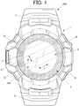
- FIG. 1 is a front view of the timepiece as the display apparatus in this embodiment.
- the timepiece 100 in this embodiment includes a case (hereinafter referred to as a "timepiece case 1" in this embodiment).
- the timepiece case 1 is formed of a hard material such as a hard synthetic resin and a metal (ex. titanium and stainless steel (SUS)).
- the material of the timepiece case 1 is not limited to those exemplified herein.
- the timepiece case 1 in this embodiment is formed in a shape of a hollow short column that opens up and down in the thickness direction of the case (front and back in the timepiece).
- Belt attaching parts 11 are provided at the upper and lower ends of the timepiece case 1 in FIG.1 , that is, at the ends around positions of 12 o'clock and 6 o'clock. To the belt attaching parts 11, a timepiece belt(s) is attached.
- the timepiece 100 includes an operation button(s) 12 on the lateral side or the like of the timepiece case 1.
- an operation button(s) 12 on the lateral side or the like of the timepiece case 1.
- four push buttons, two at the left and right ends respectively, are disposed as the operation buttons 12 in the timepiece case 1.
- a windshield member 3 with light transparency that is made of transparent glass or the like is formed at the opening on the front surface side of the timepiece case 1 to cover the opening.
- a back cover not shown in the drawings is formed on the back surface of the timepiece case 1 to close the opening.
- the outer periphery on the lower surface (the surface disposed inside the timepiece case 1) side of the windshield member 3 is a ring-shaped decorative part 31 in this embodiment.
- the decorative part 31 is decorated all over with pattern, coloring, and the like by a method that does not block light transparency and provided with characters, symbols, scales, and the like such as various kinds of logos.
- the decorative part 31 has a function as a blindfold that covers a connecting part of the outer periphery of the display 4, the solar panel 5, and the like housed in the timepiece case 1 so as not to be seen from the outside.
- the method of forming the decorative part 31 is not particularly limited, and, for example, printing, vapor deposition, or the like is performed on the lower surface of the windshield member 3.
- the decorative part 31 is not limited to one that is provided by printing or the like on the lower surface of the windshield member 3.
- an exterior member, a bezel, or the like on the lower or upper side of the windshield member 3 may be a decorative part that functions as blindfold of the outer periphery of the display or the like.
- the decorative part has light transparency also in that case.
- a module to operate each component of the timepiece 100 as the display apparatus (a timepiece module including a time measurement circuit as a timing unit to execute clock processing) is housed inside the timepiece case 1 in this embodiment.
- a display 4 including a liquid crystal panel (not shown in the drawings) is disposed between the module and the windshield member 3 over the module (on the surface side, the view side of the timepiece) .
- the display elements of the liquid crystal panel or the like may be of a reflective type or a transparent type.
- the configuration of the display 4 is not particularly limited, and may include an analog display method including a clock face, hands, and the like.
- the display 4 may also include both a digital display method including a liquid crystal panel or the like and an analog display method.
- the outer periphery of the display 4 (peripheral edge or the like) is covered with the decorative part 31 and not seen from the outside.
- the area surrounded by the decorative part 31 is a visible area VAr that is visible from the outside in the display 4.
- a solar panel 5 is disposed between the display 4 and the windshield member 3.
- the solar panel 5 is formed of multiple cells, as shown in dashed lines in FIG. 1 , and overlaid on the view side of the display 4 (on the surface side of the timepiece 100).
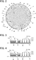
- FIG. 2 is a plan view of a solar panel in the embodiment.
- the solar panel 5 includes a power generation area 51 (including a thin-line power generation area 51a) that functions as a solar cell receiving light to generate power.
- the power generated by the solar panel 5 using photovoltaic power generation is stored in the secondary battery (not shown in the drawings).
- the solar panel 5 in this embodiment includes solar cells C formed in a belt-shape extending therein in the planar direction.
- the solar cells C are arranged in rows in the cell-width direction W perpendicular to the extending direction L.
- the solar cells C are divided from each other by partition areas 53.
- the partition areas 53 are formed in a belt-shape in a width equal to the width of the transparent areas 52 (described later) from an end to the other in the extending direction L.
- the solar panel 5 includes connecting parts 54 that respectively connect the solar cells C with each other electrically in series at respective ends of the solar cells C in the extending direction L.
- the connecting parts 54 are disposed across the partition areas 53 that divide the solar cells C from each other.
- the solar panel 5 is configured integrally by the solar cells C that are connected with each other at the connecting parts 54.
- the connecting parts 54 are disposed outside the visible area VAr and not seen from the outside.
- the solar panel 5 includes two terminals 55.
- One of the terminals 55 is electrically connected to a positive electrode on the base board (not shown in the drawings) of the module, and the other one of the terminals 55 is electrically connected to a negative electrode on the base board.
- the positioning of the terminals 55 is not particularly limited, but they are respectively disposed at the ends of the solar cells C2 and C4 in FIG. 2 , for example.
- the number of the solar cells C of which the solar panel 5 is composed is not particularly limited.
- the solar panel 5 is composed of eight solar cells C (C1 to C8 in FIG. 2 ) that are connected in series, for example.
- the number of the solar cells C that are connected in series is larger, the voltage of the solar panel 5 as a whole is higher.
- the number of the solar cells C of which the solar panel 5 is composed is suitably determined according to the level of the necessary voltage such as the voltage of the secondary battery storing the power generated by the solar panel 5.
- At least part of the solar cells C include a transparent power generation area SAr in which the power generation areas 51 and the transparent areas 52 are alternately disposed to extend in the extending direction L.
- At least part of the solar cells C corresponding to the visible area VAr (described above) that is seen from the outside is configured as the transparent power generation area SAr that extends across the multiple solar cells.
- the power generation areas 51 in the transparent power generation area SAr are disposed at equal intervals.
- some of the power generation areas 51 that are disposed in the transparent power generation area SAr are the thin-line power generation areas 51a formed in a thin-line with a width smaller than that of the transparent area 52.
- the thin-line power generation areas 51a are disposed in the transparent power generation area SAr at intervals. This makes the surface uniformly bright as a whole when the display 4 is viewed from the outside, even with the solar cells C being disposed on the upper side of the display 4, and thus the thin-line power generation areas 51a are prevented from being noticeable. This can realize good visibility of the display 4 and a high-quality appearance.
- the “generation areas 51" used in the embodiments include both the thin-line power generation area 51a and the other power generation areas 51.
- the thinness of the thin-line power generation areas 51a (the length in the cell-width direction W) is not particularly limited, but it is about 10 ⁇ m in a case where the thinness of the transparent areas 52 (the length in the cell-width direction W) is about 70 ⁇ m.
- the solar panel 5 in the transparent power generation areas SAr is more transparent, improving the visibility of the visible area VAr of the display 4.
- the width of the thin-line power generation areas 51a is smaller, the power generation amount is smaller, and the resistance of the movement of electric charges in the solar cell C is higher, deteriorating the power generation efficiency.
- the widths of the thin-line power generation areas 51a and the transparent areas 52 are suitably determined to balance the visibility desired for the visible area VAr of the display 4 (that is, the extent of transparency of the transparent power generation area SAr corresponding to the visible area VAr) and the power generation amount and efficiency desired for the solar panel 5.
- the sizes of the power generation areas 51 of the solar cells C are preferably as equal as possible.
- the sizes of the solar cells C1 and C8 that respectively have the power generation areas 51 almost all over are smaller, and the sizes of the solar cells C4 and C5 that largely correspond to the transparent power generation area SAr and that have more of the thin-line power generation areas 51a are comparatively larger, as shown in FIG. 2 . Accordingly, the sizes of the whole power generation areas 51 including the thin-line power generation areas 51a are adjusted to be equal in each of the solar cells C1 to C8, in this embodiment.
- the power generation amount of the power generation areas 51 is decreased at the part with lower transparency.
- the shapes of the power generation areas 51 outside the transparent power generation area SAr may be changed, for example, so as to equalize the sizes of the power generation areas 51 between the solar cells C.
- the solar cells C may be in a shape tapered at an end, in a shape swelling at an end, or in a curved shape. That is, the overall shape of the solar cells C may not be in a flawless belt-shape or a strip-shape as shown in the drawings of this embodiment.
- the power generation areas 51 outside the part corresponding to the visible area VAr (the power generation areas 51 outside the transparent power generation area SAr) have a smaller size of the transparent areas 52 than the transparent power generation area SAr, and have a higher power generation density compared to the transparent power generation area SAr.
- the power generation areas 51 outside the part corresponding to the visible area VAr look shaded overall.
- the power generation areas 51 with a high power generation density is used on the periphery of the timepiece 100 on the view side corresponding to the decorative part 31. This allows the decorative part 31 to function as a blindfold to cover the periphery or the wiring of the module below the solar panel 5.
- FIG. 3 is a cross-sectional view of the solar panel taken along the line III-III in FIG. 2 .
- the solar panel 5 includes, on the base board 50, the power generation areas 51, the transparent areas 52, and the partition areas 53 to divide the solar cells C from each other.
- the power generation areas 51 has a layered structure.
- a back surface electrode 511 is formed on the base board 50, and a semiconductor layer 512 and a transparent electrode 513 are further layered thereon in the written order.
- a transparent sealing material may be formed on the layered structure to cover the base board 50 all over.
- the transparent areas 52 and the partition areas 53 have the base board 50 only, without the back surface electrode 511, the semiconductor layer 512, or the transparent electrode 513.
- the transparent areas 52 and the partition areas 53 may be formed by areas in which the back surface electrode 511, the semiconductor layer 512, and the transparent electrode 513 are not layered on the base board 50. Alternatively, after the back surface electrode 511, the semiconductor layer 512, and the transparent electrode 513 are layered on the base board 50, those layers may be partly removed to form the transparent areas 52 and the partition areas 53.
- the back surface electrode 511 may be removed by any method. For example, a laser processing may be used.
- the base board 50 is a thin plate with transparency, and may be a flexible film of transparent plastic, for example.
- the material of the base board 50 may be transparent resin, glass, and the like, but is not limited to the examples shown in this embodiment.
- the back surface electrode 511 includes a metal material such as aluminum conductor, for example.
- the material of the back surface electrode 511 is not limited to this example.
- the semiconductor layer 512 is formed of amorphous silicon (a-Si:H), for example.
- a-Si:H amorphous silicon
- a semiconductor of a p-n junction type that is formed by joining p-type and n-type semiconductor materials may be used as the semiconductor layer 512, for example.
- the back surface electrode 511 and the semiconductor layer 512 are layered on the base board 50 by vapor deposition, for example.
- the method of forming the back surface electrode 511 and the semiconductor layer 512 on the base board 50 is not limited to the examples described here.
- the transparent electrode 513 is formed by crystallizing zinc oxide, indium oxide, tin oxide, or the like.
- the material or method of formation of the transparent electrode 513 is not limited to these examples.
- the semiconductor layer 512 does not function as the power generation area 51 unless it is between the back surface electrode 511 and the transparent electrode 513. Thus, as shown in FIG. 4 , the semiconductor layer 512 may be left on the base board 50 in the partition areas 53 (see the partition area 53 on the left side of FIG. 4 ).
- the semiconductor layer 512 left on the base board 50 is not transparent, it is visible from the outside.
- the back surface electrode 511, the semiconductor layer 512, and the transparent electrode 513 need to be all removed even in the partition areas 53 (see the partition area 53 between the thin-line power generation areas 51a on the right side of FIG. 4 ).
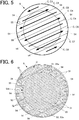
- FIG. 5 is an explanatory drawing schematically showing an example of the moving direction of electric charges in this embodiment.
- the connecting parts 54 to connect the solar cells C with each other are alternately disposed at one of the opposite ends in the extending direction L so that charges are alternately moved from one end to the other in the extending direction L of the solar cells C from the solar cells C1 to C8, as shown in FIG. 5 .
- the arrangement and configuration shown in FIG. 5 is merely an example, and all the connecting parts 54 are not necessarily alternately disposed at one of the opposite ends in the extending direction L.
- the connecting parts 54 need to be alternately disposed at one of the opposite ends in the extending direction L in a case where the solar cells C having at least partly the transparent power generation area SAr extending over the entire cell width are continuously disposed.
- the transparent power generation area SAr extends over the entire cell width W at the central part in the extending direction L of the solar cells C3 to C6 among the solar cells C.
- the connecting parts 54 are alternately disposed at one of the opposite ends in the extending direction L so that charges are not moved back and forth (for the moving distance of charges to be as small as possible) and that charges are moved in one direction. That is effective in regard of reducing electric losses.
- the power generation areas 51 that are not the thin-line power generation areas 51a are continuously disposed from one end to the other in the extending direction L.
- the connecting part 54 to connect the solar cell C1 and the solar cell C2 may be disposed at the ends on the same side in the extending direction L.
- the solar panel 5 is disposed such that the extending direction L of the solar cells C1 to C8 of the solar panel 5 are oblique to the vertical (the up-down direction in FIG. 1 , 12 o'clock to 6 o'clock direction in the analog timepiece) and horizontal (the left-right direction in FIG. 1 , 3 o'clock to 9 o'clock direction in the analog timepiece) directions of the timepiece 100.
- the vertical or horizontal arrangement direction of the display elements of the liquid crystal panel or the like are usually the vertical or horizontal direction of the timepiece 100.
- the extending direction L is the grid arrangement direction of the thin-line power generation areas 51a and the transparent areas 52 in the transparent power generation area SAr in the solar panel 5. In a case where the extending direction L coincides with the arrangement direction of the display elements, moire fringes are likely to be caused, significantly deteriorating the visibility of the display 4.
- the solar panel 5 is disposed at such an angle that the arrangement direction of the display elements of the liquid crystal panel or the like and the extending direction L of the solar cells C are intersecting. This can prevent moire fringes caused due to the correlation with the display 4.
- the angle formed by the arrangement direction of the display elements and the extending direction L of the solar cells C is most preferably 25 degree or 65 degree, and may be 15 degree to 75 degree, to prevent moire fringes.
- the solar panel 5 is disposed in the direction shown in FIG. 1 so that the cell-width direction W, which is the arrangement direction of the solar cells C1 to C8, does not coincide with the horizontal direction of the timepiece 100 (the left-right direction in FIG. 1 , 3 o'clock to 9 o'clock direction in the analog timepiece).
- part of the power generation areas 51 on the opposite side from the finger tips may be covered by the hem of the sleeve depending on the length of the sleeve of the clothe of the user, when the timepiece 100 is put on by the user.
- the power generation amount in part of the solar cells C is extremely decreased, and the power generation efficiency of the solar panel 5 as a whole may be significantly reduced.
- the arrangement direction of the solar cells C1 to C8 and the horizontal direction of the timepiece 100 are intersecting in this embodiment. This can prevent part of the solar cells C from losing the power generation function at all even if the power generation areas 51 of the timepiece 100 are partially covered with the sleeve or the like.
- the power generation amounts of the solar cells C1 to C8 are decreased almost equally, the power generation amount of the solar panel 5 as a whole is decreased.
- the power generation amount can be prevented from decreasing as much as possible.
- the solar panel 5 is mounted on the upper side of the display 4 that is disposed on the view side of the timepiece 100 in this embodiment.
- the solar panel 5 is disposed such that the transparent power generation area SAr corresponds to the visible area VAr of the display 4.
- the transparent power generation area SAr is configured by the thin-line power generation areas 51a and the transparent areas 52 being aligned in the longitudinal direction. This can prevent the visibility of the display 4 from deteriorating even with the solar panel 5 being disposed on the upper side of the display 4 and can maintain the power generation areas 51 on the upper side of the display 4. Accordingly, the power generation amount can be increased in comparison to the case where the power generation areas are disposed on the peripheral part of the display 4 only.
- the solar pane 5 is disposed such that the extending direction L of the solar cells C1 to C8 are oblique to the vertical (the up-down direction in FIG. 1 , 12 o'clock to 6 o'clock direction in the analog timepiece) and horizontal (the left-right direction in FIG. 1 , 3 o'clock to 9 o'clock direction in the analog timepiece) directions of the timepiece 100.
- the display 4 is of a dot-matrix type in which the display elements are arranged in line in a predetermined direction
- the display 4 is configured by the liquid crystal panel or the like and the horizontal or vertical arrangement direction of the display elements is the horizontal or vertical direction of the timepiece 100
- the extending direction L of the solar cells C1 to C8 coincides with a predetermined direction (the vertical or horizontal direction of the timepiece 100)
- overlapping of the transparent power generation amount SAr of the solar panel 5 and the liquid crystal panel or the like may cause moire fringes.
- the electric power is efficiently generated in the power generation areas 51 of the solar cells C1 to C8 in a case where light enters through the windshield member 3.
- the solar cells C are connected by the connecting parts to form the single solar panel 5, and the electric power generated by the solar panel 5 as a whole is stored in the secondary battery. Then, the electric power is supplied from the secondary battery to the components such as the motor of the module, and the timepiece 100 is driven thereby.
- the multiple solar cells C that are formed in a belt-shape and extending in the planar direction are disposed in rows in the cell-width direction W orthogonal to the extending direction L.
- At least the part of the solar cells C corresponding to the visible area VAr that is seen from the outside is formed as the transparent power generation area SAr in which the power generation areas 51 and the transparent areas 52 that transmits light are alternately arranged in the extending direction L.
- the partition areas 53 are formed in a belt-shape having a width equal to that of the transparent areas 52.
- the visibility can be ensured even in the case where the solar panel 5 is disposed on the upper side of the display 4 because the part corresponding to the visible area VAr is the transparent area SAr.
- the part dividing the solar cells C is not noticeable when viewed from the outside, and fringes are not noticeable even in the case where the solar panel 5 is formed of the multiple solar cell C, realizing excellent appearance, because the partition areas 53 have a width equal to that of the transparent areas 52.
- a larger amount of electric power can be generated, because the power generation areas 51 (the thin-line power generation areas 51a in this embodiment) can be disposed on the surface side of the timepiece 100 that can easily receive light.
- the power generation areas 51 in the transparent power generation area SAr are disposed at equal intervals.
- the power generation areas 51 are arranged at equal intervals, and a grid structure is not noticeable when the solar panel 5 is viewed from the outside. As fringes are not noticeable even with the power generation areas 51 being overlaid on the visible area VAr, the appearance can be good.
- the part outside the visible area VAr in the solar cells C is in the power generation areas 51.
- the power generation areas 51 disposed in the transparent power generation area SAr are the thin-line power generation areas 51a that are thinner in width than the transparent areas 52.
- the visibility of the display 4 is not deteriorated, and the appearance can be improved.
- the width of the partition areas 53 are narrower than that of the transparent area 52 at the part outside the visible area VAr.
- the power generation amount can be increased by increase of the size of the power generation areas 51 at the part that is not seen from the outside and does not affect the appearance. In that way, good appearance and excellent power generation capacity can be both obtained.
- the solar panel 5 in this embodiment is used for the timepiece 100 as the display apparatus, the visibility of the display 4 can be ensured and the power generation efficiency of the solar panel 5 can be improved.
- the timepiece 100 (display apparatus) on which the time and various kinds of functions are displayed with good visibility can be realized, and a sufficient amount of electric power can be generated by the solar panel 5 even in a case where the timepiece 100 includes a function unit requiring a lot of electric power.
- the solar panel 5 is overlaid on the view side of the display 4, and the transparent power generation area SAr is disposed at the part corresponding to the visible area VAr that is seen from the outside on the display 4.
- the visibility is not deteriorated even in the case where a larger amount of electric power is generated by the solar panel 5, and the timepiece 100 (display apparatus) in which the display 4 is clearly visible can be realized.
- the partition areas 53 that divide the solar cells C from each other are formed in the width of the transparent areas 52 from one end to the other in the extending direction L of the solar cells C, as shown in FIG. 2 .
- the shape or the like of the partition areas 53 are not limited to this example.
- the partition areas 53 may be reduced in width and be made into narrow partition areas 53a.
- the width of the part of the partition areas 53 outside the transparent power generation area SAr does not need to be the same as the width of the part inside the transparent power generation area SAr, because the part outside the transparent power generation area SAr is not seen from the outside and does not affect the appearance.
- the partition areas 53 is made into the thin partition areas 53a, the size of the power generation areas 51 is increased, and a larger amount of electric power can be generated.
- the part of the solar cells C that corresponds to the central part of the solar panel 5 only is the transparent power generation area SAr.
- the range of the transparent power generation area SAr is not limited to this example.
- the whole of the solar cells C1 to C8 may be the transparent power generation area SAr.
- the transparent power generation area SAr corresponding to the visible area VAr needs to be made wider so that the visibility of the display 4 is secured.
- the whole parts from one end to the other in the extending direction L are the thin-line power generation areas 51a, and the electric resistance value in movement of charges is even higher.
- the connecting parts 54 that connect the solar cells C with each other are alternately disposed at one of the opposite ends in the extending direction L so that charges are alternately moved from one end to the other, from the solar cell C1 to the solar cell C8, in the extending direction L of the solar cells C, and are prevented from being moved back and forth.
- the moving distance of charges can be as short as possible, and electric losses due to increase in the electric resistance value when charges pass through are reduced.
- the power generation efficiency can be kept high.
- the transparent areas 52 may also be the partition areas 53.
- a half of of a partition area 53 belongs to one solar cell C (for example, the solar cell C1) and the other half to the adjoining solar cell C (for example, the solar cell C2).
- the shapes of the solar panel and the solar cells thereof are not limited to circles in the embodiments described above.
- they may be oval, or polygonal as in the solar panel 8 in FIG. 8 , which is octagonal.
- the solar panel 8 is composed of six solar cells C1 to C6 as shown in FIG.8 , for example.
- the number of the solar cells C of which the polygonal solar panel 8 is composed is not limited to this example.
- the part of the display 4 corresponding to the visible area VAr is the transparent power generation area SAr.
- the solar cells C1 to C6 are each divided by the partition areas 53 (including the thin partition areas 53a) such that each of the power generation areas 51 (including the thin-line power generation areas 51a) has an almost equal size.
- the solar panel can be in any shape
- the solar panel according to the present invention can be applied for the timepiece 100 (display apparatus) having the display 4 in various shapes.
- the solar panel 5 is incorporated in the timepiece 100 in this embodiment, as an example. However, the solar panel 5 can be incorporated in any kinds of apparatuses.
- the solar panel 5 can be widely incorporated in display apparatuses that are driven by electric power generated by the solar panel 5, for example, in a biological information display device such as a pedometer, a heartbeat meter, or a pulse meter, a display device that displays various kinds of information such as moving distance, moving pace information, altitude information, barometric pressure information, and the like.
- a biological information display device such as a pedometer, a heartbeat meter, or a pulse meter
- a display device that displays various kinds of information such as moving distance, moving pace information, altitude information, barometric pressure information, and the like.
Landscapes
- Physics & Mathematics (AREA)
- General Physics & Mathematics (AREA)
- Engineering & Computer Science (AREA)
- Power Engineering (AREA)
- Nonlinear Science (AREA)
- Mathematical Physics (AREA)
- Chemical & Material Sciences (AREA)
- Crystallography & Structural Chemistry (AREA)
- Optics & Photonics (AREA)
- Electric Clocks (AREA)
- Electromechanical Clocks (AREA)
Abstract
Description
- The technical field relates to a solar panel, a display apparatus, and a timepiece.
- Display apparatuses with a solar panel that receives light to generate electric power, such as timepieces, have been widely known in the art. Such timepieces generate electric power with a solar panel to charge their secondary battery, and this enables a long-time use without changing a battery.
- For example, with a solar panel, a wrist watch or the like can be convenient timepiece that does not require changing its battery.
- However, in order to stably charge a secondary battery, it is necessary to take a measure since a single solar cell generates low voltage. For example, it is necessary to intervene a step-up converter circuit or connect a plurality of small-divided solar cells connected in series to develop a high-voltage solar panel.
- In this regard, intervening a step-up converter circuit results in a large electric loss caused by the step-up converter itself. To avoid this, the technique of connecting a plurality of solar cells in series has been mostly used to obtain efficient solar panels.
- When a solar panel is used as a battery to drive a display device of a timepiece or the like, it is necessary to secure as large a power generating area as possible at a part that is likely to receive light such as a part where a display is disposed, so that the solar panel can generate a large amount of electric power.
- However, the power generation area is composed of a metal electrode, a semiconductor layer, a transparent electrode, and the like formed of a conductive material such as an aluminum conductor.
- Thus, for example, when the power generation area is disposed to cover the display on the upper side, the display is shaded and the visibility is deteriorated. The appearance of the display apparatus then gets less attractive.
- In this regard, for example,
JP 2001-267604 A JP 2001-267604 A - According to the invention disclosed in
JP 2001-267604 A - However, in a case where a solar panel including multiple solar cells is overlaid on the display area, areas where the solar cells are divided may be noticeable.
- In the case where the solar panel is overlaid on the visible area such as a display, as in
JP 2001-267604 A - The present invention is a solar panel that does not deteriorate visibility and good appearance of a display even if it is overlaid on the visible area, and a display apparatus and a timepiece that include the said solar panel.
- A solar panel reflecting one embodiment includes:
- a plurality of solar cells each of which is formed in a belt-shape extending in a predetermined direction on a plate-shaped surface and which is disposed in rows in a cell-width direction perpendicular to an extending direction of the plurality of solar cells; and
- a partition area that divides the plurality of solar cells from each other;
- wherein the plurality of solar cells has, across at least two of the plurality of solar cells, a transparent power generation area which corresponds at least to a visible area seen from an outside and in which a power generation area and a transparent area that transmits light are alternately disposed and extend in the extending direction,
- wherein in the transparent power generation area, the partition area is formed in a belt-shape having a width equal to a width of the transparent area.
-
-
FIG. 1 is a front view of a timepiece in an embodiment. -
FIG. 2 is a plan view of a solar panel in the embodiment. -
FIG. 3 is a cross-sectional view of the solar panel taken along a line III-III inFIG. 2 . -
FIG. 4 is a cross-sectional view of a variation ofFIG. 3 . -
FIG. 5 is an explanatory drawing of an example of the moving direction of electric charges in the solar panel shown inFIG. 2 . -
FIG. 6 is a plan view of a variation of the solar panel. -
FIG. 7 is a plan view of a variation of the solar panel. -
FIG. 8 is a plan view of a variation of the solar panel. - An embodiment of a solar panel and a timepiece as a display apparatus using the solar panel is described with reference to
FIGs. 1 to 5 . -
FIG. 1 is a front view of the timepiece as the display apparatus in this embodiment. - As shown in
FIG. 1 , thetimepiece 100 in this embodiment includes a case (hereinafter referred to as a "timepiece case 1" in this embodiment). Thetimepiece case 1 is formed of a hard material such as a hard synthetic resin and a metal (ex. titanium and stainless steel (SUS)). The material of thetimepiece case 1 is not limited to those exemplified herein. - The
timepiece case 1 in this embodiment is formed in a shape of a hollow short column that opens up and down in the thickness direction of the case (front and back in the timepiece). -
Belt attaching parts 11 are provided at the upper and lower ends of thetimepiece case 1 inFIG.1 , that is, at the ends around positions of 12 o'clock and 6 o'clock. To thebelt attaching parts 11, a timepiece belt(s) is attached. - The
timepiece 100 includes an operation button(s) 12 on the lateral side or the like of thetimepiece case 1. In the example shown inFIG. 1 , four push buttons, two at the left and right ends respectively, are disposed as theoperation buttons 12 in thetimepiece case 1. - A
windshield member 3 with light transparency that is made of transparent glass or the like is formed at the opening on the front surface side of thetimepiece case 1 to cover the opening. - A back cover not shown in the drawings is formed on the back surface of the
timepiece case 1 to close the opening. - The outer periphery on the lower surface (the surface disposed inside the timepiece case 1) side of the
windshield member 3 is a ring-shapeddecorative part 31 in this embodiment. Thedecorative part 31 is decorated all over with pattern, coloring, and the like by a method that does not block light transparency and provided with characters, symbols, scales, and the like such as various kinds of logos. - The
decorative part 31 has a function as a blindfold that covers a connecting part of the outer periphery of thedisplay 4, thesolar panel 5, and the like housed in thetimepiece case 1 so as not to be seen from the outside. - The method of forming the
decorative part 31 is not particularly limited, and, for example, printing, vapor deposition, or the like is performed on the lower surface of thewindshield member 3. - The
decorative part 31 is not limited to one that is provided by printing or the like on the lower surface of thewindshield member 3. For example, as another member beside thewindshield member 3, an exterior member, a bezel, or the like on the lower or upper side of thewindshield member 3 may be a decorative part that functions as blindfold of the outer periphery of the display or the like.
The decorative part has light transparency also in that case. - A module to operate each component of the
timepiece 100 as the display apparatus (a timepiece module including a time measurement circuit as a timing unit to execute clock processing) is housed inside thetimepiece case 1 in this embodiment. - A
display 4 including a liquid crystal panel (not shown in the drawings) is disposed between the module and thewindshield member 3 over the module (on the surface side, the view side of the timepiece) . The display elements of the liquid crystal panel or the like may be of a reflective type or a transparent type. - Though omitted from
FIG. 1 , the time and various kinds of information are displayed on thedisplay 4. - The configuration of the
display 4 is not particularly limited, and may include an analog display method including a clock face, hands, and the like. Thedisplay 4 may also include both a digital display method including a liquid crystal panel or the like and an analog display method. - As described above, the outer periphery of the display 4 (peripheral edge or the like) is covered with the
decorative part 31 and not seen from the outside. - In this embodiment, the area surrounded by the decorative part 31 (the area almost circular in white shown in
FIG. 1 ) is a visible area VAr that is visible from the outside in thedisplay 4. - A
solar panel 5 is disposed between thedisplay 4 and thewindshield member 3. Thesolar panel 5 is formed of multiple cells, as shown in dashed lines inFIG. 1 , and overlaid on the view side of the display 4 (on the surface side of the timepiece 100). -
FIG. 2 is a plan view of a solar panel in the embodiment. - The
solar panel 5 includes a power generation area 51 (including a thin-line power generation area 51a) that functions as a solar cell receiving light to generate power. The power generated by thesolar panel 5 using photovoltaic power generation is stored in the secondary battery (not shown in the drawings). - As shown in
FIG. 2 , thesolar panel 5 in this embodiment includes solar cells C formed in a belt-shape extending therein in the planar direction. The solar cells C are arranged in rows in the cell-width direction W perpendicular to the extending direction L. - The solar cells C are divided from each other by
partition areas 53. In this embodiment, thepartition areas 53 are formed in a belt-shape in a width equal to the width of the transparent areas 52 (described later) from an end to the other in the extending direction L. - The
solar panel 5 includes connectingparts 54 that respectively connect the solar cells C with each other electrically in series at respective ends of the solar cells C in the extending direction L. - The connecting
parts 54 are disposed across thepartition areas 53 that divide the solar cells C from each other. - The
solar panel 5 is configured integrally by the solar cells C that are connected with each other at the connectingparts 54. - In this embodiment, the connecting
parts 54 are disposed outside the visible area VAr and not seen from the outside. - The
solar panel 5 includes twoterminals 55. One of theterminals 55 is electrically connected to a positive electrode on the base board (not shown in the drawings) of the module, and the other one of theterminals 55 is electrically connected to a negative electrode on the base board. - The positioning of the
terminals 55 is not particularly limited, but they are respectively disposed at the ends of the solar cells C2 and C4 inFIG. 2 , for example. - In this embodiment, the number of the solar cells C of which the
solar panel 5 is composed is not particularly limited. InFIG. 2 , thesolar panel 5 is composed of eight solar cells C (C1 to C8 inFIG. 2 ) that are connected in series, for example. - As the number of the solar cells C that are connected in series is larger, the voltage of the
solar panel 5 as a whole is higher. Thus, the number of the solar cells C of which thesolar panel 5 is composed is suitably determined according to the level of the necessary voltage such as the voltage of the secondary battery storing the power generated by thesolar panel 5. - At least part of the solar cells C (the solar cells C1 to C8) include a transparent power generation area SAr in which the
power generation areas 51 and thetransparent areas 52 are alternately disposed to extend in the extending direction L. - In this embodiment, at least part of the solar cells C corresponding to the visible area VAr (described above) that is seen from the outside is configured as the transparent power generation area SAr that extends across the multiple solar cells.
- The
power generation areas 51 in the transparent power generation area SAr are disposed at equal intervals. - Specifically, some of the
power generation areas 51 that are disposed in the transparent power generation area SAr are the thin-line power generation areas 51a formed in a thin-line with a width smaller than that of thetransparent area 52. - The thin-line power generation areas 51a are disposed in the transparent power generation area SAr at intervals. This makes the surface uniformly bright as a whole when the
display 4 is viewed from the outside, even with the solar cells C being disposed on the upper side of thedisplay 4, and thus the thin-line power generation areas 51a are prevented from being noticeable. This can realize good visibility of thedisplay 4 and a high-quality appearance. - The "
generation areas 51" used in the embodiments include both the thin-line power generation area 51a and the otherpower generation areas 51. - The thinness of the thin-line power generation areas 51a (the length in the cell-width direction W) is not particularly limited, but it is about 10 µm in a case where the thinness of the transparent areas 52 (the length in the cell-width direction W) is about 70 µm.
- As the width of the thin-line power generation areas 51a (the length in the cell-width direction W) is smaller (thinner) and the width of the transparent areas 52 (the length in the cell-width direction W) is larger (thicker), the
solar panel 5 in the transparent power generation areas SAr is more transparent, improving the visibility of the visible area VAr of thedisplay 4. In contrast, as the width of the thin-line power generation areas 51a is smaller, the power generation amount is smaller, and the resistance of the movement of electric charges in the solar cell C is higher, deteriorating the power generation efficiency. - Thus, the widths of the thin-line power generation areas 51a and the
transparent areas 52 are suitably determined to balance the visibility desired for the visible area VAr of the display 4 (that is, the extent of transparency of the transparent power generation area SAr corresponding to the visible area VAr) and the power generation amount and efficiency desired for thesolar panel 5. - As the multiple solar cells C are connected in series to form the single
solar panel 5, a gap in the output current value between the solar cells C results in decrease of the current value of thesolar panel 5 in accordance with the current value smallest of the solar cells C. - Thus, in order to improve the power generation efficiency, the sizes of the
power generation areas 51 of the solar cells C are preferably as equal as possible. - The sizes of the solar cells C1 and C8 that respectively have the
power generation areas 51 almost all over are smaller, and the sizes of the solar cells C4 and C5 that largely correspond to the transparent power generation area SAr and that have more of the thin-line power generation areas 51a are comparatively larger, as shown inFIG. 2 . Accordingly, the sizes of the wholepower generation areas 51 including the thin-line power generation areas 51a are adjusted to be equal in each of the solar cells C1 to C8, in this embodiment. - In a case where part of the
power generation areas 51 is covered with a member having low transparency, for example, with a logo made of a metal as part of thedecorative unit 31, the power generation amount of thepower generation areas 51 is decreased at the part with lower transparency. - In a case where the positioning intervals of the thin-line power generation areas 51a in the transparent power generation area SAr are changed so as to resolve that, the appearance and the visibility are affected by noticeable stripes, for example.
- Thus, the shapes of the
power generation areas 51 outside the transparent power generation area SAr (thepower generation areas 51 outside the part corresponding to the visible area VAr) may be changed, for example, so as to equalize the sizes of thepower generation areas 51 between the solar cells C. In that case, the solar cells C may be in a shape tapered at an end, in a shape swelling at an end, or in a curved shape. That is, the overall shape of the solar cells C may not be in a flawless belt-shape or a strip-shape as shown in the drawings of this embodiment. - The
power generation areas 51 outside the part corresponding to the visible area VAr (thepower generation areas 51 outside the transparent power generation area SAr) have a smaller size of thetransparent areas 52 than the transparent power generation area SAr, and have a higher power generation density compared to the transparent power generation area SAr. Thus, thepower generation areas 51 outside the part corresponding to the visible area VAr look shaded overall. - As in this embodiment shown in
FIG. 2 , thepower generation areas 51 with a high power generation density is used on the periphery of thetimepiece 100 on the view side corresponding to thedecorative part 31. This allows thedecorative part 31 to function as a blindfold to cover the periphery or the wiring of the module below thesolar panel 5. -
FIG. 3 is a cross-sectional view of the solar panel taken along the line III-III inFIG. 2 . - As shown in
FIG. 3 , thesolar panel 5 includes, on thebase board 50, thepower generation areas 51, thetransparent areas 52, and thepartition areas 53 to divide the solar cells C from each other. - Among those, the
power generation areas 51 has a layered structure. In thepower generation area 51, aback surface electrode 511 is formed on thebase board 50, and asemiconductor layer 512 and atransparent electrode 513 are further layered thereon in the written order. A transparent sealing material (protection layer) may be formed on the layered structure to cover thebase board 50 all over. - The
transparent areas 52 and thepartition areas 53 have thebase board 50 only, without theback surface electrode 511, thesemiconductor layer 512, or thetransparent electrode 513. - The
transparent areas 52 and thepartition areas 53 may be formed by areas in which theback surface electrode 511, thesemiconductor layer 512, and thetransparent electrode 513 are not layered on thebase board 50. Alternatively, after theback surface electrode 511, thesemiconductor layer 512, and thetransparent electrode 513 are layered on thebase board 50, those layers may be partly removed to form thetransparent areas 52 and thepartition areas 53. Theback surface electrode 511 may be removed by any method. For example, a laser processing may be used. - The
base board 50 is a thin plate with transparency, and may be a flexible film of transparent plastic, for example. The material of thebase board 50 may be transparent resin, glass, and the like, but is not limited to the examples shown in this embodiment. - The
back surface electrode 511 includes a metal material such as aluminum conductor, for example. The material of theback surface electrode 511 is not limited to this example. - The
semiconductor layer 512 is formed of amorphous silicon (a-Si:H), for example. A semiconductor of a p-n junction type that is formed by joining p-type and n-type semiconductor materials may be used as thesemiconductor layer 512, for example. - The
back surface electrode 511 and thesemiconductor layer 512 are layered on thebase board 50 by vapor deposition, for example. The method of forming theback surface electrode 511 and thesemiconductor layer 512 on thebase board 50 is not limited to the examples described here. - The
transparent electrode 513 is formed by crystallizing zinc oxide, indium oxide, tin oxide, or the like. The material or method of formation of thetransparent electrode 513 is not limited to these examples. - The
semiconductor layer 512 does not function as thepower generation area 51 unless it is between theback surface electrode 511 and thetransparent electrode 513. Thus, as shown inFIG. 4 , thesemiconductor layer 512 may be left on thebase board 50 in the partition areas 53 (see thepartition area 53 on the left side ofFIG. 4 ). - In a case where the
semiconductor layer 512 left on thebase board 50 is not transparent, it is visible from the outside. - Thus, in that case, in the transparent power generation area SAr, the
back surface electrode 511, thesemiconductor layer 512, and thetransparent electrode 513 need to be all removed even in the partition areas 53 (see thepartition area 53 between the thin-line power generation areas 51a on the right side ofFIG. 4 ). -
FIG. 5 is an explanatory drawing schematically showing an example of the moving direction of electric charges in this embodiment. - In this embodiment, the connecting
parts 54 to connect the solar cells C with each other are alternately disposed at one of the opposite ends in the extending direction L so that charges are alternately moved from one end to the other in the extending direction L of the solar cells C from the solar cells C1 to C8, as shown inFIG. 5 . - The arrangement and configuration shown in
FIG. 5 is merely an example, and all the connectingparts 54 are not necessarily alternately disposed at one of the opposite ends in the extending direction L.The connecting parts 54 need to be alternately disposed at one of the opposite ends in the extending direction L in a case where the solar cells C having at least partly the transparent power generation area SAr extending over the entire cell width are continuously disposed. - For example, in this embodiment, the transparent power generation area SAr extends over the entire cell width W at the central part in the extending direction L of the solar cells C3 to C6 among the solar cells C.
- This causes the
power generation areas 51 outside the transparent power generation area SAr to be separated at the opposite ends of the solar cells C. - In the solar cells C3 to C6 as described above, electric charges that are generated in the
power generation areas 51 including the thin-line power generation areas 51a and moved along the extending direction L necessarily pass through the thin-line power generation areas 51a. In thesolar panel 5, the moving path of electric charges is necessarily narrow in a case where thepower generation areas 51 are thin lines, because thesolar panel 5 is also thin in the thickness direction. When electric charges that are generated in thepower generation areas 51 pass through, the electric resistance value is larger than in thepower generation areas 51 that are not thin lines, which results in electric losses. - Thus, the connecting
parts 54 are alternately disposed at one of the opposite ends in the extending direction L so that charges are not moved back and forth (for the moving distance of charges to be as small as possible) and that charges are moved in one direction. That is effective in regard of reducing electric losses. - In contrast, in the solar cells C1, C2, C7, and C8, the
power generation areas 51 that are not the thin-line power generation areas 51a (thepower generation areas 51 that are adequately wide in the cell-width direction W) are continuously disposed from one end to the other in the extending direction L. - Accordingly, in the solar cells C1, C2, C7, and C8, large electric losses due to resistance are not caused in a case where electric charges that are generated in the
power generation areas 51 including the thin-line power generation areas 51a are moved in the extending direction L. - Thus, the connecting
part 54 to connect the solar cell C1 and the solar cell C2, the connectingpart 54 to connect the solar cell C2 and the solar cell C3, the connectingpart 54 to connect the solar cell C6 and the solar cell C7, and the connectingpart 54 to connect the solar cell C7 and the solar cell C8 may be disposed at the ends on the same side in the extending direction L. - In this embodiment, as shown in
FIG. 1 , thesolar panel 5 is disposed such that the extending direction L of the solar cells C1 to C8 of thesolar panel 5 are oblique to the vertical (the up-down direction inFIG. 1 , 12 o'clock to 6 o'clock direction in the analog timepiece) and horizontal (the left-right direction inFIG. 1 ,3 o'clock to 9 o'clock direction in the analog timepiece) directions of thetimepiece 100. - As shown in this embodiment, in a case where the
display 4 of thetimepiece 100 as the display apparatus is a digital type display including a liquid crystal panel or the like, the vertical or horizontal arrangement direction of the display elements of the liquid crystal panel or the like are usually the vertical or horizontal direction of thetimepiece 100. The extending direction L is the grid arrangement direction of the thin-line power generation areas 51a and thetransparent areas 52 in the transparent power generation area SAr in thesolar panel 5. In a case where the extending direction L coincides with the arrangement direction of the display elements, moire fringes are likely to be caused, significantly deteriorating the visibility of thedisplay 4. - To avoid this, the
solar panel 5 is disposed at such an angle that the arrangement direction of the display elements of the liquid crystal panel or the like and the extending direction L of the solar cells C are intersecting. This can prevent moire fringes caused due to the correlation with thedisplay 4. Specifically, the angle formed by the arrangement direction of the display elements and the extending direction L of the solar cells C is most preferably 25 degree or 65 degree, and may be 15 degree to 75 degree, to prevent moire fringes. - In this embodiment, the
solar panel 5 is disposed in the direction shown inFIG. 1 so that the cell-width direction W, which is the arrangement direction of the solar cells C1 to C8, does not coincide with the horizontal direction of the timepiece 100 (the left-right direction inFIG. 1 ,3 o'clock to 9 o'clock direction in the analog timepiece). - In a case where the
timepiece 100 is a wristwatch as shown inFIG. 1 , part of thepower generation areas 51 on the opposite side from the finger tips may be covered by the hem of the sleeve depending on the length of the sleeve of the clothe of the user, when thetimepiece 100 is put on by the user. In a case where the arrangement direction of the solar cells C1 to C8 coincides with the horizontal direction of thetimepiece 100 here, the power generation amount in part of the solar cells C is extremely decreased, and the power generation efficiency of thesolar panel 5 as a whole may be significantly reduced. - In contrast, the arrangement direction of the solar cells C1 to C8 and the horizontal direction of the
timepiece 100 are intersecting in this embodiment. This can prevent part of the solar cells C from losing the power generation function at all even if thepower generation areas 51 of thetimepiece 100 are partially covered with the sleeve or the like. - In a case where, part of the solar cells C being covered with the sleeve or the like, the power generation amounts of the solar cells C1 to C8 are decreased almost equally, the power generation amount of the
solar panel 5 as a whole is decreased. However, compared to the case where part of the power generation amount of the solar cells C are extremely decreased, the power generation amount can be prevented from decreasing as much as possible. - Next, the actions of the
solar panel 5 and thetimepiece 100 as the display apparatus including thesolar panel 5 in this embodiment are described. - The
solar panel 5 is mounted on the upper side of thedisplay 4 that is disposed on the view side of thetimepiece 100 in this embodiment. Thesolar panel 5 is disposed such that the transparent power generation area SAr corresponds to the visible area VAr of thedisplay 4. - The transparent power generation area SAr is configured by the thin-line power generation areas 51a and the
transparent areas 52 being aligned in the longitudinal direction. This can prevent the visibility of thedisplay 4 from deteriorating even with thesolar panel 5 being disposed on the upper side of thedisplay 4 and can maintain thepower generation areas 51 on the upper side of thedisplay 4. Accordingly, the power generation amount can be increased in comparison to the case where the power generation areas are disposed on the peripheral part of thedisplay 4 only. - The
solar pane 5 is disposed such that the extending direction L of the solar cells C1 to C8 are oblique to the vertical (the up-down direction inFIG. 1 , 12 o'clock to 6 o'clock direction in the analog timepiece) and horizontal (the left-right direction inFIG. 1 ,3 o'clock to 9 o'clock direction in the analog timepiece) directions of thetimepiece 100. - In a case where the
display 4 is of a dot-matrix type in which the display elements are arranged in line in a predetermined direction, for example, in a case where thedisplay 4 is configured by the liquid crystal panel or the like and the horizontal or vertical arrangement direction of the display elements is the horizontal or vertical direction of thetimepiece 100, and where the extending direction L of the solar cells C1 to C8 coincides with a predetermined direction (the vertical or horizontal direction of the timepiece 100), overlapping of the transparent power generation amount SAr of thesolar panel 5 and the liquid crystal panel or the like may cause moire fringes. - In this regard, as the extending direction L of the solar cells C1 to C8 is oblique to the predetermined direction at a predetermined angle, moire fringes caused by overlapping of the transparent power generation area SAr of the
solar panel 5 and the liquid crystal panel or the like can be suppressed. - As the
solar panel 5 is disposed on the view side of thetimepiece 100, which is the upper side of the display as well, the electric power is efficiently generated in thepower generation areas 51 of the solar cells C1 to C8 in a case where light enters through thewindshield member 3. The solar cells C are connected by the connecting parts to form the singlesolar panel 5, and the electric power generated by thesolar panel 5 as a whole is stored in the secondary battery. Then, the electric power is supplied from the secondary battery to the components such as the motor of the module, and thetimepiece 100 is driven thereby. - As described above, according to this embodiment, the multiple solar cells C that are formed in a belt-shape and extending in the planar direction are disposed in rows in the cell-width direction W orthogonal to the extending direction L. At least the part of the solar cells C corresponding to the visible area VAr that is seen from the outside is formed as the transparent power generation area SAr in which the
power generation areas 51 and thetransparent areas 52 that transmits light are alternately arranged in the extending direction L. Thepartition areas 53 are formed in a belt-shape having a width equal to that of thetransparent areas 52. - As described above, the visibility can be ensured even in the case where the
solar panel 5 is disposed on the upper side of thedisplay 4 because the part corresponding to the visible area VAr is the transparent area SAr. - The part dividing the solar cells C is not noticeable when viewed from the outside, and fringes are not noticeable even in the case where the
solar panel 5 is formed of the multiple solar cell C, realizing excellent appearance, because thepartition areas 53 have a width equal to that of thetransparent areas 52. - A larger amount of electric power can be generated, because the power generation areas 51 (the thin-line power generation areas 51a in this embodiment) can be disposed on the surface side of the
timepiece 100 that can easily receive light. - According to this embodiment, the
power generation areas 51 in the transparent power generation area SAr are disposed at equal intervals. - As the
power generation areas 51 are arranged at equal intervals, and a grid structure is not noticeable when thesolar panel 5 is viewed from the outside. As fringes are not noticeable even with thepower generation areas 51 being overlaid on the visible area VAr, the appearance can be good. - According to this embodiment, the part outside the visible area VAr in the solar cells C is in the
power generation areas 51. - Thus, a larger amount of electric power can be generated at the part that is not seen from the outside and does not affect the appearance, and good appearance and excellent power generation capacity can be both obtained.
- According to this embodiment, the
power generation areas 51 disposed in the transparent power generation area SAr are the thin-line power generation areas 51a that are thinner in width than thetransparent areas 52. - Thus, even in the case where the
power generation areas 51 are overlaid on the part corresponding to the visible area VAr, the visibility of thedisplay 4 is not deteriorated, and the appearance can be improved. - According to this embodiment, the width of the
partition areas 53 are narrower than that of thetransparent area 52 at the part outside the visible area VAr. - Thus, the power generation amount can be increased by increase of the size of the
power generation areas 51 at the part that is not seen from the outside and does not affect the appearance. In that way, good appearance and excellent power generation capacity can be both obtained. - In the case where the
solar panel 5 in this embodiment is used for thetimepiece 100 as the display apparatus, the visibility of thedisplay 4 can be ensured and the power generation efficiency of thesolar panel 5 can be improved. - Thus, the timepiece 100 (display apparatus) on which the time and various kinds of functions are displayed with good visibility can be realized, and a sufficient amount of electric power can be generated by the
solar panel 5 even in a case where thetimepiece 100 includes a function unit requiring a lot of electric power. - In the timepiece 100 (display apparatus) including the
solar panel 5 according to this embodiment, thesolar panel 5 is overlaid on the view side of thedisplay 4, and the transparent power generation area SAr is disposed at the part corresponding to the visible area VAr that is seen from the outside on thedisplay 4. - Thus, the visibility is not deteriorated even in the case where a larger amount of electric power is generated by the
solar panel 5, and the timepiece 100 (display apparatus) in which thedisplay 4 is clearly visible can be realized. - Although an embodiment of the present invention is described above, needless to say the present invention is not limited to the embodiment and can be appropriately modified in a variety of aspects without departing from the scope of the present invention.
- For example, in the embodiments described above, the
partition areas 53 that divide the solar cells C from each other are formed in the width of thetransparent areas 52 from one end to the other in the extending direction L of the solar cells C, as shown inFIG. 2 . However, the shape or the like of thepartition areas 53 are not limited to this example. - For example, as in the
solar panel 6 shown inFIG. 6 , the part outside the transparent area SAr in the solar cells C (the part corresponding to the part outside the visible area), thepartition areas 53 may be reduced in width and be made into narrow partition areas 53a. - The width of the part of the
partition areas 53 outside the transparent power generation area SAr does not need to be the same as the width of the part inside the transparent power generation area SAr, because the part outside the transparent power generation area SAr is not seen from the outside and does not affect the appearance. - In that case, as the
partition areas 53 is made into the thin partition areas 53a, the size of thepower generation areas 51 is increased, and a larger amount of electric power can be generated. - In this embodiment, the part of the solar cells C that corresponds to the central part of the
solar panel 5 only is the transparent power generation area SAr. However, the range of the transparent power generation area SAr is not limited to this example. - For example, as in the
solar panel 7 shown inFIG. 7 , the whole of the solar cells C1 to C8 (that is, the entire solar panel 7) may be the transparent power generation area SAr. - For example, in a case where the
decorative part 31 is absent and the visible area VAr of thedisplay 4 is wide, the transparent power generation area SAr corresponding to the visible area VAr needs to be made wider so that the visibility of thedisplay 4 is secured. - In that case, as shown in
FIG. 7 , in the solar cells C1 to C8, the whole parts from one end to the other in the extending direction L are the thin-line power generation areas 51a, and the electric resistance value in movement of charges is even higher. - To avoid this, as in this embodiment, the connecting
parts 54 that connect the solar cells C with each other are alternately disposed at one of the opposite ends in the extending direction L so that charges are alternately moved from one end to the other, from the solar cell C1 to the solar cell C8, in the extending direction L of the solar cells C, and are prevented from being moved back and forth. - As a result, the moving distance of charges can be as short as possible, and electric losses due to increase in the electric resistance value when charges pass through are reduced. The power generation efficiency can be kept high.
- In the case where the whole of the solar cells C1 to C8 (that is, the entire solar panel 7) are the transparent power generation area SAr, the
transparent areas 52 may also be thepartition areas 53. - In that case, as shown in dashed lines in
FIG. 7 , being divided along the extending direction L, a half of of apartition area 53 belongs to one solar cell C (for example, the solar cell C1) and the other half to the adjoining solar cell C (for example, the solar cell C2). - The shapes of the solar panel and the solar cells thereof are not limited to circles in the embodiments described above.
- For example, they may be oval, or polygonal as in the
solar panel 8 inFIG. 8 , which is octagonal. - The
solar panel 8 is composed of six solar cells C1 to C6 as shown inFIG.8 , for example. However, the number of the solar cells C of which the polygonalsolar panel 8 is composed is not limited to this example. - In that case, too, the part of the
display 4 corresponding to the visible area VAr is the transparent power generation area SAr. - The solar cells C1 to C6 are each divided by the partition areas 53 (including the thin partition areas 53a) such that each of the power generation areas 51 (including the thin-line power generation areas 51a) has an almost equal size.
- As the solar panel can be in any shape, the solar panel according to the present invention can be applied for the timepiece 100 (display apparatus) having the
display 4 in various shapes. - The
solar panel 5 is incorporated in thetimepiece 100 in this embodiment, as an example. However, thesolar panel 5 can be incorporated in any kinds of apparatuses. - The
solar panel 5 can be widely incorporated in display apparatuses that are driven by electric power generated by thesolar panel 5, for example, in a biological information display device such as a pedometer, a heartbeat meter, or a pulse meter, a display device that displays various kinds of information such as moving distance, moving pace information, altitude information, barometric pressure information, and the like. - Although one or more embodiments have been described, the scope of the present invention is not limited to the embodiments and includes the scope of claims below and the scope of their equivalents.
Claims (11)
- A solar panel (5) comprising:a plurality of solar cells (C) each of which is formed in a belt-shape extending in a predetermined direction on a plate-shaped surface and which is disposed in rows in a cell-width direction perpendicular to an extending direction of the plurality of solar cells; anda partition area (53) that divides the plurality of solar cells from each other;wherein the plurality of solar cells has, across at least two of the plurality of solar cells, a transparent power generation area (SAr) which corresponds at least to a visible area (VAr) seen from an outside and in which a power generation area (51) and a transparent area (52) that transmits light are alternately disposed and extend in the extending direction,wherein in the transparent power generation area, the partition area is formed in a belt-shape having a width equal to a width of the transparent area.
- The solar panel according to claim 1, wherein in the transparent power generation area, the power generation area is arranged at an equal interval.
- The solar panel according to claim 1 or 2, wherein a part of the plurality of solar cells corresponding to a part outside the visible area is composed of the power generation area.
- The solar panel according to any one of claims 1 to 3, wherein in the transparent power generation area, the power generation area is formed in a shape of a thin line that is narrower than the transparent area.
- The solar panel according to any one of claims 1 to 4, wherein in a part of the plurality of solar cells corresponding to a part outside the visible area, the partition area has a width narrower than the width of the transparent area.
- A display apparatus (100) comprising:the solar panel according to any one of claims 1 to 5; anda display (4).
- The display apparatus according to claim 6,
wherein the display is of a dot matrix type in which display elements are arranged in a predetermined arrangement direction,
wherein the extending direction of the plurality of solar cells is oblique to the predetermined arrangement direction at a predetermined angle. - The display apparatus according to claim 6 or 7,
wherein the solar panel is overlaid on a view side of the display,
wherein the transparent power generation area is disposed in a part corresponding to the visible area that is seen from the outside in the display. - A timepiece (100) comprising:the solar panel according to any one of claims 1 to 5;a display (4); anda timing unit that performs clock processing.
- The timepiece according to claim 9,
wherein the display is of a dot matrix type in which display elements are arranged in a predetermined arrangement direction,
wherein the extending direction of the plurality of solar cells is oblique to the predetermined arrangement direction at a predetermined angle. - The timepiece according to claim 9 or 10,
wherein the solar panel is overlaid on a visible side of the display,
wherein the transparent power generation area is disposed in a part corresponding to the visible area that is seen from the outside in the display.
Applications Claiming Priority (1)
| Application Number | Priority Date | Filing Date | Title |
|---|---|---|---|
| JP2019057775A JP6927245B2 (en) | 2019-03-26 | 2019-03-26 | Solar panels, display devices and clocks |
Publications (2)
| Publication Number | Publication Date |
|---|---|
| EP3715962A1 true EP3715962A1 (en) | 2020-09-30 |
| EP3715962B1 EP3715962B1 (en) | 2024-10-30 |
Family
ID=69960396
Family Applications (1)
| Application Number | Title | Priority Date | Filing Date |
|---|---|---|---|
| EP20165199.9A Active EP3715962B1 (en) | 2019-03-26 | 2020-03-24 | Solar panel for timepieces |
Country Status (4)
| Country | Link |
|---|---|
| US (1) | US11675315B2 (en) |
| EP (1) | EP3715962B1 (en) |
| JP (2) | JP6927245B2 (en) |
| CN (1) | CN111769169B (en) |
Cited By (1)
| Publication number | Priority date | Publication date | Assignee | Title |
|---|---|---|---|---|
| WO2023030703A1 (en) * | 2021-08-30 | 2023-03-09 | The Swatch Group Research And Development Ltd | Electronic device comprising a solar cell and process for manufacturing said solar cell |
Families Citing this family (3)
| Publication number | Priority date | Publication date | Assignee | Title |
|---|---|---|---|---|
| JP6891914B2 (en) * | 2019-03-26 | 2021-06-18 | カシオ計算機株式会社 | Solar panels, display devices and clocks |
| US11841686B2 (en) * | 2020-11-09 | 2023-12-12 | Garmin Switzerland Gmbh | Integrated energy-collecting display module with core out |
| TWI777786B (en) * | 2021-09-27 | 2022-09-11 | 凌巨科技股份有限公司 | Solar cell with transparent type |
Citations (3)
| Publication number | Priority date | Publication date | Assignee | Title |
|---|---|---|---|---|
| EP1126337A1 (en) * | 1998-11-26 | 2001-08-22 | Citizen Watch Co. Ltd. | Timepiece |
| JP2001267604A (en) | 2000-03-21 | 2001-09-28 | Citizen Watch Co Ltd | Electronic device with solar cell and solar cell module |
| EP2109149A1 (en) * | 2007-01-25 | 2009-10-14 | Sharp Kabushiki Kaisha | Solar battery cell, solar battery array, solar battery module and method for manufacturing solar battery array |
Family Cites Families (11)
| Publication number | Priority date | Publication date | Assignee | Title |
|---|---|---|---|---|
| JPH11242086A (en) * | 1997-08-04 | 1999-09-07 | Seiko Epson Corp | Display device and electronic timepiece using the same |
| JP4607277B2 (en) * | 2000-03-21 | 2011-01-05 | シチズンホールディングス株式会社 | Electronics |
| WO2001071434A1 (en) * | 2000-03-21 | 2001-09-27 | Citizen Watch Co., Ltd. | Electronic unit |
| JP4397092B2 (en) * | 2000-03-21 | 2010-01-13 | シチズンホールディングス株式会社 | Electronic device and solar cell module |
| GB2446838A (en) * | 2007-02-20 | 2008-08-27 | David John Ruchat | Photovoltaic device and manufacturing method |
| JP5087959B2 (en) * | 2007-03-15 | 2012-12-05 | カシオ計算機株式会社 | Display control device, electronic wristwatch, and display control program |
| WO2012060246A1 (en) * | 2010-11-02 | 2012-05-10 | シャープ株式会社 | Solar battery-equipped display device and electronic equipment |
| JP2013048222A (en) * | 2011-07-22 | 2013-03-07 | Asahi Glass Co Ltd | Solar cell module |
| JP2016066654A (en) * | 2014-09-24 | 2016-04-28 | 株式会社Ena | Solar panel |
| JP6740574B2 (en) * | 2015-07-22 | 2020-08-19 | セイコーエプソン株式会社 | clock |
| US20180261704A1 (en) * | 2017-03-13 | 2018-09-13 | Intel Corporation | Monolithic integration of dissimilar photovoltaic layers in wearable devices |
-
2019
- 2019-03-26 JP JP2019057775A patent/JP6927245B2/en active Active
-
2020
- 2020-03-11 CN CN202010167742.9A patent/CN111769169B/en active Active
- 2020-03-12 US US16/816,818 patent/US11675315B2/en active Active
- 2020-03-24 EP EP20165199.9A patent/EP3715962B1/en active Active
-
2021
- 2021-08-02 JP JP2021126388A patent/JP2021167847A/en active Pending
Patent Citations (3)
| Publication number | Priority date | Publication date | Assignee | Title |
|---|---|---|---|---|
| EP1126337A1 (en) * | 1998-11-26 | 2001-08-22 | Citizen Watch Co. Ltd. | Timepiece |
| JP2001267604A (en) | 2000-03-21 | 2001-09-28 | Citizen Watch Co Ltd | Electronic device with solar cell and solar cell module |
| EP2109149A1 (en) * | 2007-01-25 | 2009-10-14 | Sharp Kabushiki Kaisha | Solar battery cell, solar battery array, solar battery module and method for manufacturing solar battery array |
Cited By (1)
| Publication number | Priority date | Publication date | Assignee | Title |
|---|---|---|---|---|
| WO2023030703A1 (en) * | 2021-08-30 | 2023-03-09 | The Swatch Group Research And Development Ltd | Electronic device comprising a solar cell and process for manufacturing said solar cell |
Also Published As
| Publication number | Publication date |
|---|---|
| JP2020159788A (en) | 2020-10-01 |
| CN111769169A (en) | 2020-10-13 |
| EP3715962B1 (en) | 2024-10-30 |
| JP6927245B2 (en) | 2021-08-25 |
| CN111769169B (en) | 2024-12-17 |
| JP2021167847A (en) | 2021-10-21 |
| US20200310356A1 (en) | 2020-10-01 |
| US11675315B2 (en) | 2023-06-13 |
Similar Documents
| Publication | Publication Date | Title |
|---|---|---|
| EP3715962B1 (en) | Solar panel for timepieces | |
| US20250110449A1 (en) | Solar panel, display device, and timepiece | |
| CN105531633B (en) | Solar panels and the clock and watch including solar panels | |
| WO2001071434A1 (en) | Electronic unit | |
| EP3715961B1 (en) | Display device comprising a solar panel | |
| US20170023915A1 (en) | Timepiece | |
| EP3872579A1 (en) | Wearable electronic device | |
| US11594649B2 (en) | Photoelectric converter, photoelectric conversion module, and electronic instrument | |
| US12349471B2 (en) | Solar panel, electronic instrument, and electronic timepiece | |
| JP7078024B2 (en) | Solar panels, electronic devices and electronic clocks | |
| JP4397092B2 (en) | Electronic device and solar cell module | |
| JP4397091B2 (en) | Electronic device and solar cell module | |
| JP2020159706A (en) | Electronic timepiece and solar battery module | |
| JP2000111670A (en) | Wristwatch | |
| JP2020204619A (en) | Solar panel, display device, and watch | |
| JP2015129685A (en) | Electronic timepiece with solar battery |
Legal Events
| Date | Code | Title | Description |
|---|---|---|---|
| PUAI | Public reference made under article 153(3) epc to a published international application that has entered the european phase |
Free format text: ORIGINAL CODE: 0009012 |
|
| STAA | Information on the status of an ep patent application or granted ep patent |
Free format text: STATUS: REQUEST FOR EXAMINATION WAS MADE |
|
| 17P | Request for examination filed |
Effective date: 20200324 |
|
| AK | Designated contracting states |
Kind code of ref document: A1 Designated state(s): AL AT BE BG CH CY CZ DE DK EE ES FI FR GB GR HR HU IE IS IT LI LT LU LV MC MK MT NL NO PL PT RO RS SE SI SK SM TR |
|
| AX | Request for extension of the european patent |
Extension state: BA ME |
|
| RIN1 | Information on inventor provided before grant (corrected) |
Inventor name: SAITO, YUTA |
|
| STAA | Information on the status of an ep patent application or granted ep patent |
Free format text: STATUS: EXAMINATION IS IN PROGRESS |
|
| 17Q | First examination report despatched |
Effective date: 20220713 |
|
| GRAP | Despatch of communication of intention to grant a patent |
Free format text: ORIGINAL CODE: EPIDOSNIGR1 |
|
| STAA | Information on the status of an ep patent application or granted ep patent |
Free format text: STATUS: GRANT OF PATENT IS INTENDED |
|
| INTG | Intention to grant announced |
Effective date: 20240617 |
|
| GRAS | Grant fee paid |
Free format text: ORIGINAL CODE: EPIDOSNIGR3 |
|
| GRAA | (expected) grant |
Free format text: ORIGINAL CODE: 0009210 |
|
| STAA | Information on the status of an ep patent application or granted ep patent |
Free format text: STATUS: THE PATENT HAS BEEN GRANTED |
|
| AK | Designated contracting states |
Kind code of ref document: B1 Designated state(s): AL AT BE BG CH CY CZ DE DK EE ES FI FR GB GR HR HU IE IS IT LI LT LU LV MC MK MT NL NO PL PT RO RS SE SI SK SM TR |
|
| REG | Reference to a national code |
Ref country code: GB Ref legal event code: FG4D |
|
| REG | Reference to a national code |
Ref country code: CH Ref legal event code: EP |
|
| REG | Reference to a national code |
Ref country code: IE Ref legal event code: FG4D |
|
| REG | Reference to a national code |
Ref country code: DE Ref legal event code: R096 Ref document number: 602020040146 Country of ref document: DE |
|
| REG | Reference to a national code |
Ref country code: LT Ref legal event code: MG9D |
|
| REG | Reference to a national code |
Ref country code: NL Ref legal event code: MP Effective date: 20241030 |
|
| PG25 | Lapsed in a contracting state [announced via postgrant information from national office to epo] |
Ref country code: IS Free format text: LAPSE BECAUSE OF FAILURE TO SUBMIT A TRANSLATION OF THE DESCRIPTION OR TO PAY THE FEE WITHIN THE PRESCRIBED TIME-LIMIT Effective date: 20250228 Ref country code: HR Free format text: LAPSE BECAUSE OF FAILURE TO SUBMIT A TRANSLATION OF THE DESCRIPTION OR TO PAY THE FEE WITHIN THE PRESCRIBED TIME-LIMIT Effective date: 20241030 Ref country code: PT Free format text: LAPSE BECAUSE OF FAILURE TO SUBMIT A TRANSLATION OF THE DESCRIPTION OR TO PAY THE FEE WITHIN THE PRESCRIBED TIME-LIMIT Effective date: 20250228 |
|
| PG25 | Lapsed in a contracting state [announced via postgrant information from national office to epo] |
Ref country code: NL Free format text: LAPSE BECAUSE OF FAILURE TO SUBMIT A TRANSLATION OF THE DESCRIPTION OR TO PAY THE FEE WITHIN THE PRESCRIBED TIME-LIMIT Effective date: 20241030 Ref country code: FI Free format text: LAPSE BECAUSE OF FAILURE TO SUBMIT A TRANSLATION OF THE DESCRIPTION OR TO PAY THE FEE WITHIN THE PRESCRIBED TIME-LIMIT Effective date: 20241030 |
|
| REG | Reference to a national code |
Ref country code: AT Ref legal event code: MK05 Ref document number: 1737490 Country of ref document: AT Kind code of ref document: T Effective date: 20241030 |
|
| PG25 | Lapsed in a contracting state [announced via postgrant information from national office to epo] |
Ref country code: BG Free format text: LAPSE BECAUSE OF FAILURE TO SUBMIT A TRANSLATION OF THE DESCRIPTION OR TO PAY THE FEE WITHIN THE PRESCRIBED TIME-LIMIT Effective date: 20241030 |
|
| PG25 | Lapsed in a contracting state [announced via postgrant information from national office to epo] |
Ref country code: ES Free format text: LAPSE BECAUSE OF FAILURE TO SUBMIT A TRANSLATION OF THE DESCRIPTION OR TO PAY THE FEE WITHIN THE PRESCRIBED TIME-LIMIT Effective date: 20241030 |
|
| PG25 | Lapsed in a contracting state [announced via postgrant information from national office to epo] |
Ref country code: NO Free format text: LAPSE BECAUSE OF FAILURE TO SUBMIT A TRANSLATION OF THE DESCRIPTION OR TO PAY THE FEE WITHIN THE PRESCRIBED TIME-LIMIT Effective date: 20250130 |
|
| PG25 | Lapsed in a contracting state [announced via postgrant information from national office to epo] |
Ref country code: LV Free format text: LAPSE BECAUSE OF FAILURE TO SUBMIT A TRANSLATION OF THE DESCRIPTION OR TO PAY THE FEE WITHIN THE PRESCRIBED TIME-LIMIT Effective date: 20241030 Ref country code: AT Free format text: LAPSE BECAUSE OF FAILURE TO SUBMIT A TRANSLATION OF THE DESCRIPTION OR TO PAY THE FEE WITHIN THE PRESCRIBED TIME-LIMIT Effective date: 20241030 Ref country code: GR Free format text: LAPSE BECAUSE OF FAILURE TO SUBMIT A TRANSLATION OF THE DESCRIPTION OR TO PAY THE FEE WITHIN THE PRESCRIBED TIME-LIMIT Effective date: 20250131 |
|
| PG25 | Lapsed in a contracting state [announced via postgrant information from national office to epo] |
Ref country code: PL Free format text: LAPSE BECAUSE OF FAILURE TO SUBMIT A TRANSLATION OF THE DESCRIPTION OR TO PAY THE FEE WITHIN THE PRESCRIBED TIME-LIMIT Effective date: 20241030 |
|
| PG25 | Lapsed in a contracting state [announced via postgrant information from national office to epo] |
Ref country code: RS Free format text: LAPSE BECAUSE OF FAILURE TO SUBMIT A TRANSLATION OF THE DESCRIPTION OR TO PAY THE FEE WITHIN THE PRESCRIBED TIME-LIMIT Effective date: 20250130 |
|
| PG25 | Lapsed in a contracting state [announced via postgrant information from national office to epo] |
Ref country code: SM Free format text: LAPSE BECAUSE OF FAILURE TO SUBMIT A TRANSLATION OF THE DESCRIPTION OR TO PAY THE FEE WITHIN THE PRESCRIBED TIME-LIMIT Effective date: 20241030 |
|
| PG25 | Lapsed in a contracting state [announced via postgrant information from national office to epo] |
Ref country code: DK Free format text: LAPSE BECAUSE OF FAILURE TO SUBMIT A TRANSLATION OF THE DESCRIPTION OR TO PAY THE FEE WITHIN THE PRESCRIBED TIME-LIMIT Effective date: 20241030 |
|
| PG25 | Lapsed in a contracting state [announced via postgrant information from national office to epo] |
Ref country code: EE Free format text: LAPSE BECAUSE OF FAILURE TO SUBMIT A TRANSLATION OF THE DESCRIPTION OR TO PAY THE FEE WITHIN THE PRESCRIBED TIME-LIMIT Effective date: 20241030 |
|
| PG25 | Lapsed in a contracting state [announced via postgrant information from national office to epo] |
Ref country code: RO Free format text: LAPSE BECAUSE OF FAILURE TO SUBMIT A TRANSLATION OF THE DESCRIPTION OR TO PAY THE FEE WITHIN THE PRESCRIBED TIME-LIMIT Effective date: 20241030 |
|
| PG25 | Lapsed in a contracting state [announced via postgrant information from national office to epo] |
Ref country code: SK Free format text: LAPSE BECAUSE OF FAILURE TO SUBMIT A TRANSLATION OF THE DESCRIPTION OR TO PAY THE FEE WITHIN THE PRESCRIBED TIME-LIMIT Effective date: 20241030 |
|
| PG25 | Lapsed in a contracting state [announced via postgrant information from national office to epo] |
Ref country code: CZ Free format text: LAPSE BECAUSE OF FAILURE TO SUBMIT A TRANSLATION OF THE DESCRIPTION OR TO PAY THE FEE WITHIN THE PRESCRIBED TIME-LIMIT Effective date: 20241030 |
|
| PG25 | Lapsed in a contracting state [announced via postgrant information from national office to epo] |
Ref country code: IT Free format text: LAPSE BECAUSE OF FAILURE TO SUBMIT A TRANSLATION OF THE DESCRIPTION OR TO PAY THE FEE WITHIN THE PRESCRIBED TIME-LIMIT Effective date: 20241030 |
|
| REG | Reference to a national code |
Ref country code: DE Ref legal event code: R097 Ref document number: 602020040146 Country of ref document: DE |
|
| PLBE | No opposition filed within time limit |
Free format text: ORIGINAL CODE: 0009261 |
|
| STAA | Information on the status of an ep patent application or granted ep patent |
Free format text: STATUS: NO OPPOSITION FILED WITHIN TIME LIMIT |
|
| PG25 | Lapsed in a contracting state [announced via postgrant information from national office to epo] |
Ref country code: SE Free format text: LAPSE BECAUSE OF FAILURE TO SUBMIT A TRANSLATION OF THE DESCRIPTION OR TO PAY THE FEE WITHIN THE PRESCRIBED TIME-LIMIT Effective date: 20241030 |
|
| 26N | No opposition filed |
Effective date: 20250731 |
|
| PG25 | Lapsed in a contracting state [announced via postgrant information from national office to epo] |
Ref country code: MC Free format text: LAPSE BECAUSE OF FAILURE TO SUBMIT A TRANSLATION OF THE DESCRIPTION OR TO PAY THE FEE WITHIN THE PRESCRIBED TIME-LIMIT Effective date: 20241030 |
|
| REG | Reference to a national code |
Ref country code: CH Ref legal event code: H13 Free format text: ST27 STATUS EVENT CODE: U-0-0-H10-H13 (AS PROVIDED BY THE NATIONAL OFFICE) Effective date: 20251023 |
|
| PG25 | Lapsed in a contracting state [announced via postgrant information from national office to epo] |
Ref country code: LU Free format text: LAPSE BECAUSE OF NON-PAYMENT OF DUE FEES Effective date: 20250324 |
|
| REG | Reference to a national code |
Ref country code: BE Ref legal event code: MM Effective date: 20250331 |
|
| PG25 | Lapsed in a contracting state [announced via postgrant information from national office to epo] |
Ref country code: BE Free format text: LAPSE BECAUSE OF NON-PAYMENT OF DUE FEES Effective date: 20250331 |
|
| PG25 | Lapsed in a contracting state [announced via postgrant information from national office to epo] |
Ref country code: CH Free format text: LAPSE BECAUSE OF NON-PAYMENT OF DUE FEES Effective date: 20250331 |
|
| PG25 | Lapsed in a contracting state [announced via postgrant information from national office to epo] |
Ref country code: IE Free format text: LAPSE BECAUSE OF NON-PAYMENT OF DUE FEES Effective date: 20250324 |
|
| PGFP | Annual fee paid to national office [announced via postgrant information from national office to epo] |
Ref country code: GB Payment date: 20260202 Year of fee payment: 7 |
|
| PGFP | Annual fee paid to national office [announced via postgrant information from national office to epo] |
Ref country code: DE Payment date: 20260128 Year of fee payment: 7 |
|
| PGFP | Annual fee paid to national office [announced via postgrant information from national office to epo] |
Ref country code: FR Payment date: 20260209 Year of fee payment: 7 |