JP6740574B2 - clock - Google Patents
clock Download PDFInfo
- Publication number
- JP6740574B2 JP6740574B2 JP2015144949A JP2015144949A JP6740574B2 JP 6740574 B2 JP6740574 B2 JP 6740574B2 JP 2015144949 A JP2015144949 A JP 2015144949A JP 2015144949 A JP2015144949 A JP 2015144949A JP 6740574 B2 JP6740574 B2 JP 6740574B2
- Authority
- JP
- Japan
- Prior art keywords
- dial
- solar panel
- solar cells
- timepiece
- solar
- Prior art date
- Legal status (The legal status is an assumption and is not a legal conclusion. Google has not performed a legal analysis and makes no representation as to the accuracy of the status listed.)
- Active
Links
Images


Classifications
-
- G—PHYSICS
- G04—HOROLOGY
- G04C—ELECTROMECHANICAL CLOCKS OR WATCHES
- G04C10/00—Arrangements of electric power supplies in time pieces
- G04C10/02—Arrangements of electric power supplies in time pieces the power supply being a radioactive or photovoltaic source
-
- G—PHYSICS
- G04—HOROLOGY
- G04G—ELECTRONIC TIME-PIECES
- G04G17/00—Structural details; Housings
- G04G17/02—Component assemblies
- G04G17/06—Electric connectors, e.g. conductive elastomers
Description
本発明は、ソーラーパネルを備える時計に関する。 The present invention relates to a timepiece including a solar panel.
従来、ソーラーパネルを備え、ソーラーパネルで発電された電力で駆動する時計が知られている(例えば、特許文献1参照)。
特許文献1の時計は、発電部が7個のソーラーセルに分割されたソーラーパネルを備えている。そして、ソーラーパネルの外周径がダイヤルリングの内周径に合せて形成され、ソーラーパネルの外周はダイヤルリングで隠されている。
BACKGROUND ART Conventionally, there is known a timepiece including a solar panel and driven by electric power generated by the solar panel (for example, refer to Patent Document 1).
The watch of
特許文献1のような時計では、一般的に、ソーラーパネルの外周に、隣り合うソーラーセルを直列に接続する接続部が設けられており、ダイヤルリングは、この接続部を隠すように形成されている。
ところで、近年、このようなソーラーパネルを備える時計では、多機能化により消費電流が大きくなっているため、ソーラーパネルの発電性能の向上が求められている。
In a timepiece like
By the way, in recent years, a watch provided with such a solar panel consumes a large amount of current due to its multi-functionality. Therefore, it is required to improve the power generation performance of the solar panel.
本発明の目的は、ソーラーパネルの発電性能を向上できる時計を提供することにある。 An object of the present invention is to provide a timepiece that can improve the power generation performance of a solar panel.
本発明の時計は、複数のソーラーセルを有するソーラーパネルと、前記ソーラーパネルの表面側に設けられ、透光性を有する文字板と、前記文字板の表面側に設けられ、時計表面側から見て、前記文字板の外周と重なる見切り部材と、前記文字板の前記表面側で、かつ、前記見切り部材の内側に設けられた遮光部材と、を備え、前記ソーラーパネルには、時計表面側から見て、隣り合う前記ソーラーセルを直列に接続する接続部が設けられ、前記接続部の少なくとも一部は、時計表面側から見て、前記遮光部材と重なっていることを特徴とする。 The timepiece of the present invention includes a solar panel having a plurality of solar cells, a transparent dial provided on the front side of the solar panel, and a dial provided on the front side of the dial, viewed from the front side of the watch. And a parting member that overlaps with the outer periphery of the dial, and a light-shielding member provided on the front surface side of the dial and inside the parting member. As seen, a connection portion is provided for connecting the adjacent solar cells in series, and at least a part of the connection portion is overlapped with the light shielding member when viewed from the timepiece front surface side.
見切り部材は、例えば、ダイヤルリングなどである。また、遮光部材は、文字板の表面側に設けられたインデックスやサブダイヤル等によって構成される。
本発明によれば、見切り部材の内周縁は、時計表面側から見て、接続部の外側に位置しているため、見切り部材が接続部と重なる場合と比べて、当該内周縁を外側に位置させることができる。これにより、見切り部材の内側の面積を大きくできるため、その分、ソーラーパネルの発電部の面積を大きくでき、ソーラーパネルの発電性能を向上できる。例えば、複数の接続部がソーラーパネルの外周に沿って設けられている場合は、ソーラーパネルの外周における隣り合う接続部の間の領域を発電部にできるため、その分、発電部の面積を大きくできる。
また、ソーラーセルにおける遮光部材と重なる領域は、光が照射されないため、発電しない非発電部である。また、接続部も配線層などが設けられるため非発電部である。本発明によれば、接続部の少なくとも一部は遮光部材と重なっているため、接続部が遮光部材と重ならない場合と比べて、非発電部の合計面積を小さくできる。すなわち、発電に有効な部分の面積である有効発電面積を大きくでき、発電性能をより向上できる。
The parting member is, for example, a dial ring. The light shielding member is composed of an index, a sub dial, etc. provided on the front side of the dial.
According to the present invention, since the inner peripheral edge of the parting member is located outside the connecting portion when viewed from the watch face side, the inner peripheral edge is located outside compared to the case where the parting member overlaps the connecting portion. Can be made. As a result, the inner area of the parting member can be increased, and accordingly, the area of the power generation section of the solar panel can be increased, and the power generation performance of the solar panel can be improved. For example, when a plurality of connecting parts are provided along the outer circumference of the solar panel, the area between the adjacent connecting parts on the outer circumference of the solar panel can be the power generating part, so the area of the power generating part is increased accordingly. it can.
A region of the solar cell that overlaps with the light shielding member is a non-power generation unit that does not generate power because light is not irradiated. Further, the connection portion is also a non-power generation portion because the wiring layer and the like are provided. According to the present invention, since at least a part of the connecting portion overlaps with the light shielding member, the total area of the non-power generation portion can be reduced as compared with the case where the connecting portion does not overlap with the light shielding member. That is, the effective power generation area, which is the area of the portion effective for power generation, can be increased, and the power generation performance can be further improved.
本発明の時計において、各ソーラーセルは、前記文字板を透過する光を受光する受光面積が互いに等しいことが好ましい。 In the timepiece of the invention, it is preferable that the solar cells have the same light receiving area for receiving the light transmitted through the dial.
各ソーラーセルは直列に接続されるため、ソーラーパネルの電流値は、各ソーラーセルのうち、最も電流値が小さいソーラーセルの電流値に制限される。このため、ソーラーパネルの発電量を最大にするには、各ソーラーセルの電流値を均一にすることが好ましい。すなわち、各ソーラーセルで、遮光される部分を除いた発電に有効な面積である受光面積を等しくすることが好ましい。
本発明では、各ソーラーセルの受光面積が等しいため、ソーラーパネルの発電量を最大にできる。
なお、各ソーラーセルの受光面積が等しいとは、ほぼ等しいことを含み、例えば、各ソーラーセルの受光面積が、すべてのソーラーセルの受光面積の平均値に対して±10%以内に納まっている場合などを意味する。
Since the solar cells are connected in series, the current value of the solar panel is limited to the current value of the solar cell having the smallest current value among the solar cells. Therefore, in order to maximize the power generation amount of the solar panel, it is preferable to make the current value of each solar cell uniform. That is, in each solar cell, it is preferable to equalize the light receiving area, which is an area effective for power generation, excluding the light shielded portion.
In the present invention, since the light receiving areas of the respective solar cells are equal, the amount of power generated by the solar panel can be maximized.
In addition, the equality of the light receiving area of each solar cell includes almost equality, and for example, the light receiving area of each solar cell is within ±10% with respect to the average value of the light receiving area of all the solar cells. Means the case etc.
本発明の時計において、前記ソーラーセルを隣り合う前記ソーラーセルと区画する分割線は、屈曲部分を備え、前記屈曲部分は、時計表面側から見て、前記遮光部材と重なっていることが好ましい。 In the timepiece of the invention, it is preferable that the dividing line that divides the solar cell from the adjacent solar cells includes a bent portion, and the bent portion overlaps with the light shielding member when viewed from the front surface side of the timepiece.
分割線が屈曲部分を備えることで、例えば分割線が1本の直線で構成されている場合と比べて、分割線を自由に引くことができ、各ソーラーセルの形状や面積を自由に設定できる。
また、分割線の屈曲部分は、ユーザーによって視認された場合、直線部分よりも目立ちやすいが、本発明によれば、屈曲部分は、遮光部材と重なっているため、ユーザーによって視認されない。これにより、外観を向上できる。
Since the dividing line is provided with the bent portion, the dividing line can be freely drawn and the shape and area of each solar cell can be freely set, as compared with the case where the dividing line is configured by one straight line, for example. ..
Further, the bent portion of the dividing line is more noticeable than the straight portion when viewed by the user, but according to the present invention, the bent portion overlaps with the light shielding member and therefore is not visible by the user. This can improve the appearance.
本発明の時計において、前記ソーラーパネルは、5個以上のソーラーセルを有していることが好ましい。 In the timepiece of the invention, it is preferable that the solar panel has five or more solar cells.
本発明の時計では、ソーラーパネルが5個以上のソーラーセルを有している。1つのソーラーセルでの起電圧は約0.6〜0.7V程度である。このため、例えば5個のソーラーセルを直列に接続すれば、つまり5段のソーラーセルとすれば、約0.6〜0.7V×5段=約3〜3.5V程度の起電圧が得られ、例えば2.4V系のリチウム二次電池を満充電することができる。
同様に、例えば7個ないし8個のソーラーセルを直列に接続すれば、約0.6〜0.7V×7ないし8段=約4.2〜4.9Vないし4.8〜5.6V程度の起電圧が得られ、例えば3.7V系のリチウム二次電池を満充電することができる。
これにより、起電圧が大きな、例えば2.4V系や3.7V系のリチウム二次電池を電源にできるため、GPS受信装置などの消費電流の大きなデバイスを内蔵できる。
In the timepiece of the present invention, the solar panel has five or more solar cells. The electromotive voltage of one solar cell is about 0.6 to 0.7V. Therefore, for example, if 5 solar cells are connected in series, that is, if there are 5 stages of solar cells, an electromotive voltage of about 0.6 to 0.7 V×5 stages=about 3 to 3.5 V is obtained. Therefore, for example, a 2.4V lithium secondary battery can be fully charged.
Similarly, for example, if 7 to 8 solar cells are connected in series, about 0.6 to 0.7V×7 to 8 stages=about 4.2 to 4.9V to 4.8 to 5.6V. Can be obtained, and a 3.7V lithium secondary battery can be fully charged, for example.
As a result, since a lithium secondary battery having a large electromotive voltage, such as a 2.4V type or 3.7V type lithium secondary battery, can be used as a power source, a device with a large current consumption such as a GPS receiver can be incorporated.
本発明の時計において、時針を備え、前記遮光部材は、前記時針によって指示されることで時が表示される目盛部材であることが好ましい。 In the timepiece of the invention, it is preferable that an hour hand is provided, and the light shielding member is a scale member that displays time by being pointed by the hour hand.
目盛部材は、例えば、時を表すインデックス等であり、1時〜12時を表示するため、時計表面側から見て、文字板の外周に沿って12個設けられている。
一方、各接続部は、一般的に、ソーラーパネルの外周に沿って設けられるため、接続部の数が12個以下であれば、すべての接続部を目盛部材と重ねることができる。
このため、遮光部材が、例えば、時計表面側から見て、文字板の外周の一部に配置された円弧状のインジケーターなどであり、すべての接続部を遮光部材と重ねることが難しい場合と比べて、接続部と遮光部材とが重なっている面積の合計を大きくできる。これにより、有効発電面積を大きくし、発電性能を向上できる。
The graduation members are, for example, indexes for indicating hours, etc., and in order to display 1 o'clock to 12 o'clock, twelve graduation members are provided along the outer circumference of the dial as viewed from the timepiece front surface side.
On the other hand, since each connecting portion is generally provided along the outer periphery of the solar panel, if the number of connecting portions is 12 or less, all the connecting portions can be overlapped with the scale member.
Therefore, the light-shielding member is, for example, an arc-shaped indicator arranged on a part of the outer circumference of the dial when viewed from the watch surface side, and it is difficult to overlap all the connection parts with the light-shielding member. Thus, the total area where the connecting portion and the light shielding member overlap can be increased. As a result, the effective power generation area can be increased and the power generation performance can be improved.
本発明の時計において、前記遮光部材として、前記見切り部材の内周に沿って等間隔で設けられた12個の目盛部材と、時計表面側から見て、前記文字板の平面中心に対して、2時方向側に設けられた第1サブダイヤルと、10時方向側に設けられた第2サブダイヤルと、6時方向側に設けられた第3サブダイヤルと、を備え、前記ソーラーパネルは、8個のソーラーセルを有し、前記ソーラーパネルには、前記文字板の4時位置に対応した位置に開口部が設けられ、前記接続部は、前記文字板の12時位置、1時位置、3時位置、5時位置、6時位置、8時位置、11時位置にそれぞれ対応した位置に設けられ、各接続部の少なくとも一部は、時計表面側から見て、前記目盛部材と重なっていることが好ましい。 In the timepiece of the present invention, as the light-shielding member, twelve scale members provided at equal intervals along the inner circumference of the parting member, and as viewed from the watch surface side, with respect to the plane center of the dial, The solar panel comprises a first sub-dial provided on the 2 o'clock direction side, a second sub-dial provided on the 10 o'clock direction side, and a third sub-dial provided on the 6 o'clock direction side. The solar panel has eight solar cells, the solar panel is provided with an opening at a position corresponding to the 4 o'clock position of the dial, and the connecting portion is at the 12 o'clock position, 1 o'clock position of the dial, It is provided at positions corresponding respectively to the 3 o'clock position, the 5 o'clock position, the 6 o'clock position, the 8 o'clock position, and the 11 o'clock position, and at least a part of each connection part overlaps with the scale member when viewed from the watch surface side. Is preferred.
本発明では、時計が、遮光部材として、見切り部材の内周に沿って等間隔で設けられた12個の目盛部材と、時計表面側から見て、文字板の平面中心に対して、2時方向側に設けられた第1サブダイヤルと、10時方向側に設けられた第2サブダイヤルと、6時方向側に設けられた第3サブダイヤルとを備える。そして、ソーラーパネルは、8個のソーラーセルを有し、ソーラーパネルには、文字板の4時位置に対応した位置に開口部が設けられている。
このような時計に対して、接続部が、文字板の12時位置、1時位置、3時位置、5時位置、6時位置、8時位置、11時位置にそれぞれ対応した位置に設けられることで、各接続部を目盛部材と重ねることができ、かつ、各ソーラーセルの受光面積が等しくなるように、各ソーラーセルの形状を設計し易くできる。
According to the present invention, the timepiece has twelve scale members, which are provided at equal intervals along the inner circumference of the parting member, as the light-shielding member and two o'clock with respect to the plane center of the dial as viewed from the timepiece surface side. A first sub-dial provided on the direction side, a second sub-dial provided on the side at 10 o'clock, and a third sub-dial provided on the side at 6 o'clock. The solar panel has eight solar cells, and the solar panel is provided with an opening at a position corresponding to the 4 o'clock position of the dial.
For such a timepiece, the connecting portions are provided at the positions corresponding to the 12 o'clock position, 1 o'clock position, 3 o'clock position, 5 o'clock position, 6 o'clock position, 8 o'clock position and 11 o'clock position, respectively. This makes it possible to overlap each connecting portion with the scale member and to easily design the shape of each solar cell so that the light receiving areas of each solar cell become equal.
[時計1の概略構成]
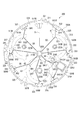
図1は、時計1を時計表面側から見た正面図であり、図2は、時計1の概略を示す断面図である。
時計1は、図1および図2に示すように、外装ケース30と、カバーガラス33と、裏蓋34とを備えている。外装ケース30は、金属で形成された円筒状のケース31に、セラミックで形成されたベゼル32が嵌合されて構成されている。このベゼル32の内周側に、プラスチックで形成されたリング状のダイヤルリング35を介して、円盤状の文字板11が配置されている。
外装ケース30の側面には、Aボタン41と、Bボタン42と、リューズ43とが設けられている。
[Schematic configuration of watch 1]
FIG. 1 is a front view of the
As shown in FIGS. 1 and 2, the
An
時計1は、ケース31の二つの開口のうち、表面側の開口は、ベゼル32を介してカバーガラス33で塞がれており、裏面側の開口は金属で形成された裏蓋34で塞がれている。
外装ケース30の内側には、ベゼル32の内周に取り付けられているダイヤルリング35と、光透過性の文字板11と、指針21〜28と、カレンダー車29と、各指針およびカレンダー車29を駆動する駆動機構140などが備えられている。
In the
Inside the
ダイヤルリング35は、平面視においてはリング形状となっており、断面視においてはすり鉢形状となっている。ダイヤルリング35は、平面視において、文字板11の表面の外周と重なっており、文字板11の見切り径を決めている。また、ダイヤルリング35と、ベゼル32の内周面とによりドーナツ形状の収納空間が形成されており、この収納空間内には、リング状のアンテナ体110が収納されている。
ここで、ダイヤルリング35は、本発明の見切り部材の一例である。
The
Here, the
文字板11は、外装ケース30の内側で時刻を表示する円形の板材であり、ポリカーボネートなどの光透過性の材料で形成され、カバーガラス33との間に各指針を備え、ダイヤルリング35の内側に配置されている。
文字板11と、駆動機構140が取り付けられている地板125との間には、光発電を行うソーラーパネル300が備えられている。ソーラーパネル300の詳細な構成については後述する。
The
A
文字板11、ソーラーパネル300および地板125には、指針21〜28の各指針軸211,221,231,241,251,261,271,281が貫通する穴が形成されている。そして、文字板11、ソーラーパネル300には、カレンダー小窓15の開口部が形成されている。
The
駆動機構140は、地板125に取り付けられ、回路基板120で裏面側から覆われている。駆動機構140は、ステップモーターと歯車などの輪列とを有し、当該ステップモーターが当該輪列を介して各指針軸を回転させることにより各指針を駆動する。
駆動機構140は、具体的には、第1〜第6駆動機構を備える。第1駆動機構は指針22および指針23を駆動し、第2駆動機構は指針21を駆動し、第3駆動機構は指針24を駆動し、第4駆動機構は指針25を駆動し、第5駆動機構は指針26,27,28を駆動し、第6駆動機構はカレンダー車29を駆動する。
The
The
回路基板120は、GPS衛星から送信される衛星信号を受信するGPS受信装置150、制御装置160、記憶装置170を備えている。また、この回路基板120とアンテナ体110とは、アンテナ接続ピン115を用いて接続されている。GPS受信装置150、制御装置160、記憶装置170が設けられた回路基板120の裏蓋34側(裏面側)には、これらの回路部品を覆うための回路押さえ122が設けられている。また、リチウム二次電池などの二次電池130が、地板125と裏蓋34との間に設けられている。二次電池130は、ソーラーパネル300が発電した電力で充電される。
The
[時計1の表示機構]
文字板11の外周部を囲むダイヤルリング35には、棒状に形成された加飾部材としてのインデックス501〜512(バーインデックス)が取り付けられている。インデックス501〜512は、金属などの遮光性を有する材料によって形成されている。
インデックス501〜512は、文字板11の1時位置〜12時位置までの各時を示す位置に対応して等間隔で順番に設けられている。
インデックス501は、平面視において、ダイヤルリング35と重なるインデックス基端部501Aと、インデックス基端部501Aにおける文字板11の平面中心に近づく方向の端縁から、文字板11の平面中心に向かって延出するインデックス延出部501Bとを備える。すなわち、インデックス延出部501Bは、平面視で文字板11と重なっている。
インデックス502〜512についても、インデックス501と同様に、インデックス基端部502A〜512Aと、インデックス延出部502B〜512Bとを備えている。
また、ダイヤルリング35には、各インデックス501〜512の間に、インデックスの間を5分割する目盛が表記されている。
[Display mechanism of clock 1]
The
The
Like the
Further, on the
指針21,22,23は、文字板11の平面中心に、文字板11の表裏方向に沿って設けられた指針軸211,221,231に取り付けられている。
ダイヤルリング35に設けられたインデックス501〜512および目盛を指示することで、指針21(秒針)は第1時刻(ローカルタイム:例えば外国にいる場合の現地時刻)の「秒」を表示し、指針22(分針)は第1時刻の「分」を表示し、指針23(時針)は第1時刻の「時」を表示する。なお、第1時刻の「秒」は、後述する第2時刻の「秒」と同じため、ユーザーは、指針21を確認することで、第2時刻の「秒」も把握できる。
The
By indicating the
指針24は、文字板11の平面中心から2時方向の位置に設けられている指針軸241に取り付けられている。
文字板11のカバーガラス33側の表面(表示面)には、平面視で指針軸241を中心として円弧状に形成された加飾部材としてのサブダイヤル61が取り付けられている。サブダイヤル61は、金属などの遮光性を有する材料によって形成されている。
サブダイヤル61の表面には、七曜を示す「S」、「M」、「T」、「W」、「T」、「F」、「S」の英字が表記されている。指針24は、「S」〜「S」のいずれかを指示することで、曜日を表示する。
The
On the surface (display surface) of the
On the surface of the
指針25は、文字板11の平面中心から10時方向の位置に設けられている指針軸251に取り付けられている。
文字板11の表面には、平面視で指針軸251を中心として円弧状に形成されたサブダイヤル62が取り付けられている。サブダイヤル62は、金属などの遮光性を有する材料によって形成されている。
サブダイヤル62の表面には、夏時間(DST:夏時間ON、○:夏時間OFF)の設定や、二次電池130の電池容量や、機内モードや、衛星信号の受信モードを表す文字や図形が表記されている。指針25は、これらの文字や図形を指示することで、各情報を表示する。
The
A
On the surface of the sub-dial 62, characters and figures representing the setting of daylight saving time (DST: daylight saving time ON, ◯: daylight saving time OFF), the battery capacity of the
指針26、指針27は、文字板11の平面中心から6時方向の同じ位置に設けられている指針軸261,271に取り付けられている。
文字板11の表面には、平面視で指針軸251を中心としてリング状に形成されたサブダイヤル63が取り付けられている。サブダイヤル63は、金属などの遮光性を有する材料によって形成されている。
サブダイヤル63の表面には、内周縁に沿って、時を表す「1」〜「12」の数字が表記されている。また、文字板11の表面には、サブダイヤル63の内周縁に沿って、1周を60分割する目盛が表記されている。
これらの数字や目盛を指示することで、指針26は、第2時刻(ホームタイム:例えば外国にいる場合の日本の時刻)の「分」を表示し、指針27は、第2時刻の「時」を表示する。
The
A ring-shaped
On the surface of the
By indicating these numbers and scales, the
指針28は、文字板11の平面中心から4時方向の位置に設けられている指針軸281に取り付けられている。
文字板11の表面には、平面視で指針軸281を中心としてリング状に形成されたサブダイヤル64が取り付けられている。サブダイヤル64は、金属などの遮光性を有する材料によって形成されている。
サブダイヤル64の表面には、午前を示す「A」の英字、および、午後を示す「P」の英字が表記されている。指針28は、「A」または「P」の英字を指示することで、第2時刻の午前または午後を表示する。
The
A ring-shaped
On the surface of the sub-dial 64, the letter "A" indicating morning and the letter "P" indicating afternoon are written. The
カレンダー小窓15は、文字板11の平面中心から4時方向の位置に設けられている。カレンダー小窓15は、文字板11およびソーラーパネル300を矩形状に開口した開口部に設けられており、開口部からカレンダー車29に印刷された数字が視認可能となっている。カレンダー車29は、開口部から数字を視認させることで、第1時刻に対応した年月日の「日」を表示する。
The calendar
ここで、インデックス延出部501B〜512Bおよびサブダイヤル61〜64は、カバーガラス33側から入射した光を遮光する。これにより、ソーラーパネル300において、平面視でインデックス延出部501B〜512Bおよびサブダイヤル61〜64と重なる領域には、文字板11を透過した光が入射されない。すなわち、インデックス延出部501B〜512Bおよびサブダイヤル61〜64は、本発明の遮光部材の一例である。また、インデックス延出部501B〜512Bは、本発明の目盛部材の一例であり、サブダイヤル61は、本発明の第1サブダイヤルの一例であり、サブダイヤル62は、本発明の第2サブダイヤルの一例であり、サブダイヤル63は、本発明の第3サブダイヤルの一例である。
Here, the
[ソーラーパネル300の構成]
図3は、ソーラーパネル300を示す平面図である。図4は、ソーラーパネル300に、文字板11の表面側に配置されたインデックス延出部501B〜512Bおよびサブダイヤル61〜64を投影した図である。なお、図4において、2点鎖線は、投影部分を示し、点線は、表面側に現れていない、隠れている部分(電極341,342)や、概念的に図示している部分(接続部331〜337、電極引出部338)を示す。
ソーラーパネル300は、光エネルギーを電気エネルギーに変換する光発電を行う光発電素子である。ソーラーパネル300は、図3,4に示すように、平面視略円形状の基材310と、基材310の裏面側に設けられた電極341,342と、基材310の表面側に設けられた、平面視略円形状のソーラーパネル本体300Aとを備える。電極341,342は、ソーラーパネル300の正極および負極であり、図示しないばね部材などの導通部材を介して回路基板120の端子と接続されている。
[Configuration of solar panel 300]
FIG. 3 is a plan view showing the
The
[基材310の構成]
基材310は、合成樹脂製のフィルムなどの絶縁材で構成されている。
基材310の外周径は、ダイヤルリング35の内周径よりも、僅かに大きく形成され、基材310の外周は、平面視においてダイヤルリング35と重なっている。
基材310には、指針軸211,221,231が挿通される挿通孔310Aと、指針軸241が挿通される挿通孔310Bと、指針軸251が挿通される挿通孔310Cと、指針軸261,271が挿通される挿通孔310Dと、指針軸281が挿通される挿通孔310Eと、カレンダー小窓15に対応した開口部310Fが設けられている。
[Configuration of Base Material 310]
The
The outer diameter of the
In the
[ソーラーパネル本体300Aの構成]
ソーラーパネル本体300Aの外周径は、ダイヤルリング35の内周径と、ほぼ同じ大きさで形成され、ソーラーパネル本体300Aの外周縁は、平面視においてダイヤルリング35の内周縁とほぼ一致している。
ソーラーパネル本体300Aは、外周に沿って設けられた複数の接続部331〜337および電極引出部338と、それ以外の部分である発電部320とにより構成されている。
発電部320は、8個のソーラーセル321〜328によって構成されている。ソーラーセル321〜328は、基材310の表面上に、下部電極層、半導体層、絶縁層、上部電極層、透光性の封止樹脂層などを積層することによって構成されている。ソーラーセル321〜328は、アモルファスシリコン系のソーラーセルである。
そして、接続部331〜337は、隣り合うソーラーセルを直列に接続する。また、電極引出部338は、ソーラーセル326,327と電極341、342とを電気的に接続する。
接続部331は文字板11の12時位置に対応して設けられ、接続部332はほぼ1時位置に対応して設けられ、接続部333は3時位置に対応して設けられ、接続部334は5時位置に対応して設けられ、接続部335は6時位置に対応して設けられ、接続部336は8時位置に対応して設けられ、電極引出部338はほぼ9時位置に対応して設けられ、接続部337は11時位置に対応して設けられている。
ここで、平面視において、接続部331〜337は、ダイヤルリング35の内側に位置し、電極引出部338は、一部がダイヤルリング35の内側に位置し、他の部分はダイヤルリング35と重なっている。
なお、接続部331〜337および電極引出部338の具体的な構造については、後述する。
[Structure of solar panel
The outer peripheral diameter of the solar panel
The solar panel
The
And the connection parts 331-337 connect adjacent solar cells in series. In addition, the electrode lead-out
The connecting
Here, in plan view, the connecting
The specific structures of the connecting
[発電部320の構成]
発電部320には、中央部分に、指針軸211,221,231が挿通される挿通孔320Iが設けられている。また、発電部320には、カレンダー小窓15に対応した開口部320Jが設けられている。
そして、発電部320は、挿通孔320Iから外側に向かって放射状に伸びて接続部331〜337および電極引出部338に達する8個の分割線D1〜D8によって、8個のソーラーセル321〜328に分割されている。
[Configuration of Power Generation Unit 320]
The
Then, the
ソーラーセル321は、挿通孔320Iから接続部331まで伸びる分割線D1と、挿通孔320Iから接続部332まで伸びる分割線D2とによって、隣り合う他のソーラーセル328,322と区画されている。分割線D1は直線であり、分割線D2は3つの直線部分と2つの屈曲部分(角部)D21,D22とを有している。
ここで、分割線D1の接続部331側の端部は、平面視において、インデックス延出部512Bと重なっている。
また、分割線D2の屈曲部分D21は、平面視において、サブダイヤル61と重なっている。
The
Here, the end of the dividing line D1 on the side of the connecting
The bent portion D21 of the dividing line D2 overlaps with the
ソーラーセル322は、上記分割線D2と、挿通孔320Iから接続部333まで伸びる分割線D3とによって、隣り合う他のソーラーセル321,323と区画されている。分割線D3は3つの直線部分と2つの屈曲部分D31,D32とを有している。
ここで、平面視において、分割線D3の屈曲部分D31は、サブダイヤル61と重なり、屈曲部分D32および分割線D3の接続部333側の端部は、インデックス延出部503Bと重なっている。
また、ソーラーセル322には、指針軸241が挿通される挿通孔322Aが設けられている。
The
Here, in plan view, the bent portion D31 of the dividing line D3 overlaps the
Further, the
ソーラーセル323は、上記分割線D3と、分割線D4とによって、隣り合う他のソーラーセル322,324と区画されている。分割線D4は、挿通孔320Iから開口部320Jまで伸びる分割線部分D41と、開口部320Jから接続部334までの伸びる分割線部分D42とを有している。分割線部分D41は、3つの直線部分と、2つの屈曲部分D411,D413と、サブダイヤル64の外周に沿って円弧状に湾曲した1つの湾曲部分D412とを有している。分割線部分D42は、2つの直線部分と1つの屈曲部分D421とを有している。
ここで、平面視において、分割線部分D41の屈曲部分D411は、サブダイヤル63と重なり、湾曲部分D412および屈曲部分D413は、サブダイヤル64と重なり、分割線部分D42の屈曲部分D421および分割線部分D42の接続部334側の端部は、インデックス延出部505Bと重なっている。
また、ソーラーセル323には、指針軸281が挿通される挿通孔323Aが設けられている。
The
Here, in plan view, the bent portion D411 of the parting line portion D41 overlaps with the
Further, the
ソーラーセル324は、上記分割線D4と、挿通孔320Iから接続部335まで伸びる分割線D5とによって、隣り合う他のソーラーセル323,325と区画されている。
ソーラーセル324には、指針軸261,271が挿通される挿通孔324Aが設けられている。
そして、分割線D5は、4つの直線部分と、2つの屈曲部分D51,D53と、挿通孔324Aの外周に沿って円弧状に湾曲した1つの湾曲部分D52とを有している。
ここで、分割線D5の屈曲部分D51,D53は、平面視において、サブダイヤル63と重なっている。
The
The
The dividing line D5 has four straight line portions, two bent portions D51 and D53, and one curved portion D52 curved in an arc shape along the outer periphery of the
Here, the bent portions D51 and D53 of the dividing line D5 overlap the
ソーラーセル325は、上記分割線D5と、挿通孔320Iから接続部336まで伸びる分割線D6とによって、隣り合う他のソーラーセル324,326と区画されている。分割線D6は3つの直線部分と2つの屈曲部分D61,D62とを有している。
ここで、平面視において、分割線D6の屈曲部分D61は、サブダイヤル63と重なり、屈曲部分D62および分割線D6の接続部336側の端部は、インデックス延出部508Bと重なっている。
The
Here, in plan view, the bent portion D61 of the dividing line D6 overlaps with the
ソーラーセル326は、上記分割線D6と、挿通孔320Iから電極引出部338まで伸びる分割線D7とによって、隣り合う他のソーラーセル325,327と区画されている。分割線D7は3つの直線部分と2つの屈曲部分D71,D72とを有している。
ここで、平面視において、分割線D7の屈曲部分D71は、サブダイヤル62と重なり、屈曲部分D72および分割線D7の電極引出部338側の端部は、インデックス延出部509Bと重なっている。
The
Here, in plan view, the bent portion D71 of the dividing line D7 overlaps the
ソーラーセル327は、上記分割線D7と、挿通孔320Iから接続部337まで伸びる分割線D8とによって、隣り合う他のソーラーセル326,328と区画されている。分割線D8は3つの直線部分と2つの屈曲部分D81,D82とを有している。
ここで、平面視において、分割線D8の屈曲部分D81は、サブダイヤル62と重なり、屈曲部分D82および分割線D8の接続部337側の端部は、インデックス延出部511Bと重なっている。
また、ソーラーセル327には、指針軸251が挿通される挿通孔327Aが設けられている。
ソーラーセル328は、上記分割線D8と,上記分割線D1とによって、隣り合う他のソーラーセル327,321と区画されている。
The
Here, in plan view, the bent portion D81 of the dividing line D8 overlaps with the
Further, the
The
[接続部331〜337および電極引出部338の構成]
接続部331〜337および電極引出部338は、配線層や絶縁層などによって構成されている。接続部331〜337は、前述したように、隣り合うソーラーセルを直列に接続し、電極引出部338は、ソーラーセル326,327と、ソーラーパネル300の正極および負極である電極341,342とを電気的に接続する。
[Configurations of the
The
接続部331は、図5に示すように、ソーラーセル328から延出した延出部分328Aと、ソーラーセル321から延出した延出部分321Aと、絶縁層331Aと、配線層331Bとを備えている。
延出部分328Aは、下部電極層3281によって構成されている。すなわち、延出部分328Aでは、半導体層3282および上部電極層3283はエッチングによって除去されている。延出部分321Aは、下部電極層3211、半導体層3212および上部電極層3213によって構成されている。
また、延出部分328Aと延出部分321Aとの間は、絶縁層331Aによって分離されている。
そして、延出部分328Aの下部電極層3281の表面から、延出部分321Aの上部電極層3213の表面に亘って配線層331Bが形成されている。
なお、接続部331の表面側は、発電部320の表面を覆う封止樹脂層340によって覆われている。
このような構成により、接続部331は、ソーラーセル328の下部電極層3281とソーラーセル321の上部電極層3213とを接続している。
なお、延出部分321Aは、下部電極層3211、半導体層3212および上部電極層3213を備えているが、表面に遮光性を有する配線層331Bが設けられるため、発電部として機能しない。すなわち、接続部331は、発電しない非発電部となる。
As shown in FIG. 5, the connecting
The extending
The extending
A
The front surface side of the
With such a configuration, the connecting
Note that the
接続部332〜337についても、接続部331と同様の構成を有し、隣り合うソーラーセルの下部電極層と上部電極層とを接続している。
すなわち、接続部332は、ソーラーセル321の下部電極層と、ソーラーセル322の上部電極層とを接続している。
接続部333は、ソーラーセル322の下部電極層と、ソーラーセル323の上部電極層とを接続している。
接続部334は、ソーラーセル323の下部電極層と、ソーラーセル324の上部電極層とを接続している。
接続部335は、ソーラーセル324の下部電極層と、ソーラーセル325の上部電極層とを接続している。
接続部336は、ソーラーセル325の下部電極層と、ソーラーセル326の上部電極層とを接続している。
接続部337は、ソーラーセル327の下部電極層と、ソーラーセル328の上部電極層とを接続している。
The
That is, the connecting
The
The
The connecting
The connecting
The
電極引出部338は、ソーラーセル326の下部電極層と、電極342とを、基材310に設けられた図示しない貫通電極を介して接続している。また、電極引出部338は、ソーラーセル327の上部電極層と、電極341とを、基材310に設けられた図示しない貫通電極を介して接続している。
The electrode lead-out
このように、接続部331〜337および電極引出部338によって、ソーラーパネル300の正極および負極である電極341と電極342との間に、ソーラーセル321〜328が直列接続されている。従って、ソーラーパネル300の出力電圧Vは、8段のソーラーセル321〜328の各出力電圧V1〜V8を加算したものとなる。
Thus, the
そして、本実施形態では、平面視において、各接続部331〜337および電極引出部338は、インデックス延出部501B〜512Bと重なっている。
具体的には、接続部331の一部は、インデックス延出部512Bにおけるインデックス基端部512A側の端部と重なっている。
接続部332の一部は、インデックス延出部501Bにおけるインデックス基端部501A側の端部の一部と重なっている。
接続部333の一部は、インデックス延出部503Bにおけるインデックス基端部503A側の端部と重なっている。
接続部334の一部は、インデックス延出部505Bにおけるインデックス基端部505A側の端部と重なっている。
接続部335の一部は、インデックス延出部506Bと重なっている。
接続部336の一部は、インデックス延出部508Bにおけるインデックス基端部508A側の端部と重なっている。
接続部337は、インデックス延出部511Bにおけるインデックス基端部511A側の端部と重なっている。
電極引出部338の一部は、平面視において、インデックス延出部509Bにおけるインデックス基端部509A側の端部と重なっている。
And in this embodiment, each connection part 331-337 and
Specifically, a part of the connecting
A part of the
A part of the connecting
A part of the connecting
A part of the connecting
A part of the
The connecting
A part of the electrode lead-out
ここで、各ソーラーセル321〜328は直列に接続されているため、ソーラーパネル300の電流値は、各ソーラーセル321〜328のうち、最も電流値が小さいソーラーセルの電流値に制限される。このため、ソーラーパネル300の発電量を最大にするには、各ソーラーセル321〜328の電流値を均一にすることが好ましい。すなわち、各ソーラーセル321〜328で、遮光される部分を除いた発電に有効な面積である受光面積を等しくすることが好ましい。
このため、本実施形態では、各ソーラーセル321〜328において、インデックス延出部501B〜512Bおよびサブダイヤル61〜64と平面視で重なる部分を除いた受光面積が、互いに等しくなるように、分割線D1〜D8が引かれ、各ソーラーセル321〜328の形状や面積が設定されている。
ここで、各ソーラーセル321〜328の受光面積が等しくなるとは、ほぼ等しいことを含み、例えば、各ソーラーセル321〜328の受光面積が、すべてのソーラーセル321〜328の受光面積の平均値に対して±10%以内に納まっている場合などを意味する。
なお、各ソーラーセル321〜328の面積とは、挿通孔320I,322A,323A,324A,327A、開口部320Jなどの開口部分を除いた部分の面積を意味する。
Here, since the
Therefore, in the present embodiment, in each of the solar cells 321-328, the dividing lines are set so that the light-receiving areas excluding the portions overlapping the
Here, the fact that the light receiving areas of the respective
The area of each of the
つまり、本実施形態のように、文字板11の表面側にサブダイヤルが設けられたり、ソーラーセルに開口部が設けられたりしている場合、例えば分割線を等しい角度間隔で放射状に引いた場合は、各ソーラーセルの受光面積を等しくできない。また、サブダイヤルや開口部が設けられていない場合は、分割線を等しい角度間隔で放射状に引くことで、各ソーラーセルの受光面積を等しくすることは可能であるが、ソーラーセルの数が、本実施形態のように12の約数ではない場合(例えば、5,7,8,9,10等の場合)、すべての接続部と、インデックス延出部とを重ねることはできない。
本実施形態では、分割線が直線部分だけではなく、屈曲部分や湾曲部分を備えるため、分割線を自由に引くことができ、各ソーラーセル321〜328の受光面積を等しくし、かつ、接続部331〜337および電極引出部338とインデックス延出部501B〜512Bとを重ねることができる。
That is, as in the present embodiment, when a sub-dial is provided on the front surface side of the
In this embodiment, since the dividing line includes not only a straight line portion but also a bending portion and a curved portion, the dividing line can be freely drawn, the light receiving areas of the respective
[実施形態の作用効果]
ダイヤルリング35の内周縁は、平面視において、ソーラーパネル300の接続部331〜337の外側に位置しているため、ダイヤルリング35が接続部331〜337と重なる場合と比べて、当該内周縁を外側に位置させることができる。これにより、ダイヤルリング35の内側の面積を大きくできるため、その分、ソーラーパネル300の発電部320の面積を大きくでき、発電性能を向上できる。すなわち、ソーラーパネル本体300Aの外周における隣り合う接続部の間の領域を発電部320にできるため、その分、発電部320の面積を大きくできる。これにより、消費電流の大きなGPS受信装置150などのデバイスを内蔵できる。
また、各ソーラーセル321〜328におけるインデックス延出部501B〜512Bと重なる領域は、光が照射されないため、発電しない非発電部である。また、接続部331〜337および電極引出部338も配線層などが設けられるため非発電部である。時計1によれば、各接続部331〜337および電極引出部338の少なくとも一部はインデックス延出部501B〜512Bと重なっているため、各接続部331〜337および電極引出部338がインデックス延出部501B〜512Bと重ならない場合と比べて、非発電部の合計面積を小さくできる。すなわち、発電に有効な部分の面積である有効発電面積を大きくでき、発電性能をより向上できる。
このように、本実施形態では、有効発電面積を大きくできるため、例えば、ソーラーパネル300の発電量が同じ場合、文字板11の光透過率を低く設定することができる。この場合、例えば、各接続部331〜337および電極引出部338において、インデックス延出部501B〜512Bと重なっていない部分を、視認されにくくでき、外観を向上できる。
[Operation and effect of the embodiment]
Since the inner peripheral edge of the
In addition, the regions of the
As described above, in the present embodiment, the effective power generation area can be increased, so that, for example, when the amount of power generated by the
各ソーラーセル321〜328の受光面積が等しいため、ソーラーパネル300の発電量を最大にできる。
Since the
分割線が屈曲部分や湾曲部分を備えることで、例えばすべての分割線が1本の直線で構成されている場合と比べて、分割線を自由に引くことができ、各ソーラーセル321〜328の形状や面積を自由に設定できる。
また、分割線の屈曲部分は、ユーザーによって視認された場合、直線部分よりも目立ちやすいが、時計1によれば、屈曲部分は、サブダイヤル61〜64やインデックス延出部501B〜512Bと重なっているため、ユーザーによって視認されない。これにより、外観を向上できる。
Since the dividing line includes the bent portion and the curved portion, the dividing line can be freely drawn as compared with the case where all the dividing lines are configured by one straight line, and the
Further, the bent portion of the dividing line is more visible than the straight portion when visually recognized by the user, but according to the
インデックス延出部501B〜512Bは、時計表面側から見て、文字板11の外周に沿って12個設けられているため、接続部331〜337の数が、本実施形態のように、12個以下となる場合は、すべての接続部331〜337をインデックス延出部501B〜512Bと重ねることができる。このため、接続部を、例えば、時計表面側から見て、文字板の外周の一部に配置された円弧状のインジケーターなどの遮光部材と重ねる場合など、すべての接続部を遮光部材と重ねることが難しい場合と比べて、接続部と遮光部材とが重なっている面積の合計を大きくできる。これにより、有効発電面積を大きくし、発電性能を向上できる。
As the
[他の実施形態]
なお、本発明は前述の実施形態に限定されるものではなく、本発明の目的を達成できる範囲での変形、改良等は本発明に含まれるものである。
前記実施形態では、文字板11の見切り径は、ダイヤルリング35で決められているが、本発明はこれに限定されない。例えば、外装ケース30の一部が文字板11の表面側に張り出し、平面視において、文字板11の外周と重なることで、見切り径を決めてもよい。この場合、外装ケース30が本発明の見切り部材を構成する。
[Other Embodiments]
It should be noted that the present invention is not limited to the above-described embodiment, and modifications, improvements, etc. within the scope of achieving the object of the present invention are included in the present invention.
In the above embodiment, the parting diameter of the
前記実施形態では、遮光部材は、インデックス延出部501B〜512Bおよびサブダイヤル61〜64であるが、本発明はこれに限定されない。すなわち、遮光性を有し、かつ、指針などとは異なり、ソーラーパネル300の決められた領域と定常的に重なる部材であればよい。このような部材としては、ダイヤルリング35の内周縁に沿って円弧状に形成される遮光性を有するインジケーターや、遮光性を有する円盤に針の図形が印刷された円盤針などが例示できる。
In the above embodiment, the light shielding members are the
前記実施形態では、各接続部331〜337および電極引出部338の一部が、インデックス延出部501B〜512Bと重なっているが、本発明はこれに限定されない。例えば、インデックス延出部501B〜512Bにおけるダイヤルリング35の内周に沿った方向の幅寸法を大きくすることで、各接続部331〜337および電極引出部338の全体が、インデックス延出部501B〜512Bと重なるようにしてもよい。
また、前記実施形態では、すべての接続部331〜337および電極引出部338が、インデックス延出部501B〜512Bと重なっているが、本発明はこれに限定されない。例えば、電極引出部338はインデックス延出部501B〜512Bと重なっていなくてもよい。また、接続部331〜337の少なくとも1つの接続部が、インデックス延出部501B〜512Bのいずれかと重なっていればよい。
また、前記実施形態では、接続部331〜337は、平面視において、ダイヤルリング35の内周縁に沿って設けられているが、本発明はこれに限定されない。すなわち、ダイヤルリング35の内側であれば、どこに設けられていてもよい。
また、前記実施形態では、接続部331〜337は、インデックス延出部501B〜512Bと重なっているが、本発明はこれに限定されない。すなわち、接続部331〜337は、サブダイヤル61〜64や前述のインジケーターや円盤針などの遮光部材と重なっていればよい。
In the above-described embodiment, a part of each of the
Moreover, in the said embodiment, although all the connection parts 331-337 and the electrode lead-out
Further, in the above embodiment, the connecting
Moreover, in the said embodiment, although the connection parts 331-337 overlap with the
前記実施形態では、インデックス501〜512は、ダイヤルリング35に取り付けられているが、本発明はこれに限定されない。例えば、文字板11に取り付けられていてもよい。
また、前記実施形態では、サブダイヤル61〜64は、文字板11とは別体で構成されていたが、本発明はこれに限定されない。すなわち、文字板11に一体形成されていてもよい。この場合、サブダイヤル61〜64は、文字板11と同じ材料で形成されるが、厚み寸法を大きくすることで、遮光性を有するようにできる。
また、サブダイヤル61〜64は、文字板11に対して塗装することで形成するようにしてもよい。
In the above-described embodiment, the
Further, in the above embodiment, the sub dials 61 to 64 are formed separately from the
Further, the sub dials 61 to 64 may be formed by coating the
前記実施形態では、ソーラーセルの数は8個であるが、本発明はこれに限定されない。すなわち、8個以外であってもよい。ただし、5個以上であることが好ましい。
1つのソーラーセルでの起電圧は約0.6〜0.7V程度である。このため、5個以上のソーラーセルを直列に接続すれば、つまり5段以上のソーラーセルとすれば、約0.6〜0.7V×5段=約3〜3.5V程度の起電圧が得られ、例えば2.4V系のリチウム二次電池を満充電することができる。
同様に、例えばソーラーセルの数が7個の場合は、約0.6〜0.7V×7段=約4.2〜4.9V程度の起電圧が得られ、ソーラーセルの数が8個の場合は、約0.6〜0.7V×8段=約4.8〜5.6V程度の起電圧が得られ、例えば3.7V系のリチウム二次電池を満充電することができる。
これにより、起電圧が大きな、例えば2.4V系や3.7V系のリチウム二次電池を電源にできるため、GPS受信装置などの消費電流の大きなデバイスを内蔵できる。
In the above embodiment, the number of solar cells is eight, but the present invention is not limited to this. That is, the number may be other than eight. However, it is preferable that the number is 5 or more.
The electromotive voltage of one solar cell is about 0.6 to 0.7V. Therefore, if five or more solar cells are connected in series, that is, if there are five or more solar cells, an electromotive voltage of about 0.6 to 0.7 V×5 steps=about 3 to 3.5 V is generated. The obtained lithium secondary battery of, for example, 2.4 V can be fully charged.
Similarly, for example, when the number of solar cells is 7, an electromotive voltage of about 0.6 to 0.7 V x 7 stages = about 4.2 to 4.9 V is obtained, and the number of solar cells is 8. In this case, an electromotive voltage of about 0.6 to 0.7 V×8 stages=about 4.8 to 5.6 V can be obtained, and for example, a 3.7 V lithium secondary battery can be fully charged.
As a result, since a lithium secondary battery having a large electromotive voltage, such as a 2.4V type or 3.7V type lithium secondary battery, can be used as a power source, a device with a large current consumption such as a GPS receiver can be incorporated.
前記実施形態では、各ソーラーセル321〜328は、受光面積が等しいが、本発明はこれに限定されない。すなわち、受光面積が異なっていてもよい。
また、前記実施形態では、ソーラーセル321〜328は、アモルファスシリコン系のソーラーセルであったが、本発明はこれに限定されない。ソーラーセル321〜328は、他の種類のソーラーセルであってもよい。
In the above embodiment, the
Further, in the above-described embodiment, the
前記実施形態では、分割線は屈曲部分を備えているが、本発明はこれに限定されない。例えば、分割線は、屈曲部分を備えずに、湾曲部分や直線部分のみによって構成されていてもよい。 In the above embodiment, the dividing line has the bent portion, but the present invention is not limited to this. For example, the dividing line may be configured by only a curved portion or a straight portion without having a bent portion.
前記実施形態では、本発明を、アンテナ体110およびGPS受信装置150を内蔵した時計に適用したものを例示しているが、本発明は、アンテナや受信装置を内蔵していない時計に適用することもできる。
In the above-described embodiment, the present invention is applied to the timepiece having the
前記実施形態の各接続部331〜337では、隣り合うソーラーセルの一方から延出した下部電極層と、他方から延出した上部電極層とが、配線層によって接続されているが、本発明はこれに限定されない。例えば、下部電極層と上部電極層とが、レーザーボンディングなどの他の接続方法によって接続されていてもよい。
In each of the
1…時計、11…文字板、15…カレンダー小窓、21〜28…指針、300…ソーラーパネル、300A…ソーラーパネル本体、310…基材、310A〜310E,320I,322A,323A,324A,327A…挿通孔、310F,320J…開口部、320…発電部、321〜328…ソーラーセル、331〜337…接続部、338…電極引出部、35…ダイヤルリング(見切り部材)、501〜512…インデックス、501B〜512B…インデックス延出部(遮光部材、目盛部材)、61…サブダイヤル(遮光部材、第1サブダイヤル)、62…サブダイヤル(遮光部材、第2サブダイヤル)、63…サブダイヤル(遮光部材、第3サブダイヤル)、64…サブダイヤル(遮光部材)、D1〜D8…分割線、D21,D31,D32,D411,D413,D421,D51,D61,D62,D71,D72,D81,D82…屈曲部分。
DESCRIPTION OF
Claims (5)
複数のソーラーセルを有するソーラーパネルと、
前記ソーラーパネルの表面側に設けられ、透光性を有する文字板と、
前記文字板の表面側に設けられ、時計表面側から見て、前記文字板の外周と重なる見切り部材と、
前記文字板の前記表面側で、かつ、前記見切り部材の内側に設けられた遮光部材と、を備え、
前記遮光部材は、前記時針によって指示されることで時が表示される目盛部材を備え、
前記ソーラーセルを隣り合う他のソーラーセルと区画するすべての分割線は、前記ソーラーパネルの中央から外周に向かって伸びており、
前記ソーラーパネルには、時計表面側から見て、隣り合う前記ソーラーセルを直列に接続する接続部が、前記ソーラーパネルの外周に沿って且つ平面視において前記見切り部材の内側に設けられ、
前記接続部すべてについて、各接続部の少なくとも一部は、時計表面側から見て、前記目盛部材と重なっている
ことを特徴とする時計。 An hour hand,
A solar panel having a plurality of solar cells,
A dial plate provided on the front surface side of the solar panel and having a light-transmitting property,
A parting member that is provided on the front surface side of the dial and overlaps with the outer periphery of the dial when viewed from the front surface side of the timepiece,
On the front surface side of the dial, and a light blocking member provided inside the parting member,
The light-shielding member includes a scale member that displays time when instructed by the hour hand,
All the dividing lines that divide the solar cell from other adjacent solar cells extend from the center of the solar panel toward the outer periphery,
Wherein the solar panel, as viewed from the watch face side, connecting portions for connecting the solar cells adjacent in series, provided inside the parting member in and viewed along the outer periphery of the solar panel,
At least a part of each connecting portion of all the connecting portions overlaps with the scale member when viewed from the front surface side of the timepiece.
各ソーラーセルは、前記文字板を透過する光を受光する受光面積が互いに等しい
ことを特徴とする時計。 The watch according to claim 1,
The timepieces are characterized in that the respective solar cells have the same light receiving area for receiving the light transmitted through the dial plate.
前記ソーラーセルを隣り合う前記ソーラーセルと区画する分割線は、屈曲部分を備え、
前記屈曲部分は、時計表面側から見て、前記遮光部材と重なっている
ことを特徴とする時計。 In the timepiece according to claim 1 or 2,
The dividing line that divides the solar cell from the adjacent solar cells includes a bent portion,
The bent portion overlaps with the light shielding member when viewed from the front surface side of the timepiece.
前記ソーラーパネルは、5個以上のソーラーセルを有している
ことを特徴とする時計。 The watch according to any one of claims 1 to 3,
The solar panel has five or more solar cells.
前記遮光部材として、前記見切り部材の内周に沿って等間隔で設けられた12個の目盛部材と、時計表面側から見て、前記文字板の平面中心に対して、2時方向側に設けられた第1サブダイヤルと、10時方向側に設けられた第2サブダイヤルと、6時方向側に設けられた第3サブダイヤルと、を備え、
前記ソーラーパネルは、8個のソーラーセルを有し、
前記ソーラーパネルには、前記文字板の4時位置に対応した位置に開口部が設けられ、
前記接続部は、前記文字板の12時位置、1時位置、3時位置、5時位置、6時位置、8時位置、11時位置にそれぞれ対応した位置に設けられ、
各接続部の少なくとも一部は、時計表面側から見て、前記目盛部材と重なっている
ことを特徴とする時計。 In the timepiece according to any one of claims 1 to 4,
As the light-shielding member, twelve scale members provided at equal intervals along the inner circumference of the parting member, and provided on the 2 o'clock side with respect to the plane center of the dial when viewed from the timepiece surface side. A first sub-dial, a second sub-dial provided on the 10 o'clock direction side, and a third sub-dial provided on the 6 o'clock direction side,
The solar panel has 8 solar cells,
The solar panel is provided with an opening at a position corresponding to the 4 o'clock position of the dial,
The connecting portion is provided at a position corresponding to the 12 o'clock position, 1 o'clock position, 3 o'clock position, 5 o'clock position, 6 o'clock position, 8 o'clock position, 11 o'clock position of the dial, respectively.
At least a part of each connecting portion overlaps with the scale member when viewed from the front surface side of the timepiece.
Priority Applications (2)
| Application Number | Priority Date | Filing Date | Title |
|---|---|---|---|
| JP2015144949A JP6740574B2 (en) | 2015-07-22 | 2015-07-22 | clock |
| US15/208,881 US10042327B2 (en) | 2015-07-22 | 2016-07-13 | Timepiece |
Applications Claiming Priority (1)
| Application Number | Priority Date | Filing Date | Title |
|---|---|---|---|
| JP2015144949A JP6740574B2 (en) | 2015-07-22 | 2015-07-22 | clock |
Publications (3)
| Publication Number | Publication Date |
|---|---|
| JP2017026454A JP2017026454A (en) | 2017-02-02 |
| JP2017026454A5 JP2017026454A5 (en) | 2018-08-30 |
| JP6740574B2 true JP6740574B2 (en) | 2020-08-19 |
Family
ID=57837285
Family Applications (1)
| Application Number | Title | Priority Date | Filing Date |
|---|---|---|---|
| JP2015144949A Active JP6740574B2 (en) | 2015-07-22 | 2015-07-22 | clock |
Country Status (2)
| Country | Link |
|---|---|
| US (1) | US10042327B2 (en) |
| JP (1) | JP6740574B2 (en) |
Families Citing this family (7)
| Publication number | Priority date | Publication date | Assignee | Title |
|---|---|---|---|---|
| JP2018054598A (en) * | 2016-09-26 | 2018-04-05 | セイコーインスツル株式会社 | Movement and timepiece |
| JP6888356B2 (en) * | 2017-03-21 | 2021-06-16 | セイコーエプソン株式会社 | Electronic clock |
| JP2019020267A (en) * | 2017-07-18 | 2019-02-07 | セイコーインスツル株式会社 | Timepiece |
| JP7098946B2 (en) * | 2018-02-01 | 2022-07-12 | セイコーエプソン株式会社 | Movements and watches with solar cells |
| JP6763415B2 (en) * | 2018-03-14 | 2020-09-30 | カシオ計算機株式会社 | Solar panels, display devices and clocks |
| JP6891914B2 (en) * | 2019-03-26 | 2021-06-18 | カシオ計算機株式会社 | Solar panels, display devices and clocks |
| WO2020229880A1 (en) * | 2019-05-16 | 2020-11-19 | Garmin Switzerland | Semi-transparent multi-cell photovoltaic module subjected to recurrent peripheral shade |
Family Cites Families (21)
| Publication number | Priority date | Publication date | Assignee | Title |
|---|---|---|---|---|
| US3427797A (en) * | 1966-12-12 | 1969-02-18 | Kenjiro Kimura | Timepiece using a solar battery as the power source |
| JPS5217746B1 (en) * | 1971-07-09 | 1977-05-17 | ||
| JPS5353491Y2 (en) * | 1973-03-27 | 1978-12-21 | ||
| JPS51121365A (en) * | 1975-04-17 | 1976-10-23 | Seiko Epson Corp | Electric clock |
| US4261049A (en) * | 1977-11-16 | 1981-04-07 | Citizen Watch Co., Ltd. | Wristwatch with solar cells |
| JPS60100688U (en) * | 1983-12-14 | 1985-07-09 | セイコーエプソン株式会社 | electronic clock |
| JP3489377B2 (en) | 1997-02-27 | 2004-01-19 | セイコーエプソン株式会社 | Display unit structure with solar cell, electronic device with solar cell and clock using the same |
| CN1161674C (en) * | 1998-11-26 | 2004-08-11 | 时至准钟表股份有限公司 | Timepiece |
| JP3593917B2 (en) | 1999-03-31 | 2004-11-24 | セイコーエプソン株式会社 | Timing device |
| WO2001071434A1 (en) * | 2000-03-21 | 2001-09-27 | Citizen Watch Co., Ltd. | Electronic unit |
| JP3633446B2 (en) | 2000-06-21 | 2005-03-30 | セイコーエプソン株式会社 | Clock with solar battery |
| JP2002148362A (en) * | 2001-09-17 | 2002-05-22 | Seiko Epson Corp | Timepiece with solar cell |
| CN1942835A (en) * | 2004-04-13 | 2007-04-04 | 西铁城时计株式会社 | Electronic device provided with solar cell |
| JP5598257B2 (en) * | 2010-10-28 | 2014-10-01 | カシオ計算機株式会社 | Electronics |
| JP5888071B2 (en) * | 2012-04-02 | 2016-03-16 | カシオ計算機株式会社 | Solar power generator and electronic watch |
| JP5900181B2 (en) | 2012-06-19 | 2016-04-06 | セイコーエプソン株式会社 | Electronic clock with solar battery |
| JP6008181B2 (en) * | 2012-09-04 | 2016-10-19 | カシオ計算機株式会社 | Solar panels and watches |
| JP6136380B2 (en) | 2013-03-07 | 2017-05-31 | セイコーエプソン株式会社 | Electronic clock |
| JP6048222B2 (en) * | 2013-03-04 | 2016-12-21 | カシオ計算機株式会社 | Solar panels and watches |
| JP6269945B2 (en) * | 2013-09-04 | 2018-01-31 | カシオ計算機株式会社 | Solar panels and watches |
| US9823625B2 (en) * | 2014-03-18 | 2017-11-21 | Casio Computer Co., Ltd. | Electronic device |
-
2015
- 2015-07-22 JP JP2015144949A patent/JP6740574B2/en active Active
-
2016
- 2016-07-13 US US15/208,881 patent/US10042327B2/en not_active Expired - Fee Related
Also Published As
| Publication number | Publication date |
|---|---|
| US20170023915A1 (en) | 2017-01-26 |
| JP2017026454A (en) | 2017-02-02 |
| US10042327B2 (en) | 2018-08-07 |
Similar Documents
| Publication | Publication Date | Title |
|---|---|---|
| JP6740574B2 (en) | clock | |
| EP3042396B1 (en) | Solar panel and timepiece including solar panel | |
| US3427797A (en) | Timepiece using a solar battery as the power source | |
| JP5087071B2 (en) | Radio correction clock | |
| JP6638247B2 (en) | Electronic clock | |
| US10056516B2 (en) | Solar panel | |
| WO2000031596A1 (en) | Timepiece | |
| JP2007285748A (en) | Wrist watch | |
| WO2001071434A1 (en) | Electronic unit | |
| JP6544425B2 (en) | Solar panels and watches | |
| JP5799703B2 (en) | Electronic clock and secondary battery unit | |
| JP7225577B2 (en) | electronic clock | |
| JP7267145B2 (en) | clock | |
| US20230057778A1 (en) | Watch | |
| JP2019128306A (en) | Electronic timepiece | |
| CN115840348A (en) | Electronic device and timepiece | |
| JP2012185141A (en) | Chronometer | |
| JP6327381B2 (en) | Secondary battery unit and solar panel electronic watch | |
| JP2015129685A (en) | Electronic timepiece with solar battery | |
| JP6128175B2 (en) | Clock movement and clock | |
| JP2018054598A (en) | Movement and timepiece | |
| JP2019020267A (en) | Timepiece | |
| JP2011163877A (en) | Timepiece | |
| JP2006118966A (en) | Timepiece with calendar display function | |
| JP2016048763A (en) | Solar cell module and clock with solar cell |
Legal Events
| Date | Code | Title | Description |
|---|---|---|---|
| A521 | Written amendment |
Free format text: JAPANESE INTERMEDIATE CODE: A523 Effective date: 20180719 |
|
| A621 | Written request for application examination |
Free format text: JAPANESE INTERMEDIATE CODE: A621 Effective date: 20180719 |
|
| A977 | Report on retrieval |
Free format text: JAPANESE INTERMEDIATE CODE: A971007 Effective date: 20190529 |
|
| A131 | Notification of reasons for refusal |
Free format text: JAPANESE INTERMEDIATE CODE: A131 Effective date: 20190625 |
|
| A521 | Written amendment |
Free format text: JAPANESE INTERMEDIATE CODE: A523 Effective date: 20190822 |
|
| A131 | Notification of reasons for refusal |
Free format text: JAPANESE INTERMEDIATE CODE: A131 Effective date: 20200107 |
|
| A521 | Written amendment |
Free format text: JAPANESE INTERMEDIATE CODE: A523 Effective date: 20200309 |
|
| TRDD | Decision of grant or rejection written | ||
| A01 | Written decision to grant a patent or to grant a registration (utility model) |
Free format text: JAPANESE INTERMEDIATE CODE: A01 Effective date: 20200623 |
|
| A61 | First payment of annual fees (during grant procedure) |
Free format text: JAPANESE INTERMEDIATE CODE: A61 Effective date: 20200706 |
|
| R150 | Certificate of patent or registration of utility model |
Ref document number: 6740574 Country of ref document: JP Free format text: JAPANESE INTERMEDIATE CODE: R150 |