JP7078024B2 - Solar panels, electronic devices and electronic clocks - Google Patents
Solar panels, electronic devices and electronic clocks Download PDFInfo
- Publication number
- JP7078024B2 JP7078024B2 JP2019188385A JP2019188385A JP7078024B2 JP 7078024 B2 JP7078024 B2 JP 7078024B2 JP 2019188385 A JP2019188385 A JP 2019188385A JP 2019188385 A JP2019188385 A JP 2019188385A JP 7078024 B2 JP7078024 B2 JP 7078024B2
- Authority
- JP
- Japan
- Prior art keywords
- power generation
- solar panel
- cells
- generation region
- outer peripheral
- Prior art date
- Legal status (The legal status is an assumption and is not a legal conclusion. Google has not performed a legal analysis and makes no representation as to the accuracy of the status listed.)
- Active
Links
Images


Classifications
-
- H—ELECTRICITY
- H10—SEMICONDUCTOR DEVICES; ELECTRIC SOLID-STATE DEVICES NOT OTHERWISE PROVIDED FOR
- H10F—INORGANIC SEMICONDUCTOR DEVICES SENSITIVE TO INFRARED RADIATION, LIGHT, ELECTROMAGNETIC RADIATION OF SHORTER WAVELENGTH OR CORPUSCULAR RADIATION
- H10F19/00—Integrated devices, or assemblies of multiple devices, comprising at least one photovoltaic cell covered by group H10F10/00, e.g. photovoltaic modules
- H10F19/30—Integrated devices, or assemblies of multiple devices, comprising at least one photovoltaic cell covered by group H10F10/00, e.g. photovoltaic modules comprising thin-film photovoltaic cells
- H10F19/31—Integrated devices, or assemblies of multiple devices, comprising at least one photovoltaic cell covered by group H10F10/00, e.g. photovoltaic modules comprising thin-film photovoltaic cells having multiple laterally adjacent thin-film photovoltaic cells deposited on the same substrate
- H10F19/37—Integrated devices, or assemblies of multiple devices, comprising at least one photovoltaic cell covered by group H10F10/00, e.g. photovoltaic modules comprising thin-film photovoltaic cells having multiple laterally adjacent thin-film photovoltaic cells deposited on the same substrate comprising means for obtaining partial light transmission through the integrated devices, or the assemblies of multiple devices, e.g. partially transparent thin-film photovoltaic modules for windows
-
- G—PHYSICS
- G04—HOROLOGY
- G04C—ELECTROMECHANICAL CLOCKS OR WATCHES
- G04C10/00—Arrangements of electric power supplies in time-pieces
- G04C10/02—Arrangements of electric power supplies in time-pieces the power supply being a radioactive or photovoltaic source
-
- G—PHYSICS
- G04—HOROLOGY
- G04R—RADIO-CONTROLLED TIME-PIECES
- G04R60/00—Constructional details
- G04R60/06—Antennas attached to or integrated in clock or watch bodies
- G04R60/08—Antennas attached to or integrated in clock or watch bodies inside bezels
-
- H—ELECTRICITY
- H10—SEMICONDUCTOR DEVICES; ELECTRIC SOLID-STATE DEVICES NOT OTHERWISE PROVIDED FOR
- H10F—INORGANIC SEMICONDUCTOR DEVICES SENSITIVE TO INFRARED RADIATION, LIGHT, ELECTROMAGNETIC RADIATION OF SHORTER WAVELENGTH OR CORPUSCULAR RADIATION
- H10F19/00—Integrated devices, or assemblies of multiple devices, comprising at least one photovoltaic cell covered by group H10F10/00, e.g. photovoltaic modules
- H10F19/30—Integrated devices, or assemblies of multiple devices, comprising at least one photovoltaic cell covered by group H10F10/00, e.g. photovoltaic modules comprising thin-film photovoltaic cells
- H10F19/31—Integrated devices, or assemblies of multiple devices, comprising at least one photovoltaic cell covered by group H10F10/00, e.g. photovoltaic modules comprising thin-film photovoltaic cells having multiple laterally adjacent thin-film photovoltaic cells deposited on the same substrate
- H10F19/35—Structures for the connecting of adjacent photovoltaic cells, e.g. interconnections or insulating spacers
-
- H—ELECTRICITY
- H10—SEMICONDUCTOR DEVICES; ELECTRIC SOLID-STATE DEVICES NOT OTHERWISE PROVIDED FOR
- H10F—INORGANIC SEMICONDUCTOR DEVICES SENSITIVE TO INFRARED RADIATION, LIGHT, ELECTROMAGNETIC RADIATION OF SHORTER WAVELENGTH OR CORPUSCULAR RADIATION
- H10F77/00—Constructional details of devices covered by this subclass
- H10F77/20—Electrodes
- H10F77/206—Electrodes for devices having potential barriers
- H10F77/211—Electrodes for devices having potential barriers for photovoltaic cells
-
- G—PHYSICS
- G04—HOROLOGY
- G04G—ELECTRONIC TIME-PIECES
- G04G21/00—Input or output devices integrated in time-pieces
- G04G21/04—Input or output devices integrated in time-pieces using radio waves
-
- H—ELECTRICITY
- H01—ELECTRIC ELEMENTS
- H01Q—ANTENNAS, i.e. RADIO AERIALS
- H01Q1/00—Details of, or arrangements associated with, antennas
- H01Q1/27—Adaptation for use in or on movable bodies
- H01Q1/273—Adaptation for carrying or wearing by persons or animals
-
- Y—GENERAL TAGGING OF NEW TECHNOLOGICAL DEVELOPMENTS; GENERAL TAGGING OF CROSS-SECTIONAL TECHNOLOGIES SPANNING OVER SEVERAL SECTIONS OF THE IPC; TECHNICAL SUBJECTS COVERED BY FORMER USPC CROSS-REFERENCE ART COLLECTIONS [XRACs] AND DIGESTS
- Y02—TECHNOLOGIES OR APPLICATIONS FOR MITIGATION OR ADAPTATION AGAINST CLIMATE CHANGE
- Y02E—REDUCTION OF GREENHOUSE GAS [GHG] EMISSIONS, RELATED TO ENERGY GENERATION, TRANSMISSION OR DISTRIBUTION
- Y02E10/00—Energy generation through renewable energy sources
- Y02E10/50—Photovoltaic [PV] energy
- Y02E10/52—PV systems with concentrators
Landscapes
- Physics & Mathematics (AREA)
- General Physics & Mathematics (AREA)
- Engineering & Computer Science (AREA)
- Power Engineering (AREA)
- Electric Clocks (AREA)
- Electromechanical Clocks (AREA)
- Photovoltaic Devices (AREA)
- Life Sciences & Earth Sciences (AREA)
- Sustainable Development (AREA)
- Sustainable Energy (AREA)
Description
本発明は、ソーラーパネル、電子機器及び電子時計に関するものである。 The present invention relates to solar panels, electronic devices and electronic clocks.
従来、光を受光して発電するソーラーパネルを備える時計等の電子機器(電子時計)が広く知られている。
そして近年の各種電子機器の高機能化に伴い、ソーラーパネルによる発電量をより多く確保したいとの要請が高まっている。
このため、電子機器における表示部が設けられている位置等にも発電部を配置して、効率よく発電を行うことが提案されており、例えば特許文献1には、外部から視認されにくく構成した透光発電領域が設けられたソーラーパネルを表示装置に搭載することが記載されている。
このような技術によれば、ソーラーパネルを表示部の上に配置した場合でも表示部の視認性が確保され、発電量の増大と良好な表示の実現とを両立させることができる。
Conventionally, electronic devices (electronic clocks) such as clocks equipped with a solar panel that receives light to generate electricity are widely known.
With the increasing functionality of various electronic devices in recent years, there is an increasing demand for securing more power generation from solar panels.
For this reason, it has been proposed to arrange a power generation unit at a position where a display unit is provided in an electronic device to efficiently generate power. For example,
According to such a technique, the visibility of the display unit is ensured even when the solar panel is arranged on the display unit, and it is possible to achieve both an increase in power generation amount and a good display.
透光発電領域は、例えば、細線化された発電部と光を透過させる透光部とを交互に配置してストライプ状に構成される。
ソーラーパネルは、電圧を調整するために複数のセルに分割することが行われるが、上記のようにストライプ状に構成された部分がある場合には、分割線が目立たないように、ストライプの延在方向に沿って分割される。このため各セルが短冊状に形成され、これを繋ぎ合わせてソーラーパネルが構成されていた。
The translucent power generation region is configured in a striped shape, for example, by alternately arranging thin-wired power generation portions and translucent portions that transmit light.
The solar panel is divided into multiple cells to adjust the voltage, but if there is a striped part as described above, the stripes are extended so that the dividing lines are not noticeable. It is divided along the current direction. For this reason, each cell was formed in a strip shape, and these cells were connected to form a solar panel.
しかしながら、電子機器にアンテナが搭載される場合に、上記のような構成のようなソーラーパネルをアンテナの近傍に配置すると、当該ソーラーパネルの形状、配置、接続方法等によってはアンテナに影響を及ぼし、アンテナの任意周波数における利得が低下してしまうとの問題がある。 However, when an antenna is mounted on an electronic device, if a solar panel having the above configuration is placed in the vicinity of the antenna, the antenna may be affected depending on the shape, arrangement, connection method, etc. of the solar panel. There is a problem that the gain at an arbitrary frequency of the antenna is lowered.
本発明は以上のような事情に鑑みてなされたものであり、アンテナの近傍に配置した場合にアンテナの特性に影響を及ぼしにくいソーラーパネル、電子機器及び電子時計を提供することを目的とするものである。 The present invention has been made in view of the above circumstances, and an object of the present invention is to provide a solar panel, an electronic device, and an electronic clock that do not easily affect the characteristics of the antenna when arranged in the vicinity of the antenna. Is.
前記課題を解決するために、本発明に係るソーラーパネルは、
所望の周波数の電波と共振するように構成された環状部材の近傍に配置され、複数のセルに分割されたソーラーパネルであって、
前記環状部材の直径方向における中央部の領域であって、所定の方向に延在する細線状の発電部が延在方向に直交する方向に並列配置された透光発電領域と、
前記透光発電領域の外周部の領域であって、周方向に沿って前記複数のセルの一部が配置された外周発電領域と、
を備え、
前記複数のセルは、前記外周発電領域の少なくとも一部分と前記透光発電領域の少なくとも一部分とを含んで構成される複合セルを含み、
前記環状部材の直径方向における一端側に前記複数のセルのうち前記複合セルが配置され、前記直径方向の他端側には前記複数のセルのうち前記外周発電領域で構成され前記透光発電領域を含まないセルが配置されていることを特徴とする。
In order to solve the above problems, the solar panel according to the present invention is
A solar panel arranged in the vicinity of an annular member configured to resonate with a radio wave of a desired frequency and divided into a plurality of cells.
A photovoltaic power generation region, which is a central region in the diameter direction of the annular member and in which thin linear power generation portions extending in a predetermined direction are arranged in parallel in a direction orthogonal to the extending direction.
An outer peripheral power generation region in which a part of the plurality of cells is arranged along the circumferential direction, which is a region of the outer peripheral portion of the translucent power generation region.
Equipped with
The plurality of cells include a composite cell configured to include at least a part of the peripheral power generation area and at least a part of the photovoltaic power generation area.
The composite cell of the plurality of cells is arranged on one end side in the radial direction of the annular member, and the outer peripheral power generation region of the plurality of cells is formed on the other end side in the radial direction. It is characterized in that cells that do not contain the above are arranged.
本発明によれば、アンテナの近傍にソーラーパネルを配置した場合にアンテナの特性に影響を及ぼしにくいという効果を奏する。 According to the present invention, when the solar panel is arranged in the vicinity of the antenna, it has an effect that the characteristics of the antenna are not easily affected.
図1から図5を参照しつつ、本発明に係るソーラーパネル及びこれを適用した電子機器としての電子時計の一実施形態について説明する。
なお、以下に述べる実施形態には、本発明を実施するために技術的に好ましい種々の限定が付されているが、本発明の範囲を以下の実施形態及び図示例に限定するものではない。
An embodiment of a solar panel according to the present invention and an electronic clock as an electronic device to which the solar panel is applied will be described with reference to FIGS. 1 to 5.
Although the embodiments described below are provided with various technically preferable limitations for carrying out the present invention, the scope of the present invention is not limited to the following embodiments and illustrated examples.
図1は、本実施形態における電子機器としての電子時計(以下単に「時計」とする。)を示す正面図である。
図1に示すように、本実施形態における時計100は、ケース(以下、実施形態において「本体ケース1」とする。)を備えている。本体ケース1は、例えば硬質の合成樹脂又はチタニウムやステンレス鋼(SUS)等の金属等、硬質な材料で形成されている。なお、本体ケース1を形成する材料はここに例示したものに限定されない。
本実施形態の本体ケース1は、ケース厚み方向における上下(時計における表裏)に開口する中空の短柱形状に形成されている。
FIG. 1 is a front view showing an electronic clock (hereinafter, simply referred to as “clock”) as an electronic device in the present embodiment.
As shown in FIG. 1, the
The
本体ケース1の図1における上下両端部、つまりアナログ方式の時計における12時方向側の端部及び6時方向側の端部には、図示しない時計バンドが取り付けられるバンド取付け部11が設けられている。
また、時計100は、本体ケース1の側部等に操作ボタン12を備えている。図1に示す例では、本体ケース1の左側部に2つ、右側部に3つ、計5つの操作ボタン12が配置されている。
また、本体ケース1の裏面側には、開口部分を閉塞する図示しない裏蓋が取り付けられている。
A
Further, the
Further, a back cover (not shown) that closes the opening portion is attached to the back surface side of the
さらに、本体ケース1における外側上部(時計100における視認側、表面側)には、環状部材として環状のベゼル6が配設されている。
本実施形態においてベゼル6は、所望の周波数の電波と共振するように構成されており、アンテナ(ベゼルアンテナ)として機能する。ベゼル6は図示しないコネクタ等を介して回路基板(図示せず)に実装された受信回路65に接続されており、設定されている周波数の電波を受信するようになっている。例えば、ベゼル6は、後述するようにGPS(global Positioning System)衛星から送信される電波等を受信可能に調整されて時計100の本体ケース1に組付けられており、所定波長の円偏波(GPS電波を受信する場合には、右旋円偏波)の電波を受信する円偏波アンテナとして作用する。
なお、本実施形態におけるベゼル6は一点給電方式のアンテナとして構成され、給電点62は、後述するように図3に網掛け丸印で示すいずれかの位置に設けることが好ましい。
Further, an
In the present embodiment, the
The
アンテナとして機能するベゼル6によって受信可能な所望の周波数の電波としては、衛星から送信される電波が挙げられる。
例えば、GPS衛星からの電波や日本の準天頂衛星であるQZSSから送信される電波の周波数は1575.42MHzであり、GLONASS(Global Navigation Satellite System)から送信される電波は1602.5625MHzを中心とする周波数帯となっている。
このため、例えば、ベゼル6を上記GPS等に対応した周波数1575.42MHzの電波や、GLONASSに対応した周波数1602.5625MHzの電波と共振可能な構成とすれば、GPSやGLONASSから送信された電波を受信することが可能となり、これらの電波に含まれる時刻情報や位置情報を時計100において利用することが可能となる。
本実施形態では、ベゼル6やその他各種の条件を適宜設定することにより、ベゼル6を所望の周波数の電波を受信可能なアンテナとして機能させるようになっている。
なお、アンテナとして機能するベゼル6によって受信可能な所望の周波数の電波は、GPS衛星等から送信される電波に限定されない。
Radio waves of a desired frequency that can be received by the
For example, the frequency of radio waves transmitted from GPS satellites and QZSS, which is a quasi-zenith satellite in Japan, is 1575.42 MHz, and radio waves transmitted from GRONASS (Global Navigation Satellite System) are centered at 1602.5625 MHz. It is a frequency band.
Therefore, for example, if the
In the present embodiment, the
The radio wave of a desired frequency that can be received by the
本実施形態において、ベゼル6は、例えば、SUS316(ステンレス鋼316)等の金属材料により環状に形成されている。
なお、ベゼル6を形成する材料は、SUS316に限定されない。
ただし、本実施形態において、ベゼル6は、前述のように所望の周波数の電波と共振状態となるアンテナとして機能するように構成されている。この点、形成材料の導電率が低い場合(抵抗率が高い場合)には、十分なアンテナ利得が得られないと考えられる。
このため、ベゼル6を良好なアンテナ利得を有するアンテナとして機能させるために、ベゼル6を形成する材料としては、導電率が一定程度以上(すなわち、抵抗率が一定程度以下)であり、透磁率が一定程度以下である金属材料を用いることが好ましい。
なお、ベゼル6を形成する材料は、アンテナとしてのベゼル6によって受信したい電波の周波数、その他各種の条件により適宜設定されるべきものであり、ここに例示したものに限定されるものではない。
In the present embodiment, the
The material forming the
However, in the present embodiment, the
Therefore, in order to make the
The material forming the
図2は、図1に示す時計の模式的な要部断面図である。
図2では、時計100の上部(時計100における視認側、表面側)の要部を断面として模式的に示している。
図2に示すように、ベゼル6の内側には、樹脂等で形成された封止リング32を介して風防部材3が設けられている。
風防部材3は、透明なガラスや樹脂等で形成されており、光透過性を有している。風防部材3が封止リング32を介してベゼル6に嵌装されることにより、本体ケース1の表面側(時計における視認側、上側)の開口が気密を保った状態で閉塞される。
FIG. 2 is a schematic cross-sectional view of a main part of the timepiece shown in FIG.
In FIG. 2, a main part of the upper part of the timepiece 100 (the visible side and the surface side of the timepiece 100) is schematically shown as a cross section.
As shown in FIG. 2, a
The
本実施形態において風防部材3の下面(本体ケース1の内側に配置される面)側の外周部はリング状の装飾部(図示せず)となっていることが好ましい。装飾部として、光透過性を阻害しない手法により全体に総柄模様や着色等を施し、各種のロゴ等の文字や記号、目盛等を設けることで、本体ケース1の内部に収容される表示部4やソーラーパネル5等の外周部の接続部等を覆って外部から視認されないようにする目隠しの機能を持たせることができる。
なお、装飾部の形成の仕方は特に限定されず、例えば風防部材3の下面に印刷や各種蒸着等を施すことで形成される。
In the present embodiment, it is preferable that the outer peripheral portion of the
The method of forming the decorative portion is not particularly limited, and is formed by, for example, printing or various vapor deposition on the lower surface of the
また、本実施形態における本体ケース1の内部には、電子機器としての時計100の各部を動作させるモジュール(計時処理を実行する計時部である計時回路等を含む時計モジュール、図示せず)が収容されている。
モジュールの上方(時計における視認側、表面側)であって風防部材3との間には、液晶ディスプレイ(LCD:Liquid Crystal Display)、有機エレクトロルミネッセンスディスプレイその他のフラットディスプレイ等を備える表示部4が設けられている。表示部4が液晶ディスプレイを備える場合、反射型の液晶ディスプレイでもよいし、バックライトによる透過型の液晶ディスプレイでもよい。表示部4は、後述するソーラーパネル5の下側(すなわち非視認側)に配置される。図1では図示を省略しているが、表示部4には、時刻や各種の情報等が表示されるようになっている。
なお、表示部4の構成は、特に限定されず、文字板及び指針等を備えるアナログ方式の表示手段を有するものであってもよい。また、液晶パネル等を備えて構成されるデジタル方式の表示手段とアナログ方式の表示手段とを両方を有するものでもよい。
なお、前述のように、表示部4の外周部(外周端縁等)は装飾部によって被覆されており、外部から視認されないようになっている。
本実施形態では、装飾部の内側の領域(図1において白抜きで示すほぼ円形の領域)が、表示部4において外部から視認される視認領域VArとされる。
Further, inside the
A
The configuration of the
As described above, the outer peripheral portion (outer peripheral edge, etc.) of the
In the present embodiment, the area inside the decorative portion (the substantially circular region shown in white in FIG. 1) is referred to as a visual recognition region VAr that is visually recognized from the outside on the
表示部4と風防部材3との間にはソーラーパネル5が配置されている。ソーラーパネル5は、光を受光することで発電する太陽電池として機能する発電部51(細線発電部51aを含む)を備えており、ソーラーパネル5により光発電を行って得られた発電電力は図示しない二次電池に蓄えられる。
本実施形態では、ソーラーパネル5は、図1に破線で示すように、表示部4の視認側(時計100における表面側)に重畳配置されている。具体的にはソーラーパネル5は、図2に示すように、両面テープ33により風防部材3の裏面側に配置される。これにより、図3に示すように、ソーラーパネル5は、ベゼル6の近傍(本実施形態では、内側)に配置される。なお、ソーラーパネル5を取り付ける手法は両面テープ33に限定されない。
A
In the present embodiment, as shown by the broken line in FIG. 1, the
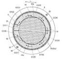
図3は、ベゼルの内側にソーラーパネルを配置した状態を模式的に示す平面図である。なお、図3は模式的なイメージ図であり、後述する各ブロックを分ける線の位置や細線発電部51aの太さ・本数等は、実際の形状を厳密に再現するものではない。
図3に示すように、本実施形態のソーラーパネル5は、環状部材であるベゼル6の直径方向における中央部の領域である透光発電領域SArと、透光発電領域SArの外周部の領域であって、周方向に沿って複数のソーラーセルCの一部(ソーラーセルCを構成するブロック)が配置された外周発電領域PArとを備えており、複数のセル(ソーラーセルC)に分割されている。
FIG. 3 is a plan view schematically showing a state in which the solar panel is arranged inside the bezel. Note that FIG. 3 is a schematic image diagram, and the positions of the lines dividing each block, the thickness and the number of the thin wire
As shown in FIG. 3, the
透光発電領域SArは、所定の方向(延在方向L)に延在する細線状の発電部51である細線発電部51aが延在方向Lに直交する方向に並列配置された領域である。透光発電領域SArでは細線発電部51aと光を透過させる透過領域52とが交互に一定のピッチで配列されている。
本実施形態では、ソーラーセルCのうち、少なくとも外部から視認される前述の視認領域VArに対応して配置される部分が、透光発電領域SArとして構成される。
The translucent power generation region SAr is a region in which the thin wire
In the present embodiment, of the solar cell C, at least the portion arranged corresponding to the above-mentioned visible area VAr visually recognized from the outside is configured as the translucent power generation area SAr.
透光発電領域SAr内に配置される細線発電部51aのピッチを揃えることで、外部から表示部4を目視した際に、ソーラーセルCが表示部4よりも上側(視認側、表面側)に配置されていても面全体として均一の明るさになるため細線発電部51aが目立たず、表示部4の視認性がよく、見栄えのよい外観を実現することができる。
なお、実施形態において、単に「発電部51」と記載したときは、細線発電部51a及びこれ以外の発電部51の両方を含むものとする。
By aligning the pitches of the thin wire
In the embodiment, when the term "
ソーラーパネル5における発電部51は、図示しない基材の上に透過電極、半導体層、裏面電極(いずれも図示せず)が順に積層された積層構造となっている。
基材は、光透過性を有する薄板状の基板であり、例えばフレキシブルなフィルム状の透過プラスチック等である。基材を形成する材料はここに例示したものに限定されないが、例えば各種の透明な樹脂、ガラス等が適用される。
また、透過電極は、例えば、酸化亜鉛、酸化インジウム、酸化スズ等を結晶化させることで形成されている。なお、透過電極を形成する材料や形成手法はこれに限定されない。
半導体層は、例えばアモルファスシリコン(a-Si:H)等で形成されている。半導体層としては、例えばp型半導体とn型半導体とが接合されたpn接合型の半導体が用いられる。
裏面電極は、例えばアルミニウム導体等の金属材料を含んで形成されている。なお、裏面電極を形成する材料はこれに限定されない。
半導体層や裏面電極は、例えば、基材の上に蒸着等の手法により積層形成される。なお、基材上に半導体層や裏面電極を設ける手法はこれに限定されない。
The
The base material is a thin plate-shaped substrate having light transmittance, for example, a flexible film-shaped transparent plastic or the like. The material forming the base material is not limited to those exemplified here, and for example, various transparent resins, glass, and the like are applied.
Further, the transmission electrode is formed by crystallizing, for example, zinc oxide, indium oxide, tin oxide and the like. The material and method for forming the transmission electrode are not limited to this.
The semiconductor layer is formed of, for example, amorphous silicon (a-Si: H) or the like. As the semiconductor layer, for example, a pn junction type semiconductor in which a p-type semiconductor and an n-type semiconductor are bonded is used.
The back surface electrode is formed to include a metal material such as an aluminum conductor. The material forming the back surface electrode is not limited to this.
The semiconductor layer and the back surface electrode are laminated and formed on the substrate by, for example, a method such as thin film deposition. The method of providing the semiconductor layer and the back surface electrode on the base material is not limited to this.
発電部51のうち、透光発電領域SAr内に配置される細線発電部51aの細さ(延在方向Lに直交する幅方向の寸法)は特に限定されないが、例えば、透過領域52の細さ(延在方向Lに直交する幅方向の寸法)が70μm程度であるときに、10μm程度である。
なお、細線発電部51aの幅を小さく(細く)し、透過領域52の幅を大きく(太く)するほどソーラーパネル5の透光発電領域SArにおける光の透過度が高くなり表示部4の視認領域VArの視認性が向上する。一方で細線発電部51aの幅が小さくなるほど発電量が少なくなるとともにソーラーセルC内を電荷が移動する際の抵抗が大きくなり発電効率が低下する。
このため、細線発電部51aの幅及び透過領域52の幅は、表示部4の視認領域VArに求められる視認性の程度(すなわち、視認領域VArに対応して設けられる透光発電領域SArの光透過性の程度)とソーラーパネル5に求められる発電量、発電効率の程度との兼ね合いから適宜設定される。
Of the
The smaller (thinner) the width of the thin wire
Therefore, the width of the thin wire
また、外周発電領域PArは、透光発電領域SArの外周を取り囲むように設けられた環状の領域である。
本実施形態では、外周発電領域PArは、周方向に沿って8つのブロックに分割されている。
各ブロックは、ほぼ扇型形状となっており、それぞれがソーラーセルC(ソーラーセルC1~C8)を構成している。
Further, the outer peripheral power generation region PAr is an annular region provided so as to surround the outer periphery of the translucent power generation region SAr.
In the present embodiment, the outer peripheral power generation region PAr is divided into eight blocks along the circumferential direction.
Each block has a substantially fan-shaped shape, and each constitutes a solar cell C (solar cells C1 to C8).
ソーラーパネル5は、ソーラーセルC同士を直列に電気的に接続する図示しない接続部を有している。本実施形態では、外周発電領域PArに、各ブロックを接続する接続部が設けられており、各ブロックが接続されることで各ソーラーセルCが一体としてソーラーパネル5を構成するようになっている。
本実施形態において、接続部は、前述の視認領域VArよりも外側に配置され、外部から視認されないようになっている。
なお、ソーラーセルCは、図3において太線矢印で示すように、アンテナとして機能する環状部材であるベゼル6の周方向に沿って電荷が移動するように外周発電領域PArに配置されるソーラーセルC(ブロック部分)が接続されていることが好ましい。
また、ソーラーパネル5は、2つの端子部55を備えている。一方側の端子部55は、モジュール等に設けられた図示しない基板上の+電極と電気的に接続され、他方側の端子部55は、基板上の-電極と電気的に接続される。
端子部55の配置は特に限定されないが、図3ではソーラーセルC1とソーラーセルC8の端部にそれぞれ配置されている例を示している。
The
In the present embodiment, the connection portion is arranged outside the above-mentioned visible area VAr so as not to be visually recognized from the outside.
As shown by the thick arrow in FIG. 3, the solar cell C is arranged in the outer peripheral power generation region PAr so that the electric charge moves along the circumferential direction of the
Further, the
The arrangement of the
ソーラーパネル5がいくつのセル(ソーラーセルC)で構成されるかは特に限定されない。図3では、8つのセルC(図3においてソーラーセルC1~C8)を直列接続してソーラーパネル5が構成される例を示している。
直列接続されるソーラーセルCの数が多いほどソーラーパネル5全体としての電圧が高くなる。このため、ソーラーパネル5を構成するソーラーセルCの数は、ソーラーパネル5によって発電された発電電力を蓄える二次電池の電圧等、必要とされる電圧レベルに応じて適宜設定されることが好ましい。
The number of cells (solar cell C) in which the
As the number of solar cells C connected in series increases, the voltage of the entire
複数のソーラーセルC1~C8のうち、少なくとも一部のソーラーセルCは、外周発電領域PArの少なくとも一部分(外周発電領域PArを構成するブロック部分)と透光発電領域SArの少なくとも一部分とを含んで構成される複合セルとなっている。
複合セルにおいては、透光発電領域SArが外周発電領域PArの部分を介してソーラーセルCの一部分として機能するようになっており、透光発電領域SArは、ベゼル6の直径方向における一端側で外周発電領域PArを構成するいずれかのブロック(ソーラーセルCを構成するブロック部分)と接続されている。
本実施形態では、透光発電領域SArが延在方向Lに沿う分割線によって図3における上下2つの領域に分割されている。そして、ソーラーセルC1が外周発電領域PArのブロックの他に透光発電領域SArの上側のほぼ半分を含んでおり、ソーラーセルC8が外周発電領域PArのブロックの他に透光発電領域SArの下側のほぼ半分を含んでいる。
なお、図3ではソーラーセルC1及びソーラーセルC8の範囲を太破線で囲んで示している。
Of the plurality of solar cells C1 to C8, at least a part of the solar cells C includes at least a part of the outer peripheral power generation area PAr (a block portion constituting the outer peripheral power generation area PAr) and at least a part of the translucent power generation area SAr. It is a composite cell that is composed.
In the composite cell, the translucent power generation region SAr functions as a part of the solar cell C via the portion of the outer peripheral power generation region PAr, and the translucent power generation region SA is located at one end side in the radial direction of the
In the present embodiment, the photovoltaic power generation region SAr is divided into two upper and lower regions in FIG. 3 by a dividing line along the extending direction L. Then, the solar cell C1 includes the upper half of the translucent power generation region SA in addition to the block of the outer peripheral power generation region PAr, and the solar cell C8 is below the translucent power generation region SA in addition to the block of the outer peripheral power generation region PAr. Includes almost half of the side.
In FIG. 3, the range of the solar cell C1 and the solar cell C8 is shown by being surrounded by a thick broken line.
なお、本実施形態のソーラーパネル5は、環状部材であるベゼル6の直径方向における一端側に複数のソーラーセルCのうちの所定のセルが配置され、直径方向の他端側には、複数のソーラーセルCのうちの所定のソーラーセルCとは異なるソーラーセルCが配置されるように構成される。
例えば、透光発電領域SArの一部を含むソーラーセルC1は、一端側が図3におけるソーラーパネル5の左側端部に配置されているが、他端側の端部にはソーラーセルC4、C5が配置されている。同様に、透光発電領域SArの一部を含むソーラーセルC8は、一端側が図3におけるソーラーパネル5の左側端部に配置されているが、他端側の端部にはソーラーセルC5、C6が配置されている。また、ソーラーセルC6は、一端側が図3におけるソーラーパネル5の下側端部に配置されているが、他端側の端部にはソーラーセルC2が配置されている。
これにより、1つのソーラーセルCが、ベゼル6の直径方向における一端側から他端側までかけ渡された状態とならないようになっている。
In the
For example, the solar cell C1 including a part of the translucent power generation region SA has one end side arranged at the left end portion of the
As a result, one solar cell C is prevented from being stretched from one end side to the other end side in the diameter direction of the
なお、複数のソーラーセルCを直列接続して1つのソーラーパネル5を構成する場合、各ソーラーセルC間の出力電流値に差が生じると、ソーラーパネル5の出力電流値は各ソーラーセルCのうち最も出力電流値の小さいソーラーセルCに合せて小さくなってしまう。
このため、発電効率を上げるために、各ソーラーセルCは、各セルにおける発電部51の面積ができるだけ等しくなるように構成することが好ましい。
本実施形態では、図3に示すように、透光発電領域SArの一部を含んでいるソーラーセルC1,C8の外周発電領域PArのブロックの面積は他のブロックよりも小さく、外周発電領域PArのブロックのみで構成されるソーラーセルC2~C7ではブロックの面積はほぼ等しくなるようにすることで、ソーラーセルC1~C8の発電部51の面積がほぼ等しくなるように調整されている。
When a plurality of solar cells C are connected in series to form one
Therefore, in order to increase the power generation efficiency, it is preferable that each solar cell C is configured so that the areas of the
In the present embodiment, as shown in FIG. 3, the area of the outer peripheral power generation region PAr of the solar cells C1 and C8 including a part of the translucent power generation region SAr is smaller than the other blocks, and the outer peripheral power generation region PAr. In the solar cells C2 to C7 composed of only the blocks of the above, the areas of the blocks are made to be substantially equal, so that the areas of the
なお、例えば装飾部の一部に金属パーツで形成されたロゴマーク等を設ける等、発電部51の一部が光透過性の低い部材等で覆われるような場合、光透過性が低くなった部分の発電部51の発電量が低下する。
この場合には、ソーラーパネル5の外周部のなるべく外観に影響しない部分におけるソーラーセルCの形状を微調整する等、目立たない箇所において各ソーラーセルCの面積を調整して各ソーラーセルCにおける発電量を揃えることが好ましい。
In addition, when a part of the
In this case, the area of each solar cell C is adjusted in an inconspicuous place, such as finely adjusting the shape of the solar cell C in the outer peripheral portion of the
次に、本実施形態におけるソーラーパネル5及びこれを備える電子機器としての時計100の作用について説明する。
本実施形態においてソーラーパネル5は、時計100の視認側に配置されたベゼル6の内側に配置される。また、ソーラーパネル5の下側には、表示部4が配置される。
このとき、表示部4の視認領域VArに透光発電領域SArが対応するようにソーラーパネル5を配置する。
透光発電領域SArは、細線発電部51aと透過領域52の長手方向をそろえて配列することで構成されている。このため、表示部4の上側にソーラーパネル5を配置しても表示部4の視認性が損なわれないとともに、表示部4の上側にも発電部51(細線発電部51a)を確保できるため、表示部4の外周部にのみ発電部51を配置する場合に比べて、発電量を増大させることができる。
Next, the operation of the
In the present embodiment, the
At this time, the
The translucent power generation region SAr is configured by arranging the thin wire
本実施形態では、ベゼル6がアンテナとして機能するが、本実施形態に示すソーラーパネル5をベゼル6の内側に配置した場合にも、ベゼル6のアンテナ特性に影響を及ぼさず、所望の周波数の電波を良好に受信することができる。
ここで、本実施形態におけるソーラーパネル5がアンテナとしてのベゼル6の特性に影響を与えないことについて図4(a)、図4(b)及び図5を用いて説明する。
In the present embodiment, the
Here, it will be described with reference to FIGS. 4 (a), 4 (b) and 5 that the
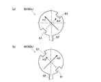
図4(a)及び図4(b)は、一点給電方式の通常の円形パッチアンテナの例における第1モードの電流の経路と第2モードの電流の経路とを示す説明図であり、図5は、第1モード及び第2モードの共振特性を比較した図である。
本実施形態においてアンテナとして機能するベゼル6は前述のとおり環状に形成されているが、アンテナとしての構成は、図4(a)及び図4(b)に例示するような円形のパッチアンテナの中央部を抜いたものと同様に考えることができる。
このため、まず、図4(a)、図4(b)及び図5を参照しつつ、本実施形態におけるベゼル6によって円偏波が生成される考え方について説明する。
4 (a) and 4 (b) are explanatory views showing the current path of the first mode and the current path of the second mode in the example of the ordinary circular patch antenna of the one-point feeding system, and FIG. Is a figure comparing the resonance characteristics of the first mode and the second mode.
The
Therefore, first, with reference to FIGS. 4 (a), 4 (b), and FIG. 5, the concept of generating circularly polarized waves by the
図4(a)及び図4(b)に示すように、アンテナ(アンテナ素子)60の一部に切込み61を形成した場合、互いに直交する2つの電流(第1モードM1の電流及び第2モードM2の電流)がアンテナ(アンテナ素子)60上に励振される。
切込み61を設けることで、アンテナ(アンテナ素子)60にアンバランスを生じ、切込み61が設けられた側を流れる第2モードM2の電流の電流経路m2(図4(a)及び図4(b)において破線で示す。)は、切込み61が設けられていない側を流れる第1モードM1の電流の電流経路m1(図4(a)及び図4(b)において実線で示す。)と比べて短くなる。
このため、第1モードM1及び第2モードM2の共振特性を比較すると、図5に示すように、第1モードM1の共振周波数f1は、第2モードM2の共振周波数f2よりも低くなる。ここで、2つのモードの共振特性が共振時の振幅に対して倍となる周波数f0で交点を持つように切込み61の面積が設定されるとf0における第1モードM1と第2モードM2間の位相差はπ/2前後の値となる。これらのモードを波源とする放射界が空間的に合成されることにより円偏波が生成される。
As shown in FIGS. 4A and 4B, when a
By providing the
Therefore, when the resonance characteristics of the first mode M1 and the second mode M2 are compared, as shown in FIG. 5, the resonance frequency f1 of the first mode M1 is lower than the resonance frequency f2 of the second mode M2. Here, when the area of the
そして、図4(a)のような配置で切込み61を設けたアンテナ(アンテナ素子)60aの場合には、右旋偏波が放射され、図4(b)のように図4(a)に示す場合に対して、給電点62に対して対称な位置に切込み61を設けたアンテナ(アンテナ素子)60bの場合には、左旋偏波が放射される。
本実施形態のベゼル6においても同様の考え方に基づき、所望の円偏波(例えばGPS電波を受信したい場合には右旋円偏波)を発生させるように、各部の形状等が調整されている。
Then, in the case of the antenna (antenna element) 60a provided with the
In the
この場合に、ベゼル6の内側にソーラーパネルが配置された場合、当該ソーラーパネルが例えば線状発電部51aの延在方向Lに沿ってベゼル6の直径方向における一端側から他端側に亘って短冊状のソーラーセルに分割されていると、ベゼル6において調整、設定されているバランス(所望の円偏波を発生させるために設定されているバランス)を崩してしまうおそれがある。
すなわち、上記のような短冊状のソーラーセルでは、線状発電部51aの延在方向Lに沿って電荷が移動し、電流の流れる方向が強固に決定される。このため、線状発電部51aの設けられている透光発電領域SArが延在方向Lに沿って、ベゼル6の直径方向の一端側から他端側に亘って設けられると、環状のベゼル6が透光発電領域SAr(ソーラーパネル)と容量結合するおそれがある。この場合ベゼル6における直径方向の一端側と他端側とが透光発電領域SAr(ソーラーパネル)を介して接続されたのと同様の状態となると考えられる。
このため、所望の周波数に合う円偏波を発生するように調整されたベゼル6のバランス(すなわち、上記の第1モードM1の電流の電流経路m1と第2モードM2の電流の電流経路m2としてベゼル6に設定されている、所望の円偏波を発生させるためのバランス)が崩れて所望の周波数の電波を受信することができなくなる可能性がある。また、ベゼル6が透光発電領域SAr(ソーラーパネル)と容量結合すると、透光発電領域SArを通る電流経路が生じ、この経路を電流が流れることによって発生する損失によって利得の低下が起きてしまうおそれもある。
In this case, when the solar panel is arranged inside the
That is, in the strip-shaped solar cell as described above, the electric charge moves along the extending direction L of the linear
Therefore, as the balance of the
この点、本実施形態のソーラーパネル5では、線状発電部51aの設けられている透光発電領域SArがベゼル6の直径方向の一端側から他端側に亘って設けられることがないように構成されているため、上記のようなおそれを生じない。
In this respect, in the
本実施形態のソーラーパネル5を時計100に適用した場合には、時計100の視認側であって表示部4の上側にソーラーパネル5を配置することで、風防部材3を介して光が入射した際、ソーラーセルC1~C8の発電部51において効率よく光発電が行われる。各ソーラーセルCは接続部で接続されて1つのソーラーパネル5として構成され、ソーラーパネル5全体としての発電により得られた電力は二次電池に蓄えられる。そして、二次電池からモジュールのモータ等の各種動作部に十分な電力が供給されて時計100が駆動する。
また、アンテナとして機能するベゼル6が受信したGPS電波等に基づいて適宜時刻情報や位置情報等の取得等が行われる。
When the
Further, time information, position information, and the like are appropriately acquired based on the GPS radio wave or the like received by the
以上のように、本実施形態によれば、所望の周波数の電波と共振するように構成されたベゼル6の近傍に配置され複数のソーラーセルCに分割されたソーラーパネル5が、ベゼル6の直径方向における中央部の領域であって、所定の方向に延在する細線発電部51aが延在方向に直交する方向に並列配置された透光発電領域SArと、透光発電領域SArの外周部の領域であって、周方向に沿って複数のソーラーセルCの一部が配置された外周発電領域PArと、を備えており、複数のソーラーセルCは、外周発電領域PArの少なくとも一部分(外周発電領域PArを構成するブロック)と透光発電領域SArの少なくとも一部分とを含んで構成される複合セルを含み、ベゼル6の直径方向における一端側に複数のソーラーセルCのうちの所定のソーラーセルCが配置され、直径方向の他端側には、複数のソーラーセルCのうち所定のソーラーセルCとは異なるソーラーセルCが配置されている。
このため、透光発電領域SArを表示部4の視認領域VArに対応する位置に配置することで表示部4の視認性を確保しつつ、視認領域VArに対応する部分でも発電を行うことができることで発電量を増大させることができる。
そして、このような透光発電領域SArを有するソーラーパネル5をアンテナとして機能するベゼル6の近傍(本実施形態ではベゼル6の内側)に配置した場合でも、アンテナ特性に影響を与えず、良好な受信状態を維持することが可能となる。
As described above, according to the present embodiment, the
Therefore, by arranging the translucent power generation area SAr at a position corresponding to the visible area VAr of the
Even when the
また、本実施形態では、複合セルの外周発電領域の部分を介して、透光発電領域SArは、ベゼル6の直径方向における一端側で外周発電領域PArを構成するいずれかのブロック(ソーラーセルCを構成するブロック部分)と接続される。
これにより、透光発電領域SArから効率よく電荷を取り出すことができる。また、透光発電領域SArがベゼル6の直径方向の一端側から他端側に亘って設けられることがなく、ベゼル6がアンテナとして機能する場合にそのアンテナ特性に影響を及ぼさない。
Further, in the present embodiment, the translucent power generation region SA is one of the blocks (solar cell C) constituting the outer peripheral power generation region PAr on one end side in the radial direction of the
As a result, electric charges can be efficiently extracted from the photovoltaic power generation region SA. Further, the photovoltaic power generation region SA is not provided from one end side to the other end side in the radial direction of the
また、本実施形態では、透光発電領域SArは、細線発電部51aの延在方向に沿って分割される。
このため、ユーザが外部から視認した際に、分割部分が目立ちにくく、良好な外観を維持することができる。
Further, in the present embodiment, the photovoltaic power generation region SAr is divided along the extending direction of the thin wire
Therefore, when the user visually recognizes it from the outside, the divided portion is inconspicuous and a good appearance can be maintained.
また、本実施形態では、ソーラーパネル5を構成する各ソーラーセルCは、同じ発電量となるように均等に分割されている。
これにより、ソーラーセルC間の出力電流値の差異を小さくすることができ、ソーラーパネル5全体としての出力電流値を最大限とすることができ、発電効率を向上させることができる。
Further, in the present embodiment, each solar cell C constituting the
As a result, the difference in the output current value between the solar cells C can be reduced, the output current value of the entire
また、本実施形態では、外周発電領域PArに配置されるソーラーセルC(ソーラーセルCを構成するブロック)は、アンテナとして機能するベゼル6の周方向に沿って電荷が移動するように接続されている。
これにより、ソーラーパネル5によるベゼル6への影響を小さく抑えることが期待できる。
Further, in the present embodiment, the solar cell C (block constituting the solar cell C) arranged in the outer peripheral power generation region PAr is connected so that the electric charge moves along the circumferential direction of the
As a result, it can be expected that the influence of the
なお、以上本発明の実施形態について説明したが、本発明は、かかる実施形態に限定されず、その要旨を逸脱しない範囲で、種々変形が可能であることは言うまでもない。 Although the embodiments of the present invention have been described above, it goes without saying that the present invention is not limited to such embodiments and can be variously modified without departing from the gist thereof.
例えば、透光発電領域SArは、2つに分割する場合に限定されない。
図6に示すように、ソーラーパネル501において、透光発電領域SArを分割せずに外周発電領域PArの1つのソーラーセルC(ソーラーセルCを構成する1つのブロック)と接続させて、ソーラーセルC11としてもよい。
この場合には、ソーラーセルC11ですべての透光発電領域SArを受け持つ分、外周発電領域PArのブロック部分のうち透光発電領域SArと接続されるブロック部分の面積を他のブロック部分の面積よりも小さくするように調整して各ソーラーセルCの面積がほぼ均等となるようにする。
このように、透光発電領域SArを分割しないことで、ソーラーパネル501の構成をよりシンプルにすることができる。
For example, the photovoltaic power generation region SA is not limited to the case where it is divided into two.
As shown in FIG. 6, in the
In this case, since the solar cell C11 is in charge of all the translucent power generation area SA, the area of the block part connected to the translucent power generation area SA of the block part of the outer peripheral power generation area PAr is larger than the area of the other block parts. Adjust so that the area of each solar cell C is almost equal.
By not dividing the translucent power generation region SA in this way, the configuration of the
また、図7に示すように、ソーラーパネル502を構成する透光発電領域SArを、複数(例えば図7では2つ)に分割した場合に、各複合セルにおける外周発電領域PArのブロック部分(分割された各透光発電領域SArと接続される外周発電領域PArの部分)をベゼル6の環状中心に対して点対称位置にそれぞれ配置してもよい。
このように、透光発電領域SArを複数(本実施形態では2つ)に分割した場合に、複合セルを構成する外周発電領域PArのブロック部分がベゼル6の環状中心に対して点対称位置に配置されるようにすることで、ソーラーパネル5の周囲に配置されるベゼル6の、アンテナとしての機能を発揮するためのバランスに、より悪影響を及ぼしにくくなる。
なお、透光発電領域SArをいくつに分割して外周発電領域PArのいくつのブロック部分で分担し複合セルを構成するかは、適宜設定される。
Further, as shown in FIG. 7, when the translucent power generation region SAr constituting the
In this way, when the translucent power generation region SAr is divided into a plurality of (two in the present embodiment), the block portion of the outer peripheral power generation region PAr constituting the composite cell is at a point-symmetrical position with respect to the annular center of the
It should be noted that how many blocks of the photovoltaic power generation area SAr are divided and how many blocks of the outer peripheral power generation area PAr are shared to form a composite cell are appropriately set.
また、ソーラーパネル5の形状は、上記実施形態に示したほぼ円形状のものに限定されない。
例えば、楕円形状等でもよいし、多角形状等でもよい。
Further, the shape of the
For example, it may be an elliptical shape or the like, or it may be a polygonal shape or the like.
さらに、ソーラーパネル5を構成する各ソーラーセルCの形状も、上記実施形態に示したものに限定されない。
Further, the shape of each solar cell C constituting the
また、本実施形態では、細線発電部51aが一定の方向Lに沿って延在する細い直線状に形成された発電部51である場合を例示したが、細線発電部51aの形状はこれに限定されない。
例えば、細線発電部51aは同心円状や渦巻き形状、放射線状等に形成されていてもよい。
この場合にも細線発電部51aを含む透光発電領域SArの周囲に外周発電領域PArを配置し、外周発電領域PArを構成するいずれかのブロックを透光発電領域SArに接続して、細線発電部51aによって発生した電荷を回収可能な構成とする。
Further, in the present embodiment, the case where the thin wire
For example, the thin wire
Also in this case, the outer peripheral power generation area PAr is arranged around the translucent power generation area SA including the thin wire
また、本実施形態では、環状に形成されたベゼル6がアンテナとして機能し、このベゼル6の内側にソーラーパネル5を配置する場合を例示したが、アンテナの形状や配置、ソーラーパネル5とアンテナとの位置関係はこれに限定されない。
例えば、アンテナは、ソーラーパネル5の上方又は下方に配置されていてもよい。
ソーラーパネル5を本実施形態に示したような構成とすることで、アンテナがソーラーパネル5の上方や下方等に配置された場合にも、アンテナとソーラーパネル5とが容量結合しにくく、アンテナ特性に影響を与えず、良好な受信状態を維持することが可能となる。
Further, in the present embodiment, the case where the
For example, the antenna may be located above or below the
By configuring the
また、本実施形態では、ソーラーパネル5を時計100に組み込む場合を例示したが、ソーラーパネル5を組み込む電子機器は時計100に限定されない。
ソーラーパネル5により発電を行い、発電された電力を駆動源として動作する機器であれば広く適用することが可能であり、例えば、歩数計、心拍計や脈拍計等の生体情報表示装置、移動距離や移動ペース情報、高度情報や気圧情報等の各種の情報を表示させる各種の電子機器等であってもよい。
Further, in the present embodiment, the case where the
Any device that generates electricity with the
以上本発明のいくつかの実施形態を説明したが、本発明の範囲は、上述の実施の形態に限定するものではなく、特許請求の範囲に記載された発明の範囲とその均等の範囲を含む。
以下に、この出願の願書に最初に添付した特許請求の範囲に記載した発明を付記する。付記に記載した請求項の項番は、この出願の願書に最初に添付した特許請求の範囲の通りである。
〔付記〕
<請求項1>
所望の周波数の電波と共振するように構成された環状部材の近傍に配置され、複数のセルに分割されたソーラーパネルであって、
前記環状部材の直径方向における中央部の領域であって、所定の方向に延在する細線状の発電部が延在方向に直交する方向に並列配置された透光発電領域と、
前記透光発電領域の外周部の領域であって、周方向に沿って前記複数のセルの一部が配置された外周発電領域と、
を備え、
前記複数のセルは、前記外周発電領域の少なくとも一部分と前記透光発電領域の少なくとも一部分とを含んで構成される複合セルを含み、
前記環状部材の直径方向における一端側に前記複数のセルのうちの所定のセルが配置され、前記直径方向の他端側には前記複数のセルのうち前記所定のセルとは異なるセルが配置されていることを特徴とするソーラーパネル。
<請求項2>
前記複合セルの前記外周発電領域の部分を介して、前記透光発電領域は、前記環状部材の直径方向における一端側で前記外周発電領域を構成するいずれかの前記セルと接続されることを特徴とする請求項1に記載のソーラーパネル。
<請求項3>
前記透光発電領域は、少なくとも2つに分割され、
2つの前記複合セルの前記外周発電領域の部分は、前記環状部材の環状中心に対して点対称位置にそれぞれ配置されることを特徴とする請求項1又は請求項2に記載のソーラーパネル。
<請求項4>
前記透光発電領域は、前記細線状の発電部の延在方向に沿って分割されることを特徴とする請求項3に記載のソーラーパネル。
<請求項5>
前記セルは、同じ発電量となるように均等に分割されていることを特徴とする請求項1から請求項4のいずれか一項に記載のソーラーパネル。
<請求項6>
前記外周発電領域に配置される前記セルは、アンテナとして機能する前記環状部材の周方向に沿って電荷が移動するように接続されていることを特徴とする請求項1から請求項5のいずれか一項に記載のソーラーパネル。
<請求項7>
請求項1から請求項6のいずれか一項に記載のソーラーパネルと、
前記ソーラーパネルの外周に配置され、所望の周波数の電波と共振するように構成された環状のベゼルと、
を備えることを特徴とする電子機器。
<請求項8>
請求項1から請求項6のいずれか一項に記載のソーラーパネルと、
前記ソーラーパネルの外周に配置され、所望の周波数の電波と共振するように構成された環状のベゼルと、
を備えることを特徴とする電子時計。
Although some embodiments of the present invention have been described above, the scope of the present invention is not limited to the above-described embodiments, but includes the scope of the invention described in the claims and the equivalent scope thereof. ..
The inventions described in the claims originally attached to the application of this application are described below. The claims described in the appendix are the scope of the claims originally attached to the application for this application.
[Additional Notes]
<Claim 1>
A solar panel arranged in the vicinity of an annular member configured to resonate with a radio wave of a desired frequency and divided into a plurality of cells.
A photovoltaic power generation region, which is a central region in the diameter direction of the annular member and in which thin linear power generation portions extending in a predetermined direction are arranged in parallel in a direction orthogonal to the extending direction.
An outer peripheral power generation region in which a part of the plurality of cells is arranged along the circumferential direction, which is a region of the outer peripheral portion of the translucent power generation region.
Equipped with
The plurality of cells include a composite cell configured to include at least a part of the peripheral power generation area and at least a part of the photovoltaic power generation area.
A predetermined cell among the plurality of cells is arranged on one end side in the radial direction of the annular member, and a cell different from the predetermined cell among the plurality of cells is arranged on the other end side in the radial direction. A solar panel characterized by being.
<Claim 2>
Through the portion of the outer peripheral power generation region of the composite cell, the translucent power generation region is connected to any of the cells constituting the outer peripheral power generation region on one end side in the radial direction of the annular member. The solar panel according to
<Claim 3>
The photovoltaic power generation area is divided into at least two parts.
The solar panel according to
<Claim 4>
The solar panel according to
<Claim 5>
The solar panel according to any one of
<Claim 6>
One of
<Claim 7>
The solar panel according to any one of
An annular bezel located on the outer periphery of the solar panel and configured to resonate with radio waves of a desired frequency.
An electronic device characterized by being equipped with.
<Claim 8>
The solar panel according to any one of
An annular bezel located on the outer periphery of the solar panel and configured to resonate with radio waves of a desired frequency.
An electronic clock characterized by being equipped with.
4 表示部
5 ソーラーパネル
6 ベゼル
51 発電部
52 透過領域
100 時計
C ソーラーセル
L 延在方向
PAr 外周発電領域
SAr 透光発電領域
VAr 視認領域
4
Claims (8)
前記環状部材の直径方向における中央部の領域であって、所定の方向に延在する細線状の発電部が延在方向に直交する方向に並列配置された透光発電領域と、
前記透光発電領域の外周部の領域であって、周方向に沿って前記複数のセルの一部が配置された外周発電領域と、
を備え、
前記複数のセルは、前記外周発電領域の少なくとも一部分と前記透光発電領域の少なくとも一部分とを含んで構成される複合セルを含み、
前記環状部材の直径方向における一端側に前記複数のセルのうち前記複合セルが配置され、前記直径方向の他端側には前記複数のセルのうち前記外周発電領域で構成され前記透光発電領域を含まないセルが配置されていることを特徴とするソーラーパネル。 A solar panel arranged in the vicinity of an annular member configured to resonate with a radio wave of a desired frequency and divided into a plurality of cells.
A photovoltaic power generation region, which is a central region in the diameter direction of the annular member and in which thin linear power generation portions extending in a predetermined direction are arranged in parallel in a direction orthogonal to the extending direction.
An outer peripheral power generation region in which a part of the plurality of cells is arranged along the circumferential direction, which is a region of the outer peripheral portion of the translucent power generation region.
Equipped with
The plurality of cells include a composite cell configured to include at least a part of the peripheral power generation area and at least a part of the photovoltaic power generation area.
The composite cell of the plurality of cells is arranged on one end side in the radial direction of the annular member, and the outer peripheral power generation region of the plurality of cells is formed on the other end side in the radial direction. A solar panel characterized by the placement of cells that do not contain .
2つの前記複合セルの前記外周発電領域の部分は、前記環状部材の環状中心に対して点対称位置にそれぞれ配置されることを特徴とする請求項1又は請求項2に記載のソーラーパネル。 The photovoltaic power generation area is divided into at least two parts.
The solar panel according to claim 1 or 2, wherein the portions of the outer peripheral power generation region of the two composite cells are arranged at point-symmetrical positions with respect to the annular center of the annular member, respectively.
前記ソーラーパネルの外周に配置され、所望の周波数の電波と共振するように構成された環状のベゼルと、
を備えることを特徴とする電子機器。 The solar panel according to any one of claims 1 to 6, and the solar panel.
An annular bezel located on the outer periphery of the solar panel and configured to resonate with radio waves of a desired frequency.
An electronic device characterized by being equipped with.
前記ソーラーパネルの外周に配置され、所望の周波数の電波と共振するように構成された環状のベゼルと、
を備えることを特徴とする電子時計。 The solar panel according to any one of claims 1 to 6, and the solar panel.
An annular bezel located on the outer periphery of the solar panel and configured to resonate with radio waves of a desired frequency.
An electronic clock characterized by being equipped with.
Priority Applications (3)
| Application Number | Priority Date | Filing Date | Title |
|---|---|---|---|
| JP2019188385A JP7078024B2 (en) | 2019-10-15 | 2019-10-15 | Solar panels, electronic devices and electronic clocks |
| US17/070,178 US11799042B2 (en) | 2019-10-15 | 2020-10-14 | Solar panel, electronic device, and electronic timepiece |
| CN202011103583.2A CN112671327B (en) | 2019-10-15 | 2020-10-15 | Solar cell panel, electronic device, and electronic timepiece |
Applications Claiming Priority (1)
| Application Number | Priority Date | Filing Date | Title |
|---|---|---|---|
| JP2019188385A JP7078024B2 (en) | 2019-10-15 | 2019-10-15 | Solar panels, electronic devices and electronic clocks |
Publications (2)
| Publication Number | Publication Date |
|---|---|
| JP2021064700A JP2021064700A (en) | 2021-04-22 |
| JP7078024B2 true JP7078024B2 (en) | 2022-05-31 |
Family
ID=75384112
Family Applications (1)
| Application Number | Title | Priority Date | Filing Date |
|---|---|---|---|
| JP2019188385A Active JP7078024B2 (en) | 2019-10-15 | 2019-10-15 | Solar panels, electronic devices and electronic clocks |
Country Status (3)
| Country | Link |
|---|---|
| US (1) | US11799042B2 (en) |
| JP (1) | JP7078024B2 (en) |
| CN (1) | CN112671327B (en) |
Families Citing this family (1)
| Publication number | Priority date | Publication date | Assignee | Title |
|---|---|---|---|---|
| JP6891914B2 (en) * | 2019-03-26 | 2021-06-18 | カシオ計算機株式会社 | Solar panels, display devices and clocks |
Citations (5)
| Publication number | Priority date | Publication date | Assignee | Title |
|---|---|---|---|---|
| JP2001267603A (en) | 2000-03-21 | 2001-09-28 | Citizen Watch Co Ltd | Electronic equipment and solar cell module |
| JP2003130969A (en) | 2001-10-22 | 2003-05-08 | Citizen Watch Co Ltd | Dial structure for solar timepiece |
| JP2015072251A (en) | 2013-09-04 | 2015-04-16 | カシオ計算機株式会社 | Solar panels and watches |
| US20180261704A1 (en) | 2017-03-13 | 2018-09-13 | Intel Corporation | Monolithic integration of dissimilar photovoltaic layers in wearable devices |
| JP2019086415A (en) | 2017-11-07 | 2019-06-06 | カシオ計算機株式会社 | Electronic clock |
Family Cites Families (6)
| Publication number | Priority date | Publication date | Assignee | Title |
|---|---|---|---|---|
| US6791905B1 (en) * | 1998-11-26 | 2004-09-14 | Citizen Watch Co., Ltd. | Timepiece |
| JP5493527B2 (en) * | 2009-07-14 | 2014-05-14 | セイコーエプソン株式会社 | Clock with wireless function |
| JP6179123B2 (en) * | 2013-02-21 | 2017-08-16 | セイコーエプソン株式会社 | Electronic clock with built-in antenna |
| JP2016519442A (en) | 2013-05-23 | 2016-06-30 | サンパートナー テクノロジーズSunpartner Technologies | Translucent thin-layer photovoltaic monocell |
| JP6119683B2 (en) * | 2014-06-30 | 2017-04-26 | カシオ計算機株式会社 | Electronics |
| US10276925B2 (en) * | 2017-03-29 | 2019-04-30 | Garmin Switzerland Gmbh | Watch with slot antenna configuration |
-
2019
- 2019-10-15 JP JP2019188385A patent/JP7078024B2/en active Active
-
2020
- 2020-10-14 US US17/070,178 patent/US11799042B2/en active Active
- 2020-10-15 CN CN202011103583.2A patent/CN112671327B/en active Active
Patent Citations (5)
| Publication number | Priority date | Publication date | Assignee | Title |
|---|---|---|---|---|
| JP2001267603A (en) | 2000-03-21 | 2001-09-28 | Citizen Watch Co Ltd | Electronic equipment and solar cell module |
| JP2003130969A (en) | 2001-10-22 | 2003-05-08 | Citizen Watch Co Ltd | Dial structure for solar timepiece |
| JP2015072251A (en) | 2013-09-04 | 2015-04-16 | カシオ計算機株式会社 | Solar panels and watches |
| US20180261704A1 (en) | 2017-03-13 | 2018-09-13 | Intel Corporation | Monolithic integration of dissimilar photovoltaic layers in wearable devices |
| JP2019086415A (en) | 2017-11-07 | 2019-06-06 | カシオ計算機株式会社 | Electronic clock |
Also Published As
| Publication number | Publication date |
|---|---|
| US11799042B2 (en) | 2023-10-24 |
| CN112671327A (en) | 2021-04-16 |
| CN112671327B (en) | 2024-10-29 |
| JP2021064700A (en) | 2021-04-22 |
| US20210111292A1 (en) | 2021-04-15 |
Similar Documents
| Publication | Publication Date | Title |
|---|---|---|
| US9891597B2 (en) | Electronic device | |
| US9523963B2 (en) | Electronic timepiece | |
| JP6763415B2 (en) | Solar panels, display devices and clocks | |
| US8562207B2 (en) | Electronic timepiece | |
| JP6119683B2 (en) | Electronics | |
| JP6003937B2 (en) | Electronics | |
| US20120002512A1 (en) | Electronic Timepiece | |
| JP6488548B2 (en) | Electronics | |
| JP2021167847A (en) | Solar panels, display devices and clocks | |
| CN109557801B (en) | Electronic clock | |
| JP2017122739A (en) | Electronic apparatus | |
| JP7107089B2 (en) | electronic clock | |
| JP7078024B2 (en) | Solar panels, electronic devices and electronic clocks | |
| JP6868500B2 (en) | Electronic clock | |
| JP2021141335A (en) | Solar panels, display devices and clocks | |
| JP6575588B2 (en) | Solar panels and electronics | |
| US11520295B2 (en) | Watch having a protective layer covering a power generating unit and an antenna | |
| JP6264987B2 (en) | Electronics | |
| JP6460885B2 (en) | Satellite radio clock | |
| JP2020204619A (en) | Solar panel, display device, and watch | |
| HK1236055A1 (en) | Electronic device |
Legal Events
| Date | Code | Title | Description |
|---|---|---|---|
| A621 | Written request for application examination |
Free format text: JAPANESE INTERMEDIATE CODE: A621 Effective date: 20210104 |
|
| A977 | Report on retrieval |
Free format text: JAPANESE INTERMEDIATE CODE: A971007 Effective date: 20210928 |
|
| A131 | Notification of reasons for refusal |
Free format text: JAPANESE INTERMEDIATE CODE: A131 Effective date: 20211019 |
|
| A521 | Request for written amendment filed |
Free format text: JAPANESE INTERMEDIATE CODE: A523 Effective date: 20211206 |
|
| TRDD | Decision of grant or rejection written | ||
| A01 | Written decision to grant a patent or to grant a registration (utility model) |
Free format text: JAPANESE INTERMEDIATE CODE: A01 Effective date: 20220419 |
|
| A61 | First payment of annual fees (during grant procedure) |
Free format text: JAPANESE INTERMEDIATE CODE: A61 Effective date: 20220502 |
|
| R150 | Certificate of patent or registration of utility model |
Ref document number: 7078024 Country of ref document: JP Free format text: JAPANESE INTERMEDIATE CODE: R150 |