EP3715744B1 - Usine solaire et procédé de transformation - Google Patents
Usine solaire et procédé de transformation Download PDFInfo
- Publication number
- EP3715744B1 EP3715744B1 EP20166861.3A EP20166861A EP3715744B1 EP 3715744 B1 EP3715744 B1 EP 3715744B1 EP 20166861 A EP20166861 A EP 20166861A EP 3715744 B1 EP3715744 B1 EP 3715744B1
- Authority
- EP
- European Patent Office
- Prior art keywords
- solar
- processing chamber
- raw material
- solar plant
- plant
- Prior art date
- Legal status (The legal status is an assumption and is not a legal conclusion. Google has not performed a legal analysis and makes no representation as to the accuracy of the status listed.)
- Active
Links
Images

Classifications
-
- F—MECHANICAL ENGINEERING; LIGHTING; HEATING; WEAPONS; BLASTING
- F24—HEATING; RANGES; VENTILATING
- F24S—SOLAR HEAT COLLECTORS; SOLAR HEAT SYSTEMS
- F24S20/00—Solar heat collectors specially adapted for particular uses or environments
- F24S20/30—Solar heat collectors for heating objects, e.g. solar cookers or solar furnaces
-
- F—MECHANICAL ENGINEERING; LIGHTING; HEATING; WEAPONS; BLASTING
- F24—HEATING; RANGES; VENTILATING
- F24S—SOLAR HEAT COLLECTORS; SOLAR HEAT SYSTEMS
- F24S20/00—Solar heat collectors specially adapted for particular uses or environments
- F24S20/20—Solar heat collectors for receiving concentrated solar energy, e.g. receivers for solar power plants
-
- F—MECHANICAL ENGINEERING; LIGHTING; HEATING; WEAPONS; BLASTING
- F24—HEATING; RANGES; VENTILATING
- F24S—SOLAR HEAT COLLECTORS; SOLAR HEAT SYSTEMS
- F24S23/00—Arrangements for concentrating solar-rays for solar heat collectors
- F24S23/70—Arrangements for concentrating solar-rays for solar heat collectors with reflectors
-
- Y—GENERAL TAGGING OF NEW TECHNOLOGICAL DEVELOPMENTS; GENERAL TAGGING OF CROSS-SECTIONAL TECHNOLOGIES SPANNING OVER SEVERAL SECTIONS OF THE IPC; TECHNICAL SUBJECTS COVERED BY FORMER USPC CROSS-REFERENCE ART COLLECTIONS [XRACs] AND DIGESTS
- Y02—TECHNOLOGIES OR APPLICATIONS FOR MITIGATION OR ADAPTATION AGAINST CLIMATE CHANGE
- Y02E—REDUCTION OF GREENHOUSE GAS [GHG] EMISSIONS, RELATED TO ENERGY GENERATION, TRANSMISSION OR DISTRIBUTION
- Y02E10/00—Energy generation through renewable energy sources
- Y02E10/40—Solar thermal energy, e.g. solar towers
Definitions
- the present invention falls within the field of renewable energies and more particularly of solar energy.
- the invention relates more precisely to the field of concentrated solar energy, in particular in the form of a single reflection solar plant.
- This solar plant can be applied to an industry requiring great thermal powers of between 1 to 100 Megawatts. Such thermal power corresponds to industrial transformation temperatures between 200 and 3500 ° C.
- Solar energy is free, non-polluting and inexhaustible. These advantages have led to the development of technologies for transforming solar energy into electrical and / or heat energy.
- the double reflection solar oven was developed from 1949, to transform the solar energy concentrated by an optical reflection system.
- the optical reflection system is composed of mirrors concentrating the solar rays in thermal energy at very high temperature between 2000 and 4000 ° C or in electricity. This type of installation was initially developed for special and / or scientific applications.
- the objective of the solar oven is to provide an alternative to the production of energy from the combustion of natural fossil fuels. These so-called fossil fuels are more and more expensive and polluting.
- the development of solar cookers can also help to preserve the wood fuel resource, allowing an effective and real fight against deforestation.
- a double reflection solar oven is composed of a parabolic or spherical shaped concentrator which is coated with distorted mirrors to concentrate very strongly, from 2000 to 16000 times, the solar rays.
- the solar rays are concentrated towards a point of convergence called optical focus where we obtain very high temperatures between 2000 and 4000 ° C.
- the concentrator is fixed and exposed all day long, by one or more heliostats, which are planar adjustable mirrors. The heliostats automatically follow the course of the sun throughout the day.
- a solar furnace with simple reflection comprises a set of focusing heliostats, which follow the sun all day long and reflect, by concentrating them, the solar rays towards a boiler containing a heat transfer fluid.
- the coolant can be stored or used to produce steam, the pressure of which is used to operate a turbine driving an alternator.
- the single reflection solar oven concentrates less solar rays than the double reflection oven, the temperature of the focal focus is therefore lower, of the order of 1000 to 2000 ° C.
- the powers directly linked to the reflection surface are much greater and can reach several tens of megawatts.
- the document WO 2014/052902 describes a first example of a double reflection solar oven.
- the solar oven comprises one or more optical reflectors which are in this document of the heliostat type.
- Optical reflectors are organized and oriented to reflect incident sunlight to an optical concentrator.
- the optical concentrator redirects the sun's rays by reflecting them towards a point of convergence.
- the document WO 2014/052902 proposes to position energy absorption means at the level of the point of convergence.
- the energy absorption means can be, on the one hand, of the calorific type using, for example, a heat exchanger system, and / or, on the other hand, of the electromagnetic type using a photovoltaic element.
- the objective is to transform solar energy into thermal and / or electrical energy.
- the document WO 2015/174236 positions at the point of convergence a heat absorber which absorbs the heat energy of reflected and concentrated solar rays.
- the heat energy absorbed is transformed into electrical energy through a complex process involving the combustion of combustible gases resulting from the thermolysis of coal in order to produce water vapor actuating an electric alternator via the rotation of a turbine. .
- the document US 4,706,651 describes a solar plant which includes a chamber for transforming limestone into lime.
- the solar plant has a single reflection reflection system.
- This reflection system concentrates the solar radiation in the direction of an opening made in the transformation chamber.
- the point of convergence is located at the level of a heat absorber which is integral with the ceiling of the chamber.
- the heat absorber consists of a conveyor belt made from small pieces of refractory material. The conveyor belt rotates so that the heat absorber cools continuously.
- an endless screw acts as a conveyor and transports the limestone which gradually turns into lime.
- the transformation of limestone rock into lime or calcium oxide occurs by calcination at a temperature of around 900 ° C according to the following reaction: CaCO 3 mineral or rock ⁇ solid CaO + CO 2 gas
- the conveyor belt of the heat absorber makes it possible to maintain a temperature of around 900 ° C.
- the document US 2015/0307960 describes another solar plant designed for the refining of magnesium.
- Magnesium refining is a magnesium vaporization reaction that takes place at a temperature above 1107 ° C. This threshold temperature corresponds to the boiling point of magnesium.
- the solar plant has a system of concentrating solar rays with simple reflection which includes a mirror that can be oriented according to the course of the sun.
- This solar plant has a transformation chamber equipped with an opening at which the optical convergence point is located.
- Magnesium briquettes are directly irradiated by solar rays through an opening.
- this document describes in an alternative embodiment, a conveyor which brings the magnesium briquettes into the processing chamber.
- the two solar factories known from the state of the art make it possible to extract an element of interest, here calcium oxide or magnesium, from a raw material.
- an element of interest here calcium oxide or magnesium
- the solar plants described by these documents do not allow continuous firing of materials such as brick, ceramic or terracotta which require a gradual rise in temperature.
- the solar plant is characterized in that it comprises at least one heat exchanger which extends between the inlet duct and the outlet duct, so as to transfer the heat energy released by the material transformed during its transit between the transformation chamber and the exit of the solar plant, to the inlet duct in which the raw material passes before transformation.
- the heat exchanger helps generate a gradual rise in temperature within the inlet duct as the raw material approaches the processing chamber.
- the heat exchanger provides a gradual drop in temperature as the transformed material moves away from the transformation chamber.
- Such a solar plant makes it possible to carry out industrial processes which require a gradual rise and / or fall in temperature.
- the solar plant according to the invention makes it possible to industrialize, using renewable energies, industrial processes such as the firing of ceramics, earthenware, bricks, terracotta, etc.
- the heat exchanger optimizes the energy efficiency of the solar plant by transferring the heat energy that is released from the processed material to the inlet duct.
- the direct use of solar energy makes it possible to improve the efficiency of the solar oven, going from 20 to 30% for the production of electricity, to 50% for the solar oven, and to 70 or 75% for a solar plant according to the invention.
- a solar plant has a less consistent reflection system than a solar oven. This also makes it possible to reduce the installation and maintenance costs of a solar plant compared to a solar oven.
- the concentration and diffusion means comprise at least one heat absorber which is arranged at the level of the point of convergence, on the one hand, the heat absorber absorbing the heat energy of the reflected solar rays. , and on the other hand, the at least one heat absorber diffuses the heat energy of the solar rays reflected to the transformation chamber which is placed in contact with the at least one heat absorber.
- the concentration and diffusion means comprise at least one opening made in a wall of the transformation chamber, the reflection system directing the reflected solar rays towards this opening in such a way. in creating a point of convergence located at the opening of the transformation chamber.
- This arrangement makes it possible to obtain a diverging cone which traps and deconcentrates the solar rays inside the transformation chamber. This makes it possible to heat the enclosure of the transformation chamber while avoiding melting the refractory insulators which line the walls of the transformation chamber.
- the transformation chamber comprises at least one gas burner.
- the gas burner makes it possible to adjust the temperature prevailing in the transformation chamber.
- the burner also makes it possible to generate a reducing atmosphere by reducing the supply of combustion air by adding carbon.
- the burner operates on biogas. The solar plant can thus operate on 100% renewable dual energy.
- the solar plant comprises a source of raw material supplying the conveyor, the source of raw material is arranged upstream of an inlet of the processing chamber.
- the reflection system comprises at least one or more optical reflector (s) and / or the reflection system comprises one or more optical concentrators.
- an optical concentrator can be composed of several focusing mirrors fixed on an orientable or fixed frame.
- the solar plant is thermally insulated by an insulating coating.
- the insulating coating helps optimize the energy efficiency of the solar plant.
- the solar plant comprises a succession of heat exchangers arranged at regular intervals between the transformation chamber and the outlet of the solar plant. More precisely, each heat exchanger extending between a first point disposed in the outlet duct and a second point disposed in the inlet duct.
- the present invention relates to a solar plant 1 which directly uses solar energy in order to catalyze / or carry out an industrial process.
- solar plant 1 includes a reflection system 2 configured to reflect, orient and focus incident solar rays 3.
- the reflection system 2 comprises at least one or more optical reflector (s) 4.
- the optical reflector (s) 4 can be orientable (s). This feature makes it possible to follow the course of the sun throughout a day. The efficiency of the solar oven 1 can thus be optimized.
- the optical reflector (s) 4 are formed by focusing heliostats. Furthermore, the reflection system 2 can also integrate one or more optical concentrator (s). To obtain higher temperatures above 3000 ° C. Such a configuration takes up the concept of the solar oven with flat heliostats.
- the reflection system 2 is configured to reflect and orient the incident solar rays 3 in the direction of at least one point of convergence 5.
- the reflection system 2 consists of two sets of reflectors 4. Each set of reflectors 4 respectively reflects the incident solar rays 3 in the direction of an identical point of convergence 5 or of two distinct points of convergence 5.
- the focal point can include temperatures between 1000 ° C and 3500 ° C.
- optical reflector (s) 4 are oriented so as to reflect the incident solar rays 3 towards the point of convergence 5.
- the solar plant 1 comprises means for concentrating and diffusing 6 the solar rays reflected 7 by the reflection system 2.
- the transformation chamber 8 cooperates with the concentrating and diffusing means 6 which diffuse the heat energy of the solar rays. reflect 7 to the transformation chamber 8.
- the concentration and diffusion means 6 comprise at least one heat absorber 60 arranged so as to receive the solar rays 7 reflected by the reflection system 2.
- the at least one heat absorber 60 is arranged at the level of the point of convergence 5.
- the at least one heat absorber 60 absorbs the heat energy of the solar rays reflected 7 by the reflection system 2.
- the heat absorber 60 can be made of a refractory material such as silicon carbide. The refractory material also exhibits heat conducting properties.
- the heat absorber 60 absorbs the heat energy of the reflected solar rays 7.
- the solar plant 1 comprises a transformation chamber 8.
- the transformation chamber 8 is delimited by walls 9.
- the walls 9 define a transformation chamber 8 of quadrangular shape.
- the transformation chamber 8 comprises four side walls 90 parallel two by two.
- the transformation chamber 8 also comprises an upper wall 91 perpendicular to the side walls 90.
- the upper wall 91 is also parallel with a lower wall 92.
- the transformation chamber 8 can take various three-dimensional shapes such as cylindrical, pyramidal, etc.
- the arrangement of the transformation chamber 8 is determined as a function of the organization of the reflection system 2. As illustrated in figures 1 to 3 , the transformation chamber 8 can rest on the ground or be arranged at a determined height from the ground. In particular, the arrangement of the transformation chamber 8 is linked to the position of the point (s) of convergence (s) 5.
- the transformation chamber 8 contributes to the direct use of solar energy in order to catalyze or carry out an industrial process.
- the transformation chamber 8 is placed in contact with at least one heat absorber 60.
- at least one wall 9, 90, 91, 92 of the transformation chamber 8 is at least partially covered by a heat absorber 60.
- the heat absorber 60 is in the form of a panel at least partially covering a wall 9, 90, 91, 92 of the transformation chamber 8.
- At least two side walls 90 are at least partially covered by a heat absorber 60.
- the side walls 90 at least partially integrate a heat absorber 60.
- the arrangement of one or more heat absorber (s) 6 depends on the number of walls 9, 90, 91, 92 of the heat chamber 8 exposed to reflected solar rays 7.
- the transformation chamber 8 is delimited by walls 9, 90, 91, 92 which are made at least partly in a heat conducting material.
- the heat energy captured by the at least one heat absorber 60 is transferred to the transformation chamber 8. This transfer of heat energy causes a rise in temperature of the transformation chamber 8.
- the transformation chamber 8 is similar to “A solar-powered oven”.
- the concentration and diffusion means 6 comprise at least one opening.
- The, at least one opening is formed in a wall 9, 90, 91, 92 of the transformation chamber 8.
- the concentration and diffusion means 6 comprise at least two openings formed respectively in two walls 9, 90, 91, 92 opposite each other.
- the at least one opening is arranged in the lower part of a wall 9, 90, 91, 92 of the transformation chamber 8.
- the reflection system 2 orients the reflected solar rays 7 in the direction of the at least one opening.
- the reflected solar rays 7 thus penetrate into the enclosure of the transformation chamber 8 and create a point of convergence 5 at the opening.
- the dimensions of the opening correspond to the dimensions of the focal focal point.
- the point of convergence 5 creates an optical divergence cone which deconcentrates and diffuses the light within the transformation chamber 8.
- the solar plant 1 can be equipped without structural modifications with one of the two alternatives of implementation of the means of concentration and diffusion 6.
- the transformation chamber 8 comprises at least one gas burner.
- the transformation chamber 8 comprises at least one biogas burner.
- The, at least one gas burner contributes to adjusting the temperature prevailing in the transformation chamber 8.
- the gas burner is supplied via a gas supply system.
- the at least one gas burner can be manual, semi-automatic or automatic. When the burner is automatic, it can be controlled by the management means. Solar plant 1 then operates on totally renewable dual energy.
- the transformation chamber 8 can also include a temperature sensor connected to the management means.
- a temperature sensor connected to the management means.
- the, at least one burner can be used to adjust the temperature of the transformation chamber 8.
- the at least one burner can maintain the transformation chamber 8 at a determined temperature.
- the solar plant 1 also has a conveyor 10.
- the conveyor 10 is shown schematically by arrows through the conduits 14, 17, 21 ( figure 1 and 2 ).
- the conveyor 10 ensures the transport of raw material from the outside of the solar plant 1 to the processing chamber 8.
- the conveyor 10 is arranged passing through the transformation chamber 8.
- the conveyor 10 enters the transformation chamber 8 through an inlet 11.
- the inlet 11 of the transformation chamber 8 can include means of closure 12.
- the closure means 12 can be formed by a door, an airlock, etc.
- the conveyor 10 leaves the processing chamber 8 via an outlet 13.
- the outlet 13 of the processing chamber 8 can comprise closure means 12.
- the closure means 12 can be formed by a door, an airlock etc.
- the closing means 12 can be actuated manually or controlled by the management means.
- the inlet 11 and the outlet 13 of the transformation chamber 8 can be arranged on the same wall 9, 90, 91, 92 of the transformation chamber 8. However, it is also possible to have respectively the inlet 11 and the outlet 13 of the transformation chamber 8 on two separate walls 9, 90, 91, 92.
- the conveyor 10 makes the raw material pass transiently within the transformation chamber 8.
- the passage time of the raw material in the transformation chamber 8 is defined.
- the passage time of the raw material is defined according to the nature of the raw material and the nature of the transformation that is to be obtained.
- the fact of controlling the passage time of the raw material in the transformation chamber 8 makes it possible to industrialize a raw material transformation process.
- the transformation of matter can correspond to a change of physical state such as the melting of a solid, or conversely the solidification of a ductile or raw material such as the firing of ceramic, terracotta, brick. , earthenware.
- a ductile or raw material such as the firing of ceramic, terracotta, brick. , earthenware.
- the firing of earthenware can be less than 2 hours at 1000 ° C.
- These raw ductile materials have the particularity of requiring a gradual rise in temperature to avoid cracking or breaking of the material or of the object that is to be baked.
- the conveyor 10 can be formed by any mechanical, automatic or semi-automatic system which allows the transport of raw material.
- the conveyor 10 can be formed by wagons mounted on rails. Cars and rails can be refractory. In this case, the rails are mounted passing through the transformation chamber 8.
- the solar plant 1 can include means for automatically managing the actuation of the conveyor 10.
- the management means can be formed by a computer having a microprocessor and a memory.
- the microprocessor is then configured to execute a cooking program stored in the memory.
- the cooking program can be configured by a user through a conventional interface.
- the duration of exposure to heat of the raw material in the processing chamber 8 depends on the temperature prevailing in the processing chamber 8 and on the speed of the conveyor 10.
- the temperature of the processing chamber 8 depends on it, of several factors such as the concentration rate of the reflected solar rays, the absorption coefficient of the raw material etc.
- the conveyor 10 can be supplied with energy by a source of electrical energy.
- Electrical energy can come from a renewable electrical energy source such as solar cells or an electrical distribution network.
- the solar plant 1 comprises at least one conduit 14. Le, at least one conduit 14 extends between two ends 15, 16. In this example, at least one conduit 14 extends from a first end 15 connected to the transformation chamber 8 in the direction of a second free end 16. Preferably, the solar plant 1 has two conduits 14.
- a first duct 14 is connected to the inlet 11 of the transformation chamber 8.
- This first duct 14 is defined as an inlet duct 17 of the solar plant 1.
- the end free 16 of the inlet duct 17 corresponds to the inlet 18 of the solar plant 1.
- the inlet 18 of the solar plant 1 comprises a closure member 19.
- the closure member 19 can be formed by an opening door, an airlock etc.
- the closure member 19 can be automatic, semi-automatic or manual. When the closure member 19 is automatic, it can be controlled by the management means.
- a second duct 14 is connected to the outlet 13 of the transformation chamber 8.
- the second duct 14 is defined as an outlet duct 21 of the solar plant 1.
- the free end 16 of the outlet duct 21 corresponds at exit 22 of solar plant 1.
- the inlet duct 18 and the outlet duct 21 can be arranged in different ways.
- the conduits can extend in the same plane and / or in the same direction.
- the plane in which the two conduits 14, 17, 21 extend can take several orientations.
- the two conduits 14, 17, 21 are arranged in line in a plane parallel to the ground.
- the two conduits 14, 17, 21 can also be arranged in the same plane and / or in a back and forth arrangement.
- the two conduits 14, 17, 21 are arranged back and forth in a plane perpendicular to the ground.
- the conveyor 10 extends through at least one duct 14, 17, 21 from the outside of the solar furnace 1 to the transformation chamber 8.
- the conveyor 10 extends from the inlet 18 of the solar plant 1 to the outlet 22 of the solar furnace 1, passing through the transformation chamber 8.
- the conveyor 10 successively passes through the duct of inlet 17, the transformation chamber 8 and the outlet duct 21.
- the solar plant 1 comprises a source of raw material feeding the conveyor 10.
- the source of raw material is disposed upstream of the inlet 11 of the processing chamber 8.
- the source of raw material is disposed upstream of entrance 18 of solar plant 1.
- the source of raw material can be automatic, semi-automatic or manual. In the latter case, an operator will gradually load the conveyor 10 with raw material.
- the solar plant 1 comprises a zone for unloading the transformed material.
- the unloading of the conveyor 10 can be carried out either manually or by means of an automatic or semi-automatic system.
- the solar plant 1 is equipped with at least one heat exchanger 23.
- the at least one heat exchanger 23 extends between the inlet duct 17 and the outlet duct 21.
- the at least one heat exchanger 23 makes it possible to transfer a surplus of heat energy stored by the transformed material. during its passage through the transformation chamber 8, towards the inlet duct 17 in which passes untransformed material. In fact, on leaving the transformation chamber 8, this excess heat energy is released in the form of heat by the transformed material and constitutes a source of heat energy.
- the solar plant 1 comprises a succession of heat exchangers 23 arranged at regular intervals between the transformation chamber 8 and the outlet 22 of the solar plant 1.
- Each heat exchanger 23 extends between a first point arranged in the outlet duct 21 and a second point arranged in the inlet duct 17.
- the first and the second point are equidistant from the transformation chamber 8.
- This specific configuration contributes to providing, at the level of the inlet duct 17, a gradual rise in temperature from the inlet of the solar furnace 18 to the transformation chamber 8.
- the heat exchanger 23 may be of the air-to-air type or of the air-to-water type or the like. In the case of a heat exchanger 23 of the air-air type, the latter can be coupled with a ventilation / suction system. The heat exchanger 23 can be activated or deactivated depending in particular on the nature of the raw material and / or the type of transformation that is to be obtained.
- the management means can be used through their interface to control the operation of the heat exchanger 23.
- Plant 1 is thermally insulated through an insulating coating 24 which at least partially covers the transformation chamber 8.
- the insulation coating 24 also at least partially covers the at least one duct 14, 17, 21. Preferably, the insulation coating 24 entirely covers the inlet duct 17 and the outlet duct 21.
- a refractory insulating material and even more preferably a high temperature refractory insulating material. This is particularly advantageous inside and near the transformation chamber 8.
- the insulating coating 24 reduces heat energy losses and optimizes the heat output of solar plant 1.
- the walls 9, 90, 91, 92 can also be covered internally with a refractory insulating coating. This promotes the rise in temperature of the transformation chamber 8.
- the walls 9, 90, 91, 92 covered internally with a refractory insulating coating participate in limiting heat loss.
- the transformation chamber 8 can be equipped with a roof 25.
- the roof 25 has a projecting extension 26.
- the projecting extension 26 extends, from the upper wall 91, on the periphery of the transformation chamber 8.
- the projecting extension 26 comprises on its internal face an insulating coating 24 as described above.
- the insulating coating 24 is of the refractory type.
- the insulating coating 24 refractory reduces the loss of heat energy not absorbed by the heat absorber 6.
- the roof 25 also comprises an external covering 28 of the cladding type as described above.
- the solar oven 1 comprises a cladding 28.
- the cladding 28 covers and protects the insulation covering 24 from external degradation due, for example, to bad weather.
- the cladding 28 is made of metal such as stainless steel. As an indication, it is possible to use stainless steel sheet panels to make the cladding 28 of solar plant 1.
- the figure 1 illustrates a solar plant 1 according to the invention which is configured so as to be used in the plain.
- the solar plant 1 is in the form of a vertical tower 29 surrounded by at least two sets of reflectors 4.
- the transformation chamber 8 is placed at the top of the tower. 29.
- the two sets of reflectors 4 are oriented in order to reflect respectively the incident solar rays 3 in the direction of two distinct points of convergence 5.
- Each point of convergence 5 is arranged at a side wall 90 separate from the transformation chamber 8.
- the solar plant 1 comprises two conduits 14, 17, 21.
- the inlet conduit 17 and the outlet conduit 21 of the solar plant 1 are arranged in the same plane and in a forward arrangement. -vertical return.
- Solar plant 1 of the figure 2 presents a specific configuration of a mountainous or hilly region located in southern Europe.
- the solar plant 1 is in the form of a tunnel 30 in line, parallel to the ground and oriented East-West, resting on the ground.
- Tunnel 30 has at its center, the transformation chamber 8.
- the inlet duct 17 and the outlet duct 21 are arranged in line on either side of the transformation chamber 8.
- the reflection system 2 comprises one or more sets of reflectors 4 which are arranged in an espalier on a slope facing due south in the northern hemisphere. Conversely, if solar plant 1 were installed in the southern hemisphere, the slope, on which the reflectors are placed, would be oriented due north.
- the sets of reflectors 4 are automatically oriented in order to reflect the incident solar rays 3 in the direction of the same point of convergence 5.
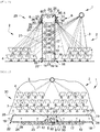
- Solar plant 1 of the figure 3 illustrates a specific configuration of a valley in a mountainous or hilly area located in a tropical or intertropical zone.
- the valley is here oriented East-West.
- the solar plant 1 is also in the form of a tunnel 30 resting on the ground.
- the reflection system 2 comprises two sets of reflectors 4 respectively arranged in a staircase on two slopes facing each other.
- the two sets of reflectors 4 are oriented so as to reflect respectively the incident solar rays 3 in the direction of two distinct points of convergence 5. More precisely, in this example, the two points of convergence 5 are arranged at the level of two opposite side walls 90, and located in the lower part of the transformation chamber 8.
- the present invention also relates to a process for transforming raw material, using a solar plant 1.
- the process comprises a step of reflecting the incident solar rays 3 in the direction of at least one point of convergence 5. This orientation contribute to optimize the accumulation of solar thermal energy, the source of which is free, non-polluting and inexhaustible.
- the transformation process has a step of raising the temperature of the transformation chamber 8.
- the rise in temperature of the transformation chamber 8 results from its cooperation with the concentration and diffusion means 6 of the solar plant 1.
- the method also includes a step of conveying the raw material.
- the raw material is conveyed from the outside of the solar furnace 1 to the processing chamber 8. Here, the raw material is transported via a conveyor 10.
- the method comprises a step of progressive preheating of the raw material during the conveyance to the processing chamber 8. This step is carried out using the heat exchanger (s) 23 which extends (ent ) between the inlet duct 17 and the outlet duct 18.
- the gradual preheating is carried out by a transfer of heat from the material transformed to the material to be transformed as described above.
- the method includes a step of transforming the raw material. This step takes place in the transformation chamber 8 at a defined temperature.
- the raw material is transformed by cooking, melting, thermal or photo thermal reaction, or thermo-catalysis, etc ...
- the transformation of the raw material can reside in a change of physical state or in thermo-catalysis a chemical reaction such as a polymerization and / or crosslinking reaction.
- the transformation process can comprise a step of adjusting the temperature of the transformation chamber 8. This adjustment step is carried out by varying the number of heliostats, or using the gas burner. The latter makes it possible to compensate for a loss of input in incident solar rays due for example to a cloudy passage.
- the transformation process can include a step of creating a reducing atmosphere. This step can be carried out by adding biogas within the enclosure of the transformation chamber 8.
- the addition of biogas reduces the supply of air into the enclosure of the transformation chamber 8 and makes it possible to reduce the material first.
- the addition of biogas can be carried out by a burner.
- the transformation process includes a step of removing the transformed material.
- the transformed material is then discharged from the transformation chamber 8 to the outside of the solar plant 1. As described above, the discharge of the raw material is carried out by the conveyor 10.
- solar plant 1 can be integrated into an industrial production line. On leaving solar plant 1, the transformed material can undergo further modifications made by other production and / or processing tools.
- the solar plant 1 advantageously makes it possible to catalyze or to carry out a step of transformation of a raw material or of a pre-transformed material or of a precursor material.
Landscapes
- Engineering & Computer Science (AREA)
- Chemical & Material Sciences (AREA)
- Life Sciences & Earth Sciences (AREA)
- Sustainable Development (AREA)
- Sustainable Energy (AREA)
- Thermal Sciences (AREA)
- Physics & Mathematics (AREA)
- Combustion & Propulsion (AREA)
- Mechanical Engineering (AREA)
- General Engineering & Computer Science (AREA)
- Engine Equipment That Uses Special Cycles (AREA)
- Waste-Gas Treatment And Other Accessory Devices For Furnaces (AREA)
- Container, Conveyance, Adherence, Positioning, Of Wafer (AREA)
Description
- La présente invention entre dans le domaine des énergies renouvelables et plus particulièrement de l'énergie solaire. L'invention se rapporte plus précisément, au domaine de l'énergie solaire concentrée, notamment sous la forme d'usine solaire à simple réflexion. Cette usine solaire peut être appliquée à une industrie requérant de grandes puissances thermiques comprises entre 1 à 100 Mégawatt. Une telle puissance thermique correspond à des températures de transformation industrielle comprise entre 200 et 3500 °C.
- L'énergie solaire est gratuite, non polluante et inépuisable. Ces avantages ont conduit au développement de technologies de transformation de l'énergie solaire en énergie électrique et/ou calorifique. De manière générale, le four solaire à double réflexion a été développé à partir de 1949, pour transformer l'énergie solaire concentrée par un système de réflexion optique. Le système de réflexion optique est composé de miroirs concentrant les rayons solaires en énergie thermique à très haute température entre 2000 et 4000 °C ou en électricité. Ce type d'installations était initialement développé pour des applications spéciales et/ou scientifiques.
- L'objectif du four solaire est de fournir une alternative à la production d'énergie issue de la combustion de combustibles naturels fossiles. Ces énergies dites fossiles sont de plus en plus chères et polluantes. Le développement des fours solaires peut également contribuer à préserver la ressource en combustible ligneux, permettant une lutte efficace et réelle contre la déforestation.
- Actuellement, il est possible de trouver plusieurs types de four solaire, les fours à réflexion simple, ou fours solaires à double réflexion, mais aussi des fours solaires héliothermiques et les centrales solaires photovoltaïques.
- De manière générale, un four solaire à double réflexion est composé d'un concentrateur de forme parabolique ou sphérique qui est revêtu de miroirs déformés pour concentrer très fortement, de 2000 à 16000 fois, les rayons solaires. Les rayons solaires sont concentrés vers un point de convergence dénommé foyer optique où l'on obtient des températures très élevées entre 2000 et 4000 °C. Le concentrateur est fixe et insolé toute la journée, par un ou plusieurs héliostats, qui sont des miroirs plans orientables. Les héliostats suivent automatiquement la course du soleil toute la journée.
- En parallèle, un four solaire à simple réflexion comporte un ensemble d'héliostats focalisant, qui suivent le soleil toute la journée et réfléchissent, en les concentrant, les rayons solaires vers une chaudière contenant un fluide caloporteur. Le fluide caloporteur peut être stocké ou utilisé en vue de produire de la vapeur dont la pression est utilisée pour actionner une turbine entrainant un alternateur.
- Le four solaire à simple réflexion concentre moins les rayons solaires que le four à double réflexion, la température du foyer focal y est par conséquent moins élevée, de l'ordre de 1000 à 2000 °C. Toutefois, les puissances directement liées à la surface de réflexion sont beaucoup plus importantes et peuvent atteindre plusieurs dizaines de Mégawatts.
- Le document
WO 2014/052902 décrit un premier exemple de four solaire à double réflexion. Le four solaire comprend un ou plusieurs réflecteurs optiques qui sont dans ce document de type héliostat. Les réflecteurs optiques sont organisés et orientés de manière à refléter les rayons solaires incidents vers un concentrateur optique. Le concentrateur optique réoriente les rayons solaires en les reflétant vers un point de convergence. - Le document
WO 2014/052902 propose de positionner au niveau du point de convergence des moyens d'absorption d'énergie. Les moyens d'absorption d'énergie peuvent être, d'une part, de type calorifique en utilisant par exemple un système d'échangeur thermique, et/ou, d'autre part, de type électromagnétique en utilisant un élément photovoltaïque. Dans les deux cas, l'objectif est de transformer l'énergie solaire en énergie thermique et/ou électrique. - Un autre exemple tel que le document
WO 2015/174236 décrit un four solaire à production d'énergie calorifique à double réflexion. Ce type de four solaire permet de concentrer les rayons solaires en vue de générer de l'énergie calorifique par transfert calorifique. En pratique, les rayons solaires incidents sont reflétés par des réflecteurs optiques en direction d'un concentrateur qui dirige l'ensemble des rayons solaires reflétés en un point de convergence. - Le document
WO 2015/174236 positionne au niveau du point de convergence un absorbeur calorifique qui permet d'absorber l'énergie calorifique des rayons solaires reflétés et concentrés. L'énergie calorifique absorbée est transformée en énergie électrique au travers d'un processus complexe impliquant la combustion de gaz combustibles issus de la thermolyse de charbon en vue de produire de la vapeur d'eau actionnant un alternateur électrique via la rotation d'une turbine. - Ces documents utilisent un four solaire pour la production d'énergie électrique ou l'accumulation d'énergie calorifique. A la différence de l'énergie électrique, l'énergie calorifique est plus facilement stockable, par exemple, au travers d'un liquide calorifique qui peut être conservé dans un réservoir isolé thermiquement.
- Cependant, l'utilisation directe de l'énergie solaire produite par un four solaire permet d'améliorer le rendement du four solaire. L'énergie solaire peut alors être directement utilisée dans le cadre d'un process industriel.
- Selon ce postulat, le document
US 4,706,651 décrit une usine solaire qui comprend une chambre de transformation d'une roche calcaire en chaux. L'usine solaire comporte un système de réflexion à simple réflexion. Ce système de réflexion concentre le rayonnement solaire en direction d'une ouverture ménagée dans la chambre de transformation. Le point de convergence est situé au niveau d'un absorbeur calorifique qui est solidaire du plafond de la chambre. Selon ce document, l'absorbeur calorifique est constitué par un tapis roulant confectionné avec de petites pièces d'un matériau réfractaire. Le tapis roulant tourne afin que l'absorbeur calorifique se refroidisse en continu. En parallèle, au bas de la chambre de transformation une vis sans fin fait office de convoyeur et transporte la roche calcaire qui se transforme progressivement en chaux. Il à noter que la transformation de la roche calcaire en chaux ou oxyde de calcium se produit par calcination à une température d'environ 900°C selon la réaction suivante : CaCO3 minéral ou roche → CaO solide + CO 2 gaz - Ainsi, le tapis roulant de l'absorbeur calorifique permet de conserver une température d'environ 900°C.
- Le document
US 2015/0307960 décrit une autre usine solaire conçue pour le raffinage du magnésium. Le raffinage du magnésium est une réaction de vaporisation du magnésium qui se déroule à une température supérieure à 1107°C. Cette température seuil correspond au point d'ébullition du magnésium. Ici, l'usine solaire comporte un système de concentration des rayons solaires à simple réflexion qui comporte un miroir orientable en fonction de la course du soleil. Cette usine solaire comporte une chambre de transformation équipée d'une ouverture au niveau de laquelle se situe le point de convergence optique. Les briquettes de magnésium sont directement irradiées par les rayons solaires au travers d'une ouverture. En outre, ce document décrit dans un mode de réalisation alternatif, un convoyeur qui amène les briquettes de magnésium dans la chambre de transformation. - Les deux usines solaires connues de l'état de la technique permettent d'extraire un élément d'intérêt, ici de l'oxyde de calcium ou du magnésium, à partir d'une matière première. Or, les usines solaires décrites par ces documents ne permettent pas de réaliser, en continu, la cuisson de matériaux comme la brique, la céramique ou la terre cuite qui nécessitent une montée en température progressive.
- Afin de répondre à ce problème technique, la demanderesse a développé une solution technique qui permet d'utiliser directement l'énergie solaire en vue de catalyser ou de réaliser des processus industriels qui impliquent une montée progressive de la température.
- A cet effet, la présente invention concerne une usine solaire comprenant :
- un système de réflexion configuré pour réfléchir et orienter des rayons solaires incidents en direction d'au moins un point de convergence,
- des moyens de concentration et de diffusion des rayons solaires réfléchis par le système de réflexion,
- une chambre de transformation, coopérant avec les moyens de concentration et de diffusion, qui diffusent l'énergie calorifique des rayons solaires réfléchis à la chambre de transformation,
- un conduit d'entrée qui s'étend depuis une entrée de l'usine solaire jusqu'à la chambre de transformation,
- un conduit de sortie qui s'étend depuis la chambre de transformation jusqu'à une sortie de l'usine solaire,
- un convoyeur s'étendant depuis l'entrée jusqu'à la sortie en traversant la chambre de transformation, le convoyeur transporte de la matière première depuis l'entrée jusqu'à la sortie, ainsi la matière première passe transitoirement dans la chambre de transformation afin d'obtenir de la matière transformée.
- L'usine solaire se caractérise en ce qu'elle comprend au moins un échangeur thermique qui s'étend entre le conduit d'entrée et le conduit de sortie, de manière à transférer, l'énergie calorifique dégagée par la matière transformée au cours de son transit entre la chambre de transformation et la sortie de l'usine solaire, au conduit d'entrée dans lequel transite la matière première avant transformation.
- L'échangeur thermique contribue à générer une montée en température progressive au sein du conduit d'entrée à mesure que la matière première s'approche de la chambre de transformation. De plus, l'échangeur thermique fournit une descente progressive en température au fur et à mesure que la matière transformée s'éloigne de la chambre de transformation. Une telle usine solaire permet de réaliser des processus industriels qui requièrent une montée et/ou une descente progressive en température. En ce sens, l'usine solaire selon l'invention permet d'industrialiser, à partir d'énergies renouvelables, des procédés industriels tels que la cuisson de la céramique, la faïence, la brique, la terre cuite etc.
- En outre, l'échangeur thermique optimise le rendement énergétique de l'usine solaire en transférant l'énergie calorifique qui se dégage de la matière transformée vers le conduit d'entrée.
- De surcroit, l'utilisation directe de l'énergie solaire permet d'améliorer le rendement du four solaire, passant de 20 à 30 % pour la production d'électricité, à 50 % pour le four solaire, et à 70 ou 75 % pour une usine solaire selon l'invention. Il en résulte qu'à puissance égale, une usine solaire présente un système de réflexion moins conséquent qu'un four solaire. Ceci permet de réduire également les coûts d'installation et d'entretien d'une usine solaire par rapport à un four solaire.
- Selon une première caractéristique de l'invention, les moyens de concentration et de diffusion comprennent au moins un absorbeur calorifique qui est disposé au niveau du point de convergence, d'une part, l'absorbeur calorifique absorbant l'énergie calorifique des rayons solaires réfléchis, et d'autre part, le au moins un absorbeur calorifique diffuse l'énergie calorifique des rayons solaires réfléchis à la chambre de transformation qui est disposée au contact de le au moins un absorbeur calorifique.
- Selon une deuxième caractéristique alternative de la première caractéristique de l'invention, les moyens de concentration et de diffusion comportent au moins une ouverture aménagée dans une paroi de la chambre de transformation, le système de réflexion orientant les rayons solaires réfléchis vers cette ouverture de manière à créer un point de convergence situé au niveau de l'ouverture de la chambre de transformation. Cet agencement permet d'obtenir un cône divergeant qui piège et déconcentre les rayons solaires à l'intérieur de la chambre de transformation. Ceci permet de chauffer l'enceinte de la chambre de transformation tout en évitant de fondre les isolants réfractaires qui tapissent les parois de la chambre de transformation.
- Selon une troisième caractéristique, la chambre de transformation comprend au moins un bruleur de gaz. Le bruleur de gaz permet d'ajuster la température régnant dans la chambre de transformation. Cependant, le bruleur permet également de générer une atmosphère réductrice en réduisant l'apport d'air comburant par ajout de carbone. De préférence, le bruleur fonctionne au biogaz. L'usine solaire peut ainsi fonctionner en biénergie 100% renouvelable.
- Selon une quatrième caractéristique, l'usine solaire comprend une source de matière première alimentant le convoyeur, la source de matière première est disposée en amont d'une entrée de la chambre de transformation.
- Selon une cinquième caractéristique, le système de réflexion comprend au moins un ou plusieurs réflecteur(s) optique(s) et/ou le système de réflexion comprend un ou plusieurs concentrateurs optiques. En particulier, un concentrateur optique peut être composé de plusieurs miroirs focalisant fixés sur une charpente orientable ou fixe.
- Selon une sixième caractéristique, l'usine solaire est isolée thermiquement par un revêtement isolant. Le revêtement isolant contribue à optimiser le rendement énergétique de l'usine solaire.
- Selon une septième caractéristique, l'usine solaire comporte une succession d'échangeurs thermiques disposés à intervalles réguliers entre la chambre de transformation et la sortie de l'usine solaire. Plus précisément, chaque échangeur thermique s'étendant entre un premier point disposé dans le conduit de sortie et un second point disposé dans le conduit d'entrée.
- La présente invention concerne également un procédé de transformation de matière première qui se caractérise en ce qu'il comporte :
- Une étape de réflexion des rayons solaires incidents en direction d'au moins un point de convergence ;
- Une étape de montée en température, d'une chambre de transformation coopérant avec des moyens de concentration et diffusion des rayons solaires réfléchis ;
- Une étape d'acheminement d'une matière première depuis l'extérieur de l'usine solaire vers la chambre de transformation, la matière première étant transportée par l'intermédiaire d'un convoyeur ;
- Une étape de préchauffage progressif de la matière première lors de l'acheminement vers la chambre de transformation ;
- Une étape de transformation de la matière première au sein de la chambre de transformation produisant de la matière transformée ; et
- Une étape d'évacuation de la matière transformée de la chambre de transformation vers l'extérieur de l'usine solaire via le convoyeur.
- D'autres particularités et avantages apparaitront dans la description détaillée qui suit, de deux exemples de réalisation, non limitatifs, de l'invention qui sont illustrés par les
figures 1 à 3 placées en annexe et dans lesquelles : - [
Fig.1 ] Lafigure 1 est une représentation d'une usine solaire 1 installée en plaine ; - [
Fig.2 ] Lafigure 2 est une représentation d'une usine solaire orientée Est-Ouest et installée dans une zone géographique vallonnée ou montagneuse avec une pente plein Sud, recevant les héliostats focalisant ; et - [
Fig.3 ] Lafigure 3 est une représentation latérale d'une usine solaire orientée Est-Ouest et installée dans une vallée d'une zone tropicale ou intertropicale, les héliostats étant installés sur les pentes Nord et Sud de la vallée. - Comme illustrée aux
figures 1 à 3 , la présente invention concerne une usine solaire 1 qui utilise directement l'énergie solaire en vue de catalyser/ou de réaliser un processus industriel. - Dans cet exemple, l'usine solaire 1 comprend un système de réflexion 2 configuré pour réfléchir, orienter et concentrer les rayons solaires incidents 3.
- A cet effet, le système de réflexion 2 comprend au moins un ou plusieurs réflecteur(s) 4 optique(s). Avantageusement, le ou les réflecteur(s) 4 optique(s) peuvent être orientable(s). Cette caractéristique permet de suivre la course du soleil tout au long d'une journée. Le rendement du four solaire 1 peut être ainsi optimisé.
- Dans l'exemple des
figures 1 à 3 , le ou les réflecteur(s) 4 optique(s) sont formés par des héliostats focalisant. Par ailleurs, le système de réflexion 2 peut également intégrer un ou plusieurs concentrateur(s) optique(s). Pour obtenir des températures plus élevées supérieures à 3000 °C. Une telle configuration reprend le concept du four solaire avec des héliostats plans. - Le système de réflexion 2 est configuré pour réfléchir et orienter les rayons solaires incidents 3 en direction d'au moins un point de convergence 5. Dans l'exemple des
figures 1 à 3 , le système de réflexion 2 est constitué de deux ensembles de réflecteurs 4. Chaque ensemble de réflecteurs 4 réfléchit respectivement les rayons solaires incidents 3 en direction d'un point de convergence 5 identique ou de deux points de convergence 5 distincts. - Il est connu de l'homme du métier que le point de convergence 5 d'un système de réflexion 2 constitue un foyer focal de dimensions définies. Le foyer focal peut comprendre des températures comprises entre 1000°C et 3500°C.
- Ici, le ou les réflecteur(s) 4 optique(s) sont orientés de manière à réfléchir les rayons solaires incidents 3 en direction du point de convergence 5.
- L'usine solaire 1 comprend des moyens de concentration et de diffusion 6 des rayons solaires réfléchis 7 par le système de réflexion 2. La chambre de transformation 8 coopère avec les moyens de concentration et de diffusion 6 qui diffusent l'énergie calorifique des rayons solaires réfléchis 7 à la chambre de transformation 8.
- Selon une première alternative, les moyens de concentration et de diffusion 6 comprennent au moins un absorbeur calorifique 60 disposé de manière à recevoir les rayons solaires réfléchis 7 par le système de réflexion 2. Dans cette optique, le au moins un absorbeur calorifique 60 est disposé au niveau du point de convergence 5. Ainsi, le au moins un absorbeur calorifique 60, absorbe l'énergie calorifique des rayons solaires réfléchis 7 par le système de réflexion 2. L'absorbeur calorifique 60 peut être réalisé dans un matériau réfractaire tel que le carbure de silicium. Le matériau réfractaire présente également des propriétés de conducteur de la chaleur. L'absorbeur calorifique 60 permet d'absorber l'énergie calorifique des rayons solaires réfléchis 7.
- Comme illustrée aux
figures 1 à 3 , l'usine solaire 1 comprend une chambre de transformation 8. La chambre de transformation 8 est délimitée par des parois 9. Dans cet exemple, les parois 9 délimitent une chambre de transformation 8 de forme quadrangulaire. - Ainsi, la chambre de transformation 8 comporte quatre parois latérales 90 parallèles deux à deux. En outre, la chambre de transformation 8 comprend également une paroi supérieure 91 perpendiculaire aux parois latérales 90. La paroi supérieure 91 est également parallèle d'une paroi inférieure 92.
- Toutefois, la chambre de transformation 8 peut prendre diverses formes tridimensionnelles telles qu'une forme cylindrique, pyramidale etc.
- La disposition de la chambre de transformation 8 est déterminée en fonction de l'organisation du système de réflexion 2. Comme illustrée aux
figures 1 à 3 , la chambre de transformation 8 peut reposer sur le sol ou être disposée à une hauteur déterminée du sol. En particulier, la disposition de la chambre de transformation 8 est liée à la position du ou des point(s) de convergence(s) 5. - La chambre de transformation 8 contribue à utiliser directement l'énergie solaire en vue de catalyser ou de réaliser un processus industriel. A cet effet, la chambre de transformation 8 est placée au contact d'au moins un absorbeur calorifique 60. Dans le présent exemple, au moins une paroi 9, 90, 91, 92 de la chambre de transformation 8 est recouverte au moins partiellement par un absorbeur calorifique 60. Selon cette configuration, l'absorbeur calorifique 60 se présente sous la forme d'un panneau recouvrant au moins partiellement une paroi 9, 90, 91, 92 de la chambre de transformation 8.
- De préférence et comme illustrées aux
figures 1 à 3 , au moins deux parois latérales 90 sont au moins partiellement recouvertes par un absorbeur calorifique 60. De préférence, les parois latérales 90 intègrent au moins partiellement un absorbeur calorifique 60. - En pratique, la disposition d'un ou de plusieurs absorbeur(s) calorifique(s) 6 dépend du nombre de parois 9, 90, 91, 92 de la chambre calorifique 8 exposées aux rayons solaires réfléchis 7.
- De manière générale, la chambre de transformation 8 est délimitée par des parois 9, 90, 91, 92 qui sont réalisées au moins en partie dans un matériau conducteur de chaleur. Ainsi, l'énergie calorifique captée par le au moins un absorbeur calorifique 60 est transférée à la chambre de transformation 8. Ce transfert d'énergie calorifique entraine une montée en température de la chambre de transformation 8. La chambre de transformation 8 est assimilable à « un four à énergie solaire ».
- Selon une seconde alternative, les moyens de concentration et de diffusion 6 comportent au moins une ouverture. La, au moins une ouverture est ménagée dans une paroi 9, 90, 91, 92 de la chambre de transformation 8. De préférence, les moyens de concentration et de diffusion 6 comportent au moins deux ouvertures ménagées respectivement dans deux parois 9, 90, 91, 92 opposées l'une de l'autre. En particulier, la au moins une ouverture est disposée en partie basse d'une paroi 9, 90, 91, 92 de la chambre de transformation 8.
- Selon cette alternative, le système de réflexion 2 oriente les rayons solaires réfléchis 7 en direction de la, au moins une ouverture. Les rayons solaires réfléchis 7 pénètrent ainsi dans l'enceinte de la chambre de transformation 8 et créent un point de convergence 5 au niveau de l'ouverture. Les dimensions de l'ouverture correspondent aux dimensions du foyer focal. Dans cette configuration, le point de convergence 5 crée un cône de divergence optique qui déconcentre et diffuse la lumière au sein de la chambre de transformation 8.
- L'usine solaire 1 peut être équipée sans modifications structurelles de l'une des deux alternatives de mise en œuvre des moyens de concentration et de diffusion 6.
- Avantageusement, la chambre de transformation 8 comprend au moins un bruleur de gaz. De préférence, la chambre de transformation 8 comprend au moins un bruleur de biogaz. Le, au moins un brûleur de gaz contribue à ajuster la température régnant dans la chambre de transformation 8. Bien entendu, le bruleur de gaz est alimenté via un système d'alimentation en gaz. Le, au moins un bruleur de gaz peut être manuel, semi-automatique ou automatique. Lorsque le bruleur est automatique, il peut être contrôlé par les moyens de gestion. L'usine solaire 1 fonctionne alors en biénergie totalement renouvelables.
- La chambre de transformation 8 peut également comprendre un capteur de température relié aux moyens de gestion. Ainsi, lorsqu'un passage nuageux diminue l'apport en rayon solaire, le, au moins un bruleur peut être utilisé pour ajuster la température de la chambre de transformation 8.
- Afin de produire de nuit, il n'est pas exclu que le, au moins un bruleur puisse maintenir la chambre de transformation 8 à une température déterminée.
- L'usine solaire 1 possède en outre un convoyeur 10. Le convoyeur 10 est schématisé par des flèches au travers des conduits 14, 17, 21 (
figure 1 et 2 ). Le convoyeur 10 assure le transport de matière première depuis l'extérieur du l'usine solaire 1 jusqu'à la chambre de transformation 8. - Dans cet exemple, le convoyeur 10 est disposé traversant de la chambre de transformation 8. En premier lieu, le convoyeur 10 pénètre dans la chambre de transformation 8 au travers d'une entrée 11. L'entrée 11 de la chambre de transformation 8 peut comprendre des moyens de fermeture 12. A titre d'exemple, les moyens de fermeture 12 peuvent être formés par une porte, un sas etc.
- En second lieu, le convoyeur 10 sort de la chambre de transformation 8 via une sortie 13. De la même manière, la sortie 13 de la chambre de transformation 8 peut comprendre des moyens de fermeture 12. Les moyens de fermeture 12 peuvent être formés par une porte, un sas etc. De manière générale, les moyens de fermeture 12 peuvent être actionnés manuellement ou contrôlés par les moyens de gestion.
- L'entrée 11 et la sortie 13 de la chambre de transformation 8 peuvent être disposées sur une même paroi 9, 90, 91, 92 de la chambre de transformation 8. Cependant, il est aussi possible de disposer respectivement l'entrée 11 et la sortie 13 de la chambre de transformation 8 sur deux parois 9, 90, 91, 92 distinctes.
- Ainsi, le convoyeur 10 fait passer transitoirement la matière première au sein de la chambre de transformation 8. De préférence, le temps de passage de la matière première dans la chambre de transformation 8 est défini. Le temps de passage de la matière première est défini selon la nature de la matière première et la nature de la transformation que l'on souhaite obtenir. Avantageusement, le fait de contrôler le temps de passage de la matière première dans la chambre de transformation 8 permet d'industrialiser un processus de transformation de matière première.
- La transformation de matière peut correspondre à un changement d'état physique telles que la fusion d'un solide, ou à l'inverse la solidification d'un matériau ductile ou cru telle que la cuisson de la céramique, la terre cuite, la brique, la faïence. A titre d'exemple, la cuisson de la faïence peut être inférieure à 2 heures à 1000 °C. Ces matériaux ductiles crus ont la particularité de nécessiter une montée en température progressive pour éviter un craquèlement ou une rupture de la matière ou de l'objet que l'on souhaite cuire.
- Il est à noter que le convoyeur 10 peut être formé par tout système mécanique, automatique ou semi-automatique qui permet d'assurer le transport de matière première. A titre indicatif, le convoyeur 10 peut être formé par des wagonnets montés sur rails. Les wagonnets et les rails peuvent être réfractaires. Dans ce cas, les rails sont montés traversant de la chambre de transformation 8.
- Par ailleurs, afin de contrôler le temps de passage de la matière première dans la chambre de transformation 8, l'usine solaire 1 peut comprendre des moyens de gestion automatique de l'actionnement du convoyeur 10.
- Les moyens de gestion peuvent être formés par un ordinateur possédant un microprocesseur et une mémoire. Le microprocesseur est alors configuré pour exécuter un programme de cuisson stocké dans la mémoire. Le programme de cuisson peut être paramétrable par un utilisateur au travers d'une interface classique.
- La durée d'exposition à la chaleur de la matière première dans la chambre de transformation 8 dépend de la température qui règne dans la chambre de transformation 8 et de la vitesse du convoyeur 10. La température de la chambre de transformation 8 dépend, quant à elle, de plusieurs facteurs tels que le taux de concentration des rayons solaires réfléchis, le coefficient d'absorption de la matière première etc.
- Le convoyeur 10 peut être alimenté en énergie par une source d'énergie électrique. L'énergie électrique peut provenir d'une source d'énergie électrique renouvelable telle que des photopiles ou un réseau de distribution électrique.
- Comme illustrée aux
figures 1 à 3 , l'usine solaire 1 comprend au moins un conduit 14. Le, au moins un conduit 14 s'étend entre deux extrémités 15, 16. Dans cet exemple, le, au moins un conduit 14 s'étend d'une première extrémité 15 raccordée à la chambre de transformation 8 en direction d'une seconde extrémité libre 16. De préférence, l'usine solaire 1 possède deux conduits 14. - Un premier conduit 14 est raccordé à l'entrée 11 de la chambre de transformation 8. Ce premier conduit 14 est défini comme un conduit d'entrée 17 de l'usine solaire 1. L'extrémité libre 16 du conduit d'entrée 17 correspond à l'entrée 18 de l'usine solaire 1. L'entrée 18 de l'usine solaire 1 comprend un organe de fermeture 19. A titre indicatif, l'organe de fermeture 19 peut être formé par une porte d'ouverture, un sas etc. L'organe de fermeture 19 peut être automatique, semi-automatique ou manuel. Lorsque l'organe de fermeture 19 est automatique il peut être contrôlé par les moyens de gestion.
- Par ailleurs, un second conduit 14 est raccordé à la sortie 13 de la chambre de transformation 8. Le second conduit 14 est défini comme un conduit de sortie 21 de l'usine solaire 1. L'extrémité libre 16 du conduit de sortie 21 correspond à la sortie 22 de l'usine solaire 1.
- Il est à noter que le conduit d'entrée 18 et le conduit de sortie 21 peuvent être agencés de différentes façons. Les conduits peuvent s'étendre dans un même plan et/ou selon une même direction. Le plan dans lequel s'étendent les deux conduits 14, 17, 21 peut prendre plusieurs orientations. Par exemple, aux
figures 2 et3 , les deux conduits 14, 17, 21 sont disposés en ligne selon un plan parallèle au sol. Cependant, les deux conduits 14, 17, 21 peuvent être également disposés dans un même plan et/ou selon un agencement en aller et retour. Dans lafigure 1 , les deux conduits 14, 17, 21 sont disposés en aller et retour selon un plan perpendiculaire au sol. - Le convoyeur 10 s'étend au travers d'au moins un conduit 14, 17, 21 depuis l'extérieur du four solaire 1 jusqu'à la chambre de transformation 8.
- Dans cet exemple, le convoyeur 10 s'étend depuis l'entrée 18 de l'usine solaire 1 jusqu'à la sortie 22 du four solaire 1 en traversant la chambre de transformation 8. Ainsi, le convoyeur 10 traverse successivement le conduit d'entrée 17, la chambre de transformation 8 et le conduit de sortie 21.
- L'usine solaire 1 comprend une source de matière première alimentant le convoyeur 10. La source de matière première est disposée en amont de l'entrée 11 de la chambre de transformation 8. De préférence, la source de matière première est disposée en amont de l'entrée 18 de l'usine solaire 1.
- La source de matière première peut être automatique, semi-automatique ou manuelle. Dans ce dernier cas, un opérateur chargera au fur et à mesure le convoyeur 10 de matière première.
- Par ailleurs, en aval de la chambre de transformation 8 et de préférence en aval du conduit de sortie 21, l'usine solaire 1 comprend une zone de déchargement de la matière transformée. Le déchargement du convoyeur 10 peut être réalisé soit manuellement soit à l'aide d'un système automatique ou semi-automatique.
- Avantageusement, l'usine solaire 1 est équipée d'au moins un échangeur thermique 23. Comme illustré aux
figures 1 à 3 , le au moins un échangeur thermique 23 s'étend entre le conduit d'entrée 17 et le conduit de sortie 21. En pratique, le au moins un échangeur thermique 23 permet de transférer, un surplus d'énergie calorifique emmagasiné par la matière transformée lors de son passage dans la chambre de transformation 8, vers le conduit d'entrée 17 dans lequel transite de la matière non transformée. En effet, en sortie de la chambre de transformation 8, ce surplus d'énergie calorifique est libéré sous forme de chaleur par la matière transformée et constitue une source d'énergie calorifique. - Dans cet exemple, l'usine solaire 1 comporte une succession d'échangeurs thermiques 23 disposés à intervalles réguliers entre la chambre de transformation 8 et la sortie 22 de l'usine solaire 1. Chaque échangeur thermique 23 s'étend entre un premier point disposé dans le conduit de sortie 21 et un second point disposé dans le conduit d'entrée 17.
- De préférence, le premier et le second point sont équidistants de la chambre de transformation 8. Cette configuration spécifique contribue à fournir, au niveau du conduit d'entrée 17, une montée en température progressive depuis l'entrée du four solaire 18 jusqu'à la chambre de transformation 8.
- Il est à noter que l'échangeur thermique 23 peut être de type air-air ou encore de type air-eau ou autre. Dans le cas d'un échangeur thermique 23 de type air-air, celui-ci peut être couplé avec un système de ventilation/aspiration. L'échangeur thermique 23 peut être activé ou désactivé en fonction notamment de la nature de la matière première et/ou du type de transformation que l'on souhaite obtenir.
- A cet effet, les moyens de gestion peuvent être utilisés au travers de leur interface pour commander le fonctionnement de l'échangeur thermique 23.
- L'usine 1 est isolée thermiquement au travers d'un revêtement d'isolation 24 qui recouvre au moins partiellement la chambre de transformation 8.
- Le revêtement d'isolation 24 recouvre également au moins partiellement le au moins un conduit 14, 17, 21. De préférence, le revêtement d'isolation 24 recouvre entièrement le conduit d'entrée 17 et le conduit de sortie 21.
- Dans cet exemple, il est préférable d'utiliser un matériau isolant réfractaire et encore préférentiellement, un matériau isolant réfractaire haute température. Ceci est particulièrement avantageux à l'intérieur et à proximité de la chambre de transformation 8.
- Le revêtement d'isolation 24 réduit les déperdissions d'énergie calorifique et permet d'optimiser le rendement calorifique de l'usine solaire 1.
- Il est à noter que les parois 9, 90, 91, 92 peuvent également être recouvertes intérieurement d'un revêtement isolant réfractaire. Ceci favorise la montée en température de la chambre de transformation 8. De surcroît, les parois 9, 90, 91, 92 recouvertes intérieurement d'un revêtement isolant réfractaire participe à limiter les déperdissions thermiques.
- Également dans l'objectif d'isoler l'usine solaire 1, la chambre de transformation 8 peut être équipée d'une toiture 25. La toiture 25 comporte une extension saillante 26. De préférence, l'extension saillante 26 s'étend, depuis la paroi supérieure 91, sur le pourtour de la chambre de transformation 8. Avantageusement, l'extension saillante 26 comporte sur sa face interne un revêtement isolant 24 tel que décrit précédemment. De préférence, le revêtement isolant 24 est de type réfractaire. Avantageusement, le revêtement isolant 24 réfractaire permet de réduire les pertes d'énergie calorifique non absorbée par l'absorbeur calorifique 6.
- La toiture 25 comprend, par ailleurs, un revêtement externe 28 de type bardage tel que décrit précédemment.
- Dans l'exemple illustré aux
figures 1 à 3 , le four solaire 1 comporte un bardage 28. Le bardage 28 recouvre et protège le revêtement d'isolation 24 des dégradations extérieures dues, par exemple, aux intempéries. De préférence, le bardage 28 est réalisé en métal tel que l'inox. A titre indicatif, il est possible d'utiliser des panneaux de tôle en inox pour réaliser le bardage 28 de l'usine solaire 1. - Il est bien connu de la littérature scientifique que l'orientation des rayons solaires incidents 3 varie en fonction de la situation géographique et de la topographie d'une région.
- La
figure 1 illustre une usine solaire 1 conforme à l'invention qui est configurée de manière à être utilisée en plaine. Ainsi selon la spécificité de la région et de la topographie, l'usine solaire 1 se présente sous la forme d'une tour 29 verticale entourée par au moins deux ensembles de réflecteurs 4. La chambre de transformation 8 est disposée au sommet de la tour 29. - Ici, les deux ensembles de réflecteurs 4 sont orientés afin de réfléchir respectivement les rayons solaires incidents 3 en direction de deux points de convergence 5 distincts. Chaque point de convergence 5 est disposé au niveau d'une paroi latérale 90 distincte de la chambre de transformation 8.
- Selon cet exemple de réalisation, l'usine solaire 1 comporte deux conduits 14, 17, 21. Le conduit d'entrée 17 et le conduit de sortie 21 de l'usine solaire 1 sont disposés dans le même plan et selon un agencement en aller-retour vertical.
- L'usine solaire 1 de la
figure 2 , présente une configuration spécifique d'une région montagneuse ou vallonée située au sud de l'Europe. Ici, l'usine solaire 1 se présente sous la forme d'un tunnel 30 en ligne, parallèle au sol et orienté Est-Ouest, reposant sur le sol. Le tunnel 30 comporte en son centre la chambre de transformation 8. Le conduit d'entrée 17 et le conduit de sortie 21 sont disposés en ligne de part et d'autre de la chambre de transformation 8. - Il est à noter que dans cet exemple, le système de réflexion 2 comprend un ou plusieurs ensembles de réflecteurs 4 qui sont disposés en espalier sur une pente orientée plein Sud dans l'hémisphère Nord. A l'inverse, si l'usine solaire 1 était installée dans l'hémisphère Sud, la pente, sur laquelle sont disposés les réflecteurs, serait orientée plein Nord. Les ensembles de réflecteurs 4 sont orientés automatiquement afin de réfléchir les rayons solaires incidents 3 en direction d'un même point de convergence 5.
- L'usine solaire 1 de la
figure 3 illustre quant à elle une configuration spécifique d'une vallée d'une zone montagneuse ou vallonée située en zone tropicale ou intertropicale. La vallée est ici orientée Est-Ouest. Selon cette configuration, l'usine solaire 1 se présente également sous la forme d'un tunnel 30 reposant au sol. Par ailleurs, le système de réflexion 2 comporte deux ensembles de réflecteurs 4 disposés respectivement en espalier sur deux pentes se faisant face. - Les deux ensembles de réflecteurs 4 sont orientés de manière à réfléchir respectivement les rayons solaires incidents 3 en direction de deux points de convergence 5 distincts. Plus précisément, dans cet exemple les deux points de convergence 5 sont disposés au niveau de deux parois latérales 90 opposées, et situées en partie basse de la chambre de transformation 8.
- Bien entendu, en fonction de la situation géographique et topographique du site d'installation de l'usine solaire 1, celle-ci peut être agencée différemment tout en conservant les caractéristiques que nous venons de décrire.
- D'autre part, la présente invention concerne également un procédé de transformation de matière première, utilisant une usine solaire 1. Le procédé comprend une étape de réflexion des rayons solaires incidents 3 en direction d'au moins un point de convergence 5. Cette orientation contribue à optimiser l'accumulation d'énergie solaire calorifique dont la source est gratuite, non polluante et inépuisable.
- Le procédé de transformation possède une étape de montée en température de la chambre de transformation 8. La montée en température de la chambre de transformation 8 résulte de sa coopération avec les moyens de concentration et de diffusion 6 de l'usine solaire 1.
- Le procédé comporte également une étape d'acheminement de la matière première. La matière première est acheminée depuis l'extérieur du four solaire 1 vers la chambre de transformation 8. Ici, la matière première est transportée par l'intermédiaire d'un convoyeur 10.
- Le procédé comporte une étape de préchauffage progressif de la matière première lors de l'acheminement vers la chambre de transformation 8. Cette étape est réalisée à l'aide du ou des échangeur(s) thermique(s) 23 qui s'étend(ent) entre le conduit d'entrée 17 et le conduit de sortie 18. Le préchauffage progressif est opéré par un transfert de chaleur depuis la matière transformée vers la matière à transformer comme décrit précédemment.
- Le procédé comprend une étape de transformation de la matière première. Cette étape se déroule au sein de la chambre de transformation 8 à une température définie. La matière première est transformée par cuisson, fusion, réaction thermique ou photo thermique, ou thermo-catalyse, etc... Comme évoqué précédemment, la transformation de la matière première peut résider en un changement d'état physique ou dans la thermo-catalyse d'une réaction chimique telle qu'une réaction de polymérisation et/ou de réticulation.
- Le procédé de transformation peut comprendre une étape d'ajustement de la température de la chambre de transformation 8. Cette étape d'ajustement est réalisée en faisant varier le nombre d'héliostats, ou à l'aide du bruleur de gaz. Ce dernier permet de compenser une perte d'apport en rayons solaires incidents due par exemple à un passage nuageux.
- Le procédé de transformation peut comprendre une étape de création d'une atmosphère réductrice. Cette étape peut être réalisée par ajout de biogaz au sein de l'enceinte de la chambre de transformation 8. L'ajout de biogaz réduit l'apport d'air dans l'enceinte de la chambre de transformation 8 et permet de faire de la réduction de la matière première. L'ajout de biogaz peut être réalisé par un bruleur.
- Le procédé de transformation comprend une étape d'évacuation de la matière transformée. La matière transformée est alors évacuée depuis la chambre de transformation 8 vers l'extérieur de l'usine solaire 1. Comme décrit précédemment, l'évacuation de la matière première est effectuée par le convoyeur 10.
- Il est à noter que l'usine solaire 1 peut être intégrée à une chaine de production industrielle. En sortie de l'usine solaire 1, la matière transformée peut subir de nouvelles modifications opérées par d'autres outils de production et/ou de transformation.
- Dans ce cas de figure, l'usine solaire 1 permet avantageusement de catalyser ou de réaliser une étape de transformation d'une matière première ou d'une matière pré-transformée ou encore d'une matière précurseur.
Claims (10)
- Usine solaire (1) comprenant :- un système de réflexion (2) configuré pour réfléchir et orienter des rayons solaires incidents (3) en direction d'au moins un point de convergence (5),- des moyens de concentration et de diffusion (6) des rayons solaires réfléchis (7) par le système de réflexion (2),- une chambre de transformation (8) coopérant avec les moyens de concentration et de diffusion (6) qui diffusent l'énergie calorifique des rayons solaires réfléchis (7) à la chambre de transformation (8),- un conduit d'entrée (17) qui s'étend depuis une entrée (18) de l'usine solaire (1) jusqu'à la chambre de transformation (8),- un conduit de sortie (21) qui s'étend depuis la chambre de transformation (8) jusqu'à une sortie (22) de l'usine solaire (1),- un convoyeur (10) s'étendant depuis l'entrée (18) jusqu'à la sortie (22) en traversant la chambre de transformation (8), le convoyeur (10) transporte de la matière première depuis l'entrée (18) jusqu'à la sortie (22), ainsi la matière première passe transitoirement dans la chambre de transformation (8) afin d'obtenir de la matière transformée,caractérisée en ce qu'elle comprend au moins un échangeur thermique (23) qui s'étend entre le conduit d'entrée (18) et le conduit de sortie (21), de manière à transférer, l'énergie calorifique dégagée par la matière transformée au cours de son transit entre la chambre de transformation (8) et la sortie (22) de l'usine solaire (1), au conduit d'entrée (18) dans lequel transite la matière première avant transformation.
- Usine solaire (1) selon la revendication 1, caractérisée en ce que les moyens de concentration et de diffusion (6) comprennent au moins un absorbeur calorifique (60) qui est disposé au niveau du point de convergence (5), d'une part, l'absorbeur calorifique (60) absorbant l'énergie calorifique des rayons solaires réfléchis (7), et d'autre part, le au moins un absorbeur calorifique (60) diffuse l'énergie calorifique des rayons solaires réfléchis (7) à la chambre de transformation (8) qui est disposée au contact de le au moins un absorbeur calorifique (60).
- Usine solaire (1) selon la revendication 1, caractérisée en ce que les moyens de concentration et de diffusion (6) comportent au moins une ouverture ménagée dans une paroi (9, 90, 91, 92) de la chambre de transformation (8), le système de réflexion (2) orientant les rayons solaires réfléchis (7) vers cette ouverture de manière à créer un point de convergence (5) situé au niveau de l'ouverture de la chambre de transformation (8).
- Usine solaire (1), selon l'une des revendications 1 à 3, caractérisée en ce que la chambre de transformation (8) comprend au moins un bruleur de gaz.
- Usine solaire (1) selon l'une des revendications 1 à 4, caractérisée en ce qu'elle comprend une source de matière première alimentant le convoyeur, la source de matière première est disposée en amont d'une entrée (11) de la chambre de transformation (8).
- Usine solaire (1) selon l'une des revendications 1 à 5, caractérisée en ce que, le système de réflexion (2) comprend au moins un ou plusieurs réflecteur(s) optique(s) (4) et/ou le système de réflexion (2) comprend un ou plusieurs concentrateurs optiques.
- Usine solaire (1) selon l'une des revendications 1 à 6, caractérisée en ce qu'elle est isolée thermiquement par un revêtement isolant (24).
- Usine solaire (1) selon l'une des revendications 1 à 7, caractérisée en ce qu'elle comporte une succession d'échangeurs thermiques (23) disposés à intervalles réguliers entre la chambre de transformation (8) et la sortie (22) de l'usine solaire (1).
- Usine solaire (1) selon la revendication 8, chaque échangeur thermique (23) s'étendant entre un premier point disposé dans le conduit de sortie (21) et un second point disposé dans le conduit d'entrée (17).
- Procédé de transformation de matière première utilisant une usine solaire (1) défini selon l'une des revendications 1 à 9, caractérisé en ce qu'il comporte :- une étape de réflexion des rayons solaires incidents en direction d'au moins un point de convergence (5) ;- une étape de montée en température d'une chambre de transformation (8) coopérant avec des moyens de concentration et diffusion (6) des rayons solaires réfléchis (7) ;- une étape d'acheminement d'une matière première depuis l'extérieur de l'usine solaire (1) vers la chambre de transformation (8), la matière première étant transportée par l'intermédiaire d'un convoyeur (10) ;- une étape de préchauffage progressif de la matière première lors de l'acheminement vers la chambre de transformation (8) ;- une étape de transformation de la matière première au sein de la chambre de transformation produisant de la matière transformée ; et- une étape d'évacuation de la matière transformée de la chambre de transformation (8) vers l'extérieur du four solaire (21) via le convoyeur (10).
Applications Claiming Priority (1)
| Application Number | Priority Date | Filing Date | Title |
|---|---|---|---|
| FR1903290A FR3094465B1 (fr) | 2019-03-28 | 2019-03-28 | Usine solaire et procede de transformation |
Publications (2)
| Publication Number | Publication Date |
|---|---|
| EP3715744A1 EP3715744A1 (fr) | 2020-09-30 |
| EP3715744B1 true EP3715744B1 (fr) | 2021-11-24 |
Family
ID=67441405
Family Applications (1)
| Application Number | Title | Priority Date | Filing Date |
|---|---|---|---|
| EP20166861.3A Active EP3715744B1 (fr) | 2019-03-28 | 2020-03-30 | Usine solaire et procédé de transformation |
Country Status (2)
| Country | Link |
|---|---|
| EP (1) | EP3715744B1 (fr) |
| FR (1) | FR3094465B1 (fr) |
Family Cites Families (6)
| Publication number | Priority date | Publication date | Assignee | Title |
|---|---|---|---|---|
| US4706651A (en) * | 1986-02-24 | 1987-11-17 | The United States Of America As Represented By The United States Department Of Energy | Solar solids reactor |
| US20140299121A1 (en) | 2012-09-30 | 2014-10-09 | William Stevens Taber, JR. | Radiation collection utilizing total internal reflection and other techniques for the purpose of dispatchable electricity generation and other uses |
| US20150308715A1 (en) * | 2012-12-28 | 2015-10-29 | Abengoa Solar Llc | Metal remelting with concentrated solar power |
| JP6032015B2 (ja) * | 2013-01-09 | 2016-11-24 | 株式会社ニコン | マグネシウム精錬装置およびマグネシウム精錬方法 |
| US9702348B2 (en) * | 2013-04-03 | 2017-07-11 | Alliance For Sustainable Energy, Llc | Chemical looping fluidized-bed concentrating solar power system and method |
| JP6440267B2 (ja) | 2014-05-13 | 2018-12-19 | 国立大学法人 新潟大学 | 集光太陽光の受熱装置、反応装置及び加熱装置 |
-
2019
- 2019-03-28 FR FR1903290A patent/FR3094465B1/fr not_active Expired - Fee Related
-
2020
- 2020-03-30 EP EP20166861.3A patent/EP3715744B1/fr active Active
Also Published As
| Publication number | Publication date |
|---|---|
| FR3094465B1 (fr) | 2021-10-01 |
| EP3715744A1 (fr) | 2020-09-30 |
| FR3094465A1 (fr) | 2020-10-02 |
Similar Documents
| Publication | Publication Date | Title |
|---|---|---|
| JP4420902B2 (ja) | 太陽エネルギー集積利用装置 | |
| Salvi et al. | Technological advances to maximize solar collector energy output: a review | |
| US20140190080A1 (en) | Chemical reactors with annularly positioned delivery and removal devices, and associated systems and methods | |
| US20110067687A1 (en) | Tracking Fiber Optic Wafer Concentrator | |
| US20110209979A1 (en) | Chemical reactors with annularly positioned delivery and removal devices, and associated systems and methods | |
| US20100300510A1 (en) | Solar energy systems with reflecting and photovoltaic conversion means | |
| CN102792022A (zh) | 会聚的太阳能电力系统 | |
| WO2003038348A1 (fr) | Systeme d'energie solaire adaptatif a spectre complet | |
| US5308187A (en) | Parking lot pavement for making hot precombustion air for a fossil fuel burner | |
| US20120298020A1 (en) | Gassification system | |
| Ma et al. | A review on solar concentrators with multi-surface and multi-element (MS/ME) combinations | |
| EP3715744B1 (fr) | Usine solaire et procédé de transformation | |
| MA35047B1 (fr) | Tube récepteur de chaleur, procédé de fabrication de tube récepteur de chaleur, collecteur solaire à miroir cylindro-parabolique doté du tube récepteur, et utilisation du collecteur solaire à miroir cylindro-parabolique | |
| FR2530297A1 (fr) | Dispositif producteur d'energie par rotation d'une helice sous l'effet d'un deplacement d'air | |
| KR102462124B1 (ko) | 유동층 공정을 이용한 태양열 화학적 에너지 생산 장치 | |
| CN215252114U (zh) | 一种辅助沥青加热的装置及沥青罐 | |
| CN201797463U (zh) | 负压膜结构旋转曲面聚光镜发电装置 | |
| KR101056941B1 (ko) | 접시형 태양열 집열장치 | |
| Bedreddine et al. | Exploitation of solar energy for the elaboration of zinc oxide thin films according to a new method of solar spray pyrolysis | |
| US20230221070A1 (en) | System and method for the thermal processing of bulk material by intense concentrated solar power | |
| Kumar et al. | Performance of cylindrical parabolic solar collector with the tracking system | |
| Chauhan et al. | Introduction and Fundamentals of Solar Energy Collectors | |
| WO2016062804A2 (fr) | Procédé et appareil pour le fonctionnement d'un four solaire 24 heures par jour | |
| CN119468512A (zh) | 一种塔式二次反射式光热烧制技术及控制方法 | |
| Lakshmipathy et al. | Influence of Cavity Materials and Selective Surface Coatings on the Performance of SCC |
Legal Events
| Date | Code | Title | Description |
|---|---|---|---|
| PUAI | Public reference made under article 153(3) epc to a published international application that has entered the european phase |
Free format text: ORIGINAL CODE: 0009012 |
|
| STAA | Information on the status of an ep patent application or granted ep patent |
Free format text: STATUS: THE APPLICATION HAS BEEN PUBLISHED |
|
| AK | Designated contracting states |
Kind code of ref document: A1 Designated state(s): AL AT BE BG CH CY CZ DE DK EE ES FI FR GB GR HR HU IE IS IT LI LT LU LV MC MK MT NL NO PL PT RO RS SE SI SK SM TR |
|
| AX | Request for extension of the european patent |
Extension state: BA ME |
|
| STAA | Information on the status of an ep patent application or granted ep patent |
Free format text: STATUS: REQUEST FOR EXAMINATION WAS MADE |
|
| 17P | Request for examination filed |
Effective date: 20210326 |
|
| RAV | Requested validation state of the european patent: fee paid |
Extension state: MA Effective date: 20210326 |
|
| RBV | Designated contracting states (corrected) |
Designated state(s): AL AT BE BG CH CY CZ DE DK EE ES FI FR GB GR HR HU IE IS IT LI LT LU LV MC MK MT NL NO PL PT RO RS SE SI SK SM TR |
|
| RIC1 | Information provided on ipc code assigned before grant |
Ipc: F24S 20/20 20180101AFI20210420BHEP Ipc: F24S 20/30 20180101ALI20210420BHEP Ipc: F26B 3/28 20060101ALI20210420BHEP |
|
| GRAP | Despatch of communication of intention to grant a patent |
Free format text: ORIGINAL CODE: EPIDOSNIGR1 |
|
| STAA | Information on the status of an ep patent application or granted ep patent |
Free format text: STATUS: GRANT OF PATENT IS INTENDED |
|
| INTG | Intention to grant announced |
Effective date: 20210707 |
|
| GRAA | (expected) grant |
Free format text: ORIGINAL CODE: 0009210 |
|
| STAA | Information on the status of an ep patent application or granted ep patent |
Free format text: STATUS: THE PATENT HAS BEEN GRANTED |
|
| GRAS | Grant fee paid |
Free format text: ORIGINAL CODE: EPIDOSNIGR3 |
|
| AK | Designated contracting states |
Kind code of ref document: B1 Designated state(s): AL AT BE BG CH CY CZ DE DK EE ES FI FR GB GR HR HU IE IS IT LI LT LU LV MC MK MT NL NO PL PT RO RS SE SI SK SM TR |
|
| REG | Reference to a national code |
Ref country code: GB Ref legal event code: FG4D Free format text: NOT ENGLISH |
|
| REG | Reference to a national code |
Ref country code: AT Ref legal event code: REF Ref document number: 1450151 Country of ref document: AT Kind code of ref document: T Effective date: 20211215 |
|
| REG | Reference to a national code |
Ref country code: IE Ref legal event code: FG4D Free format text: LANGUAGE OF EP DOCUMENT: FRENCH |
|
| REG | Reference to a national code |
Ref country code: DE Ref legal event code: R096 Ref document number: 602020001073 Country of ref document: DE |
|
| REG | Reference to a national code |
Ref country code: LT Ref legal event code: MG9D |
|
| REG | Reference to a national code |
Ref country code: NL Ref legal event code: MP Effective date: 20211124 |
|
| REG | Reference to a national code |
Ref country code: AT Ref legal event code: MK05 Ref document number: 1450151 Country of ref document: AT Kind code of ref document: T Effective date: 20211124 |
|
| PG25 | Lapsed in a contracting state [announced via postgrant information from national office to epo] |
Ref country code: RS Free format text: LAPSE BECAUSE OF FAILURE TO SUBMIT A TRANSLATION OF THE DESCRIPTION OR TO PAY THE FEE WITHIN THE PRESCRIBED TIME-LIMIT Effective date: 20211124 Ref country code: LT Free format text: LAPSE BECAUSE OF FAILURE TO SUBMIT A TRANSLATION OF THE DESCRIPTION OR TO PAY THE FEE WITHIN THE PRESCRIBED TIME-LIMIT Effective date: 20211124 Ref country code: FI Free format text: LAPSE BECAUSE OF FAILURE TO SUBMIT A TRANSLATION OF THE DESCRIPTION OR TO PAY THE FEE WITHIN THE PRESCRIBED TIME-LIMIT Effective date: 20211124 Ref country code: BG Free format text: LAPSE BECAUSE OF FAILURE TO SUBMIT A TRANSLATION OF THE DESCRIPTION OR TO PAY THE FEE WITHIN THE PRESCRIBED TIME-LIMIT Effective date: 20220224 Ref country code: AT Free format text: LAPSE BECAUSE OF FAILURE TO SUBMIT A TRANSLATION OF THE DESCRIPTION OR TO PAY THE FEE WITHIN THE PRESCRIBED TIME-LIMIT Effective date: 20211124 |
|
| PG25 | Lapsed in a contracting state [announced via postgrant information from national office to epo] |
Ref country code: IS Free format text: LAPSE BECAUSE OF FAILURE TO SUBMIT A TRANSLATION OF THE DESCRIPTION OR TO PAY THE FEE WITHIN THE PRESCRIBED TIME-LIMIT Effective date: 20220324 Ref country code: SE Free format text: LAPSE BECAUSE OF FAILURE TO SUBMIT A TRANSLATION OF THE DESCRIPTION OR TO PAY THE FEE WITHIN THE PRESCRIBED TIME-LIMIT Effective date: 20211124 Ref country code: PT Free format text: LAPSE BECAUSE OF FAILURE TO SUBMIT A TRANSLATION OF THE DESCRIPTION OR TO PAY THE FEE WITHIN THE PRESCRIBED TIME-LIMIT Effective date: 20220324 Ref country code: PL Free format text: LAPSE BECAUSE OF FAILURE TO SUBMIT A TRANSLATION OF THE DESCRIPTION OR TO PAY THE FEE WITHIN THE PRESCRIBED TIME-LIMIT Effective date: 20211124 Ref country code: NO Free format text: LAPSE BECAUSE OF FAILURE TO SUBMIT A TRANSLATION OF THE DESCRIPTION OR TO PAY THE FEE WITHIN THE PRESCRIBED TIME-LIMIT Effective date: 20220224 Ref country code: NL Free format text: LAPSE BECAUSE OF FAILURE TO SUBMIT A TRANSLATION OF THE DESCRIPTION OR TO PAY THE FEE WITHIN THE PRESCRIBED TIME-LIMIT Effective date: 20211124 Ref country code: LV Free format text: LAPSE BECAUSE OF FAILURE TO SUBMIT A TRANSLATION OF THE DESCRIPTION OR TO PAY THE FEE WITHIN THE PRESCRIBED TIME-LIMIT Effective date: 20211124 Ref country code: HR Free format text: LAPSE BECAUSE OF FAILURE TO SUBMIT A TRANSLATION OF THE DESCRIPTION OR TO PAY THE FEE WITHIN THE PRESCRIBED TIME-LIMIT Effective date: 20211124 Ref country code: GR Free format text: LAPSE BECAUSE OF FAILURE TO SUBMIT A TRANSLATION OF THE DESCRIPTION OR TO PAY THE FEE WITHIN THE PRESCRIBED TIME-LIMIT Effective date: 20220225 |
|
| PG25 | Lapsed in a contracting state [announced via postgrant information from national office to epo] |
Ref country code: SM Free format text: LAPSE BECAUSE OF FAILURE TO SUBMIT A TRANSLATION OF THE DESCRIPTION OR TO PAY THE FEE WITHIN THE PRESCRIBED TIME-LIMIT Effective date: 20211124 Ref country code: SK Free format text: LAPSE BECAUSE OF FAILURE TO SUBMIT A TRANSLATION OF THE DESCRIPTION OR TO PAY THE FEE WITHIN THE PRESCRIBED TIME-LIMIT Effective date: 20211124 Ref country code: RO Free format text: LAPSE BECAUSE OF FAILURE TO SUBMIT A TRANSLATION OF THE DESCRIPTION OR TO PAY THE FEE WITHIN THE PRESCRIBED TIME-LIMIT Effective date: 20211124 Ref country code: ES Free format text: LAPSE BECAUSE OF FAILURE TO SUBMIT A TRANSLATION OF THE DESCRIPTION OR TO PAY THE FEE WITHIN THE PRESCRIBED TIME-LIMIT Effective date: 20211124 Ref country code: EE Free format text: LAPSE BECAUSE OF FAILURE TO SUBMIT A TRANSLATION OF THE DESCRIPTION OR TO PAY THE FEE WITHIN THE PRESCRIBED TIME-LIMIT Effective date: 20211124 Ref country code: DK Free format text: LAPSE BECAUSE OF FAILURE TO SUBMIT A TRANSLATION OF THE DESCRIPTION OR TO PAY THE FEE WITHIN THE PRESCRIBED TIME-LIMIT Effective date: 20211124 Ref country code: CZ Free format text: LAPSE BECAUSE OF FAILURE TO SUBMIT A TRANSLATION OF THE DESCRIPTION OR TO PAY THE FEE WITHIN THE PRESCRIBED TIME-LIMIT Effective date: 20211124 |
|
| REG | Reference to a national code |
Ref country code: DE Ref legal event code: R097 Ref document number: 602020001073 Country of ref document: DE |
|
| PLBE | No opposition filed within time limit |
Free format text: ORIGINAL CODE: 0009261 |
|
| STAA | Information on the status of an ep patent application or granted ep patent |
Free format text: STATUS: NO OPPOSITION FILED WITHIN TIME LIMIT |
|
| PG25 | Lapsed in a contracting state [announced via postgrant information from national office to epo] |
Ref country code: AL Free format text: LAPSE BECAUSE OF FAILURE TO SUBMIT A TRANSLATION OF THE DESCRIPTION OR TO PAY THE FEE WITHIN THE PRESCRIBED TIME-LIMIT Effective date: 20211124 |
|
| 26N | No opposition filed |
Effective date: 20220825 |
|
| PG25 | Lapsed in a contracting state [announced via postgrant information from national office to epo] |
Ref country code: SI Free format text: LAPSE BECAUSE OF FAILURE TO SUBMIT A TRANSLATION OF THE DESCRIPTION OR TO PAY THE FEE WITHIN THE PRESCRIBED TIME-LIMIT Effective date: 20211124 |
|
| PG25 | Lapsed in a contracting state [announced via postgrant information from national office to epo] |
Ref country code: LU Free format text: LAPSE BECAUSE OF NON-PAYMENT OF DUE FEES Effective date: 20220330 Ref country code: IE Free format text: LAPSE BECAUSE OF NON-PAYMENT OF DUE FEES Effective date: 20220330 |
|
| PG25 | Lapsed in a contracting state [announced via postgrant information from national office to epo] |
Ref country code: IT Free format text: LAPSE BECAUSE OF FAILURE TO SUBMIT A TRANSLATION OF THE DESCRIPTION OR TO PAY THE FEE WITHIN THE PRESCRIBED TIME-LIMIT Effective date: 20211124 |
|
| PGFP | Annual fee paid to national office [announced via postgrant information from national office to epo] |
Ref country code: MC Payment date: 20240329 Year of fee payment: 5 |
|
| PG25 | Lapsed in a contracting state [announced via postgrant information from national office to epo] |
Ref country code: MK Free format text: LAPSE BECAUSE OF FAILURE TO SUBMIT A TRANSLATION OF THE DESCRIPTION OR TO PAY THE FEE WITHIN THE PRESCRIBED TIME-LIMIT Effective date: 20211124 Ref country code: CY Free format text: LAPSE BECAUSE OF FAILURE TO SUBMIT A TRANSLATION OF THE DESCRIPTION OR TO PAY THE FEE WITHIN THE PRESCRIBED TIME-LIMIT Effective date: 20211124 |
|
| PGFP | Annual fee paid to national office [announced via postgrant information from national office to epo] |
Ref country code: GB Payment date: 20240328 Year of fee payment: 5 |
|
| VS25 | Lapsed in a validation state [announced via postgrant information from nat. office to epo] |
Ref country code: MA Free format text: LAPSE BECAUSE OF FAILURE TO SUBMIT A TRANSLATION OF THE DESCRIPTION OR TO PAY THE FEE WITHIN THE PRESCRIBED TIME-LIMIT Effective date: 20211124 |
|
| PG25 | Lapsed in a contracting state [announced via postgrant information from national office to epo] |
Ref country code: HU Free format text: LAPSE BECAUSE OF FAILURE TO SUBMIT A TRANSLATION OF THE DESCRIPTION OR TO PAY THE FEE WITHIN THE PRESCRIBED TIME-LIMIT; INVALID AB INITIO Effective date: 20200330 |
|
| PGFP | Annual fee paid to national office [announced via postgrant information from national office to epo] |
Ref country code: FR Payment date: 20240227 Year of fee payment: 5 Ref country code: BE Payment date: 20240328 Year of fee payment: 5 |
|
| PG25 | Lapsed in a contracting state [announced via postgrant information from national office to epo] |
Ref country code: TR Free format text: LAPSE BECAUSE OF FAILURE TO SUBMIT A TRANSLATION OF THE DESCRIPTION OR TO PAY THE FEE WITHIN THE PRESCRIBED TIME-LIMIT Effective date: 20211124 |
|
| PGFP | Annual fee paid to national office [announced via postgrant information from national office to epo] |
Ref country code: DE Payment date: 20240426 Year of fee payment: 5 |
|
| PGFP | Annual fee paid to national office [announced via postgrant information from national office to epo] |
Ref country code: CH Payment date: 20240404 Year of fee payment: 5 |
|
| PG25 | Lapsed in a contracting state [announced via postgrant information from national office to epo] |
Ref country code: MT Free format text: LAPSE BECAUSE OF FAILURE TO SUBMIT A TRANSLATION OF THE DESCRIPTION OR TO PAY THE FEE WITHIN THE PRESCRIBED TIME-LIMIT Effective date: 20211124 |
|
| REG | Reference to a national code |
Ref country code: DE Ref legal event code: R119 Ref document number: 602020001073 Country of ref document: DE |
|
| PG25 | Lapsed in a contracting state [announced via postgrant information from national office to epo] |
Ref country code: MC Free format text: LAPSE BECAUSE OF NON-PAYMENT OF DUE FEES Effective date: 20250331 |
|
| REG | Reference to a national code |
Ref country code: CH Ref legal event code: H13 Free format text: ST27 STATUS EVENT CODE: U-0-0-H10-H13 (AS PROVIDED BY THE NATIONAL OFFICE) Effective date: 20251023 |
|
| GBPC | Gb: european patent ceased through non-payment of renewal fee |
Effective date: 20250330 |
|
| REG | Reference to a national code |
Ref country code: BE Ref legal event code: MM Effective date: 20250331 |
|
| PG25 | Lapsed in a contracting state [announced via postgrant information from national office to epo] |
Ref country code: DE Free format text: LAPSE BECAUSE OF NON-PAYMENT OF DUE FEES Effective date: 20251001 |
|
| PG25 | Lapsed in a contracting state [announced via postgrant information from national office to epo] |
Ref country code: GB Free format text: LAPSE BECAUSE OF NON-PAYMENT OF DUE FEES Effective date: 20250330 |
|
| PG25 | Lapsed in a contracting state [announced via postgrant information from national office to epo] |
Ref country code: FR Free format text: LAPSE BECAUSE OF NON-PAYMENT OF DUE FEES Effective date: 20250331 |
|
| PG25 | Lapsed in a contracting state [announced via postgrant information from national office to epo] |
Ref country code: BE Free format text: LAPSE BECAUSE OF NON-PAYMENT OF DUE FEES Effective date: 20250331 |
|
| PG25 | Lapsed in a contracting state [announced via postgrant information from national office to epo] |
Ref country code: CH Free format text: LAPSE BECAUSE OF NON-PAYMENT OF DUE FEES Effective date: 20250331 |