EP3715744A1 - Solarkraftwerk und umwandlungsverfahren - Google Patents
Solarkraftwerk und umwandlungsverfahren Download PDFInfo
- Publication number
- EP3715744A1 EP3715744A1 EP20166861.3A EP20166861A EP3715744A1 EP 3715744 A1 EP3715744 A1 EP 3715744A1 EP 20166861 A EP20166861 A EP 20166861A EP 3715744 A1 EP3715744 A1 EP 3715744A1
- Authority
- EP
- European Patent Office
- Prior art keywords
- solar
- transformation
- raw material
- chamber
- transformation chamber
- Prior art date
- Legal status (The legal status is an assumption and is not a legal conclusion. Google has not performed a legal analysis and makes no representation as to the accuracy of the status listed.)
- Granted
Links
Images

Classifications
-
- F—MECHANICAL ENGINEERING; LIGHTING; HEATING; WEAPONS; BLASTING
- F24—HEATING; RANGES; VENTILATING
- F24S—SOLAR HEAT COLLECTORS; SOLAR HEAT SYSTEMS
- F24S20/00—Solar heat collectors specially adapted for particular uses or environments
- F24S20/30—Solar heat collectors for heating objects, e.g. solar cookers or solar furnaces
-
- F—MECHANICAL ENGINEERING; LIGHTING; HEATING; WEAPONS; BLASTING
- F24—HEATING; RANGES; VENTILATING
- F24S—SOLAR HEAT COLLECTORS; SOLAR HEAT SYSTEMS
- F24S20/00—Solar heat collectors specially adapted for particular uses or environments
- F24S20/20—Solar heat collectors for receiving concentrated solar energy, e.g. receivers for solar power plants
-
- F—MECHANICAL ENGINEERING; LIGHTING; HEATING; WEAPONS; BLASTING
- F24—HEATING; RANGES; VENTILATING
- F24S—SOLAR HEAT COLLECTORS; SOLAR HEAT SYSTEMS
- F24S23/00—Arrangements for concentrating solar-rays for solar heat collectors
- F24S23/70—Arrangements for concentrating solar-rays for solar heat collectors with reflectors
-
- Y—GENERAL TAGGING OF NEW TECHNOLOGICAL DEVELOPMENTS; GENERAL TAGGING OF CROSS-SECTIONAL TECHNOLOGIES SPANNING OVER SEVERAL SECTIONS OF THE IPC; TECHNICAL SUBJECTS COVERED BY FORMER USPC CROSS-REFERENCE ART COLLECTIONS [XRACs] AND DIGESTS
- Y02—TECHNOLOGIES OR APPLICATIONS FOR MITIGATION OR ADAPTATION AGAINST CLIMATE CHANGE
- Y02E—REDUCTION OF GREENHOUSE GAS [GHG] EMISSIONS, RELATED TO ENERGY GENERATION, TRANSMISSION OR DISTRIBUTION
- Y02E10/00—Energy generation through renewable energy sources
- Y02E10/40—Solar thermal energy, e.g. solar towers
Definitions
- the present invention falls within the field of renewable energies and more particularly of solar energy.
- the invention relates more precisely to the field of concentrated solar energy, in particular in the form of a single reflection solar plant.
- This solar plant can be applied to an industry requiring high thermal powers of between 1 to 100 Megawatts. Such thermal power corresponds to industrial transformation temperatures between 200 and 3500 ° C.
- Solar energy is free, non-polluting and inexhaustible. These advantages have led to the development of technologies for transforming solar energy into electrical and / or calorific energy.
- the double reflection solar oven was developed from 1949, to transform solar energy concentrated by an optical reflection system.
- the optical reflection system is composed of mirrors concentrating the solar rays in thermal energy at very high temperature between 2000 and 4000 ° C or in electricity. This type of installation was initially developed for special and / or scientific applications.
- the objective of the solar oven is to provide an alternative to the production of energy from the combustion of natural fossil fuels. These so-called fossil fuels are more and more expensive and polluting.
- the development of solar cookers can also help to preserve the wood fuel resource, allowing an effective and real fight against deforestation.
- a double reflection solar oven is made up of a parabolic or spherical shaped concentrator which is coated with distorted mirrors to concentrate very strongly, from 2000 to 16000 times, the solar rays.
- the solar rays are concentrated towards a point of convergence called optical focus where very high temperatures are obtained between 2000 and 4000 ° C.
- the concentrator is fixed and exposed throughout the day, by one or more heliostats, which are planar, orientable mirrors. The heliostats automatically follow the course of the sun throughout the day.
- a solar oven with simple reflection comprises a set of focusing heliostats, which follow the sun all day long and reflect, by concentrating them, the solar rays towards a boiler containing a heat transfer fluid.
- the coolant can be stored or used to produce steam, the pressure of which is used to operate a turbine driving an alternator.
- the single reflection solar oven concentrates less solar rays than the double reflection oven, the temperature of the focal focus is therefore lower, of the order of 1000 to 2000 ° C.
- the powers directly related to the reflection surface are much greater and can reach several tens of megawatts.
- the document WO 2014/052902 describes a first example of a double reflection solar oven.
- the solar oven comprises one or more optical reflectors which are in this document of the heliostat type.
- Optical reflectors are organized and oriented to reflect incident sunlight to an optical concentrator.
- the optical concentrator redirects the sun's rays by reflecting them towards a point of convergence.
- the document WO 2014/052902 proposes to position energy absorption means at the level of the point of convergence.
- the energy absorption means can be, on the one hand, of the calorific type using, for example, a heat exchanger system, and / or, on the other hand, of the electromagnetic type using a photovoltaic element.
- the objective is to transform solar energy into thermal and / or electrical energy.
- the document WO 2015/174236 positions a heat absorber at the point of convergence which absorbs the heat energy of reflected and concentrated solar rays.
- the heat energy absorbed is transformed into electrical energy through a complex process involving the combustion of combustible gases resulting from the thermolysis of coal in order to produce water vapor driving an electric alternator via the rotation of a turbine .
- the document US 4,706,651 describes a solar plant which includes a chamber for transforming a limestone rock into lime.
- the solar plant has a single reflection reflection system.
- This reflection system concentrates the solar radiation in the direction of an opening made in the transformation chamber.
- the point of convergence is located at the level of a heat absorber which is integral with the ceiling of the chamber.
- the heat absorber consists of a conveyor belt made from small parts of a refractory material. The conveyor belt rotates so that the heat absorber cools continuously.
- an endless screw acts as a conveyor and transports the limestone which gradually turns into lime.
- the transformation of limestone rock into lime or calcium oxide occurs by calcination at a temperature of around 900 ° C according to the following reaction: CaCO 3 mineral or rock ⁇ solid CaO + CO 2 gas
- the conveyor belt of the heat absorber makes it possible to maintain a temperature of around 900 ° C.
- the document US 2015/0307960 describes another solar plant designed for the refining of magnesium.
- Magnesium refining is a vaporization reaction of magnesium that takes place at a temperature above 1107 ° C. This threshold temperature corresponds to the boiling point of magnesium.
- the solar plant has a system of concentrating solar rays with simple reflection which has a mirror that can be oriented according to the course of the sun.
- This solar plant has a transformation chamber equipped with an opening at which the optical point of convergence is located.
- Magnesium briquettes are directly irradiated by the sun's rays through an opening.
- this document describes in an alternative embodiment, a conveyor which brings the magnesium briquettes into the processing chamber.
- the two solar plants known from the prior art make it possible to extract an element of interest, here calcium oxide or magnesium, from a raw material.
- an element of interest here calcium oxide or magnesium
- the solar plants described by these documents do not allow continuous firing of materials such as brick, ceramic or terracotta which require a gradual rise in temperature.
- the solar plant is characterized in that it comprises at least one heat exchanger which extends between the inlet duct and the outlet duct, so as to transfer the heat energy released by the material transformed during its transit between the transformation chamber and the exit of the solar plant, to the inlet duct in which the raw material passes before transformation.
- the heat exchanger helps generate a gradual rise in temperature within the inlet duct as the raw material approaches the processing chamber.
- the heat exchanger provides a gradual drop in temperature as the transformed material moves away from the transformation chamber.
- Such a solar plant makes it possible to carry out industrial processes which require a gradual rise and / or fall in temperature.
- the solar plant according to the invention makes it possible to industrialize, using renewable energies, industrial processes such as the firing of ceramics, earthenware, bricks, terracotta, etc.
- the heat exchanger optimizes the energy efficiency of the solar plant by transferring the heat energy that is released from the transformed material to the inlet duct.
- the direct use of solar energy makes it possible to improve the efficiency of the solar oven, going from 20 to 30% for the production of electricity, to 50% for the solar oven, and to 70 or 75% for a solar plant according to the invention.
- a solar plant has a less consistent reflection system than a solar oven. This also makes it possible to reduce the installation and maintenance costs of a solar plant compared to a solar oven.
- the concentration and diffusion means comprise at least one heat absorber which is arranged at the level of the point of convergence, on the one hand, the heat absorber absorbing the heat energy of the reflected solar rays. , and on the other hand, the at least one heat absorber diffuses the heat energy of the solar rays reflected to the transformation chamber which is placed in contact with the at least one heat absorber.
- the concentration and diffusion means comprise at least one opening made in a wall of the transformation chamber, the reflection system directing the reflected solar rays towards this opening in a manner in creating a point of convergence located at the opening of the transformation chamber.
- This arrangement makes it possible to obtain a diverging cone which traps and deconcentrates the solar rays inside the transformation chamber. This makes it possible to heat the enclosure of the transformation chamber while avoiding melting the refractory insulators lining the walls of the transformation chamber.
- the transformation chamber comprises at least one gas burner.
- the gas burner makes it possible to adjust the temperature prevailing in the transformation chamber.
- the burner also makes it possible to generate a reducing atmosphere by reducing the supply of combustion air by adding carbon.
- the burner operates on biogas. The solar plant can thus operate on 100% renewable dual energy.
- the solar plant comprises a source of raw material feeding the conveyor, the source of raw material is arranged upstream of an inlet of the processing chamber.
- the reflection system comprises at least one or more optical reflector (s) and / or the reflection system comprises one or more optical concentrators.
- an optical concentrator can be made up of several focusing mirrors fixed on an orientable or fixed frame.
- the solar plant is thermally insulated by an insulating coating.
- the insulating coating helps optimize the energy efficiency of the solar plant.
- the solar plant comprises a succession of heat exchangers arranged at regular intervals between the transformation chamber and the outlet of the solar plant. More precisely, each heat exchanger extending between a first point disposed in the outlet duct and a second point disposed in the inlet duct.
- the present invention relates to a solar plant 1 which directly uses solar energy in order to catalyze / or carry out an industrial process.
- solar plant 1 includes a reflection system 2 configured to reflect, orient and focus incident solar rays 3.
- the reflection system 2 comprises at least one or more optical reflector (s) 4.
- the optical reflector (s) 4 can be orientable (s). This feature makes it possible to follow the course of the sun throughout a day. The efficiency of the solar oven 1 can thus be optimized.
- the optical reflector (s) 4 are formed by focusing heliostats. Furthermore, the reflection system 2 can also integrate one or more optical concentrator (s). To obtain higher temperatures above 3000 ° C. Such a configuration takes up the concept of the solar oven with flat heliostats.
- the reflection system 2 is configured to reflect and orient the incident solar rays 3 in the direction of at least one point of convergence 5.
- the reflection system 2 consists of two sets of reflectors 4. Each set of reflectors 4 respectively reflects the incident solar rays 3 in the direction of an identical point of convergence 5 or of two distinct points of convergence 5.
- the focal point can include temperatures between 1000 ° C and 3500 ° C.
- optical reflector (s) 4 are oriented so as to reflect the incident solar rays 3 towards the point of convergence 5.
- the solar plant 1 comprises means for concentrating and diffusing 6 the solar rays reflected 7 by the reflection system 2.
- the transformation chamber 8 cooperates with the concentrating and diffusing means 6 which diffuse the heat energy of the solar rays. reflect 7 to the transformation chamber 8.
- the concentration and diffusion means 6 comprise at least one heat absorber 60 arranged so as to receive the solar rays 7 reflected by the reflection system 2.
- the at least one heat absorber 60 is arranged at the level of the point of convergence 5.
- the at least one heat absorber 60 absorbs the heat energy of the solar rays reflected 7 by the reflection system 2.
- the heat absorber 60 can be made of a refractory material such as silicon carbide. The refractory material also exhibits properties as a conductor of heat.
- the heat absorber 60 absorbs the heat energy of the reflected solar rays 7.
- the solar plant 1 comprises a transformation chamber 8.
- the transformation chamber 8 is delimited by walls 9.
- the walls 9 define a transformation chamber 8 of quadrangular shape.
- the transformation chamber 8 comprises four side walls 90 parallel two by two.
- the transformation chamber 8 also comprises an upper wall 91 perpendicular to the side walls 90.
- the upper wall 91 is also parallel with a lower wall 92.
- the transformation chamber 8 can take various three-dimensional shapes such as cylindrical, pyramidal, etc.
- the arrangement of the transformation chamber 8 is determined as a function of the organization of the reflection system 2. As illustrated in figures 1 to 3 , the transformation chamber 8 can rest on the ground or be arranged at a determined height from the ground. In particular, the arrangement of the transformation chamber 8 is linked to the position of the point (s) of convergence (s) 5.
- the transformation chamber 8 contributes to the direct use of solar energy in order to catalyze or carry out an industrial process.
- the transformation chamber 8 is placed in contact with at least one heat absorber 60.
- at least one wall 9, 90, 91, 92 of the transformation chamber 8 is at least partially covered by a heat absorber 60.
- the heat absorber 60 is in the form of a panel at least partially covering a wall 9, 90, 91, 92 of the transformation chamber 8.
- At least two side walls 90 are at least partially covered by a heat absorber 60.
- the side walls 90 at least partially integrate a heat absorber 60.
- the arrangement of one or more heat absorber (s) 6 depends on the number of walls 9, 90, 91, 92 of the heat chamber 8 exposed to reflected solar rays 7.
- the transformation chamber 8 is delimited by walls 9, 90, 91, 92 which are made at least partly in a heat conducting material.
- the heat energy captured by the at least one heat absorber 60 is transferred to the transformation chamber 8.
- This transfer of heat energy causes a rise in temperature of the transformation chamber 8.
- the transformation chamber 8 is comparable to “A solar-powered oven”.
- the concentration and diffusion means 6 comprise at least one opening.
- The, at least one opening is formed in a wall 9, 90, 91, 92 of the transformation chamber 8.
- the concentration and diffusion means 6 comprise at least two openings formed respectively in two walls 9, 90, 91, 92 opposite each other.
- the at least one opening is arranged in the lower part of a wall 9, 90, 91, 92 of the transformation chamber 8.
- the reflection system 2 orients the reflected solar rays 7 in the direction of the at least one opening.
- the reflected solar rays 7 thus penetrate into the enclosure of the transformation chamber 8 and create a point of convergence 5 at the opening.
- the dimensions of the opening correspond to the dimensions of the focal focal point.
- the point of convergence 5 creates an optical divergence cone which deconcentrates and diffuses the light within the transformation chamber 8.
- Solar plant 1 can be equipped without structural modifications with one of the two alternatives for implementing the means of concentration and diffusion 6.
- the transformation chamber 8 comprises at least one gas burner.
- the transformation chamber 8 comprises at least one biogas burner.
- The, at least one gas burner contributes to adjusting the temperature prevailing in the transformation chamber 8.
- the gas burner is supplied via a gas supply system.
- the at least one gas burner can be manual, semi-automatic or automatic. When the burner is automatic, it can be controlled by the management means. Solar plant 1 then operates on totally renewable dual energy.
- the transformation chamber 8 can also include a temperature sensor connected to the management means.
- a temperature sensor connected to the management means.
- the, at least one burner can be used to adjust the temperature of the transformation chamber 8.
- the at least one burner can maintain the transformation chamber 8 at a determined temperature.
- the solar plant 1 also has a conveyor 10.
- the conveyor 10 is shown schematically by arrows through the conduits 14, 17, 21 ( figure 1 and 2 ).
- the conveyor 10 ensures the transport of raw material from the outside of the solar plant 1 to the processing chamber 8.
- the conveyor 10 is arranged passing through the transformation chamber 8.
- the conveyor 10 enters the transformation chamber 8 through an inlet 11.
- the inlet 11 of the transformation chamber 8 can include means of closure 12.
- the closure means 12 can be formed by a door, an airlock etc.
- the conveyor 10 leaves the processing chamber 8 via an outlet 13.
- the outlet 13 of the processing chamber 8 can comprise closure means 12.
- the closure means 12 can be formed by a door, an airlock etc. In general, the closure means 12 can be actuated manually or controlled by the management means.
- the inlet 11 and the outlet 13 of the transformation chamber 8 can be arranged on the same wall 9, 90, 91, 92 of the transformation chamber 8. However, it is also possible to have respectively the inlet 11 and the outlet 13 of the transformation chamber 8 on two separate walls 9, 90, 91, 92.
- the conveyor 10 transiently passes the raw material through the processing chamber 8.
- the time of passage of the raw material in the processing chamber 8 is defined.
- the passage time of the raw material is defined according to the nature of the raw material and the nature of the transformation that is to be obtained.
- the fact of controlling the passage time of the raw material in the transformation chamber 8 makes it possible to industrialize a raw material transformation process.
- the transformation of matter can correspond to a change of physical state such as the melting of a solid, or conversely the solidification of a ductile or raw material such as the firing of ceramic, terracotta, brick , earthenware.
- a ductile or raw material such as the firing of ceramic, terracotta, brick , earthenware.
- the firing of earthenware can be less than 2 hours at 1000 ° C.
- These raw ductile materials have the particularity of requiring a gradual rise in temperature in order to avoid cracking or breaking of the material or of the object that is to be baked.
- the conveyor 10 can be formed by any mechanical, automatic or semi-automatic system which allows the transport of raw material.
- the conveyor 10 can be formed by wagons mounted on rails. Cars and rails can be refractory. In this case, the rails are mounted passing through the transformation chamber 8.
- the solar plant 1 can include means for automatically managing the actuation of the conveyor 10.
- the management means can be formed by a computer having a microprocessor and a memory.
- the microprocessor is then configured to execute a cooking program stored in the memory.
- the cooking program can be configured by a user through a conventional interface.
- the duration of exposure to heat of the raw material in the processing chamber 8 depends on the temperature prevailing in the processing chamber 8 and on the speed of the conveyor 10.
- the temperature of the processing chamber 8 depends on it, of several factors such as the concentration rate of the reflected solar rays, the absorption coefficient of the raw material etc.
- the conveyor 10 can be supplied with energy by a source of electrical energy.
- Electrical energy can come from a renewable electrical energy source such as solar cells or an electrical distribution network.
- the solar plant 1 comprises at least one conduit 14. Le, at least one conduit 14 extends between two ends 15, 16. In this example, at least one conduit 14 extends from a first end 15 connected to the transformation chamber 8 in the direction of a second free end 16. Preferably, the solar plant 1 has two conduits 14.
- a first duct 14 is connected to the inlet 11 of the transformation chamber 8.
- This first duct 14 is defined as an inlet duct 17 of the solar plant 1.
- the end free 16 of the inlet duct 17 corresponds to the inlet 18 of the solar plant 1.
- the inlet 18 of the solar plant 1 comprises a closure member 19.
- the closure member 19 can be formed by an opening door, an airlock etc.
- the closure member 19 can be automatic, semi-automatic or manual. When the closure member 19 is automatic, it can be controlled by the management means.
- a second duct 14 is connected to the outlet 13 of the transformation chamber 8.
- the second duct 14 is defined as an outlet duct 21 of the solar plant 1.
- the free end 16 of the outlet duct 21 corresponds at exit 22 of solar plant 1.
- the inlet duct 18 and the outlet duct 21 can be arranged in different ways.
- the conduits can extend in the same plane and / or in the same direction.
- the plane in which the two conduits 14, 17, 21 extend can take several orientations.
- the two conduits 14, 17, 21 are arranged in line in a plane parallel to the ground.
- the two conduits 14, 17, 21 can also be arranged in the same plane and / or in a back and forth arrangement.
- the two conduits 14, 17, 21 are arranged back and forth in a plane perpendicular to the ground.
- the conveyor 10 extends through at least one duct 14, 17, 21 from the outside of the solar oven 1 to the transformation chamber 8.
- the conveyor 10 extends from the inlet 18 of the solar plant 1 to the outlet 22 of the solar furnace 1, passing through the transformation chamber 8.
- the conveyor 10 successively passes through the duct of inlet 17, the transformation chamber 8 and the outlet duct 21.
- the solar plant 1 comprises a source of raw material feeding the conveyor 10.
- the source of raw material is disposed upstream of the inlet 11 of the processing chamber 8.
- the source of raw material is disposed upstream of entrance 18 of solar plant 1.
- the source of raw material can be automatic, semi-automatic or manual. In the latter case, an operator will gradually load the conveyor 10 with raw material.
- the solar plant 1 comprises a zone for unloading the transformed material.
- the unloading of the conveyor 10 can be carried out either manually or using an automatic or semi-automatic system.
- the solar plant 1 is equipped with at least one heat exchanger 23.
- the at least one heat exchanger 23 extends between the inlet duct 17 and the outlet duct 21.
- the at least one heat exchanger 23 makes it possible to transfer a surplus of heat energy stored by the transformed material during its passage through the transformation chamber 8, towards the inlet duct 17 in which passes untransformed material. In fact, on leaving the transformation chamber 8, this excess heat energy is released in the form of heat by the transformed material and constitutes a source of heat energy.
- the solar plant 1 comprises a succession of heat exchangers 23 arranged at regular intervals between the transformation chamber 8 and the outlet 22 of the solar plant 1.
- Each heat exchanger 23 extends between a first point arranged in the outlet duct 21 and a second point arranged in the inlet duct 17.
- the first and the second point are equidistant from the transformation chamber 8.
- This specific configuration contributes to providing, at the level of the inlet duct 17, a gradual rise in temperature from the inlet of the solar furnace 18 to the transformation chamber 8.
- the heat exchanger 23 can be of the air-to-air type or of the air-to-water type or the like. In the case of a heat exchanger 23 of the air-air type, it can be coupled with a ventilation / exhaust system. The heat exchanger 23 can be activated or deactivated depending in particular on the nature of the raw material and / or the type of transformation that is to be obtained.
- the management means can be used through their interface to control the operation of the heat exchanger 23.
- Plant 1 is thermally insulated through an insulating coating 24 which at least partially covers the transformation chamber 8.
- the insulation coating 24 also at least partially covers the at least one duct 14, 17, 21. Preferably, the insulation coating 24 completely covers the inlet duct 17 and the outlet duct 21.
- a refractory insulating material and more preferably, a high temperature refractory insulating material. This is particularly advantageous inside and near the transformation chamber 8.
- the insulating coating 24 reduces heat energy losses and optimizes the heat output of solar plant 1.
- the walls 9, 90, 91, 92 can also be covered internally with a refractory insulating coating. This promotes the rise in temperature of the transformation chamber 8.
- the walls 9, 90, 91, 92 covered internally with a refractory insulating coating helps to limit heat loss.
- the transformation chamber 8 can be equipped with a roof 25.
- the roof 25 has a projecting extension 26.
- the projecting extension 26 extends, from the upper wall 91, on the periphery of the transformation chamber 8.
- the projecting extension 26 has on its internal face an insulating coating 24 as described above.
- the insulating coating 24 is of the refractory type.
- the insulating coating 24 refractory reduces the loss of heat energy not absorbed by the heat absorber 6.
- the roof 25 further comprises an external covering 28 of the cladding type as described above.
- the solar oven 1 comprises a cladding 28.
- the cladding 28 covers and protects the insulation covering 24 from external damage due, for example, to bad weather.
- the cladding 28 is made of metal such as stainless steel. As an indication, it is possible to use stainless steel sheet panels to make the cladding 28 of solar plant 1.
- the figure 1 illustrates a solar plant 1 according to the invention which is configured so as to be used in the plain.
- the solar plant 1 is in the form of a vertical tower 29 surrounded by at least two sets of reflectors 4.
- the transformation chamber 8 is placed at the top of the tower. 29.
- the two sets of reflectors 4 are oriented in order to reflect respectively the incident solar rays 3 in the direction of two distinct points of convergence 5.
- Each point of convergence 5 is arranged at a side wall 90 separate from the transformation chamber 8.
- the solar plant 1 comprises two conduits 14, 17, 21.
- the inlet conduit 17 and the outlet conduit 21 of the solar plant 1 are arranged in the same plane and in a forward arrangement. -vertical return.
- Solar plant 1 of the figure 2 presents a specific configuration of a mountainous or hilly region located in southern Europe.
- the solar plant 1 is in the form of a tunnel 30 in line, parallel to the ground and oriented East-West, resting on the ground.
- Tunnel 30 has at its center, the transformation chamber 8.
- the inlet duct 17 and the outlet duct 21 are arranged in line on either side of the transformation chamber 8.
- the reflection system 2 comprises one or more sets of reflectors 4 which are arranged in an espalier on a slope facing due south in the northern hemisphere. Conversely, if solar plant 1 were installed in the southern hemisphere, the slope, on which the reflectors are placed, would be oriented due north.
- the sets of reflectors 4 are automatically oriented in order to reflect the incident solar rays 3 towards the same point of convergence 5.
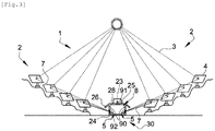
- Solar plant 1 of the figure 3 illustrates a specific configuration of a valley in a mountainous or hilly area located in a tropical or intertropical zone.
- the valley is here oriented East-West.
- the solar plant 1 is also in the form of a tunnel 30 resting on the ground.
- the reflection system 2 comprises two sets of reflectors 4 respectively arranged in a staircase on two slopes facing each other.
- the two sets of reflectors 4 are oriented so as to reflect respectively the incident solar rays 3 in the direction of two distinct points of convergence 5. More precisely, in this example the two points of convergence 5 are arranged at the level of two opposite side walls 90, and located in the lower part of the transformation chamber 8.
- the present invention also relates to a process for transforming raw material, using a solar plant 1.
- the process comprises a step of reflecting the incident solar rays 3 in the direction of at least one point of convergence 5. This orientation contribute to optimize the accumulation of solar thermal energy, the source of which is free, non-polluting and inexhaustible.
- the transformation process has a step of raising the temperature of the transformation chamber 8.
- the rise in temperature of the transformation chamber 8 results from its cooperation with the concentration and diffusion means 6 of the solar plant 1.
- the method also includes a step of conveying the raw material.
- the raw material is conveyed from the outside of the solar oven 1 to the processing chamber 8.
- the raw material is conveyed via a conveyor 10.
- the method comprises a step of gradual preheating of the raw material during transport to the processing chamber 8. This step is carried out using the heat exchanger (s) 23 which extends (ent ) between the inlet duct 17 and the outlet duct 18.
- the progressive preheating is carried out by a transfer of heat from the material transformed to the material to be transformed as described above.
- the process includes a step of transforming the raw material. This step takes place in the transformation chamber 8 at a defined temperature.
- the raw material is transformed by cooking, melting, thermal or photo thermal reaction, or thermo-catalysis, etc ...
- the transformation of the raw material can reside in a change of physical state or in thermo-catalysis a chemical reaction such as a polymerization and / or crosslinking reaction.
- the transformation method can comprise a step of adjusting the temperature of the transformation chamber 8. This adjustment step is carried out by varying the number of heliostats, or using the gas burner. The latter makes it possible to compensate for a loss of incident solar rays due for example to a cloudy passage.
- the transformation process can include a step of creating a reducing atmosphere. This step can be carried out by adding biogas within the enclosure of the transformation chamber 8.
- the addition of biogas reduces the supply of air into the enclosure of the transformation chamber 8 and makes it possible to reduce the material first.
- the addition of biogas can be carried out by a burner.
- the transformation process includes a step of removing the transformed material.
- the transformed material is then discharged from the transformation chamber 8 to the outside of the solar plant 1. As described above, the discharge of the raw material is carried out by the conveyor 10.
- solar plant 1 can be integrated into an industrial production line. On leaving solar plant 1, the transformed material can undergo further modifications made by other production and / or processing tools.
- the solar plant 1 advantageously makes it possible to catalyze or carry out a step of transformation of a raw material or of a pre-transformed material or of a precursor material.
Landscapes
- Engineering & Computer Science (AREA)
- Chemical & Material Sciences (AREA)
- Life Sciences & Earth Sciences (AREA)
- Sustainable Development (AREA)
- Sustainable Energy (AREA)
- Thermal Sciences (AREA)
- Physics & Mathematics (AREA)
- Combustion & Propulsion (AREA)
- Mechanical Engineering (AREA)
- General Engineering & Computer Science (AREA)
- Engine Equipment That Uses Special Cycles (AREA)
- Waste-Gas Treatment And Other Accessory Devices For Furnaces (AREA)
- Container, Conveyance, Adherence, Positioning, Of Wafer (AREA)
Applications Claiming Priority (1)
| Application Number | Priority Date | Filing Date | Title |
|---|---|---|---|
| FR1903290A FR3094465B1 (fr) | 2019-03-28 | 2019-03-28 | Usine solaire et procede de transformation |
Publications (2)
| Publication Number | Publication Date |
|---|---|
| EP3715744A1 true EP3715744A1 (de) | 2020-09-30 |
| EP3715744B1 EP3715744B1 (de) | 2021-11-24 |
Family
ID=67441405
Family Applications (1)
| Application Number | Title | Priority Date | Filing Date |
|---|---|---|---|
| EP20166861.3A Active EP3715744B1 (de) | 2019-03-28 | 2020-03-30 | Solarkraftwerk und umwandlungsverfahren |
Country Status (2)
| Country | Link |
|---|---|
| EP (1) | EP3715744B1 (de) |
| FR (1) | FR3094465B1 (de) |
Citations (6)
| Publication number | Priority date | Publication date | Assignee | Title |
|---|---|---|---|---|
| US4706651A (en) | 1986-02-24 | 1987-11-17 | The United States Of America As Represented By The United States Department Of Energy | Solar solids reactor |
| WO2014052902A1 (en) | 2012-09-30 | 2014-04-03 | Taber William Stevens Jr | Radiation collection utilizing total internal reflection and other techniques for the purpose of dispatchble electricity generation and other uses |
| US20140298822A1 (en) * | 2013-04-03 | 2014-10-09 | Alliance For Sustainable Energy, Llc | Chemical Looping Fluidized-Bed Concentrating Solar Power System and Method |
| US20150307960A1 (en) | 2013-01-09 | 2015-10-29 | Nikon Corporation | Magnesium refining apparatus and magnesium refining method |
| US20150308715A1 (en) * | 2012-12-28 | 2015-10-29 | Abengoa Solar Llc | Metal remelting with concentrated solar power |
| WO2015174236A1 (ja) | 2014-05-13 | 2015-11-19 | 国立大学法人新潟大学 | 集光太陽光の受熱装置、反応装置及び加熱装置 |
-
2019
- 2019-03-28 FR FR1903290A patent/FR3094465B1/fr not_active Expired - Fee Related
-
2020
- 2020-03-30 EP EP20166861.3A patent/EP3715744B1/de active Active
Patent Citations (6)
| Publication number | Priority date | Publication date | Assignee | Title |
|---|---|---|---|---|
| US4706651A (en) | 1986-02-24 | 1987-11-17 | The United States Of America As Represented By The United States Department Of Energy | Solar solids reactor |
| WO2014052902A1 (en) | 2012-09-30 | 2014-04-03 | Taber William Stevens Jr | Radiation collection utilizing total internal reflection and other techniques for the purpose of dispatchble electricity generation and other uses |
| US20150308715A1 (en) * | 2012-12-28 | 2015-10-29 | Abengoa Solar Llc | Metal remelting with concentrated solar power |
| US20150307960A1 (en) | 2013-01-09 | 2015-10-29 | Nikon Corporation | Magnesium refining apparatus and magnesium refining method |
| US20140298822A1 (en) * | 2013-04-03 | 2014-10-09 | Alliance For Sustainable Energy, Llc | Chemical Looping Fluidized-Bed Concentrating Solar Power System and Method |
| WO2015174236A1 (ja) | 2014-05-13 | 2015-11-19 | 国立大学法人新潟大学 | 集光太陽光の受熱装置、反応装置及び加熱装置 |
Also Published As
| Publication number | Publication date |
|---|---|
| FR3094465B1 (fr) | 2021-10-01 |
| EP3715744B1 (de) | 2021-11-24 |
| FR3094465A1 (fr) | 2020-10-02 |
Similar Documents
| Publication | Publication Date | Title |
|---|---|---|
| JP4420902B2 (ja) | 太陽エネルギー集積利用装置 | |
| Salvi et al. | Technological advances to maximize solar collector energy output: a review | |
| US20110209979A1 (en) | Chemical reactors with annularly positioned delivery and removal devices, and associated systems and methods | |
| CN102792022A (zh) | 会聚的太阳能电力系统 | |
| US5308187A (en) | Parking lot pavement for making hot precombustion air for a fossil fuel burner | |
| US20120298020A1 (en) | Gassification system | |
| Ma et al. | A review on solar concentrators with multi-surface and multi-element (MS/ME) combinations | |
| EP3715744B1 (de) | Solarkraftwerk und umwandlungsverfahren | |
| MA35047B1 (fr) | Tube récepteur de chaleur, procédé de fabrication de tube récepteur de chaleur, collecteur solaire à miroir cylindro-parabolique doté du tube récepteur, et utilisation du collecteur solaire à miroir cylindro-parabolique | |
| FR2530297A1 (fr) | Dispositif producteur d'energie par rotation d'une helice sous l'effet d'un deplacement d'air | |
| CN215252114U (zh) | 一种辅助沥青加热的装置及沥青罐 | |
| KR102462124B1 (ko) | 유동층 공정을 이용한 태양열 화학적 에너지 생산 장치 | |
| Weldekidan et al. | Performance evaluation of absorber reactors for solar fuel production | |
| CN201797463U (zh) | 负压膜结构旋转曲面聚光镜发电装置 | |
| KR101056941B1 (ko) | 접시형 태양열 집열장치 | |
| Emetere et al. | A short review on solar concentrator for energy generation in tropical coastal belt | |
| Kumar et al. | Performance of cylindrical parabolic solar collector with the tracking system | |
| JPS5997460A (ja) | 太陽光集光装置 | |
| US20230221070A1 (en) | System and method for the thermal processing of bulk material by intense concentrated solar power | |
| Chauhan et al. | Introduction and Fundamentals of Solar Energy Collectors | |
| CN119468512A (zh) | 一种塔式二次反射式光热烧制技术及控制方法 | |
| JP2004259783A (ja) | 太陽光発電装置 | |
| Desai et al. | Techniques for enhancing performance of parabolic trough systems: a review | |
| WO2016062804A2 (en) | Method and apparatus form operating a solar furnace 24 hours a day | |
| Lakshmipathy et al. | Influence of Cavity Materials and Selective Surface Coatings on the Performance of SCC |
Legal Events
| Date | Code | Title | Description |
|---|---|---|---|
| PUAI | Public reference made under article 153(3) epc to a published international application that has entered the european phase |
Free format text: ORIGINAL CODE: 0009012 |
|
| STAA | Information on the status of an ep patent application or granted ep patent |
Free format text: STATUS: THE APPLICATION HAS BEEN PUBLISHED |
|
| AK | Designated contracting states |
Kind code of ref document: A1 Designated state(s): AL AT BE BG CH CY CZ DE DK EE ES FI FR GB GR HR HU IE IS IT LI LT LU LV MC MK MT NL NO PL PT RO RS SE SI SK SM TR |
|
| AX | Request for extension of the european patent |
Extension state: BA ME |
|
| STAA | Information on the status of an ep patent application or granted ep patent |
Free format text: STATUS: REQUEST FOR EXAMINATION WAS MADE |
|
| 17P | Request for examination filed |
Effective date: 20210326 |
|
| RAV | Requested validation state of the european patent: fee paid |
Extension state: MA Effective date: 20210326 |
|
| RBV | Designated contracting states (corrected) |
Designated state(s): AL AT BE BG CH CY CZ DE DK EE ES FI FR GB GR HR HU IE IS IT LI LT LU LV MC MK MT NL NO PL PT RO RS SE SI SK SM TR |
|
| RIC1 | Information provided on ipc code assigned before grant |
Ipc: F24S 20/20 20180101AFI20210420BHEP Ipc: F24S 20/30 20180101ALI20210420BHEP Ipc: F26B 3/28 20060101ALI20210420BHEP |
|
| GRAP | Despatch of communication of intention to grant a patent |
Free format text: ORIGINAL CODE: EPIDOSNIGR1 |
|
| STAA | Information on the status of an ep patent application or granted ep patent |
Free format text: STATUS: GRANT OF PATENT IS INTENDED |
|
| INTG | Intention to grant announced |
Effective date: 20210707 |
|
| GRAA | (expected) grant |
Free format text: ORIGINAL CODE: 0009210 |
|
| STAA | Information on the status of an ep patent application or granted ep patent |
Free format text: STATUS: THE PATENT HAS BEEN GRANTED |
|
| GRAS | Grant fee paid |
Free format text: ORIGINAL CODE: EPIDOSNIGR3 |
|
| AK | Designated contracting states |
Kind code of ref document: B1 Designated state(s): AL AT BE BG CH CY CZ DE DK EE ES FI FR GB GR HR HU IE IS IT LI LT LU LV MC MK MT NL NO PL PT RO RS SE SI SK SM TR |
|
| REG | Reference to a national code |
Ref country code: GB Ref legal event code: FG4D Free format text: NOT ENGLISH |
|
| REG | Reference to a national code |
Ref country code: AT Ref legal event code: REF Ref document number: 1450151 Country of ref document: AT Kind code of ref document: T Effective date: 20211215 |
|
| REG | Reference to a national code |
Ref country code: IE Ref legal event code: FG4D Free format text: LANGUAGE OF EP DOCUMENT: FRENCH |
|
| REG | Reference to a national code |
Ref country code: DE Ref legal event code: R096 Ref document number: 602020001073 Country of ref document: DE |
|
| REG | Reference to a national code |
Ref country code: LT Ref legal event code: MG9D |
|
| REG | Reference to a national code |
Ref country code: NL Ref legal event code: MP Effective date: 20211124 |
|
| REG | Reference to a national code |
Ref country code: AT Ref legal event code: MK05 Ref document number: 1450151 Country of ref document: AT Kind code of ref document: T Effective date: 20211124 |
|
| PG25 | Lapsed in a contracting state [announced via postgrant information from national office to epo] |
Ref country code: RS Free format text: LAPSE BECAUSE OF FAILURE TO SUBMIT A TRANSLATION OF THE DESCRIPTION OR TO PAY THE FEE WITHIN THE PRESCRIBED TIME-LIMIT Effective date: 20211124 Ref country code: LT Free format text: LAPSE BECAUSE OF FAILURE TO SUBMIT A TRANSLATION OF THE DESCRIPTION OR TO PAY THE FEE WITHIN THE PRESCRIBED TIME-LIMIT Effective date: 20211124 Ref country code: FI Free format text: LAPSE BECAUSE OF FAILURE TO SUBMIT A TRANSLATION OF THE DESCRIPTION OR TO PAY THE FEE WITHIN THE PRESCRIBED TIME-LIMIT Effective date: 20211124 Ref country code: BG Free format text: LAPSE BECAUSE OF FAILURE TO SUBMIT A TRANSLATION OF THE DESCRIPTION OR TO PAY THE FEE WITHIN THE PRESCRIBED TIME-LIMIT Effective date: 20220224 Ref country code: AT Free format text: LAPSE BECAUSE OF FAILURE TO SUBMIT A TRANSLATION OF THE DESCRIPTION OR TO PAY THE FEE WITHIN THE PRESCRIBED TIME-LIMIT Effective date: 20211124 |
|
| PG25 | Lapsed in a contracting state [announced via postgrant information from national office to epo] |
Ref country code: IS Free format text: LAPSE BECAUSE OF FAILURE TO SUBMIT A TRANSLATION OF THE DESCRIPTION OR TO PAY THE FEE WITHIN THE PRESCRIBED TIME-LIMIT Effective date: 20220324 Ref country code: SE Free format text: LAPSE BECAUSE OF FAILURE TO SUBMIT A TRANSLATION OF THE DESCRIPTION OR TO PAY THE FEE WITHIN THE PRESCRIBED TIME-LIMIT Effective date: 20211124 Ref country code: PT Free format text: LAPSE BECAUSE OF FAILURE TO SUBMIT A TRANSLATION OF THE DESCRIPTION OR TO PAY THE FEE WITHIN THE PRESCRIBED TIME-LIMIT Effective date: 20220324 Ref country code: PL Free format text: LAPSE BECAUSE OF FAILURE TO SUBMIT A TRANSLATION OF THE DESCRIPTION OR TO PAY THE FEE WITHIN THE PRESCRIBED TIME-LIMIT Effective date: 20211124 Ref country code: NO Free format text: LAPSE BECAUSE OF FAILURE TO SUBMIT A TRANSLATION OF THE DESCRIPTION OR TO PAY THE FEE WITHIN THE PRESCRIBED TIME-LIMIT Effective date: 20220224 Ref country code: NL Free format text: LAPSE BECAUSE OF FAILURE TO SUBMIT A TRANSLATION OF THE DESCRIPTION OR TO PAY THE FEE WITHIN THE PRESCRIBED TIME-LIMIT Effective date: 20211124 Ref country code: LV Free format text: LAPSE BECAUSE OF FAILURE TO SUBMIT A TRANSLATION OF THE DESCRIPTION OR TO PAY THE FEE WITHIN THE PRESCRIBED TIME-LIMIT Effective date: 20211124 Ref country code: HR Free format text: LAPSE BECAUSE OF FAILURE TO SUBMIT A TRANSLATION OF THE DESCRIPTION OR TO PAY THE FEE WITHIN THE PRESCRIBED TIME-LIMIT Effective date: 20211124 Ref country code: GR Free format text: LAPSE BECAUSE OF FAILURE TO SUBMIT A TRANSLATION OF THE DESCRIPTION OR TO PAY THE FEE WITHIN THE PRESCRIBED TIME-LIMIT Effective date: 20220225 |
|
| PG25 | Lapsed in a contracting state [announced via postgrant information from national office to epo] |
Ref country code: SM Free format text: LAPSE BECAUSE OF FAILURE TO SUBMIT A TRANSLATION OF THE DESCRIPTION OR TO PAY THE FEE WITHIN THE PRESCRIBED TIME-LIMIT Effective date: 20211124 Ref country code: SK Free format text: LAPSE BECAUSE OF FAILURE TO SUBMIT A TRANSLATION OF THE DESCRIPTION OR TO PAY THE FEE WITHIN THE PRESCRIBED TIME-LIMIT Effective date: 20211124 Ref country code: RO Free format text: LAPSE BECAUSE OF FAILURE TO SUBMIT A TRANSLATION OF THE DESCRIPTION OR TO PAY THE FEE WITHIN THE PRESCRIBED TIME-LIMIT Effective date: 20211124 Ref country code: ES Free format text: LAPSE BECAUSE OF FAILURE TO SUBMIT A TRANSLATION OF THE DESCRIPTION OR TO PAY THE FEE WITHIN THE PRESCRIBED TIME-LIMIT Effective date: 20211124 Ref country code: EE Free format text: LAPSE BECAUSE OF FAILURE TO SUBMIT A TRANSLATION OF THE DESCRIPTION OR TO PAY THE FEE WITHIN THE PRESCRIBED TIME-LIMIT Effective date: 20211124 Ref country code: DK Free format text: LAPSE BECAUSE OF FAILURE TO SUBMIT A TRANSLATION OF THE DESCRIPTION OR TO PAY THE FEE WITHIN THE PRESCRIBED TIME-LIMIT Effective date: 20211124 Ref country code: CZ Free format text: LAPSE BECAUSE OF FAILURE TO SUBMIT A TRANSLATION OF THE DESCRIPTION OR TO PAY THE FEE WITHIN THE PRESCRIBED TIME-LIMIT Effective date: 20211124 |
|
| REG | Reference to a national code |
Ref country code: DE Ref legal event code: R097 Ref document number: 602020001073 Country of ref document: DE |
|
| PLBE | No opposition filed within time limit |
Free format text: ORIGINAL CODE: 0009261 |
|
| STAA | Information on the status of an ep patent application or granted ep patent |
Free format text: STATUS: NO OPPOSITION FILED WITHIN TIME LIMIT |
|
| PG25 | Lapsed in a contracting state [announced via postgrant information from national office to epo] |
Ref country code: AL Free format text: LAPSE BECAUSE OF FAILURE TO SUBMIT A TRANSLATION OF THE DESCRIPTION OR TO PAY THE FEE WITHIN THE PRESCRIBED TIME-LIMIT Effective date: 20211124 |
|
| 26N | No opposition filed |
Effective date: 20220825 |
|
| PG25 | Lapsed in a contracting state [announced via postgrant information from national office to epo] |
Ref country code: SI Free format text: LAPSE BECAUSE OF FAILURE TO SUBMIT A TRANSLATION OF THE DESCRIPTION OR TO PAY THE FEE WITHIN THE PRESCRIBED TIME-LIMIT Effective date: 20211124 |
|
| PG25 | Lapsed in a contracting state [announced via postgrant information from national office to epo] |
Ref country code: LU Free format text: LAPSE BECAUSE OF NON-PAYMENT OF DUE FEES Effective date: 20220330 Ref country code: IE Free format text: LAPSE BECAUSE OF NON-PAYMENT OF DUE FEES Effective date: 20220330 |
|
| PG25 | Lapsed in a contracting state [announced via postgrant information from national office to epo] |
Ref country code: IT Free format text: LAPSE BECAUSE OF FAILURE TO SUBMIT A TRANSLATION OF THE DESCRIPTION OR TO PAY THE FEE WITHIN THE PRESCRIBED TIME-LIMIT Effective date: 20211124 |
|
| PGFP | Annual fee paid to national office [announced via postgrant information from national office to epo] |
Ref country code: MC Payment date: 20240329 Year of fee payment: 5 |
|
| PG25 | Lapsed in a contracting state [announced via postgrant information from national office to epo] |
Ref country code: MK Free format text: LAPSE BECAUSE OF FAILURE TO SUBMIT A TRANSLATION OF THE DESCRIPTION OR TO PAY THE FEE WITHIN THE PRESCRIBED TIME-LIMIT Effective date: 20211124 Ref country code: CY Free format text: LAPSE BECAUSE OF FAILURE TO SUBMIT A TRANSLATION OF THE DESCRIPTION OR TO PAY THE FEE WITHIN THE PRESCRIBED TIME-LIMIT Effective date: 20211124 |
|
| PGFP | Annual fee paid to national office [announced via postgrant information from national office to epo] |
Ref country code: GB Payment date: 20240328 Year of fee payment: 5 |
|
| VS25 | Lapsed in a validation state [announced via postgrant information from nat. office to epo] |
Ref country code: MA Free format text: LAPSE BECAUSE OF FAILURE TO SUBMIT A TRANSLATION OF THE DESCRIPTION OR TO PAY THE FEE WITHIN THE PRESCRIBED TIME-LIMIT Effective date: 20211124 |
|
| PG25 | Lapsed in a contracting state [announced via postgrant information from national office to epo] |
Ref country code: HU Free format text: LAPSE BECAUSE OF FAILURE TO SUBMIT A TRANSLATION OF THE DESCRIPTION OR TO PAY THE FEE WITHIN THE PRESCRIBED TIME-LIMIT; INVALID AB INITIO Effective date: 20200330 |
|
| PGFP | Annual fee paid to national office [announced via postgrant information from national office to epo] |
Ref country code: FR Payment date: 20240227 Year of fee payment: 5 Ref country code: BE Payment date: 20240328 Year of fee payment: 5 |
|
| PG25 | Lapsed in a contracting state [announced via postgrant information from national office to epo] |
Ref country code: TR Free format text: LAPSE BECAUSE OF FAILURE TO SUBMIT A TRANSLATION OF THE DESCRIPTION OR TO PAY THE FEE WITHIN THE PRESCRIBED TIME-LIMIT Effective date: 20211124 |
|
| PGFP | Annual fee paid to national office [announced via postgrant information from national office to epo] |
Ref country code: DE Payment date: 20240426 Year of fee payment: 5 |
|
| PGFP | Annual fee paid to national office [announced via postgrant information from national office to epo] |
Ref country code: CH Payment date: 20240404 Year of fee payment: 5 |
|
| PG25 | Lapsed in a contracting state [announced via postgrant information from national office to epo] |
Ref country code: MT Free format text: LAPSE BECAUSE OF FAILURE TO SUBMIT A TRANSLATION OF THE DESCRIPTION OR TO PAY THE FEE WITHIN THE PRESCRIBED TIME-LIMIT Effective date: 20211124 |
|
| REG | Reference to a national code |
Ref country code: DE Ref legal event code: R119 Ref document number: 602020001073 Country of ref document: DE |
|
| PG25 | Lapsed in a contracting state [announced via postgrant information from national office to epo] |
Ref country code: MC Free format text: LAPSE BECAUSE OF NON-PAYMENT OF DUE FEES Effective date: 20250331 |
|
| REG | Reference to a national code |
Ref country code: CH Ref legal event code: H13 Free format text: ST27 STATUS EVENT CODE: U-0-0-H10-H13 (AS PROVIDED BY THE NATIONAL OFFICE) Effective date: 20251023 |
|
| GBPC | Gb: european patent ceased through non-payment of renewal fee |
Effective date: 20250330 |
|
| REG | Reference to a national code |
Ref country code: BE Ref legal event code: MM Effective date: 20250331 |
|
| PG25 | Lapsed in a contracting state [announced via postgrant information from national office to epo] |
Ref country code: DE Free format text: LAPSE BECAUSE OF NON-PAYMENT OF DUE FEES Effective date: 20251001 |
|
| PG25 | Lapsed in a contracting state [announced via postgrant information from national office to epo] |
Ref country code: GB Free format text: LAPSE BECAUSE OF NON-PAYMENT OF DUE FEES Effective date: 20250330 |
|
| PG25 | Lapsed in a contracting state [announced via postgrant information from national office to epo] |
Ref country code: FR Free format text: LAPSE BECAUSE OF NON-PAYMENT OF DUE FEES Effective date: 20250331 |
|
| PG25 | Lapsed in a contracting state [announced via postgrant information from national office to epo] |
Ref country code: BE Free format text: LAPSE BECAUSE OF NON-PAYMENT OF DUE FEES Effective date: 20250331 |
|
| PG25 | Lapsed in a contracting state [announced via postgrant information from national office to epo] |
Ref country code: CH Free format text: LAPSE BECAUSE OF NON-PAYMENT OF DUE FEES Effective date: 20250331 |