EP3715584B1 - Silencieux de pompe pneumatique, pompe pneumatique comprenant un tel silencieux et installation de projection de produit de revêtement comportant au moins une telle pompe pneumatique - Google Patents
Silencieux de pompe pneumatique, pompe pneumatique comprenant un tel silencieux et installation de projection de produit de revêtement comportant au moins une telle pompe pneumatique Download PDFInfo
- Publication number
- EP3715584B1 EP3715584B1 EP20166135.2A EP20166135A EP3715584B1 EP 3715584 B1 EP3715584 B1 EP 3715584B1 EP 20166135 A EP20166135 A EP 20166135A EP 3715584 B1 EP3715584 B1 EP 3715584B1
- Authority
- EP
- European Patent Office
- Prior art keywords
- air
- pump
- silencer
- pneumatic pump
- pneumatic
- Prior art date
- Legal status (The legal status is an assumption and is not a legal conclusion. Google has not performed a legal analysis and makes no representation as to the accuracy of the status listed.)
- Active
Links
Images


Classifications
-
- F—MECHANICAL ENGINEERING; LIGHTING; HEATING; WEAPONS; BLASTING
- F04—POSITIVE - DISPLACEMENT MACHINES FOR LIQUIDS; PUMPS FOR LIQUIDS OR ELASTIC FLUIDS
- F04B—POSITIVE-DISPLACEMENT MACHINES FOR LIQUIDS; PUMPS
- F04B39/00—Component parts, details, or accessories, of pumps or pumping systems specially adapted for elastic fluids, not otherwise provided for in, or of interest apart from, groups F04B25/00 - F04B37/00
- F04B39/0027—Pulsation and noise damping means
- F04B39/005—Pulsation and noise damping means with direct action on the fluid flow using absorptive materials
-
- F—MECHANICAL ENGINEERING; LIGHTING; HEATING; WEAPONS; BLASTING
- F04—POSITIVE - DISPLACEMENT MACHINES FOR LIQUIDS; PUMPS FOR LIQUIDS OR ELASTIC FLUIDS
- F04B—POSITIVE-DISPLACEMENT MACHINES FOR LIQUIDS; PUMPS
- F04B39/00—Component parts, details, or accessories, of pumps or pumping systems specially adapted for elastic fluids, not otherwise provided for in, or of interest apart from, groups F04B25/00 - F04B37/00
- F04B39/0027—Pulsation and noise damping means
- F04B39/0083—Pulsation and noise damping means using blow off silencers
-
- F—MECHANICAL ENGINEERING; LIGHTING; HEATING; WEAPONS; BLASTING
- F04—POSITIVE - DISPLACEMENT MACHINES FOR LIQUIDS; PUMPS FOR LIQUIDS OR ELASTIC FLUIDS
- F04B—POSITIVE-DISPLACEMENT MACHINES FOR LIQUIDS; PUMPS
- F04B39/00—Component parts, details, or accessories, of pumps or pumping systems specially adapted for elastic fluids, not otherwise provided for in, or of interest apart from, groups F04B25/00 - F04B37/00
- F04B39/0027—Pulsation and noise damping means
-
- B—PERFORMING OPERATIONS; TRANSPORTING
- B05—SPRAYING OR ATOMISING IN GENERAL; APPLYING FLUENT MATERIALS TO SURFACES, IN GENERAL
- B05B—SPRAYING APPARATUS; ATOMISING APPARATUS; NOZZLES
- B05B9/00—Spraying apparatus for discharge of liquids or other fluent material, without essentially mixing with gas or vapour
- B05B9/03—Spraying apparatus for discharge of liquids or other fluent material, without essentially mixing with gas or vapour characterised by means for supplying liquid or other fluent material
- B05B9/04—Spraying apparatus for discharge of liquids or other fluent material, without essentially mixing with gas or vapour characterised by means for supplying liquid or other fluent material with pressurised or compressible container; with pump
- B05B9/0403—Spraying apparatus for discharge of liquids or other fluent material, without essentially mixing with gas or vapour characterised by means for supplying liquid or other fluent material with pressurised or compressible container; with pump with pumps for liquids or other fluent material
- B05B9/0409—Spraying apparatus for discharge of liquids or other fluent material, without essentially mixing with gas or vapour characterised by means for supplying liquid or other fluent material with pressurised or compressible container; with pump with pumps for liquids or other fluent material the pumps being driven by a hydraulic or a pneumatic fluid
-
- B—PERFORMING OPERATIONS; TRANSPORTING
- B05—SPRAYING OR ATOMISING IN GENERAL; APPLYING FLUENT MATERIALS TO SURFACES, IN GENERAL
- B05B—SPRAYING APPARATUS; ATOMISING APPARATUS; NOZZLES
- B05B9/00—Spraying apparatus for discharge of liquids or other fluent material, without essentially mixing with gas or vapour
- B05B9/03—Spraying apparatus for discharge of liquids or other fluent material, without essentially mixing with gas or vapour characterised by means for supplying liquid or other fluent material
- B05B9/04—Spraying apparatus for discharge of liquids or other fluent material, without essentially mixing with gas or vapour characterised by means for supplying liquid or other fluent material with pressurised or compressible container; with pump
- B05B9/08—Apparatus to be carried on or by a person, e.g. of knapsack type
- B05B9/085—Apparatus to be carried on or by a person, e.g. of knapsack type with a liquid pump
-
- F—MECHANICAL ENGINEERING; LIGHTING; HEATING; WEAPONS; BLASTING
- F01—MACHINES OR ENGINES IN GENERAL; ENGINE PLANTS IN GENERAL; STEAM ENGINES
- F01B—MACHINES OR ENGINES, IN GENERAL OR OF POSITIVE-DISPLACEMENT TYPE, e.g. STEAM ENGINES
- F01B31/00—Component parts, details or accessories not provided for in, or of interest apart from, other groups
- F01B31/005—Silencing equipment
-
- F—MECHANICAL ENGINEERING; LIGHTING; HEATING; WEAPONS; BLASTING
- F02—COMBUSTION ENGINES; HOT-GAS OR COMBUSTION-PRODUCT ENGINE PLANTS
- F02B—INTERNAL-COMBUSTION PISTON ENGINES; COMBUSTION ENGINES IN GENERAL
- F02B77/00—Component parts, details or accessories, not otherwise provided for
- F02B77/11—Thermal or acoustic insulation
- F02B77/13—Acoustic insulation
-
- F—MECHANICAL ENGINEERING; LIGHTING; HEATING; WEAPONS; BLASTING
- F04—POSITIVE - DISPLACEMENT MACHINES FOR LIQUIDS; PUMPS FOR LIQUIDS OR ELASTIC FLUIDS
- F04B—POSITIVE-DISPLACEMENT MACHINES FOR LIQUIDS; PUMPS
- F04B17/00—Pumps characterised by combination with, or adaptation to, specific driving engines or motors
-
- F—MECHANICAL ENGINEERING; LIGHTING; HEATING; WEAPONS; BLASTING
- F04—POSITIVE - DISPLACEMENT MACHINES FOR LIQUIDS; PUMPS FOR LIQUIDS OR ELASTIC FLUIDS
- F04B—POSITIVE-DISPLACEMENT MACHINES FOR LIQUIDS; PUMPS
- F04B37/00—Pumps having pertinent characteristics not provided for in, or of interest apart from, groups F04B25/00 - F04B35/00
- F04B37/10—Pumps having pertinent characteristics not provided for in, or of interest apart from, groups F04B25/00 - F04B35/00 for special use
- F04B37/18—Pumps having pertinent characteristics not provided for in, or of interest apart from, groups F04B25/00 - F04B35/00 for special use for specific elastic fluids
- F04B37/20—Pumps having pertinent characteristics not provided for in, or of interest apart from, groups F04B25/00 - F04B35/00 for special use for specific elastic fluids for wet gases, e.g. wet air
-
- G—PHYSICS
- G10—MUSICAL INSTRUMENTS; ACOUSTICS
- G10K—SOUND-PRODUCING DEVICES; METHODS OR DEVICES FOR PROTECTING AGAINST, OR FOR DAMPING, NOISE OR OTHER ACOUSTIC WAVES IN GENERAL; ACOUSTICS NOT OTHERWISE PROVIDED FOR
- G10K11/00—Methods or devices for transmitting, conducting or directing sound in general; Methods or devices for protecting against, or for damping, noise or other acoustic waves in general
- G10K11/16—Methods or devices for protecting against, or for damping, noise or other acoustic waves in general
- G10K11/162—Selection of materials
-
- F—MECHANICAL ENGINEERING; LIGHTING; HEATING; WEAPONS; BLASTING
- F05—INDEXING SCHEMES RELATING TO ENGINES OR PUMPS IN VARIOUS SUBCLASSES OF CLASSES F01-F04
- F05B—INDEXING SCHEME RELATING TO WIND, SPRING, WEIGHT, INERTIA OR LIKE MOTORS, TO MACHINES OR ENGINES FOR LIQUIDS COVERED BY SUBCLASSES F03B, F03D AND F03G
- F05B2260/00—Function
- F05B2260/96—Preventing, counteracting or reducing vibration or noise
- F05B2260/962—Preventing, counteracting or reducing vibration or noise by means creating "anti-noise"
Definitions
- the present invention relates to a pneumatic pump silencer, comprising a body defining an interior volume and having at least one wall comprising an air outlet orifice, this pneumatic pump silencer further comprising a damping pad with a face. arranged opposite the air outlet orifice.
- pneumatic pumps have an air motor driven by compressed air.
- Pneumatic piston pumps generally comprise two chambers of variable volume arranged around a piston mounted on a shaft, these two chambers of variable volume being alternately supplied with compressed air and connected to an air exhaust, to move the piston. in a reciprocating motion. The movement of the piston is picked up by the shaft and is used to drive other equipment, such as a liquid coating product pump.
- the humidity in the air may condense and accumulate in the manifold and in the muffler.
- the air pump manifold and muffler may be subject to icing, which reduces the passage area of the exhaust air and reduces the performance of the pump. pneumatic.
- the invention more particularly intends to remedy, by proposing a pneumatic pump silencer avoiding accumulation of condensation water, not subject to icing, even in the event of intensive use, and sufficiently compact to be integrated into the air pump casing.
- the invention relates to a pneumatic pump silencer of the aforementioned type, in which a gap is formed between the face of the attenuation pad and an outer face of the wall comprising the air outlet orifice, this gap having a thickness between 0.5 mm and 5 mm.
- the pneumatic pump muffler allows better evacuation of condensation water to the outside of the muffler, which prevents icing of the muffler and guarantees long-lasting reverse performance under heavy use.
- the exhaust of the pneumatic pump is not choked, which guarantees clear reversals and better comfort of use.
- the invention also relates to a coating product spraying installation comprising at least one pneumatic pump as mentioned above, as well as a coating product pump driven by this pneumatic pump.
- This coating product spraying installation offers the same effects as those mentioned above with regard to the pneumatic pump silencer of the invention.
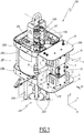
- a pneumatic pump 100 is shown in figure 1 .
- This pneumatic pump 100 is shown here in a mounted configuration, certain elements having been omitted to facilitate understanding of the operation of the pneumatic pump 100.
- the pneumatic pump 100 comprises a pump cylinder 105 of circular section and oriented along an axis Z105 parallel to the Z axis.
- the pump cylinder 105 is closed at one end by a high cover 105A and at the other end by a low cover 105B.
- the top 105A and bottom 105B covers are of similar structure and arranged opposite one another at the two ends of the pump cylinder 105.
- Each cover has an internal part 105D, this internal part 105D being of circular section and specific to be inserted into the pump cylinder 105, this insertion being sealed by means of O-rings 105J.
- Each cover 105A and 105B further comprises an external part 105E.
- the face of each external part 105E the normal of which is parallel to the Z axis and away from the cylinder 105, comprises several bosses which are themselves bored, suitable for accommodating various fasteners such as screws.
- the bored bosses of the bottom cover 105B receive metal rods 107A, these rods 107A forming a frame of a pump for liquid product 204 belonging to a spraying installation 200 shown in FIG. figure 5 and which comprises, in addition to the pneumatic pump 100 and the pump 204 for liquid product, a sprayer 206 and a pipe 208 fluidly connecting the pump 204 to the sprayer 206 for transferring the liquid product from the pump 204 to the sprayer 206.
- the sprayer 206 intended to project a liquid product onto a target surface, not shown in the figures, is for example a manual gun as can be seen in the figure. figure 5 , or an automatic sprayer, known per se.
- the sprayer is preferably of the “airless” type, that is to say capable of spraying the liquid product without adding spray air. In this sense, the installation 200 is an airless type installation. To do this, the pressure of the liquid product supplied by the pump 4 to the sprayer 6 must be high, for example greater than 30 bars.
- the pump 204 for liquid product comprises a body 215 in which is formed a suction or inlet opening 212 for sucking the liquid product and a delivery or outlet opening 210 for injecting the liquid product to the sprayer 206 through the tube. pipe 208.
- the inlet opening 202 is for example equipped with a valve, not shown.
- the inlet opening 212 is fluidly connected to a reservoir 207 of liquid product, through a pipe 209.
- the body 215 internally delimits a cylindrical compression chamber, in which a piston (not shown) is mounted to slide along an axis parallel to the axis Z.
- the piston of the pump 204 for liquid product is integral with a piston 104 of the pneumatic pump. 100 and connected to it by a shaft 106, that is to say that the pump 204 for liquid product is driven by the pneumatic pump 100.
- top covers 105A and bottom cover 105B are held in place by fixing rods 105C.
- the pneumatic pump 100 also includes the piston 104 located inside the pump cylinder 105.
- the piston 104 is mounted on the shaft 106 whose axis is the axis Z105.
- the shaft 106 passes through the top cover 105A and the bottom cover 105B, the seal between the shaft 106 and the top cover 105A and bottom cover 105B being ensured by sealing members not detailed below.
- the piston 104 is inserted into the pump cylinder 105, a seal 104J mounted at the periphery of the piston 104 ensuring the sealing of contact with the pump cylinder 105.
- the volume defined by the pump cylinder. pump 105, piston 104 and top cover 105A is referred to as upper chamber 102A and, similarly, the volume defined by pump cylinder 105, piston 104, and bottom cover 105B is referred to as lower chamber 102B.
- the piston 104 being movable in translation along the axis Z105, the position of the piston 104 within the pump cylinder 105 changes and thereby the volume of the upper chambers 102A and lower chamber 102B also changes.
- the upper chamber 102A and lower chamber 102B are therefore chambers of variable volume.
- a high duct 112A is provided in the high cover 105A.
- One end of the top duct 112A opens out from the internal part 105D of the top cover 105A into the upper chamber 102A.
- the other end of the top duct 112A opens out from the external part 105E on a side face of the top cover 105A in a direction parallel to the X axis and away from the Z105 axis.
- a low duct 112B is provided in the low cover 105B.
- One end of the bottom duct 112B opens out from the internal part 105D of the bottom cover 105B into the lower chamber 102B.
- the other end of the bottom duct 112B opens out from the external part 105E on a side face of the bottom cover 105B in a direction parallel to the X axis and away from the Z105 axis.
- a contactor bracket 110 is attached to the outer part 105E of the top cover 105A.
- the contactor support 110 is in the form of an elongated rectangular plate, the long side of which is oriented along the Z axis, the contactor support 110 being oriented perpendicular to the direction of the Y axis.
- the contactor support 110 has a lower end, close to the top cover 105A, and an upper end, further away from the top cover 105A.
- a low contactor 110B is attached to the contactor bracket 110 near its lower end and a high contactor 110A is attached to the contactor bracket 110 near its high end.
- the high switch 110A and low switch 110B each have a lever 111 and a backing roller 111A.
- the pneumatic pump 100 also includes a casing 114
- the casing 114 consists of a bottom 114A, a high rim 114B and a low rim 114C.
- the bottom 114A is flat, arranged in the plane of the Z and Y axes, that is to say normal to the X axis.
- the top flange 114B and bottom flange 114C extend facing each other. , perpendicular to the bottom 144A, in the X direction.
- the bottom 114A, the top rim 114B and the bottom rim 114C define a housing, the interior volume of which is denoted V114.
- a low passage 116B is formed in the bottom 114A of the casing 114 in the vicinity of the low rim 114C. Holes 120 with axes parallel to the X axis are arranged on either side, in the Y direction, of the bottom passage 116B. Similarly, a top passage 116A is also provided in the bottom 114A of the casing 114 in the vicinity of the top rim 114B. Bores 120 are also provided in the bottom 114A on either side of the top passage 116A.
- the pneumatic pump 100 also comprises a member 2 for supplying air.
- the member 2 has a free end 2A, intended to be connected to an external compressed air source, such as a compressor or a tank, not represented.
- the compressed air generates the reciprocating movement of the piston 104 and of the shaft 106.
- the air supply member 2 has another end 2B, connected to a base 4.
- the base 4 has a generally parallelepipedal shape, of which the faces are orthogonal to the X, Y and Z axes.
- the base 4 has, on one of the faces normal to the X axis, a plate 4A, from which several air ducts and passages open. From bottom to top, there is thus a bottom exhaust duct 43B, a bottom air passage 42B, an air inlet conduit 41, a top air passage 42A and a top exhaust conduit 43A.
- top 42A and bottom 42B air passages each have one end opening onto the plate 4A, the other respective end of the top 42A and bottom 42B air passages opening out of the base 4 via the face opposite to the bottom.
- plate 4A that is to say the face oriented towards the housing 114, facing the top 116A and bottom 116B passages, respectively.
- the top 43A and bottom 43B exhaust ducts each have one end opening onto the plate 4A, the other end being a top 44A or bottom 44B air exhaust port, provided respectively in the upper or lower side of the plate. 4A and parallel to the Z axis.
- the air inlet duct 41 opens at one end on the plate 4A and at the other end on one of the side faces of the plate 4A, normal to the Y axis.
- Bores 4B are furthermore formed on the plate 4A, the axes of these bores 4B being parallel to the axis X.
- Through holes 46 are formed in the base 4 in the vicinity of the upper and lower faces, the axis of these bores. through holes being parallel to the X axis.
- An air distributor 12 is arranged opposite the plate 4A.
- This air distributor 12 has a generally parallelepipedal shape, the faces of which are normal to the X, Y and Z axes.
- the air distributor 12 has bores, not referenced, parallel to the X axis and suitable for receiving screws. mounting bracket 12A.
- the dispenser 6 which is known per se, is shown in exterior view on figure 2 .
- the piston 104 is in a so-called low position, that is to say that the piston 104 is in abutment against the bottom cover 105B, the lower chamber 102B then has a minimum volume and the upper chamber 102A a maximum volume.
- a cam 108 is fixed to the shaft 106 and therefore follows the same upward reciprocating movements, along arrow F1, or downward, along arrow F2. In low position as shown in figure 2 , the cam 108 is in contact with the support roller 111A of the bottom contactor 110B.
- the low contactor 110B and the high contactor 110A have a similar structure, with a support roller 111A fixed to a lever 111, the lever 111 itself being linked to the body of the high 110A or low 110B contactor.
- the up and down contactors 110A and 110B operate as valves, allowing compressed air to pass when the backing roller 111A is moved and interrupting the passage when the backing roller 111A is in its nominal position.
- the air circuits for controlling the up and down contactors are not shown in the figures of the present description.
- the cam 108 moves on the support roller 111A of the bottom contactor 110B.
- the role of the air distributor 12 is to distribute the air coming from the air inlet duct 41 to one of the top air passage 42A or bottom 42B and simultaneously to connect the other of the top air passage 42A and bottom 42B to the corresponding exhaust duct, that is to say, in the case of the top air passage 42A, to the top exhaust duct 43A and, in the case of the bottom air passage 42B, to the bottom exhaust duct 43B.
- the air distributor 12 is pneumatically controlled by compressed air control circuits connected to each of the high 110A and low 110B contactors.
- the air distributor 12 When the pneumatic pump 100 is mounted, the air distributor 12 is fixed to the plate 4A of the base 4 by means of the fixing screws 12A cooperating with the bores 4B formed in the plate 4A.
- the air distributor 12 thus mounted on the base 4 and the base 4 together define an air distribution sub-assembly 14.
- the air distribution sub-assembly 14 When the pneumatic pump 100 is mounted, the air distribution sub-assembly 14 is placed in the interior volume V114 of the casing 114, the top air passage 42A then being aligned with the top passage 116A formed in the bottom 114A of the housing. housing 114 and the top duct 112A formed in the top cover 105A.
- the bottom air passage 42B of the base 4 is then aligned with the bottom passage 116B of the bottom 114A of the housing 114 and the bottom duct 112B of the bottom cover 105B.
- the assembly of the air distribution sub-assembly 14, the casing 114 and the top cover 105A and bottom cover 105B includes sealing members capable of ensuring a sealed connection between the top air passage 42A, the top passage 116A and the top duct 112A on the one hand and between the bottom air passage 42B, the bottom passage 116B and the bottom duct 112B on the other hand.
- the pneumatic control sent by the low switch 110B controls the air distributor 12 and, as a result, the duct air inlet 41 is connected to the bottom air passage 42B through the air distributor 12 and the top air passage 42A is connected to the top exhaust duct 43A.
- the upper chamber 102A is then connected, via the top duct 112A, the top passage 116A and the top air passage 42A, to the top exhaust duct 43A and thus to the air exhaust port. 44A.
- the pressure therein is then substantially equal to atmospheric pressure.
- the piston 104A moves along the Z105 axis in the direction of the arrow F1, i.e. upwards.
- the upper chamber 102A is still at the pressure of the compressed air coming from the air inlet duct.
- the upper chamber 102A suddenly finds itself connected to the air exhaust port 44, causing the exhaust air to expand suddenly, which results in noise. potentially significant and cooling associated with the decompression of the compressed air.
- Compressed air naturally moves from areas of high pressure to areas of low pressure. More generally when one of the variable volume chambers 102A and 102B, initially under pressure, is connected to one of the top 43A or bottom 43B exhaust ducts, the flow of the compressed air takes place in the respectively in the direction of arrows F3 or F4 up to the level of the air exhaust ports 44A or 44B. This direction of flow defines the downstream direction with respect to each air exhaust port 44A or 44B.
- the piston 104 After the inversion of the air distributor 12, the piston 104 therefore moves upwards, until the cam 108 reaches the support roller 111A of the top contactor 110A.
- the air distributor 12 Under the effect of the pneumatic control signal transmitted by the high switch 110A to the air distributor 12, the air distributor 12 is reversed again.
- the lower chamber 102B which was previously connected to the air supply 2 via the lower duct 112B, the lower passage 116B and the lower air passage 42B, suddenly finds itself linked to the exhaust duct bottom 43B, itself linked to the air exhaust port 44B.
- the upper chamber 102A which was until then in an exhaust situation, is found connected to the air supply 2 via the various passages already described.
- the pneumatic pump further comprises a layer of foam 20 and a perforated cover 21.
- the layer of foam 20 is in the form of a plate of thickness E20.
- the pneumatic pump 100 further comprises two pneumatic pump mufflers 1.
- a pneumatic pump silencer 1 comprises a body 6, of generally cubic shape, the faces of which are normal to the axes X, Y and Z.
- the body 6 is hollowed out and defines an internal volume V6.
- the interior volume V6 opens onto two of the faces of the body 6, these faces being adjacent, the normal of one of them being parallel to the X axis and oriented towards the casing, the normal of the other face being parallel to the Z axis.
- the body 6 has two side walls 62 normal to the Y axis. 62A denotes the outer face of each side wall 62, that is to say the face whose normal along Y moves away from body 6.
- An air outlet orifice 64 is provided in each side wall 62, that is to say that the air outlet orifice 64 passes through the wall 62 and opens into the interior volume V6 and to the exterior of the body 6.
- An air outlet orifice 64 is provided substantially centered on the corresponding side wall 62.
- the body 6 further comprises a solid wall 65 and a front wall 68.
- the solid wall 65 is normal to the Z axis and the front wall is parallel to the Y and Z axes.
- the normal to the front wall 68 is parallel to the X axis and away from the housing.
- Two through holes 68A are also formed in the front wall 68 parallel to the X axis, these holes 68A passing through the body 6 in the thickness of the solid wall 65.
- the side walls 62 are also pierced with bore 66 oriented parallel to the Y axis, these bores 66 also being formed in the thickness of the solid wall 65.
- Each pneumatic pump silencer 1 also includes two attenuation pads 8, these attenuation pads 8 consisting of identical parallelepiped-shaped plates whose faces are normal to the X, Y and Z axes. E8 the thickness of a pad 8 measured along the Y axis.
- An attenuation pad 8 has a first face 8A normal to the Y axis, as well as a second upper face 8B and a third lower face 8C, these faces 8B and 8C being normal to the Z axis.
- Two through holes 82 are formed in the first face 8A of the pad 8 in the vicinity of the edge between the first face of the pad 8A and the second face 8B.
- guide notches 81 are formed in the first face 8A of the pad 8 in the vicinity of the third face 8C, these guide notches having a rectangular section in the plane normal to the Y axis.
- Each pneumatic pump silencer 1 also comprises two identical supports 16.
- Each support 16 comprises a bottom 16A of rectangular shape, oriented perpendicular to the Y axis.
- a support 16 On one of the ridges parallel to the X axis of the bottom 16A, a support 16 comprises a support rim 16B, the support rim 16B being parallel to the X and Y axes and, on the other edge parallel to X of the bottom 16A, this support 16 comprises two spacer feet 16C oriented parallel to the axis Y on the same side of the bottom 16A as the support rim 16B.
- the spacer feet 16C have, in the plane orthogonal to the Y axis, a substantially rectangular section.
- the end of the support flange 16B and the ends of the spacer legs 16C are normal to the Y axis and are, moreover, in the same plane parallel to the X and Z axes.
- the bottom 16A of a support 16 , its bearing flange 16B and its spacer feet 16C define a volume V16 for receiving a pad 8 and P16 denotes the depth of the volume 16, measured parallel to the Y axis.
- Through holes 16D are furthermore formed in the bottom 16A of each support 16 parallel to the Y axis, in the vicinity of the edge between the bottom 16A and the bearing flange 16B, these through holes 16D opening into the reception volume V16.
- Each pump silencer 1 further comprises first screws 18A and second screws 18B, the first screws 18A being shorter than the second screws 18B.
- each attenuation pad 8 When a pneumatic pump silencer 1 is mounted, each attenuation pad 8 is housed in the receiving volume V16 of a support 16.
- the spacing feet 16C and the guide notches 8B have complementary shapes which cooperate, apart from assembly clearances, to limit the movements of the attenuation pad 8 in the receiving volume V16, only a translation of the attenuation pad 8 relative to the support 16, in a direction parallel to the X axis, being authorized.
- the support flange 16B and the spacer feet 16C of its supports 16 are in contact with a side wall 62 of its body 6.
- the through holes 16D of a support 16 are aligned with one of the bores 66 of the body 6, allowing the establishment of the first screws 18A. Each support 16 is then fixed to the body 6.
- the through holes 82 of the attenuation pad 8 are also aligned with the through holes 16D of this support 16.
- the diameter of the holes through 82 is chosen to be slightly greater than the diameter of the first screws 18A so as not to limit the translational movements of the attenuation pad 8 along the axis of the first screws 18A.
- the depth P16 is strictly greater than the thickness E8 of the attenuation pad 8. Consequently, when the support 16 is fixed to the body 6 by means of the first screws 18A and the attenuation pad 8 is placed in the volume of reception V16, the pad 8 being wedged against the bottom 16A of the support 16 under the effect of the pressure of the exhaust air from the variable chamber 102A or 102B, the attenuation pad 8 is not in contact with the outer face 62A adjacent to the side wall 62 of the body 6. There is thus formed a gap 10 between the first face of the pad 8A and the outer face 62A adjacent to the side wall 62 of the body 6. E10 denotes the thickness of the gap, measured parallel to the Y axis. This thickness E10 is non-zero.
- a pneumatic pump silencer 1 according to the invention is sufficiently compact to allow its integration within the interior volume V114 of the casing 114 on each air exhaust port 44A or 44B.
- the decompression of the exhaust air in the interior volume V6 of the body 6 is faster than it would be in a manifold according to the state of the art, which makes the inversions of the distributor 12 more straightforward, improving the productivity of the pneumatic pump 100.
- the small size of the pump silencer 1 makes it possible to place a pneumatic pump silencer 1 according to the invention on each of the air exhaust ports 44A and 44B, while limiting the size to within the interior volume V114 of the casing 114. This makes it possible to put in place the second sound-absorbing element, consisting of the layer of foam 20 enclosing the distribution sub-assembly 14 capped with the pneumatic pump silencers 1 within the volume inside V114 of the crankcase 114.
- the foam layer 20 is, in this example, a polyurethane foam plate, which is shaped and held in place by the perforated cover 21. Various openings are made in the foam layer 20 for, in particular, allowing organs to pass. for fixing the cover 21, or the air supply member 2, as can be seen in figure 3 .
- Foam layer 20 can be, for example, open cell polyurethane foam.
- each attenuation pad 8 when it is placed in the receiving volume V16 of the support 16, has a certain clearance and can in particular move in translation along the axis of the screws 18A which passes through the attenuation pad 8, as represented by the arrows F8 and F8 'at the figure 4 .
- the thickness E8 of the attenuation pad 8 being strictly less than the depth of the support P16, the attenuation pad 8 is found, under the pressure force of the exhaust air, plated against the bottom 16A of the support 16.
- the space between the first face of the pad 8A and the outer face 62A of the side wall 62 of the body 6 thus constitutes the gap 10.
- the exhaust air leaving one of the air exhaust ports 44A or 44B passes through an interior volume V6 then through an interstice 10 to then end up in the interior volume V114 of the casing 114.
- the water from condensation which may have formed in an interior volume V6 during the sudden decompression of the exhaust air leaving the exhaust air orifice 44A or 44B is entrained by the air passing through the interstice 10.
- the gap 10 being in a vertical plane, that is to say parallel to the Z axis, it allows the gravity flow of the condensation water generated in the interior volume V6.
- the condensation water thus evacuated from each pneumatic pump silencer 1 is then found within the interior volume V114 of the casing 114.
- An evacuation of the condensation water 118 is provided in the lower rim 114C of the casing 114 to prevent the accumulation of condensation water in the crankcase 114.
- the exhaust air leaving the air exhaust port 44 generates, by its sudden decompression, sound waves.
- the attenuation pads 8 are made of a porous material capable of absorbing sound waves.
- the material used to make the attenuation pads 8 must be sufficiently rigid, as an attenuation pad 8 made of a material that is too soft would not withstand the repeated shock waves of the exhaust air released with each valve inversion. air 12.
- sufficiently rigid is meant that the Shore hardness of the material must be at least 20.
- the Shore hardness of the material can be between 20 and 100, preferably between 30 and 40.
- Porous elastomers satisfying these hardness conditions are, for example, closed cell polyurethane foams or rubber. In the case of rubber, an example of Shore hardness satisfying the invention is 35 Shore.
- the attenuation pad 8 may be made of porous metal, for example partially sintered bronze balls. According to another variant, the attenuation pad 8 can be made of porous ceramic.
- This porosity ratio ⁇ is preferably chosen with a value between 0 and 0.75.
- the porosity of the material constituting the attenuation pad 8 can be defined by an air flow rate passing through this pad under a given pressure difference, expressed in MPa.
- the attenuation of the sound waves of the exhaust air is accomplished, as the exhaust air passes through the gap 10, by the multiple reflections of the sound waves between the outer face 62A of the side wall 62 of the body 6 and the first face 8A of the pad 8.
- a gap 10 of too small a thickness E10 is not desirable, because the exhaust air could not escape quickly enough and the inversion of the distributor d air 12 would be stifled.
- a gap 10 with too great a thickness E10 would reduce the effectiveness of the attenuation of the sound waves, because this would amount to an exhaust directly in the open air, that is to say without a device for mitigation.
- a gap 10 with a thickness E10 less than 0.5 mm tends to suffocate the pneumatic pump, while a gap 10 with a thickness E10 greater than 5 mm no longer has an attenuating effect.
- the thickness E10 is between 0.5 mm and 5 mm.
- a gap 10 with a thickness E10 of between 1 and 3 mm is satisfactory.
- An E10 thickness between 1.5 and 2.5 mm is desirable.
- a gap 10 of thickness E10 equal to 2 mm gives good results.
- the length of the gap 10, measured in any direction perpendicular to the Y axis, must be sufficient to allow multiple reflections of sound waves between the first face of the pad 8A and the outer face 62A of the body 6.
- the air outlet orifice 64 is formed in the side wall 62 in a substantially centered manner.
- the attenuation pad 8 completely covers the air outlet 64, preferably the attenuation pad extends far beyond the edges of the air outlet 64
- the area of the first face 8A of the pad 8 disposed opposite the air outlet orifice 64 is greater than or equal to 120% of the area of the air outlet orifice 64, preferably greater than or equal to 150% of the area of the air outlet orifice 64. It is understood that, preferably, the covering of the outlet orifice air 64 by the attenuation pad 8 is regularly distributed all around the air outlet orifice 64.
- the pneumatic pump 100 of the embodiment presented comprises two identical pump mufflers 1, each comprising two identical attenuating pads 8.
- other structures can be envisaged, with as a first example a pneumatic pump 100 comprising only one silencer, optionally mounted on a manifold, as a second example of the pump silencer 1 comprising only one attenuating pad. 8, or conversely three or more attenuation pads 8.
- the two attenuation pads 8 of a silencer 1 may be different.
- the attenuation pad 8 of a silencer 1 can be made from a non-porous material, that is to say a material whose porosity ratio is equal to zero.
- the invention is not limited to the spraying of a coating product.
- the pump 204 can be used to move other liquids, such as water, oil, ink or a single or two-component liquid glue.
- the pneumatic pump 100 can be used to drive equipment other than a pump, for example a pneumatic valve.
Landscapes
- Engineering & Computer Science (AREA)
- Mechanical Engineering (AREA)
- General Engineering & Computer Science (AREA)
- Physics & Mathematics (AREA)
- Acoustics & Sound (AREA)
- Multimedia (AREA)
- Chemical & Material Sciences (AREA)
- Combustion & Propulsion (AREA)
- Fluid Mechanics (AREA)
- Compressor (AREA)
- Nozzles (AREA)
- Details Of Reciprocating Pumps (AREA)
Description
- La présente invention concerne un silencieux de pompe pneumatique, comportant un corps définissant un volume intérieur et présentant au moins une paroi comportant un orifice de sortie d'air, ce silencieux de pompe pneumatique comportant, en outre, un patin d'atténuation avec une face disposée en regard de l'orifice de sortie d'air.
- En général, les pompes pneumatiques comportent un moteur pneumatique actionné par de l'air comprimé. Les pompes pneumatiques à piston comportent en général deux chambres de volume variable disposées autour d'un piston monté sur un arbre, ces deux chambres à volume variable étant alternativement alimentées en air comprimé et connectées à un échappement d'air, pour faire bouger le piston selon un mouvement alternatif. Le mouvement du piston est repris par l'arbre et sert à entrainer un autre équipement, tel qu'une pompe à produit de revêtement liquide.
- Lorsqu'une chambre est connectée à l'échappement d'air, l'air comprimé sortant du moteur pneumatique n'est pas libéré directement à l'air libre, car la détente brutale de l'air comprimé causerait d'importantes nuisances sonores, du fait que, en général, l'air comprimé n'est pas encore à une pression atmosphérique. Il est donc connu d'utiliser un circuit d'échappement comportant des systèmes d'atténuation du bruit, dits silencieux.
- Il est connu de
US-5 626 467-A d'enclore totalement l'orifice d'échappement d'air et de laisser l'air comprimé diffuser au travers d'un matériau poreux, que ce soit une mousse alvéolaire, ou un matériau en céramique, ou encore un matériau métallique ou plastique formé de billes partiellement frittées. Ces matériaux poreux peuvent être intégrés au sein de silencieux prêts à l'emploi. Ces silencieux restent relativement encombrants et ne peuvent pas être intégrés au sein d'un capotage du moteur pneumatique. - À cause du refroidissement dû à la détente brutale de l'air comprimé, l'humidité contenue dans l'air risque de se condenser et de s'accumuler dans le collecteur et dans le silencieux. Dans le cas de l'utilisation en continu d'une pompe pneumatique, le collecteur et le silencieux de pompe pneumatique peuvent être soumis au givrage, ce qui réduit la section de passage de l'air d'échappement et réduit la performance de la pompe pneumatique.
- C'est à ce problème qu'entend plus particulièrement remédier l'invention, en proposant un silencieux de pompe pneumatique évitant d'accumulation d'eau de condensation, non soumis au givrage, même en cas d'utilisation intensive, et suffisamment compact pour être intégré dans le capotage de la pompe pneumatique.
- À cet effet, l'invention concerne un silencieux de pompe pneumatique du type précité, dans lequel un interstice est ménagé entre la face du patin d'atténuation et une face extérieure de la paroi comportant l'orifice de sortie d'air, cet interstice ayant une épaisseur comprise entre 0,5 mm et 5 mm.
- Grâce à l'invention, le silencieux de pompe pneumatique permet une meilleure évacuation de l'eau de condensation vers l'extérieur du silencieux, ce qui prévient le givrage du silencieux et garantit des performances d'inversion durables en cas d'utilisation intensive. L'échappement de la pompe pneumatique n'est pas étouffé, ce qui garantit des inversions franches et un meilleur confort d'utilisation.
- Selon des aspects avantageux mais non obligatoires de l'invention, un tel silencieux de pompe pneumatique peut incorporer une ou plusieurs des caractéristiques suivantes, prises selon toute combinaison techniquement admissible :
- le patin d'atténuation est réalisé dans un matériau poreux, dont la dureté Shore est supérieure ou égale à 20 ;
- le matériau du patin d'atténuation est un élastomère, dont la dureté Shore est comprise entre 20 et 100, de préférence entre 30 et 40, de préférence encore égale à 35 ;
- le matériau du patin d'atténuation présente un rapport de porosité compris entre 0 et 0,75 ;
- le patin d'atténuation recouvre entièrement l'orifice de sortie d'air, l'aire de la première face du patin d'atténuation disposée en regard de l'orifice de sortie d'air étant supérieure ou égale à 120% de l'aire de l'orifice de sortie d'air, de préférence supérieure ou égale à 150% de l'aire de l'orifice de sortie d'air ;
- l'orientation de l'interstice permet une évacuation gravitaire de l'eau de condensation ;
- le patin d'atténuation est monté sur le corps avec un support fixé sur le corps, le support définissant, avec la paroi latérale comportant l'orifice de sortie d'air, un volume de réception du patin, et
- le patin d'atténuation est monté avec une possibilité de rapprochement et d'éloignement de la face extérieure de la paroi comportant l'orifice de sortie d'air.
- Selon un autre aspect, l'invention concerne une pompe pneumatique comportant un moteur à air et au moins un orifice d'échappement d'air :
- la pompe pneumatique comporte un moteur à air avec deux chambres de volume variable séparées par un piston, un sous-ensemble de distribution d'air vers les chambres de volume variable et d'évacuation d'air à partir de ces chambres de volume variable, ce sous-ensemble de distribution d'air comprenant au moins un orifice d'échappement d'air ; la pompe pneumatique comprend, en outre, un silencieux de pompe pneumatique disposé en aval de l'orifice d'échappement d'air dans le sens d'écoulement de l'air d'échappement, le volume intérieur du corps du silencieux pneumatique coiffant l'orifice d'échappement d'air ;
- la pompe pneumatique comprend deux orifices d'échappement d'air et un silencieux de pompe pneumatique disposé en aval de chaque orifice d'échappement d'air dans le sens d'écoulement de l'air d'échappement, le volume intérieur du corps de chaque silencieux pneumatique coiffant un orifice d'échappement d'air correspondant ;
- le sous-ensemble de distribution et le silencieux de pompe sont placés dans le volume intérieur d'un carter fermé par une couche de mousse à cellules ouvertes, de préférence en polyuréthane.
- L'invention concerne également une installation de projection de produit de revêtement comportant au moins une pompe pneumatique telle que mentionnée ci-dessus, ainsi qu'une pompe pour produit de revêtement entrainée par cette pompe pneumatique.
- Cette installation de projection de produit de revêtement offre les mêmes effets que ceux mentionnés ci-dessus au sujet du silencieux de pompe pneumatique de l'invention.
- L'invention sera mieux comprise et d'autres avantages de celle-ci apparaîtront plus clairement à la lumière de la description qui va suivre, d'un mode de réalisation d'un silencieux de pompe pneumatique, d'une pompe pneumatique et d'une installation de projection conformes à son principe, donnée uniquement à titre d'exemple et faite en référence aux dessins annexés, dans lesquels :
- [
Fig 1 ] lafigure 1 est une vue en perspective d'une pompe pneumatique conforme à l'invention ; - [
Fig 2 ] lafigure 2 est une coupe transversale de la pompe pneumatique selon le plan II à lafigure 1 ; - [
Fig 3 ] lafigure 3 est une vue en perspective éclatée partielle de la pompe pneumatique desfigures 1 et2 montrant, entre autres, des silencieux de pompe pneumatique conforme à l'invention ; - [
Fig 4 ] lafigure 4 est une vue de face du détail IV de lafigure 1 , vue dans le sens de la flèche F4, et - [
Fig 5 ] lafigure 5 est une vue partielle en perspective d'une installation de projection de produit de revêtement comprenant la pompe desfigures 1 à 4 . - Un même repère orthonormé direct XYZ est représenté sur chacune des figures et les directions « haut » et « bas » pour l'interprétation des termes comme « haut », « bas », « supérieur », « inférieur », « au-dessous » sont des directions que l'on prend selon l'axe Z et correspondant à une configuration montée de la pompe pneumatique ou de ses éléments constituant.
- Une pompe pneumatique 100 est représentée en
figure 1 . Cette pompe pneumatique 100 est présentée ici en configuration montée, certains éléments ayant été omis pour faciliter la compréhension du fonctionnement de la pompe pneumatique 100. - La pompe pneumatique 100 comprend un cylindre de pompe 105 de section circulaire et orienté selon un axe Z105 parallèle à l'axe Z.
- Le cylindre de pompe 105 est fermé, à une extrémité, par un couvercle haut 105A et, à une autre extrémité, par un couvercle bas 105B. Les couvercles haut 105A et bas 105B sont de structure similaire et disposés en regard l'un de l'autre aux deux extrémités du cylindre de pompe 105. Chaque couvercle comporte une partie interne 105D, cette partie interne 105D étant de section circulaire et propre à être insérée dans le cylindre de pompe 105, cette insertion étant rendue étanche au moyen de joints toriques 105J.
- Chaque couvercle 105A et 105B comporte, en outre, une partie externe 105E. La face de chaque partie externe 105E dont la normale est parallèle à l'axe Z et s'éloignant du cylindre 105 comporte plusieurs bossages eux-mêmes alésés, propres à accueillir divers organes de fixation tels des vis. En particulier, les bossages alésés du couvercle bas 105B accueillent des tiges métalliques 107A, ces tiges 107A formant un châssis d'une pompe pour produit liquide 204 appartenant à une installation de projection 200 représentée à la
figure 5 et qui comprend, outre la pompe pneumatique 100 et la pompe 204 pour produit liquide, un pulvérisateur 206 et un tuyau 208 reliant fluidiquement la pompe 204 au pulvérisateur 206 pour transférer le produit liquide de la pompe 204 au pulvérisateur 206. - Le pulvérisateur 206, destiné à projeter un produit liquide sur une surface cible, non représentée sur les figures, est par exemple un pistolet manuel comme visible à la
figure 5 , ou un pulvérisateur automatique, connu en soi. Le pulvérisateur est, de préférence, de type « airless », c'est-à-dire capable de pulvériser le produit liquide sans ajout d'air de pulvérisation. En ce sens, l'installation 200 est une installation de type airless. Pour ce faire, la pression du produit liquide fournit par la pompe 4 au pulvérisateur 6 doit être élevée, par exemple supérieure à 30 bars. - La pompe 204 pour produit liquide comporte un corps 215 dans lequel est formée une ouverture d'aspiration ou d'entrée 212 pour aspirer le produit liquide et une ouverture de refoulement ou de sortie 210 pour injecter le produit liquide vers le pulvérisateur 206 à travers le tuyau 208. L'ouverture d'entrée 202 est par exemple équipée d'un clapet non représenté. L'ouverture d'entrée 212 est reliée fluidiquement à un réservoir 207 de produit liquide, à travers un tuyau 209.
- Le corps 215 délimite intérieurement une chambre de compression cylindrique, dans laquelle un piston non représenté est monté coulissant selon un axe parallèle à l'axe Z. Le piston de la pompe 204 pour produit liquide est solidaire d'un piston 104 de la pompe pneumatique 100 et relié à celui-ci par un arbre 106, c'est-à-dire que la pompe 204 pour produit liquide est entraînée par la pompe pneumatique 100.
- Les couvercles haut 105A et couvercle bas 105B sont maintenus en place par des tiges de fixation 105C.
- La pompe pneumatique 100 comprend aussi le piston 104 situé à l'intérieur du cylindre de pompe 105. Le piston 104 est monté sur l'arbre 106 dont l'axe est l'axe Z105. D'autre part, l'arbre 106 traverse le couvercle haut 105A et le couvercle bas 105B, l'étanchéité entre l'arbre 106 et les couvercle haut 105A et couvercle bas 105B étant assurée par des organes d'étanchéité non détaillés plus avant.
- Le piston 104, de section circulaire, est inséré dans le cylindre de pompe 105, un joint d'étanchéité 104J monté à la périphérie du piston 104 assurant l'étanchéité du contact avec le cylindre de pompe 105. Le volume défini par le cylindre de pompe 105, le piston 104 et le couvercle haut 105A est appelé chambre haute 102A et, similairement, le volume défini par le cylindre de pompe 105, le piston 104 et le couvercle bas 105B est appelé chambre basse 102B. Le piston 104 étant mobile en translation selon l'axe Z105, la position du piston 104 au sein du cylindre de pompe 105 change et par-là le volume des chambres haute 102A et chambre basse 102B change lui aussi. Les chambre haute 102A et chambre basse 102B sont donc des chambres de volume variable.
- Un conduit haut 112A est ménagé dans le couvercle haut 105A. Une extrémité du conduit haut 112A débouche de la partie interne 105D du couvercle haut 105A dans la chambre haute 102A. L'autre extrémité du conduit haut 112A débouche de la partie externe 105E sur une face latérale du couvercle haut 105A selon une direction parallèle à l'axe X et s'éloignant de l'axe Z105. Similairement, un conduit bas 112B est ménagé dans le couvercle bas 105B. Une extrémité du conduit bas 112B débouche de la partie interne 105D du couvercle bas 105B dans la chambre basse 102B. L'autre extrémité du conduit bas 112B débouche de la partie externe 105E sur une face latérale du couvercle bas 105B selon une direction parallèle à l'axe X et s'éloignant de l'axe Z105.
- Un support de contacteur 110 est fixé à la partie externe 105E du couvercle haut 105A. Le support de contacteur 110 se présente sous la forme d'une plaque rectangulaire allongée, dont le grand côté est orienté selon l'axe Z, le support de contacteur 110 étant orienté perpendiculairement à la direction de l'axe Y. Le support de contacteur 110 comporte une extrémité basse, à proximité du couvercle haut 105A, et une extrémité haute, plus éloignée du couvercle haut 105A.
- Un contacteur bas 110B est fixé au support de contacteur 110 à proximité de son extrémité basse et un contacteur haut 110A est fixé au support de contacteur 110 à proximité de son extrémité haute. Les contacteur haut 110A et contacteur bas 110B comportent chacun un levier 111 et un rouleau d'appui 111A.
- La pompe pneumatique 100 comporte aussi un carter 114 Le carter 114 est constitué d'un fond 114A, d'un rebord haut 114B et d'un rebord bas 114C. Le fond 114A est plat, disposé dans le plan des axes Z et Y, c'est-à-dire normal à l'axe X. Les rebord haut 114B et rebord bas 114C s'étendent en regard l'un de l'autre, perpendiculairement au fond 144A, selon la direction X. Le fond 114A, le rebord haut 114B et le rebord bas 114C définissent un logement dont on note V114 le volume intérieur.
- Un passage bas 116B est ménagé dans le fond 114A du carter 114 au voisinage du rebord bas 114C. Des trous 120 d'axes parallèles à l'axe X sont aménagés de part et d'autre, dans la direction Y, du passage bas 116B. Similairement un passage haut 116A est aussi ménagé dans le fond 114A du carter 114 au voisinage du rebord haut 114B. Des alésages 120 sont aussi ménagés dans le fond 114A de part et d'autre du passage haut 116A.
- La pompe pneumatique 100 comporte également un organe 2 d'alimentation en air. L'organe 2 présente une extrémité libre 2A, destinée à être connectée à une source d'air comprimé externe, telle qu'un compresseur ou un réservoir, non représentée. L'air comprimé génère le mouvement alternatif du piston 104 et de l'arbre 106. L'organe 2 d'alimentation en air présente une autre extrémité 2B, connectée à une embase 4. L'embase 4 a globalement une forme parallélépipédique, dont les faces sont orthogonales aux axes X, Y et Z. L'embase 4 présente, sur une des faces normales à l'axe X, une platine 4A, d'où débouchent plusieurs conduits et passages d'air. De bas en haut, on note ainsi un conduit d'échappement bas 43B, un passage d'air bas 42B, un conduit d'arrivée d'air 41, un passage d'air haut 42A et un conduit d'échappement haut 43A.
- Le cheminement des divers conduits et passages d'air est visible en
figure 2 où l'embase 4 est représentée en coupe. En particulier, les passages d'air haut 42A et bas 42B ont chacun une extrémité débouchant sur la platine 4A, l'autre extrémité respective des passages d'air haut 42A et bas 42B débouchant de l'embase 4 par la face opposée à la platine 4A, c'est-à-dire la face orientée vers le carter 114, en regard des passages haut 116A et bas 116B, respectivement. Les conduits d'échappement haut 43A et bas 43B présentent chacun une extrémité débouchant sur la platine 4A, l'autre extrémité étant un orifice d'échappement d'air haut 44A ou bas 44B, ménagés respectivement dans le côté supérieur ou inférieur de la platine 4A et parallèle à l'axe Z. - Le conduit d'arrivée d'air 41 débouche à une extrémité sur la platine 4A et à l'autre extrémité sur une des faces latérales de la platine 4A, normale à l'axe Y.
- Des alésages 4B sont en outre ménagés sur la platine 4A, les axes de ces alésages 4B étant parallèles à l'axe X. Des trous traversants 46 sont ménagés dans l'embase 4 au voisinage des faces supérieure et inférieure, l'axe de ces trous traversants étant parallèle à l'axe X.
- Un distributeur d'air 12 est disposé en regard de la platine 4A. Ce distributeur d'air 12 a une forme globalement parallélépipédique, dont les faces sont normales aux axes X, Y et Z. Le distributeur d'air 12 comporte des alésages, non référencés, parallèles à l'axe X et aptes à recevoir des vis de fixation 12A.
- Pour la clarté du dessin, le distributeur 6, qui est connu en soi, est représenté en vue extérieure à la
figure 2 . - Sur la
figure 2 , le piston 104 est dans une position dite basse, c'est-à-dire que le piston 104 est en butée contre le couvercle bas 105B, la chambre basse 102B a alors un volume minimum et la chambre haute 102A un volume maximum. - Une came 108 est fixée à l'arbre 106 et suit donc les mêmes mouvements alternatifs vers le haut, suivant la flèche F1, ou vers le bas, suivant la flèche F2. En position basse comme représentée en
figure 2 , la came 108 est au contact du rouleau d'appui 111A du contacteur bas 110B. - Les contacteur bas 110B et contacteur haut 110A présentent une structure similaire, avec un rouleau d'appui 111A fixé à un levier 111, le levier 111 étant lui-même lié au corps du contacteur haut 110A ou bas 110B. Les contacteurs haut et bas 110A et 110B opèrent comme des vannes, laissant passer l'air comprimé lorsque le rouleau d'appui 111A est déplacé et interrompant le passage lorsque le rouleau d'appui 111A est dans sa position nominale. Les circuits d'air de commande des contacteurs haut et bas ne sont pas représentés sur les figures de la présente description. Sur les
figures 1 et2 , la came 108 déplace sur le rouleau d'appui 111A du contacteur bas 110B. - Comme son nom l'indique, le rôle du distributeur d'air 12 est de distribuer l'air en provenance du conduit d'arrivée d'air 41 vers l'un des passage d'air haut 42A ou bas 42B et simultanément de connecter l'autre des passage d'air haut 42A et bas 42B au conduit d'échappement correspondant, c'est-à-dire, dans le cas du passage d'air haut 42A, au conduit d'échappement haut 43A et, dans le cas du passage d'air bas 42B, au conduit d'échappement bas 43B. Le distributeur d'air 12 est commandé pneumatiquement par des circuits d'air comprimé de commande connectés à chacun des contacteurs haut 110A et bas 110B.
- Lorsque la pompe pneumatique 100 est montée, le distributeur d'air 12 est fixé à la platine 4A de l'embase 4 au moyen des vis de fixation 12A coopérant avec les alésages 4B ménagés dans la platine 4A. Le distributeur d'air 12 ainsi monté sur l'embase 4 et l'embase 4 définissent ensemble un sous-ensemble 14 de distribution d'air. Lorsque la pompe pneumatique 100 est montée, le sous-ensemble 14 de distribution d'air est placé dans le volume intérieur V114 du carter 114, le passage d'air haut 42A étant alors aligné avec le passage haut 116A ménagé dans le fond 114A du carter 114 et le conduit haut 112A ménagé dans le couvercle haut 105A. Similairement, le passage d'air bas 42B de l'embase 4 est alors aligné avec le passage bas 116B du fond 114A du carter 114 et le conduit bas 112B du couvercle bas 105B. L'assemblage du sous-ensemble 14 de distribution d'air, du carter 114 et des couvercle haut 105A et couvercle bas 105B inclut des organes d'étanchéité aptes à assurer une connexion étanche entre le passage d'air haut 42A, le passage haut 116A et le conduit haut 112A d'une part et entre le passage d'air bas 42B, le passage bas 116B et le conduit bas 112B d'autre part.
- Dans la situation des
figures 1 et2 , la commande pneumatique envoyée par le contacteur bas 110B commande le distributeur d'air 12 et, en résultat, le conduit d'arrivée d'air 41 se trouve connecté au passage d'air bas 42B à travers le distributeur d'air 12 et le passage d'air haut 42A se trouve connecté au conduit d'échappement haut 43A. La chambre haute 102A se trouve alors reliée, par l'intermédiaire du conduit haut 112A, du passage haut 116A et du passage d'air haut 42A, au conduit d'échappement haut 43A et ainsi à l'orifice d'échappement d'air 44A. La pression y est alors sensiblement égale à la pression atmosphérique. - À l'inverse, l'air comprimé en provenance de l'alimentation d'air 2 passant par successivement le conduit d'arrivée 41, le distributeur d'air 12, le passage d'air bas 42B, le passage bas 116B et le conduit bas 112B, arrive alors dans la chambre basse 102B, laquelle se trouve alors à une pression sensiblement égale à la pression de l'air comprimé fourni par l'alimentation d'air 2. Sous l'effet de la pression, le piston 104A se déplace selon l'axe Z105 dans la direction de la flèche F1, c'est-à-dire vers le haut.
- Juste avant l'inversion du distributeur d'air 12, la chambre haute 102A est encore à la pression de l'air comprimé en provenance du conduit d'arrivée d'air. Lors de l'inversion du distributeur d'air 12 la chambre haute 102A se retrouve subitement connectée à l'orifice d'échappement d'air 44, entraînant une détente brutale de l'air d'échappement, ce qui se traduit par un bruit potentiellement important et un refroidissement lié à la décompression de l'air comprimé.
- L'air comprimé se déplace naturellement des zones de haute pression vers les zones de basse pression. Plus généralement lorsque l'une des chambres de volume variable 102A et 102B, initialement sous pression, est connectée à l'un des conduits d'échappement haut 43A ou bas 43B, l'écoulement de l'air comprimé se fait dans le respectivement dans le sens des flèches F3 ou F4 jusqu'au niveau des orifices d'échappement d'air 44A ou 44B. Ce sens d'écoulement définit la direction aval par rapport à chaque orifice d'échappement d'air 44A ou 44B.
- Après l'inversion du distributeur d'air 12, le piston 104 se déplace donc vers le haut, jusqu'à ce que la came 108 atteigne le rouleau d'appui 111A du contacteur haut 110A. Sous l'effet du signal de commande pneumatique transmis par le contacteur haut 110A au distributeur d'air 12, le distributeur d'air 12 s'inverse à nouveau. La chambre basse 102B, qui était jusqu'alors reliée à l'alimentation d'air 2 par l'intermédiaire du conduit bas 112B, du passage bas 116B et du passage d'air bas 42B, se retrouve subitement liée au conduit d'échappement bas 43B, lui-même lié à l'orifice d'échappement d'air 44B. À l'inverse, la chambre haute 102A qui était jusqu'alors dans une situation d'échappement, se retrouve connectée à l'alimentation d'air 2 par l'intermédiaire des divers passages déjà décrits. Sous l'effet de l'inversion de pression, le piston 104 est poussé dans la direction de la flèche F2 et redescend jusqu'à atteindre la position basse, où la came 108 vient en contact du rouleau d'appui 111A du contacteur bas 110B, qui est l'état représenté en
figure 1 etfigure 2 . - Le cycle ainsi décrit des mouvements alternatifs du piston 105 et de l'arbre 106 est transmis à la pompe 204 pour produit liquide.
- La pompe pneumatique comporte, en outre, une couche de mousse 20 et un capot perforé 21. La couche de mousse 20 se présente sous la forme d'une plaque d'épaisseur E20.
- La pompe pneumatique 100 comporte, en outre, deux silencieux de pompe pneumatique 1.
- Un silencieux de pompe pneumatique 1 comprend un corps 6, de forme globalement cubique, dont les faces sont normales aux axes X, Y et Z. Le corps 6 est évidé et définit un volume intérieur V6. Le volume intérieur V6 débouche sur deux des faces du corps 6, ces faces étant voisines, la normale de l'une d'elles étant parallèle à l'axe X et orientée vers le carter, la normale de l'autre face étant parallèle à l'axe Z. Le corps 6 présente deux parois latérales 62 normales à l'axe Y. On note 62A la face extérieure de chaque paroi latérale 62, c'est-à-dire la face dont la normale selon Y s'éloigne du corps 6.
- Un orifice de sortie d'air 64 est ménagé dans chaque paroi latérale 62, c'est-à-dire que l'orifice de sortie d'air 64 traverse la paroi 62 et débouche dans le volume intérieur V6 et à l'extérieur du corps 6. Un orifice de sortie d'air 64 est ménagé de façon sensiblement centrée sur la paroi latérale 62 correspondante.
- Le corps 6 comporte en outre une paroi pleine 65 et une paroi frontale 68. En configuration montée de la pompe 100, la paroi pleine 65 est normale à l'axe Z et la paroi frontale est parallèle aux axes Y et Z.
- La normale à la paroi frontale 68 est parallèle à l'axe X et s'éloigne du carter. Deux trous traversants 68A sont, en outre, ménagés dans la paroi frontale 68 parallèlement à l'axe X, ces trous 68A traversant le corps 6 dans l'épaisseur de la paroi pleine 65.
- Les parois latérales 62 sont aussi percées d'alésage 66 orientés parallèlement à l'axe Y, ces alésages 66 étant eux aussi ménagés dans l'épaisseur de la paroi pleine 65.
- Chaque silencieux de pompe pneumatique 1 comprend aussi deux patins d'atténuation 8, ces patins d'atténuation 8 consistant en des plaques identiques de forme parallélépipédique dont les faces sont normales aux axes X, Y et Z. On note E8 l'épaisseur d'un patin 8 mesurée selon l'axe Y. Un patin d'atténuation 8 présente une première face 8A normale à l'axe Y, ainsi qu'une deuxième face supérieure 8B et une troisième face inférieure 8C, ces faces 8B et 8C étant normales à l'axe Z.
- Deux trous traversants 82 sont ménagés dans la première face 8A du patin 8 au voisinage de l'arête entre la première face du patin 8A et la deuxième face 8B. D'autre part des encoches de guidage 81 sont ménagées dans la première face 8A du patin 8 au voisinage de la troisième face 8C, ces encoches de guidage ayant une section rectangulaire dans le plan normal à l'axe Y.
- Chaque silencieux de pompe pneumatique 1 comprend aussi deux supports identiques 16. Chaque support 16 comprend un fond 16A de forme rectangulaire, orienté perpendiculairement à l'axe Y. Sur une des arêtes parallèles à l'axe X du fond 16A, un support 16 comprend un rebord d'appui 16B, le rebord d'appui 16B étant parallèle aux axes X et Y et, sur l'autre arête parallèle à X du fond 16A, ce support 16 comprend deux pieds d'espacement 16C orientés parallèlement à l'axe Y du même côté du fond 16A que le rebord d'appui 16B.
- Les pieds d'espacement 16C ont, dans le plan orthogonal à l'axe Y, une section sensiblement rectangulaire. L'extrémité du rebord d'appui 16B et les extrémités des pieds d'espacement 16C sont normales à l'axe Y et sont, de plus, dans le même plan parallèle aux axes X et Z. Le fond 16A d'un support 16, son rebord d'appui 16B et ses pieds d'espacement 16C définissent un volume V16 de réception d'un patin 8 et l'on note P16 la profondeur du volume 16, mesurée parallèlement à l'axe Y.
- Des trous traversants 16D sont, en outre, ménagés dans le fond 16A de chaque support 16 parallèlement à l'axe Y, au voisinage de l'arête entre le fond 16A et le rebord d'appui 16B, ces trous traversants 16D débouchant dans le volume de réception V16.
- Chaque silencieux de pompe 1 comprend, en outre, des premières vis 18A et des deuxièmes vis 18B, les premières vis 18A étant plus courtes que les deuxièmes vis 18B.
- Lorsqu'un silencieux de pompe pneumatique 1 est monté, chaque patin d'atténuation 8 est logé dans le volume de réception V16 d'un support 16. Les pieds d'espacement 16C et les encoches de guidage 8B présentent des formes complémentaires qui coopèrent, à des jeux d'assemblage près, pour limiter les mouvements du patin d'atténuation 8 dans le volume de réception V16, seule une translation du patin d'atténuation 8 par rapport au support 16, selon une direction parallèle à l'axe X, étant autorisée.
- Lorsqu'un silencieux de pompe 1 est monté, le rebord d'appui 16B et les pieds d'espacement 16C de ses supports 16 sont au contact d'une paroi latérale 62 de son corps 6. D'autre part, les trous traversants 16D d'un support 16 sont alignés avec l'un des alésages 66 du corps 6, permettant la mise en place des premières vis 18A. Chaque support 16 est alors fixé au corps 6.
- Lorsqu'un patin d'atténuation 8 est inséré dans un volume de réception V16 d'un support 16, les trous traversants 82 du patin d'atténuation 8 sont eux aussi alignés avec les trous traversants 16D de ce support 16. Le diamètre des trous traversants 82 est choisi légèrement supérieur au diamètre des premières vis 18A afin de ne pas limiter les mouvements de translation du patin d'atténuation 8 selon l'axe des premières vis 18A.
- La profondeur P16 est strictement supérieure à l'épaisseur E8 du patin d'atténuation 8. En conséquence, lorsque le support 16 est fixé au corps 6 au moyen des premières vis 18A et que le patin d'atténuation 8 est placé dans le volume de réception V16, le patin 8 étant calé contre le fond 16A du support 16 sous l'effet de la pression de l'air d'échappement de la chambre variable 102A ou 102B, le patin d'atténuation 8 n'est pas au contact de la face extérieure 62A adjacente de la paroi latérale 62 du corps 6. Il est ainsi formé un interstice 10 entre la première face du patin 8A et la face extérieure 62A adjacente de la paroi latérale 62 du corps 6. On note E10 l'épaisseur de l'interstice, mesurée parallèlement à l'axe Y. Cette épaisseur E10 est non nulle.
- L'assemblage des supports 16, des patins d'atténuation 8 et du corps 6 au moyen des premières vis 18A permet de constituer le silencieux de pompe pneumatique 1, ce silencieux de pompe 1 étant à son tour assemblé au sous-ensemble 14 de distribution d'air au moyen des deuxièmes vis 18B qui passent par les trous traversants 68A du corps 6 et les trous traversants 46 de l'embase 4, qui et coopèrent avec les alésages taraudés 120 du carter 114. Dans cette situation assemblée, le corps 6 de chaque silencieux est au contact de l'embase 4 et un orifice d'échappement d'air 44A ou 44B débouche dans le volume intérieur V6 du corps 6, comme visible en
figure 2 . Sur lesfigures 2 et3 , les flèches F3 et F4 représentent la direction de l'air sortant des orifices d'échappement d'air 44A et 44B. L'air d'échappement sortant des orifices d'échappement 44A et 44B se diffuse d'abord au sein du volume intérieur V6. Autrement dit, le corps 6 coiffe l'orifice d'échappement d'air 44. - À chaque décompression, le refroidissement de l'air brutalement décomprimé favorise la condensation de l'humidité présente dans l'air, voire la formation de givre à l'intérieur des conduites et silencieux de pompe conçus selon l'état de la technique.
- Un silencieux de pompe pneumatique 1 selon l'invention est suffisamment compact pour permettre son intégration au sein du volume intérieur V114 du carter 114 sur chaque orifice d'échappement d'air 44A ou 44B. La décompression de l'air d'échappement dans le volume intérieur V6 du corps 6 est plus rapide qu'elle ne le serait dans un collecteur selon l'état de la technique, ce qui rend les inversions du distributeur 12 plus franches, améliorant la productivité de la pompe pneumatique 100. L'encombrement réduit du silencieux de pompe 1 permet de placer un silencieux de pompe pneumatique 1 selon l'invention sur chacun des orifices d'échappement d'air 44A et 44B, tout en limitant l'encombrement au sein du volume intérieur V114 du carter 114. Cela permet de mettre en place le deuxième élément d'absorption phonique, consistant en la couche de mousse 20 venant enclore le sous-ensemble de distribution 14 coiffé des silencieux de pompe pneumatique 1 au sein du volume intérieur V114 du carter 114.
- La couche de mousse 20 est, dans cet exemple, une plaque de mousse polyuréthane, qui est mise en forme et maintenue en place par le capot perforé 21. Diverses ouvertures sont ménagées dans la couche de mousse 20 pour, notamment, laisser passer des organes de fixation du capot 21, ou l'organe 2 d'alimentation en air, comme visible en
figure 3 . La couche de mousse 20 venant enclore au sein du carter 114 le sous-ensemble de distribution 14 et les silencieux de pompe pneumatique 1, l'air d'échappement doit, pour s'échapper, traverser la couche de mousse 20. Il faut pour cela que le matériau de la couche de mousse 20 soit à cellules ouvertes. La couche de mousse 20 peut être, par exemple, en mousse polyuréthane à cellules ouvertes. - Lorsque l'air d'échappement sort d'un orifice d'échappement d'air 44A ou 44B, il se retrouve dans le volume intérieur V6 du corps 6 du silencieux 1 coiffant cet orifice d'échappement d'air 44A ou 44B, se détend dans tout l'espace disponible du volume intérieur V6. La pression de l'air d'échappement exerce alors un effort sur les patins d'atténuation 8, cet effort de pression étant normal à la première face 8A de chaque patin 8. Chaque patin d'atténuation 8, lorsqu'il est placé dans le volume de réception V16 du support 16, dispose d'un certain jeu et peut notamment bouger en translation selon l'axe des vis 18A qui traverse le patin d'atténuation 8, comme représenté par les flèches F8 et F8' à la
figure 4 . L'épaisseur E8 du patin d'atténuation 8 étant strictement inférieure à la profondeur du support P16, le patin d'atténuation 8 se retrouve, sous l'effort de pression de l'air d'échappement, plaqué contre le fond 16A du support 16. L'espace entre la première face du patin 8A et la face extérieure 62A de la paroi latérale 62 du corps 6 constitue ainsi l'interstice 10. - L'air d'échappement sortant de l'un des orifices d'échappement d'air 44A ou 44B passe par un volume intérieur V6 puis par un interstice 10 pour se retrouver ensuite dans le volume intérieur V114 du carter 114. L'eau de condensation qui s'est éventuellement formée dans un volume intérieur V6 lors de la décompression brutale de l'air d'échappement sortant de l'orifice d'air d'échappement 44A ou 44B est entraînée par l'air traversant l'interstice 10. D'autre part, l'interstice 10 se trouvant dans un plan vertical, c'est-à-dire parallèle à l'axe Z, il autorise l'écoulement gravitaire de l'eau de condensation générée dans le volume intérieur V6. L'eau de condensation ainsi évacuée de chaque silencieux de pompe pneumatique 1 se retrouve alors au sein du volume intérieur V114 du carter 114. Une évacuation de l'eau de condensation 118 est ménagée dans le rebord bas 114C du carter 114 pour éviter l'accumulation d'eau de condensation dans le carter 114.
- L'air d'échappement sortant de l'orifice d'échappement d'air 44 génère, par sa décompression brutale, des ondes sonores. Les patins d'atténuation 8 sont réalisés dans un matériau poreux apte à absorber les ondes sonores.
- Le matériau utilisé pour fabriquer les patins d'atténuation 8 doit être suffisamment rigide, car un patin d'atténuation 8 réalisé en un matériau trop mou ne résisterait pas aux ondes de chocs répétées de l'air d'échappement libéré à chaque inversion du distributeur d'air 12. Par suffisamment rigide, on entend que la dureté Shore du matériau doit être au moins de 20. Dans le cas de l'utilisation d'un matériau élastomère pour le patin d'atténuation 8, la dureté Shore du matériau peut être comprise entre 20 et 100, de préférence entre 30 et 40. Des élastomères poreux satisfaisant à ces conditions de dureté sont, par exemple, les mousses polyuréthanes à cellules fermées ou le caoutchouc. Dans le cas du caoutchouc, un exemple de dureté Shore satisfaisant à l'invention est de 35 shore.
- En variante non représentée, le patin d'atténuation 8 peut être en métal poreux, par exemple en billes de bronze partiellement frittées. Selon une autre variante le patin d'atténuation 8 peut être réalisé en céramique poreuse.
- Le rapport de porosité du matériau constitutif du patin d'atténuation 8 peut être défini par le rapport entre le volume des vides et le volume total d'un milieu poreux. En pratique, ce rapport de porosité s'exprime comme suit :

- ϕ est le rapport de porosité
- Vpores est le volume des pores du milieu poreux
- Vtotal est le volume total du matériau, c'est-à-dire la somme du volume de solide et de volume des pores.
- Ce rapport de porosité ϕ est, de préférence, choisi avec une valeur comprise entre 0 et 0,75.
- Selon une autre définition, la porosité du matériau constitutif du patin d'atténuation 8 peut être définie par un débit d'air passant à travers ce patin sous une différence de pression donnée, exprimée en MPa.
- Schématiquement, l'atténuation des ondes sonores de l'air d'échappement est accomplie, lors du passage de l'air d'échappement dans l'interstice 10, par les multiples réflexions des ondes sonores entre la face extérieure 62A de la paroi latérale 62 du corps 6 et la première face 8A du patin 8. Un interstice 10 d'épaisseur E10 trop réduite n'est pas désirable, car l'air d'échappement ne pourrait pas s'échapper assez vite et l'inversion du distributeur d'air 12 s'en trouverait étouffée. À l'inverse, un interstice 10 d'épaisseur E10 trop grande réduirait l'efficacité de l'atténuation des ondes sonores, car cela reviendrait à un échappement directement à l'air libre, c'est-à-dire sans dispositif d'atténuation.
- En pratique, un interstice 10 d'épaisseur E10 inférieure à 0,5 mm tend à étouffer la pompe pneumatique, alors qu'un interstice 10 d'épaisseur E10 supérieure à 5 mm n'a plus d'effet d'atténuation. Ainsi, l'épaisseur E10 est comprise entre 0,5 mm et 5 mm. De préférence, un interstice 10 d'épaisseur E10 comprise entre 1 et 3 mm est satisfaisant. Une épaisseur E10 comprise entre 1,5 et 2,5 mm est souhaitable. Un interstice 10 d'épaisseur E10 égale à 2 mm donne de bons résultats.
- Similairement, la longueur de l'interstice 10, mesurée selon une quelconque direction perpendiculaire à l'axe Y, doit être suffisante afin de permettre de multiples réflexions des ondes sonores entre la première face du patin 8A et la face extérieure 62A du corps 6. L'orifice de sortie d'air 64 est ménagé dans la paroi latérale 62 de façon sensiblement centrée. Vu dans une direction parallèle à l'axe Y, le patin d'atténuation 8 recouvre entièrement l'orifice de sortie d'air 64, de préférence le patin d'atténuation dépasse largement des bords de l'orifice de sortie d'air 64. En pratique, l'aire de la première face 8A du patin 8 disposée en regard de l'orifice de sortie d'air 64 est supérieure ou égale à 120% de l'aire de l'orifice de sortie d'air 64, de préférence supérieure ou égale à 150% de l'aire de l'orifice de sortie d'air 64. Il s'entend que, de préférence, le recouvrement de l'orifice de sortie d'air 64 par le patin d'atténuation 8 est régulièrement réparti tout autour de l'orifice de sortie d'air 64.
- La pompe pneumatique 100 du mode de réalisation présenté comporte deux silencieux de pompe 1 identiques, comportant chacun deux patins d'atténuation 8 identiques. En variante d'autres structures peuvent être envisagées, avec comme premier exemple une pompe pneumatique 100 ne comportant qu'un seul silencieux, éventuellement monté sur un collecteur, comme deuxième exemple des silencieux de pompe 1 ne comportant qu'un seul patin d'atténuation 8, ou à l'inverse trois ou plus patins d'atténuation 8.
- En autre variante encore, les deux patins d'atténuation 8 d'un silencieux 1 peuvent être différents.
- En variante, le patin d'atténuation 8 d'un silencieux 1 peut être réalisé dans un matériau non poreux, c'est-à-dire un matériau dont le rapport de porosité est égal à zéro.
- L'invention n'est pas limitée à la pulvérisation de produit de revêtement. La pompe 204 peut être mise en œuvre pour déplacer d'autres liquides, tels que de l'eau, de l'huile, de l'encre ou une colle liquide mono ou bi-composant. En outre, la pompe pneumatique 100 peut être utilisée pour entraîner un équipement autre qu'une pompe, par exemple une vanne pneumatique.
- Le mode de réalisation et des variantes mentionnés ci-dessus peuvent être combinés entre eux pour générer de nouveaux modes de réalisation de l'invention.
Claims (12)
- Silencieux de pompe pneumatique (1) actionné par de l'air comprimé comportant :un corps (6) définissant un volume intérieur (V6) et présentant au moinsune paroi (62) comportant un orifice de sortie d'air (64), pour l'air détendue,un patin d'atténuation (8) comportant une face (8A) disposée en regard de l'orifice de sortie d'air,caractérisé en ce qu'un interstice (10) est ménagé entre la face (8A) du patin d'atténuation (8) et une face extérieure (62A) de la paroi (62) comportant l'orifice de sortie d'air (64) et en ce que l'épaisseur (E10) de l'interstice est comprise entre 0,5 mm et 5 mm, de préférence comprise entre 1 et 3 mm, de préférence encore comprise entre 1,5 et 2,5 mm, de façon plus préférentielle égale à 2 mm.
- Silencieux de pompe (1) selon la revendication 1, caractérisé en ce que le patin d'atténuation (8) est réalisé dans un matériau poreux, dont la dureté Shore est supérieure ou égale à 20.
- Silencieux de pompe (1) selon l'une quelconque des revendications 1 ou 2, caractérisé en ce que le matériau du patin d'atténuation (8) est un élastomère, dont la dureté Shore est comprise entre 20 et 100, de préférence entre 30 et 40, de préférence encore égale à 35.
- Silencieux de pompe (1) selon l'une quelconque des revendications précédentes, caractérisé en ce que le matériau du patin d'atténuation (8) présente un rapport de porosité comprise entre 0 et 0,75
- Silencieux de pompe (1) selon l'une quelconque des revendications 1 à 4, caractérisé en ce que le patin d'atténuation (8) recouvre entièrement l'orifice de sortie d'air (64), l'aire de la face (8A) du patin d'atténuation disposée en regard de l'orifice de sortie d'air étant supérieure ou égale à 120% de l'aire de l'orifice de sortie d'air, de préférence supérieure ou égale à 150% de l'aire de l'orifice de sortie d'air.
- Silencieux de pompe (1) selon l'une quelconque des revendications 1 à 5, caractérisé en ce que l'orientation de l'interstice (10) permet une évacuation gravitaire de l'eau de condensation.
- Silencieux de pompe (1) selon l'une quelconque des revendications 1 à 6, caractérisé en ce que le patin d'atténuation (8) est monté sur le corps (6) avec un support (16) fixé sur le corps, le support définissant, avec la paroi latérale (62) comportant l'orifice de sortie d'air (64), un volume de réception (V16) du patin.
- Silencieux de pompe (1) selon l'une quelconque des revendications 1 à 7, caractérisé en ce que le patin d'atténuation (8) est monté avec une possibilité de rapprochement et d'éloignement (F8, F8') de la face extérieure (62A) de la paroi (62) comportant l'orifice de sortie d'air (64).
- Pompe pneumatique (100), comportant un moteur à air avec deux chambres de volume variable (102A, 102B) séparées par un piston (105), un sous-ensemble (14) de distribution d'air vers les chambres de volume variable et d'évacuation d'air à partir de ces chambres de volume variable, ce sous-ensemble de distribution d'air comprenant au moins un orifice d'échappement d'air (44A, 44B), caractérisée en ce que la pompe pneumatique comprend, en outre, un silencieux de pompe pneumatique (1) selon l'une des revendications précédentes disposé en aval de l'orifice d'échappement (44A, 44B) d'air dans le sens d'écoulement de l'air d'échappement, et en ce que le volume intérieur (V6) du corps du silencieux pneumatique coiffe l'orifice d'échappement d'air.
- Pompe pneumatique (100) selon la revendication 9, caractérisée en ce que la pompe pneumatique comprend deux orifices d'échappement d'air (44A, 44B) et un silencieux de pompe pneumatique (1) selon l'une quelconque des revendications 1 à 7 disposé en aval de chaque orifice d'échappement d'air dans le sens d'écoulement de l'air d'échappement, avec le volume intérieur (V6) du corps (6) de chaque silencieux pneumatique qui coiffe un orifice d'échappement d'air correspondant.
- Pompe pneumatique (100) selon l'une quelconque des revendications 9 ou 10, caractérisée en ce que le sous-ensemble de distribution (14) et le silencieux de pompe (1) sont placés dans un volume intérieur (V114) d'un carter (114) fermé par une couche de mousse (20) à cellules ouvertes, de préférence en polyuréthane.
- Installation (200) de projection de produits de revêtement, comportant au moins une pompe pneumatique (100) et une pompe pour produit de revêtement (204) entrainée par la pompe pneumatique (100) caractérisée en ce que la pompe pneumatique (100) est selon l'une quelconque des revendications 9 à 11.
Applications Claiming Priority (1)
| Application Number | Priority Date | Filing Date | Title |
|---|---|---|---|
| FR1903255A FR3094394B1 (fr) | 2019-03-28 | 2019-03-28 | Silencieux de pompe pneumatique, pompe pneumatique comprenant un tel silencieux et installation de projection de produit de revêtement comportant au moins une telle pompe pneumatique |
Publications (2)
| Publication Number | Publication Date |
|---|---|
| EP3715584A1 EP3715584A1 (fr) | 2020-09-30 |
| EP3715584B1 true EP3715584B1 (fr) | 2021-11-03 |
Family
ID=67384034
Family Applications (1)
| Application Number | Title | Priority Date | Filing Date |
|---|---|---|---|
| EP20166135.2A Active EP3715584B1 (fr) | 2019-03-28 | 2020-03-27 | Silencieux de pompe pneumatique, pompe pneumatique comprenant un tel silencieux et installation de projection de produit de revêtement comportant au moins une telle pompe pneumatique |
Country Status (8)
| Country | Link |
|---|---|
| US (1) | US11572870B2 (fr) |
| EP (1) | EP3715584B1 (fr) |
| JP (1) | JP7624295B2 (fr) |
| KR (1) | KR102834735B1 (fr) |
| CN (1) | CN111749872B (fr) |
| ES (1) | ES2899632T3 (fr) |
| FR (1) | FR3094394B1 (fr) |
| RU (1) | RU2020112025A (fr) |
Family Cites Families (16)
| Publication number | Priority date | Publication date | Assignee | Title |
|---|---|---|---|---|
| US3635125A (en) * | 1969-03-21 | 1972-01-18 | Nordson Corp | Double-acting hydraulic pump and air motor therefor |
| US3675732A (en) | 1971-05-17 | 1972-07-11 | Nordson Corp | Muffler for pneumatic motor |
| US3789954A (en) * | 1973-06-19 | 1974-02-05 | Graco Inc | Air motor noise suppressor |
| JPS56139875U (fr) * | 1980-03-22 | 1981-10-22 | ||
| JPS56139875A (en) * | 1980-03-31 | 1981-10-31 | Toshiba Corp | Manufacturing method of diamond wheel |
| US5097924A (en) * | 1988-06-08 | 1992-03-24 | Mcneil (Ohio) Corporation | Muffler for a compressed air driven motor |
| US5626467A (en) * | 1996-04-04 | 1997-05-06 | Teledyne Industries, Inc. | Modular pump |
| CN100498139C (zh) * | 2001-01-31 | 2009-06-10 | 三菱电机株式会社 | 冷冻循环装置 |
| JP3104116U (ja) * | 2004-03-19 | 2004-09-02 | 瑞典 黄 | 自転車用の駆動力伝動機構 |
| JP2008066102A (ja) * | 2006-09-07 | 2008-03-21 | Yamaha Corp | 燃料電池用空気供給装置 |
| US7603855B2 (en) * | 2007-04-10 | 2009-10-20 | Illinois Tool Works Inc. | Valve with magnetic detents |
| EP2317150B1 (fr) * | 2009-10-29 | 2019-12-18 | ResMed Pty Ltd | Dispositif de ventilation de patient et composants associés |
| DE102010031071A1 (de) * | 2010-07-07 | 2012-01-12 | Wiwa Wilhelm Wagner Gmbh & Co Kg | Druckluft-Kolbenmotor |
| DE102014006759A1 (de) * | 2014-05-08 | 2015-11-12 | Dürr Systems GmbH | Abluftführung für eine Beschichtungsmittelpumpe |
| FR3042544B1 (fr) * | 2015-10-19 | 2018-11-16 | Novares France | Dispositif d’attenuation acoustique pour une ligne d’admission |
| JP7091921B2 (ja) * | 2018-08-03 | 2022-06-28 | トヨタ自動車株式会社 | 通信方法および通信システム |
-
2019
- 2019-03-28 FR FR1903255A patent/FR3094394B1/fr active Active
-
2020
- 2020-03-23 JP JP2020050670A patent/JP7624295B2/ja active Active
- 2020-03-24 RU RU2020112025A patent/RU2020112025A/ru unknown
- 2020-03-25 KR KR1020200036417A patent/KR102834735B1/ko active Active
- 2020-03-26 US US16/831,725 patent/US11572870B2/en active Active
- 2020-03-27 CN CN202010228829.2A patent/CN111749872B/zh active Active
- 2020-03-27 EP EP20166135.2A patent/EP3715584B1/fr active Active
- 2020-03-27 ES ES20166135T patent/ES2899632T3/es active Active
Also Published As
| Publication number | Publication date |
|---|---|
| CN111749872A (zh) | 2020-10-09 |
| JP7624295B2 (ja) | 2025-01-30 |
| KR102834735B1 (ko) | 2025-07-16 |
| US11572870B2 (en) | 2023-02-07 |
| EP3715584A1 (fr) | 2020-09-30 |
| FR3094394B1 (fr) | 2021-04-09 |
| JP2020172927A (ja) | 2020-10-22 |
| FR3094394A1 (fr) | 2020-10-02 |
| RU2020112025A (ru) | 2021-09-24 |
| CN111749872B (zh) | 2024-07-19 |
| ES2899632T3 (es) | 2022-03-14 |
| KR20200115296A (ko) | 2020-10-07 |
| US20200309108A1 (en) | 2020-10-01 |
Similar Documents
| Publication | Publication Date | Title |
|---|---|---|
| FR2779779A1 (fr) | Ensemble de compresseur hermetique comportant une chambre d'aspiration et des chambres de decharge jumelles disposees axialement | |
| FR2678344A1 (fr) | Appareil d'alimentation en vide compose de modules pouvant etre combines. | |
| EP3715584B1 (fr) | Silencieux de pompe pneumatique, pompe pneumatique comprenant un tel silencieux et installation de projection de produit de revêtement comportant au moins une telle pompe pneumatique | |
| FR2833046A1 (fr) | Dispositif pour comprimer un fluide | |
| FR2781294A1 (fr) | Dispositif de regulation de pression, systeme de fourniture de gaz et installation de distribution de liquide de travail correspondants | |
| EP0278824A1 (fr) | Perfectionnements apportés aux supports antivibratoires hydrauliques | |
| EP1280996A1 (fr) | Pompe de dosage pour produits liquides | |
| FR2503823A2 (fr) | Dispositif d'etancheite pour machine rotative a fluide hydraulique | |
| EP1092093B1 (fr) | Pompe a membrane et membrane pour une telle pompe | |
| EP2222547A2 (fr) | Dispositif de flottabilité réglable | |
| FR3003906A1 (fr) | Dispositif de raclage d'huile pour un compresseur alternatif | |
| FR3089272A1 (fr) | Dispositif hydraulique comprenant un segment présentant au moins un trou traversant configuré pour favoriser la rotation dudit segment | |
| EP3142872B1 (fr) | Dispositif de gonflage-degonflage automatique d'une capacite de confinement d'un fluide gazeux sous pression | |
| FR2571786A1 (fr) | Pompe a haute pression submersible | |
| EP1260249B1 (fr) | Appareil de gymnastique à vérin pneumatique. | |
| FR1337852A (fr) | Perfectionnements aux groupes moto-pompes à vanne de réglage incorporée | |
| FR2779778A1 (fr) | Compresseur rotatif a fente d'aube continue et procede pour regler la largeur de la fente | |
| FR2846253A1 (fr) | Tete de reception d'une unite de filtration | |
| FR2681905A1 (fr) | Perfectionnements aux silencieux d'echappement et a leurs procedes de fabrication. | |
| FR2747166A1 (fr) | Perfectionnements apportes aux manchons de support antivibratoires hydrauliques | |
| EP0855206B1 (fr) | Dispositif et procédé de dégazage pour substances visqueuses ou pâteuses | |
| EP3976944B1 (fr) | Système de décantation d'huile pour un moteur à combustion interne | |
| FR2979960A1 (fr) | Installation d'amortissement de module hydraulique et pompe a piston de systeme de freins de vehicule ainsi equipee | |
| FR3079886A1 (fr) | Pompe a vide de type seche | |
| EP0421900A1 (fr) | Dispositif d'étanchéité pour organe cylindrique mobile axialement et/ou en rotation dans une chambre |
Legal Events
| Date | Code | Title | Description |
|---|---|---|---|
| PUAI | Public reference made under article 153(3) epc to a published international application that has entered the european phase |
Free format text: ORIGINAL CODE: 0009012 |
|
| STAA | Information on the status of an ep patent application or granted ep patent |
Free format text: STATUS: THE APPLICATION HAS BEEN PUBLISHED |
|
| AK | Designated contracting states |
Kind code of ref document: A1 Designated state(s): AL AT BE BG CH CY CZ DE DK EE ES FI FR GB GR HR HU IE IS IT LI LT LU LV MC MK MT NL NO PL PT RO RS SE SI SK SM TR |
|
| AX | Request for extension of the european patent |
Extension state: BA ME |
|
| STAA | Information on the status of an ep patent application or granted ep patent |
Free format text: STATUS: REQUEST FOR EXAMINATION WAS MADE |
|
| 17P | Request for examination filed |
Effective date: 20210302 |
|
| RBV | Designated contracting states (corrected) |
Designated state(s): AL AT BE BG CH CY CZ DE DK EE ES FI FR GB GR HR HU IE IS IT LI LT LU LV MC MK MT NL NO PL PT RO RS SE SI SK SM TR |
|
| GRAP | Despatch of communication of intention to grant a patent |
Free format text: ORIGINAL CODE: EPIDOSNIGR1 |
|
| STAA | Information on the status of an ep patent application or granted ep patent |
Free format text: STATUS: GRANT OF PATENT IS INTENDED |
|
| INTG | Intention to grant announced |
Effective date: 20210623 |
|
| GRAS | Grant fee paid |
Free format text: ORIGINAL CODE: EPIDOSNIGR3 |
|
| GRAA | (expected) grant |
Free format text: ORIGINAL CODE: 0009210 |
|
| STAA | Information on the status of an ep patent application or granted ep patent |
Free format text: STATUS: THE PATENT HAS BEEN GRANTED |
|
| AK | Designated contracting states |
Kind code of ref document: B1 Designated state(s): AL AT BE BG CH CY CZ DE DK EE ES FI FR GB GR HR HU IE IS IT LI LT LU LV MC MK MT NL NO PL PT RO RS SE SI SK SM TR |
|
| REG | Reference to a national code |
Ref country code: GB Ref legal event code: FG4D Free format text: NOT ENGLISH |
|
| REG | Reference to a national code |
Ref country code: AT Ref legal event code: REF Ref document number: 1444112 Country of ref document: AT Kind code of ref document: T Effective date: 20211115 Ref country code: CH Ref legal event code: EP |
|
| REG | Reference to a national code |
Ref country code: IE Ref legal event code: FG4D Free format text: LANGUAGE OF EP DOCUMENT: FRENCH |
|
| REG | Reference to a national code |
Ref country code: DE Ref legal event code: R096 Ref document number: 602020000889 Country of ref document: DE |
|
| REG | Reference to a national code |
Ref country code: LT Ref legal event code: MG9D |
|
| REG | Reference to a national code |
Ref country code: NL Ref legal event code: MP Effective date: 20211103 |
|
| REG | Reference to a national code |
Ref country code: ES Ref legal event code: FG2A Ref document number: 2899632 Country of ref document: ES Kind code of ref document: T3 Effective date: 20220314 |
|
| REG | Reference to a national code |
Ref country code: AT Ref legal event code: MK05 Ref document number: 1444112 Country of ref document: AT Kind code of ref document: T Effective date: 20211103 |
|
| PG25 | Lapsed in a contracting state [announced via postgrant information from national office to epo] |
Ref country code: RS Free format text: LAPSE BECAUSE OF FAILURE TO SUBMIT A TRANSLATION OF THE DESCRIPTION OR TO PAY THE FEE WITHIN THE PRESCRIBED TIME-LIMIT Effective date: 20211103 Ref country code: LT Free format text: LAPSE BECAUSE OF FAILURE TO SUBMIT A TRANSLATION OF THE DESCRIPTION OR TO PAY THE FEE WITHIN THE PRESCRIBED TIME-LIMIT Effective date: 20211103 Ref country code: FI Free format text: LAPSE BECAUSE OF FAILURE TO SUBMIT A TRANSLATION OF THE DESCRIPTION OR TO PAY THE FEE WITHIN THE PRESCRIBED TIME-LIMIT Effective date: 20211103 Ref country code: BG Free format text: LAPSE BECAUSE OF FAILURE TO SUBMIT A TRANSLATION OF THE DESCRIPTION OR TO PAY THE FEE WITHIN THE PRESCRIBED TIME-LIMIT Effective date: 20220203 Ref country code: AT Free format text: LAPSE BECAUSE OF FAILURE TO SUBMIT A TRANSLATION OF THE DESCRIPTION OR TO PAY THE FEE WITHIN THE PRESCRIBED TIME-LIMIT Effective date: 20211103 |
|
| PG25 | Lapsed in a contracting state [announced via postgrant information from national office to epo] |
Ref country code: IS Free format text: LAPSE BECAUSE OF FAILURE TO SUBMIT A TRANSLATION OF THE DESCRIPTION OR TO PAY THE FEE WITHIN THE PRESCRIBED TIME-LIMIT Effective date: 20220303 Ref country code: SE Free format text: LAPSE BECAUSE OF FAILURE TO SUBMIT A TRANSLATION OF THE DESCRIPTION OR TO PAY THE FEE WITHIN THE PRESCRIBED TIME-LIMIT Effective date: 20211103 Ref country code: PT Free format text: LAPSE BECAUSE OF FAILURE TO SUBMIT A TRANSLATION OF THE DESCRIPTION OR TO PAY THE FEE WITHIN THE PRESCRIBED TIME-LIMIT Effective date: 20220303 Ref country code: PL Free format text: LAPSE BECAUSE OF FAILURE TO SUBMIT A TRANSLATION OF THE DESCRIPTION OR TO PAY THE FEE WITHIN THE PRESCRIBED TIME-LIMIT Effective date: 20211103 Ref country code: NO Free format text: LAPSE BECAUSE OF FAILURE TO SUBMIT A TRANSLATION OF THE DESCRIPTION OR TO PAY THE FEE WITHIN THE PRESCRIBED TIME-LIMIT Effective date: 20220203 Ref country code: NL Free format text: LAPSE BECAUSE OF FAILURE TO SUBMIT A TRANSLATION OF THE DESCRIPTION OR TO PAY THE FEE WITHIN THE PRESCRIBED TIME-LIMIT Effective date: 20211103 Ref country code: LV Free format text: LAPSE BECAUSE OF FAILURE TO SUBMIT A TRANSLATION OF THE DESCRIPTION OR TO PAY THE FEE WITHIN THE PRESCRIBED TIME-LIMIT Effective date: 20211103 Ref country code: HR Free format text: LAPSE BECAUSE OF FAILURE TO SUBMIT A TRANSLATION OF THE DESCRIPTION OR TO PAY THE FEE WITHIN THE PRESCRIBED TIME-LIMIT Effective date: 20211103 Ref country code: GR Free format text: LAPSE BECAUSE OF FAILURE TO SUBMIT A TRANSLATION OF THE DESCRIPTION OR TO PAY THE FEE WITHIN THE PRESCRIBED TIME-LIMIT Effective date: 20220204 |
|
| PG25 | Lapsed in a contracting state [announced via postgrant information from national office to epo] |
Ref country code: SM Free format text: LAPSE BECAUSE OF FAILURE TO SUBMIT A TRANSLATION OF THE DESCRIPTION OR TO PAY THE FEE WITHIN THE PRESCRIBED TIME-LIMIT Effective date: 20211103 Ref country code: SK Free format text: LAPSE BECAUSE OF FAILURE TO SUBMIT A TRANSLATION OF THE DESCRIPTION OR TO PAY THE FEE WITHIN THE PRESCRIBED TIME-LIMIT Effective date: 20211103 Ref country code: RO Free format text: LAPSE BECAUSE OF FAILURE TO SUBMIT A TRANSLATION OF THE DESCRIPTION OR TO PAY THE FEE WITHIN THE PRESCRIBED TIME-LIMIT Effective date: 20211103 Ref country code: EE Free format text: LAPSE BECAUSE OF FAILURE TO SUBMIT A TRANSLATION OF THE DESCRIPTION OR TO PAY THE FEE WITHIN THE PRESCRIBED TIME-LIMIT Effective date: 20211103 Ref country code: DK Free format text: LAPSE BECAUSE OF FAILURE TO SUBMIT A TRANSLATION OF THE DESCRIPTION OR TO PAY THE FEE WITHIN THE PRESCRIBED TIME-LIMIT Effective date: 20211103 Ref country code: CZ Free format text: LAPSE BECAUSE OF FAILURE TO SUBMIT A TRANSLATION OF THE DESCRIPTION OR TO PAY THE FEE WITHIN THE PRESCRIBED TIME-LIMIT Effective date: 20211103 |
|
| REG | Reference to a national code |
Ref country code: DE Ref legal event code: R097 Ref document number: 602020000889 Country of ref document: DE |
|
| PLBE | No opposition filed within time limit |
Free format text: ORIGINAL CODE: 0009261 |
|
| STAA | Information on the status of an ep patent application or granted ep patent |
Free format text: STATUS: NO OPPOSITION FILED WITHIN TIME LIMIT |
|
| 26N | No opposition filed |
Effective date: 20220804 |
|
| PG25 | Lapsed in a contracting state [announced via postgrant information from national office to epo] |
Ref country code: MC Free format text: LAPSE BECAUSE OF FAILURE TO SUBMIT A TRANSLATION OF THE DESCRIPTION OR TO PAY THE FEE WITHIN THE PRESCRIBED TIME-LIMIT Effective date: 20211103 Ref country code: AL Free format text: LAPSE BECAUSE OF FAILURE TO SUBMIT A TRANSLATION OF THE DESCRIPTION OR TO PAY THE FEE WITHIN THE PRESCRIBED TIME-LIMIT Effective date: 20211103 |
|
| PG25 | Lapsed in a contracting state [announced via postgrant information from national office to epo] |
Ref country code: SI Free format text: LAPSE BECAUSE OF FAILURE TO SUBMIT A TRANSLATION OF THE DESCRIPTION OR TO PAY THE FEE WITHIN THE PRESCRIBED TIME-LIMIT Effective date: 20211103 |
|
| REG | Reference to a national code |
Ref country code: BE Ref legal event code: MM Effective date: 20220331 |
|
| PG25 | Lapsed in a contracting state [announced via postgrant information from national office to epo] |
Ref country code: LU Free format text: LAPSE BECAUSE OF NON-PAYMENT OF DUE FEES Effective date: 20220327 Ref country code: IE Free format text: LAPSE BECAUSE OF NON-PAYMENT OF DUE FEES Effective date: 20220327 |
|
| PG25 | Lapsed in a contracting state [announced via postgrant information from national office to epo] |
Ref country code: BE Free format text: LAPSE BECAUSE OF NON-PAYMENT OF DUE FEES Effective date: 20220331 |
|
| REG | Reference to a national code |
Ref country code: CH Ref legal event code: PL |
|
| PG25 | Lapsed in a contracting state [announced via postgrant information from national office to epo] |
Ref country code: LI Free format text: LAPSE BECAUSE OF NON-PAYMENT OF DUE FEES Effective date: 20230331 Ref country code: CH Free format text: LAPSE BECAUSE OF NON-PAYMENT OF DUE FEES Effective date: 20230331 |
|
| PG25 | Lapsed in a contracting state [announced via postgrant information from national office to epo] |
Ref country code: MK Free format text: LAPSE BECAUSE OF FAILURE TO SUBMIT A TRANSLATION OF THE DESCRIPTION OR TO PAY THE FEE WITHIN THE PRESCRIBED TIME-LIMIT Effective date: 20211103 Ref country code: CY Free format text: LAPSE BECAUSE OF FAILURE TO SUBMIT A TRANSLATION OF THE DESCRIPTION OR TO PAY THE FEE WITHIN THE PRESCRIBED TIME-LIMIT Effective date: 20211103 |
|
| PG25 | Lapsed in a contracting state [announced via postgrant information from national office to epo] |
Ref country code: HU Free format text: LAPSE BECAUSE OF FAILURE TO SUBMIT A TRANSLATION OF THE DESCRIPTION OR TO PAY THE FEE WITHIN THE PRESCRIBED TIME-LIMIT; INVALID AB INITIO Effective date: 20200327 |
|
| PG25 | Lapsed in a contracting state [announced via postgrant information from national office to epo] |
Ref country code: MT Free format text: LAPSE BECAUSE OF FAILURE TO SUBMIT A TRANSLATION OF THE DESCRIPTION OR TO PAY THE FEE WITHIN THE PRESCRIBED TIME-LIMIT Effective date: 20211103 |
|
| PGFP | Annual fee paid to national office [announced via postgrant information from national office to epo] |
Ref country code: ES Payment date: 20250410 Year of fee payment: 6 |
|
| PGFP | Annual fee paid to national office [announced via postgrant information from national office to epo] |
Ref country code: GB Payment date: 20260323 Year of fee payment: 7 |
|
| PGFP | Annual fee paid to national office [announced via postgrant information from national office to epo] |
Ref country code: DE Payment date: 20260313 Year of fee payment: 7 |
|
| PGFP | Annual fee paid to national office [announced via postgrant information from national office to epo] |
Ref country code: IT Payment date: 20260309 Year of fee payment: 7 |
|
| PGFP | Annual fee paid to national office [announced via postgrant information from national office to epo] |
Ref country code: FR Payment date: 20260330 Year of fee payment: 7 |
|
| PGFP | Annual fee paid to national office [announced via postgrant information from national office to epo] |
Ref country code: TR Payment date: 20260313 Year of fee payment: 7 |