EP3715496A1 - Sputteringtarget zur herstellung molybdänoxidhaltiger schichten - Google Patents
Sputteringtarget zur herstellung molybdänoxidhaltiger schichten Download PDFInfo
- Publication number
- EP3715496A1 EP3715496A1 EP19166312.9A EP19166312A EP3715496A1 EP 3715496 A1 EP3715496 A1 EP 3715496A1 EP 19166312 A EP19166312 A EP 19166312A EP 3715496 A1 EP3715496 A1 EP 3715496A1
- Authority
- EP
- European Patent Office
- Prior art keywords
- target material
- oxide
- sputtering
- phase
- proportion
- Prior art date
- Legal status (The legal status is an assumption and is not a legal conclusion. Google has not performed a legal analysis and makes no representation as to the accuracy of the status listed.)
- Granted
Links
Images





Classifications
-
- C—CHEMISTRY; METALLURGY
- C23—COATING METALLIC MATERIAL; COATING MATERIAL WITH METALLIC MATERIAL; CHEMICAL SURFACE TREATMENT; DIFFUSION TREATMENT OF METALLIC MATERIAL; COATING BY VACUUM EVAPORATION, BY SPUTTERING, BY ION IMPLANTATION OR BY CHEMICAL VAPOUR DEPOSITION, IN GENERAL; INHIBITING CORROSION OF METALLIC MATERIAL OR INCRUSTATION IN GENERAL
- C23C—COATING METALLIC MATERIAL; COATING MATERIAL WITH METALLIC MATERIAL; SURFACE TREATMENT OF METALLIC MATERIAL BY DIFFUSION INTO THE SURFACE, BY CHEMICAL CONVERSION OR SUBSTITUTION; COATING BY VACUUM EVAPORATION, BY SPUTTERING, BY ION IMPLANTATION OR BY CHEMICAL VAPOUR DEPOSITION, IN GENERAL
- C23C14/00—Coating by vacuum evaporation, by sputtering or by ion implantation of the coating forming material
- C23C14/22—Coating by vacuum evaporation, by sputtering or by ion implantation of the coating forming material characterised by the process of coating
- C23C14/34—Sputtering
- C23C14/3407—Cathode assembly for sputtering apparatus, e.g. Target
- C23C14/3414—Metallurgical or chemical aspects of target preparation, e.g. casting, powder metallurgy
-
- C—CHEMISTRY; METALLURGY
- C23—COATING METALLIC MATERIAL; COATING MATERIAL WITH METALLIC MATERIAL; CHEMICAL SURFACE TREATMENT; DIFFUSION TREATMENT OF METALLIC MATERIAL; COATING BY VACUUM EVAPORATION, BY SPUTTERING, BY ION IMPLANTATION OR BY CHEMICAL VAPOUR DEPOSITION, IN GENERAL; INHIBITING CORROSION OF METALLIC MATERIAL OR INCRUSTATION IN GENERAL
- C23C—COATING METALLIC MATERIAL; COATING MATERIAL WITH METALLIC MATERIAL; SURFACE TREATMENT OF METALLIC MATERIAL BY DIFFUSION INTO THE SURFACE, BY CHEMICAL CONVERSION OR SUBSTITUTION; COATING BY VACUUM EVAPORATION, BY SPUTTERING, BY ION IMPLANTATION OR BY CHEMICAL VAPOUR DEPOSITION, IN GENERAL
- C23C14/00—Coating by vacuum evaporation, by sputtering or by ion implantation of the coating forming material
- C23C14/06—Coating by vacuum evaporation, by sputtering or by ion implantation of the coating forming material characterised by the coating material
- C23C14/08—Oxides
- C23C14/083—Oxides of refractory metals or yttrium
-
- H—ELECTRICITY
- H01—ELECTRIC ELEMENTS
- H01J—ELECTRIC DISCHARGE TUBES OR DISCHARGE LAMPS
- H01J37/00—Discharge tubes with provision for introducing objects or material to be exposed to the discharge, e.g. for the purpose of examination or processing thereof
- H01J37/32—Gas-filled discharge tubes
- H01J37/34—Gas-filled discharge tubes operating with cathodic sputtering
- H01J37/3411—Constructional aspects of the reactor
- H01J37/3414—Targets
- H01J37/3426—Material
- H01J37/3429—Plural materials
Definitions
- the present invention relates to a sputtering target for producing molybdenum oxide-containing layers and the use of such a sputtering target for the gas phase deposition of a molybdenum oxide-containing layer.
- Layers containing molybdenum oxide have interesting optical properties and are therefore used in particular for layer structures in optical or optoelectronic applications such as electronic displays. They are often used in combination with or directly adjacent to metallic layers made of, for example, aluminum (Al), copper (Cu), titanium (Ti), or (metallic) molybdenum (Mo), which act, for example, as electrical conductor tracks.
- metallic layers made of, for example, aluminum (Al), copper (Cu), titanium (Ti), or (metallic) molybdenum (Mo), which act, for example, as electrical conductor tracks.
- An example of application of molybdenum oxide layers is JP 2013020347 A can be seen in which metallic conductor tracks within the display of a capacitive touch sensor (Engl .: touch screen) are covered by a light-absorbing layer made of MoOx in order to suppress unwanted reflections of the metallic conductor tracks.
- Important properties such as light absorption, light reflection, light transmission, etching rate, thermal stability and stability against other chemicals used in the manufacturing process (e.g. photoresist developer or remover) depend on the exact stoichiometric composition of the deposited molybdenum oxide-containing layer and the added doping elements (e.g. Ta, Nb, etc.).
- the etching rate is relevant in the subsequent structuring of the deposited layer by means of photolithography in connection with a wet chemical etching process.
- layers containing molybdenum oxide are required in which the oxide (molybdenum oxide and / or a mixed oxide containing molybdenum) is present in a substoichiometric composition, i.e. the oxide has unoccupied oxygen valences and is in the deposited molybdenum oxide-containing layer has oxygen vacancies.
- molybdenum oxide Layers (especially based on molybdenum oxide) can achieve interesting electro-optical properties, such as high light absorption (and correspondingly low light reflection) in the visible wavelength range, in particular at a reference wavelength of 550 nm, and at the same time sufficient electrical conductivity (in particular of a sheet resistance ⁇ 20 k ⁇ / ⁇ or ⁇ 20 k ⁇ / square).
- Pure molybdenum oxide layers have attractive electro-optical properties, but they usually show in common wet etching media (e.g.
- the etching rate can be reduced to an acceptable level without the electro-optical properties changing significantly.
- Such layers containing molybdenum oxide are produced industrially in a coating process by means of cathode atomization ("sputtering").
- sputtering cathode atomization
- the metal atoms of the target material react to a large extent only during the coating process with the oxygen from the process gas, so that the process control is caused by hysteresis effects (discontinuous changes in the layer deposition rate, the discharge current and / or the target voltage due to changes in the oxygen partial pressure) and poisoning of the target surface (Engl. Target poisoning) is made more difficult.
- the deposition of a sputtering target with oxidic target material is advantageous under industrial conditions, since the coating process either with a pure noble gas process gas (usually argon) or with noble gas (usually argon) as the main component, the small amounts of other gases such as for example oxygen, are added can.
- the DE 10 2012 112 739 A1 describes a substoichiometric target material in which an oxygen deficiency is caused either by a reduced oxide phase of substoichiometric and thus electrically conductive oxide or oxynitride based on Nb 2 O 5-y , TiO 2-y , MoO 3-y , WO 3-y , V 2 O 5-y (y> 0) or mixtures thereof alone or through the reduced oxide phase together with a metallic admixture.
- MOy a substoichiometric target material of the chemical composition MOy, in which M is at least one metal from the group consisting of Ti, Nb, Ta, Mo, W, Zr and Hf.
- the starting powders were Nb 2 O 5 , MoO 3 and MoO 2 , the synthesis conditions were analogous to those for (Mo 1-x Ta x ) 5 O 14 , however get the mixed oxide in a temperature range of 600 - 750 ° C.
- the object of the present invention is to provide doped molybdenum oxide-containing sputtering targets in which a stable sputtering process for producing high-quality layers can be set, the sputtering targets being able to be produced inexpensively and reliably on an industrial scale.
- the target material has - based on a micrograph of the same and measured with a Raman microscope (by means of Raman spectroscopy) - a matrix phase made of a mixed oxide (Mo 1-x M x ) 5 O 14 with 0.01 x 0.13 where M in this mixed oxide is one or more elements from the group tantalum (Ta), niobium (Nb), vanadium (V) and titanium (Ti).
- the present invention is based on the knowledge that, with regard to the process stability of the sputtering process, it is advantageous if the oxygen content of the target material is identical or essentially identical to that of the layer to be produced.
- the oxygen content (% by weight) of the target material and the oxygen content (% by weight) of the layer to be produced preferably differ from one another by a maximum of ⁇ 2% by weight.
- a supply of oxygen via the process gas is therefore not necessary or only necessary to a small extent, which suppresses hysteresis effects and simplifies the process management.
- the at least one doping element M is contained in the target material.
- the at least doping element M can in principle be in elemental form in the target (ie in metallic form, e.g. as Ta, Nb, V, Ti); it can be present as oxide (e.g. Ta 2 O 5 , V 2 O 5 , Nb 2 O 5 , TiO 2 ), it can be present as a substoichiometric oxide and it can also be a mixed oxide with one or more of the above-mentioned molybdenum oxides and / or with one or more oxides of the at least one further doping element M form.
- the present invention is the The knowledge that different phases of the target material, in particular if they are partially insulating or dielectric, can lead to particle formation through the formation of arcs during sputtering. This can result in layer defects or damage to the sputtering target.
- the strength of oxidic targets is rather low, especially if the microstructure has several different, unevenly distributed, coarse and / or porous phases. It is particularly critical with regard to strength when phases have different densities or CTEs (CTE: coefficient of thermal expansion) and / or adjacent phases are not sufficiently firmly connected to one another due to diffusion pores, different types of grids, etc. are.
- CTE coefficient of thermal expansion
- phase homogeneity and the layer stoichiometry of the layers produced can be inadequate, especially in the case of several unevenly distributed, coarse and porous phases of the target material.
- Some of the phases e.g. MoO 3
- Some of the phases are partially water-soluble, which can lead to changes in the stoichiometry in the surface area and / or to the storage of residual moisture during the manufacturing process (e.g. mechanical processing, cleaning), which in turn has a negative effect on the sputtering process and the layer produced can affect (e.g. impairment of the vacuum, storage of H 2 O in the layer).
- the (Mo 1-x M x ) 5 O 14 mixed oxide phase provided according to the invention with 0.01 x 0.13 in the target material is particularly advantageous because it is electrically conductive, has no water solubility and under ambient conditions is stable. Furthermore, the doping element M is also bound (at least partially) in this matrix phase and thus in an electrically conductive phase and is evenly distributed over the target material. Since this mixed oxide phase according to the invention forms the matrix phase in which any second phases (preferably finely divided) that may be present can be incorporated, it takes up a considerable proportion of the target material that passes through the sputtering target, whereby the entire target material is shaped with these advantageous properties.
- the sputtering target according to the invention can be produced on an industrial scale as a compact component (compact target material of, for example, at least 1 kg per target segment) with a high relative density and high phase purity within short process times (e.g. holding times typically ⁇ 12 hours), as will be described below in Detail is described.
- Sputtering also known as cathode sputtering, is a physical process in which atoms or molecules are released from a solid (target material) by bombarding them with high-energy ions (eg noble gas ions from the process gas) and transition into the gas phase. To produce thin layers, the sputtered target material is deposited on a substrate and forms a solid layer there.
- This coating process sometimes also referred to as sputter deposition, is one of the PVD processes (PVD: physical vapor deposition; physical vapor deposition) and is also referred to below as "sputtering”.
- the target material is the solid material of a sputtering target that is provided for atomization during the sputtering process and for layer formation (possibly together with other materials from the process gas and / or from other sputtering targets).
- the sputtering target can be formed exclusively by the target material or can also have other components connected directly or indirectly (i.e. via at least one further component) to the target material, such as back plate (s), support tube (s), connector (s) , Calls).
- the sputtering target (and accordingly the target material) can be provided in different geometries, in particular as a planar sputtering target with different basic shapes, such as square, rectangular, round, etc., or also as a tubular sputtering target.
- the target material forms in particular a macroscopic solid with an extension along at least one spatial direction of at least 0.03 m (meter).
- an “oxidic” target material is understood to mean that the metals contained in the target material are essentially completely present as oxides.
- the proportion of metallic phases in the target material is ⁇ 1% by volume based on a micrograph of the same.
- the proportion of metallic phases in the target material is below the detection limit by means of the Raman measurements used here and described in more detail below.
- the target material is called "electrically conductive” if it has an electrical conductivity of at least 80 S / m, measured using a resistance measuring stand (Ulvac ZEM3) using the 4-point measuring method.
- phase of the target material is understood to be a spatial region of the same, within which there is a uniform chemical composition and a uniform crystal structure, it being possible for the orientation of the individual crystal grains to be different within a phase.
- Matrix oxide is understood to mean an oxide with a crystal structure in which the crystal lattice is composed of oxygen ions and cations of several elements (in the present case in particular Mo and at least one doping element M).
- a “matrix phase” is understood to mean that it runs through the target material in a coherent, percolating network in which any further phases (“second phases”) that may be present are embedded as island-shaped areas (to be observed on the micrograph with a Raman microscope using Raman -Spectroscopy).
- the various phases and their volume fractions as well as the density of the target material are determined using a representative cross section of a sample, whereby - since an isotropic structure can be assumed - the volume information is derived from the area proportions measured at the cut surface (i.e. the volume proportions correspond to the measured area proportions ).
- a metallographic section of the sample is produced by means of dry preparation, with Raman spectroscopy using a Raman microscope being used for the spatially resolved determination of the various metal oxide phases.
- Raman spectroscopy the sample surface of the target material to be analyzed is scanned point by point with a laser beam and a complete Raman spectrum is created for each measurement point ("Raman mapping").
- the volume data (or the area data identical to this) of the different metal oxide phases are standardized and relative data with regard to the total volume (or the total area) that is occupied by the material particles (grains) of the target material.
- the volume occupied by the pores of the target material (or the area identical thereto) is excluded from this total volume (or this total area).
- the volume data (or the area data identical to this) of the individual metal oxide phases therefore add up to 100% without the pore volume.
- the target material can be formed from a metal oxide or from several metal oxides of different chemical composition (which then form different phases).
- the respective metal oxide can be a stoichiometric or a substoichiometric metal oxide of exactly one metal or, alternatively, of several metals (ie in the latter case a mixed oxide).
- Mo forms the main component in the target material with regard to the metals contained (which are present as cations), ie including the Mo fraction (Mo; in at.%) Relative to the sum of all metals contained (Me; in at.%) the Mo content (Mo; in at.%), ie Mo / (Me + Mo) is at least 50%.
- the at least one doping element M can also contain further metals in the target material.
- the other metals contained in the target material in addition to Mo - apart from any impurities that may be present - are preferably formed exclusively by the at least one doping element M.
- two or more doping elements M from the group Ta, Nb, V and Ti can be contained in the target material.
- only exactly one doping element M from this group is contained in the target material. This is preferably exactly one doping element M Ta or, alternatively, Nb.
- the wet etching rate in a common aluminum etchant (mixture of phosphoric acid, nitric acid, acetic acid and water) can be reduced to an acceptable level.
- the wet etching rate in copper etchants based on hydrogen peroxide can also be influenced by adding Ta or Nb.
- Ta or Ta oxide powder is a starting product that is available in large quantities, but is subject to strong price fluctuations.
- Nb or Nb oxide powder is usually available at a lower price.
- manufacturing-related "impurities” can be contained in the target material, e.g. Tungsten (W), sodium (Na), potassium (K), antimony (Sb), vanadium (V), chromium (Cr), iron (Fe), carbon (C) and nitrogen (N).
- the total content of such impurities is typically ⁇ 1,000 ⁇ g / g.
- the mixed oxide (Mo 1-x M x ) 5 O 14 can contain two or more doping elements M from the group Ta, Nb, V and Ti. In particular, however, only exactly one doping element M from this group is contained in the mixed oxide (Mo 1-x M x ) 5 O 14 . Furthermore, according to the present invention, it is basically possible that several different mixed oxides (Mo 1-x M x ) 5 O 14 , each with M as one or more elements from the group Ta, Nb, V and Ti, are contained in the target material , whereby exactly one of these mixed oxides then forms the matrix phase mentioned. In particular, however, only exactly one such mixed oxide (Mo 1-x M x ) 5 O 14 is contained. In particular, the following applies to the area x within the Mixed oxide (Mo 1-x M x ) 5 O 14 of the matrix phase 0.02 x 0.12.
- the matrix phase of the mixed oxide (Mo 1-x M x ) 5 O 14 in the target material has a proportion of ⁇ 60 vol. Based on a micrograph of the target material - measured with a Raman microscope (by means of Raman spectroscopy). %, ie it is in the range of 60-100% by volume. In particular, the proportion is 75% by volume, ie it is in the range of 75-100% by volume, even more preferably the proportion is 90% by volume, ie it is in the range of 90-100% by volume. The higher the proportion of the mixed oxide phase, the more the target material is shaped by the advantageous properties of this matrix phase explained above.
- a very high proportion is only achieved if the composition of the target material approximates the ratio of the relevant elements in the mixed oxide (Mo 1-x M x ) 5 O 14 . According to a further development, the proportion is 100% by volume (ie no second phases can be detected). To achieve 100% by volume, the composition of the target material must largely correspond to the ratio of the elements in the mixed oxide. Concerning. To determine the proportion in% by volume, reference is made to the above general description and to the following detailed description with regard to the sample preparation and Raman spectroscopy.
- the proportion of the second phase MoO 3 in the target material based on a micrograph of the same - measured with a Raman microscope (by means of Raman spectroscopy) - is in the range of 0-2% by volume, ie the proportion is ⁇ 2 vol. %.
- the proportion of the second phase MoO 3 should be kept as low as possible, since MoO 3 is electrically insulating (electrical conductivity less than 1 x 10 -5 S / m), which can lead to particle formation during the coating process.
- MoO 3 is water-soluble, which is disadvantageous in terms of mechanical processing and storage of the target.
- a second phase MoO 3 in the target material is preferably not detectable at all by means of Raman spectroscopy (ie measured proportion of 0% by volume), or - if it cannot be completely avoided - is reduced to a proportion in the range from 0.1 to 1, 0 vol.% Held.
- the oxygen content in% by weight in the target material is in the range from 26 to 32% by weight.
- the oxygen content in the deposited layer influences the optical reflection, so that a largely corresponding oxygen content, which is typically in the above-mentioned range, is preferably set in the target material.
- sufficient electrical conductivity is achieved within this range, so that a DC (direct current; direct current) sputtering process is possible (while electrically insulating targets must be sputtered with an RF (RF: radio frequency; i.e. high frequency) sputtering process (i.e., alternating current), which is associated with increased costs (in particular with regard to the design of the sputtering system).
- RF radio frequency
- the oxygen content can - as will be described in more detail below - be set during production by weighing in appropriate oxide-containing powders, so that the weighed-in oxygen content ( in relation to the weighed metal content) corresponds to the desired oxygen content of the target material.
- the stated oxygen content is favorable for the sintering behavior and the formation of the mixed oxide (Mo 1-x M x ) 5 O 14 in the course of production only the total oxygen content in the target material is expedient, as the exact occupation of the various grid places in the metal oxide phases can possibly also change depending on the temperature.
- the total oxygen content in the target material is determined in the present case by means of carrier gas hot extraction (detection of the oxygen as CO or CO 2 by means of an infrared measuring cell, eg with a LECO RO300 or LECO 836 device).
- the proportion of the (at least one) doping element M in at.% Relative to the total content of Mo and the doping element M in at.% In the target material, ie M / (Mo + M), is in the range of 0.02-0.15.
- a minimum content of the (at least one) doping element M is required so that the mixed oxide (Mo 1-x M x ) 5 O 14 can form as a matrix phase in the target material.
- the proportion x of the doping element M within the matrix phase (Mo 1-x M x ) 5 O 14 can vary to a certain extent and can therefore also be slightly reduced.
- a minimum content of the doping element M is required so that the desired properties of the layer produced (in particular with regard to wet etching behavior) are present.
- too high a content of the doping element M is disadvantageous, since the doping element M can then no longer be taken up in the matrix phase and consequently an increased proportion of the oxide of the doping element (e.g. Ta 2 O 5 , Nb 2 O 5 , V 2 O 5 , TiO 2 ), in the form of a second phase.
- the reflection of the layers produced partly increases again with increasing content of the doping element M (for example in the case of Ta) and the etching rate no longer corresponds to the desired range.
- the range of 0.05-0.12 is particularly preferred for the ratio M / (Mo + M).
- the desired ratio M / (Mo + M) can be set in the course of production by weighing in appropriate powders, since this remains largely unchanged in the production route described below.
- the proportions of the metals contained and the ratio M / (Mo + M) can be determined on the target material itself by means of chemical analysis, in particular by means of ICP-MS (Inductively Coupled Plasma Mass Spectroscopy; mass spectrometry with inductively coupled plasma) or with ICP-OES (Inductively Coupled Plasma Optical emission spectrometry; optical emission spectrometry with inductively coupled plasma).
- the doping element M is formed by Ta in the target material and the matrix phase from the mixed oxide is formed by (Mo 1-x Ta x ) 5 O 14 with 0.06 ⁇ x 0.08.
- the Ta component x in the matrix phase (Mo 1-x Ta x ) 5 O 14 assumes the value 0.07.
- x is usually within the range 0.06 x 0.08, the matrix phase being stable in this range .
- Ta is particularly preferred in terms of influencing the wet etching rate and availability.
- the matrix phase (Mo 1-x Ta x ) 5 O 14 has also proven to be particularly advantageous in practice.
- the added doping element M (here: Ta) is incorporated into the matrix phase of the mixed oxide (Mo 1-x M x ) 5 O 14 and the doping element M (here: Ta) is preferably located - if it is not fully incorporated - as a metal oxide (e.g. mixed oxide, Ta 2 O 5 ) and not as a metallic element.
- Ta as a metallic phase would lead to significantly different properties.
- the proportion of Ta 2 O 5 is also preferably relatively low, since Ta 2 O 5 is dielectric and can therefore be the cause of particles and layer defects during sputtering.
- Ta 2 O 5 would be optically transparent as a thin partial layer in the layer produced and would thus worsen the optical properties of the layer.
- Ta (preferably as the only doping element M contained) is present in the target material completely as a metal oxide (e.g. mixed oxide, Ta 2 O 5 ) (ie not as a metallic element) in the target material, measured with a microsection a Raman microscope (by means of Raman spectroscopy) - the proportion of the phase Ta 2 O 5 ⁇ 3 vol.% (i.e. proportion of 0-3 vol.%), preferably ⁇ 1 vol.% (ie proportion of 0-1 vol.%) .%) is.
- a metal oxide e.g. mixed oxide, Ta 2 O 5
- a metallic element ie not as a metallic element
- the doping element M is formed by Nb in the target material and the matrix phase from the mixed oxide is formed by (Mo 1-x Nb x ) 5 O 14 with 0.07 x 0.12.
- x is usually within the range of 0.07 x 0.12, the matrix phase being stable in this range becomes.
- Nb is advantageous in terms of influencing the wet etching rate and inexpensive availability, also because the matrix phase is stable over a broader range of 0.07 x 0.12.
- Nb preferably as high a proportion as possible of the added doping element M (here: Nb) is incorporated into the matrix phase of the mixed oxide (Mo 1-x M x ) 5 O 14 and the doping element M (here: Nb) - if it is not completely incorporated - as a metal oxide (e.g. mixed oxide, Nb 2 O 5 ) and not as a metallic element. Accordingly, according to a further development, Nb (preferably as the only doping element M contained) is completely present in the target material as a metal oxide (e.g.
- Nb 2 O 5 (ie not as a metallic element), in which case in the target material based on a micrograph - measured with a Raman microscope (by means of Raman spectroscopy) - the proportion of the phase Nb 2 O 5 ⁇ 3 vol.% (i.e. proportion of 0-3 vol.%), preferably ⁇ 1 vol.% (ie proportion of 0-1 vol.%) .%) is.
- the target material has a relative density of 95% (ie in a range of 95-99.9%), in particular of 97% (ie in a range of 97-99.9%), preferably of 98 % (ie in a range of 98 - 99.9%).
- a compact target material with a high relative density is important for the quality of the deposited layers, since less dense target materials can lead to lightning discharges ("arcs") and particle formation during sputtering.
- the relative density is determined using digital image analysis on the basis of light microscopic images of the metallographic section of the target material, in which the relative area proportion "FA" of the pores (FA: area proportion of the pores relative to the total area examined) is evaluated. The relative density then corresponds to the value (1-FA), whereby it is calculated as the arithmetic mean of three such porosity measurements. The procedure is described in detail below.
- the target material has an electrical conductivity of 100 S / m at 25 ° C. This enables DC sputtering and sufficient electrical conductivity is also achieved in the layer produced.
- the electrical conductivity is measured with the 4-point measuring method using a resistance measuring stand (e.g. Ulvac ZEM3).
- the target material is in the form of a (macroscopic) solid produced by powder metallurgy.
- the powder metallurgical manufacturing route enables the target material to be manufactured cost-effectively on an industrial scale as a compact component (compact target material of e.g. at least 1 kg per target segment) with high relative density and high phase purity within short process times (e.g. holding times typically ⁇ 12 hours).
- a powder-metallurgical production is understood to mean that corresponding starting powders (which are appropriately mixed beforehand in the case of several powders) are compacted by applying pressure and / or temperature.
- the powder metallurgical production leads to a characteristic microstructure of the target material, in particular to a multi-phase and fine-grain structure. Powder metallurgical production can be easily recognized by a person skilled in the art from the target material on the basis of a micrograph in a light microscope, a scanning electron microscope (SEM) or a Raman microscope.
- SEM scanning electron microscope
- a powder mixture of MoO 2 , MoO 3 , optionally containing small proportions of substoichiometric molybdenum oxides such as in particular Mo 4 O 11 , and of one or more oxides of the doping element M (Ta 2 O 5 , V 2 O 5 , Nb 2 O) is preferably used as the starting powder 5 , TiO 2 ).
- the proportions of the various Powders are weighed in so that the desired proportions of the elements Mo, M and O are set.
- MoO 2 and MoO 3 are easily accessible, inexpensive raw materials that are thermodynamically stable under ambient conditions and are easy to handle.
- Substoichiometric oxides can be produced by reducing MoO 3 powder in a corresponding atmosphere such as H 2 .
- the powders used are very fine-grained (with d50 values typically ⁇ 10 ⁇ m) and are mixed very well before the compacting step.
- the coarse fraction> 63 ⁇ m in the MoO 2 powder and the powder from the oxide of the doping element M (as well as, if applicable, also in the substoichiometric molybdenum oxides) are passed through a corresponding sieving step (e.g.
- a particularly fine powder (eg with ad50 value of 3 ⁇ m, particle size measurement by means of laser diffraction, eg by means of a Malvern device) is also used for the MoO 3 powder.
- the mixing of the powders is preferably carried out in an intensive mixer or also with a ploughshare mixer, care being taken to ensure that the powders are thoroughly mixed.
- the compression can in particular take place by means of hot pressing, hot isostatic pressing, spark plasma sintering (SPS) or press sintering.
- the compression takes place in particular at temperatures between 600 and 800 ° C and pressing pressures between 15 and 110 MPa.
- the compression preferably takes place, in particular if elevated temperatures are set, in a vacuum or in a protective gas atmosphere (for example argon).
- SPS spark plasma sintering
- hot pressing compression is also carried out by applying pressure and temperature, with the heat coming from outside via a heated one Form is fed.
- hot isostatic pressing the starting powder is located in a closed capsule and compression takes place on the capsule using pressure and temperature.
- the starting powder is pressed into a green compact and this is then sintered by heat treatment below the melting temperature.
- the starting powders are converted into the target material in a solid phase reaction or, depending on the chemical composition and process conditions, also liquid phase reactions or multi-phase reactions (e.g. solid-liquid).
- the reactions taking place resemble a comproportionation: MoO 3 is reduced to possibly various substoichiometric oxides (e.g. Mo 18 O 52 , MoO 4 O 11 , ...), while MoO 2 is at least partially oxidized to possibly various substoichiometric oxides.
- a high proportion of the at least one oxide of the doping element M goes into the mixed oxide (Mo 1-x M x ) 5 O 14 to form the matrix phase one.
- mechanical reworking for example using cutting tools, to the desired final geometry or for surface preparation (setting of a desired roughness of the surface) can be carried out.
- further components such as back plate (s), support tube (s), connection piece (s), inserts (s) to complete the sputtering target are to be attached.
- one or more second phases are formed as finely and evenly distributed, small islands in the target material in relation to a micrograph of the same - measured with a Raman microscope (by means of Raman spectroscopy) - in the matrix phase.
- the islands of the second phase (s) have an equivalent circle diameter (each calculated from the relevant area of the island, shown in the form of a circle with the same area and with "equivalent circle diameter") of 60 ⁇ m.
- the number of "small islands with an equivalent circle diameter of ⁇ 60 ⁇ m each" is considered relative to the total number of islands of a representatively selected, analyzed area of 1,000 ⁇ m x 1,000 ⁇ m.
- This fine island structure the second phase (s) can be visualized with a Raman image of the micrograph and can be evaluated accordingly by means of quantitative image evaluation with regard to the area and size of the islands.
- the present invention also relates to the use of a sputtering target according to the present invention, which can also be designed according to one or more of the developments and variants described above, for the gas phase deposition of a layer containing molybdenum oxide, the sputtering method being a DC sputtering method or pulsed DC Sputtering process takes place in a noble gas atmosphere without oxygen or, alternatively, with a supply of a maximum of 20% by volume of oxygen as reactive gas.
- direct voltage sputtering, or DC sputtering a direct voltage is applied between the sputtering target, which is connected as a cathode, and an anode (usually the housing of the coating system and / or shielding plates in the vacuum chamber).
- the DC sputtering method or pulsed DC sputtering method takes place in a noble gas atmosphere, in particular an argon gas atmosphere, preferably non-reactive without additional supply of oxygen.
- the layers deposited may have a slightly lower oxygen content than the target material used due to a slight oxygen depletion during the coating process (removal of oxygen formed via the extracted process gas), although this may vary slightly depending on the coating system and operating mode.
- the target material can also be reactively sputtered with a supply of at most 20% by volume of oxygen (based on the composition of the reactive gas), preferably ⁇ 10% by volume, even more preferably ⁇ 5% by volume .%, whereby the amount of oxygen supplied can be kept comparatively low by using an oxidic target material.
- the disadvantages of reactive sputtering (hysteresis effects, potential inhomogeneities in the deposited layer) therefore do not have such a strong impact.
- MoO 2 powder (Plansee SE; d50 value of approx. 6 ⁇ m) is sieved off in a sieve with a mesh size of 63 ⁇ m, the coarse fraction> 63 ⁇ m not being used any further.
- 40 mol.% Of the MoO 2 powder thus obtained are mixed with 57 mol.% MoO 3 powder (Molymet, in the present case with ad50 value of approx. 3 ⁇ m) and 3 Mol.% Tantalum pentoxide powder (HC Starck, d50 value of approx. 2 ⁇ m; sieved to ⁇ 63 ⁇ m; Ta 2 O 5 ) in a ploughshare mixer (Lödige) for 20 min. mixed so that there is a homogeneous distribution between the powder components.
- the powder mixture obtained is placed in a graphite mold with the dimensions ⁇ 250 mm (ie diameter of 250 mm) and a height of 50 mm and placed in a hot press under vacuum at a pressure of 30 MPa, a temperature of 800 ° C and a holding time of 480 Minutes compacted.
- the compacted component has a relative density of 97.5%.
- the majority of the target material obtained consists of the matrix phase of the mixed oxide (Mo 0.93 Ta 0.07 ) 5 O 14 with a proportion of 79.4% by volume .
- the target material also has a MoO 2 phase with a proportion of 8.5% by volume and a Mo 4 O 11 phase with a proportion of 12.1% by volume.
- MoO 2 powder (Plansee SE; d50 value of approx. 6 ⁇ m) is sieved off in a sieve with a mesh size of 63 ⁇ m, the coarse fraction> 63 ⁇ m not being used any further.
- 40 mol.% Of the MoO 2 powder thus obtained are mixed with 57 mol.% MoO 3 powder (Molymet, in this case with ad50 value of approx. 3 ⁇ m) and 3 mol% tantalum pentoxide powder (HC Starck, d50 value of approx. 2 ⁇ m; sieved to ⁇ 63 ⁇ m; Ta 2 O 5 ) in an intensive mixer (Eirich) for 10 min. mixed so that there is a homogeneous distribution between the powder components.
- the powder mixture obtained is placed in a graphite mold with the dimensions ⁇ 250 mm (ie diameter of 250 mm) and a height of 50 mm and placed in a hot press under vacuum at a pressure of 30 MPa, a temperature of 800 ° C and a holding time of 360 Minutes compacted.
- the compacted component has a relative density of 99.5%.
- the majority of the target material obtained consists of the matrix phase of the mixed oxide (Mo 0.93 Ta 0.07 ) 5 O 14 with a proportion of 94.3% by volume .
- the target material also has a MoO 2 phase with a proportion of 2.6% by volume .%, a Mo 4 O 11 phase with a proportion of 3.0 vol.% and a Ta 2 O 5 phase with a proportion of 0.1 vol.%.
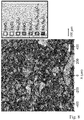
- Fig. 7 the microstructure of the target material produced in this way, determined by means of Raman mapping, is shown.
- areas with MoO 2 phase, areas with Mo 4 O 11 phase and areas with Ta 2 O 5 phase can be seen in accordance with the phase proportions shown above.
- These different phases are embedded in a matrix which is formed by the (Mo 0.93 Ta 0.07 ) 5 O 14 phase.
- a Raman mapping of a target material is shown which has no matrix phase made of the mixed oxide (Mo 0.93 Ta 0.07 ) 5 O 14 .
- the (Mo 0.93 Ta 0.07 ) 5 O 14 phase is present in a proportion of 24.0% by volume .
- the Mo 4 O 11 phase has a proportion of 50.3% by volume
- the MoO 2 phase has a proportion of 12.5% by volume
- the Mo 13 O 52 phase has a proportion of 5.0% by volume
- the Ta 2 O 5 phase has a share of 2.4% by volume
- the MoO 3 phase has a proportion of 5.8% by volume.
- the phases within the target material of the comparative example are significantly more coarse-grained and more unevenly distributed in comparison to the target material according to the invention Fig. 7 .
- MoO 2 powder (Plansee SE; d50 value of approx. 6 ⁇ m) is sieved off in a sieve with a mesh size of 63 ⁇ m, the coarse fraction> 63 ⁇ m not being used any further.
- 52 mol.% Of the MoO 2 powder thus obtained are mixed with 42 mol.% MoO 3 powder (Molymet, in the present case with ad50 value of approx. 3 ⁇ m) and 6 mol% tantalum pentoxide powder (HC Starck, d50 value of approx. 2 ⁇ m; sieved to ⁇ 63 ⁇ m; Ta 2 O 5 ) in a ploughshare mixer (Lödige) for 20 min. mixed so that there is a homogeneous distribution between the powder components.
- the powder mixture obtained is placed in a graphite mold with the dimensions ⁇ 250 mm (ie diameter of 250 mm) and a height of 50 mm and placed in a hot press under vacuum at a pressure of 30 MPa, a temperature of 800 ° C and a holding time of 480 Minutes compacted.
- the compacted component has a relative density of 97.5%.
- the majority of the target material obtained consists of the matrix phase of the mixed oxide (Mo 0.93 Ta 0.07 ) 5 O 14 with a proportion of 80.3% by volume .
- the received Target material has a MoO 2 phase with a proportion of 18.9% by volume, a Mo 4 O 11 phase with a proportion of 0.2% by volume and a Ta 2 O 5 phase with a proportion of 0.6 % By volume.
- MoO 2 powder (Plansee SE; d50 value of approx. 6 ⁇ m) is sieved off in a sieve with a mesh size of 63 ⁇ m, the coarse fraction> 63 ⁇ m not being used any further.
- 45 mol% of the MoO 2 powder obtained in this way are mixed with 51 mol% MoO 3 powder (Molymet, in this case with ad50 value of approx. 3 ⁇ m) and 4 mol% niobium pentoxide powder (HC Starck, d50 value of approx. 2 ⁇ m; sieved to ⁇ 63 ⁇ m; Nb 2 O 5 ) in a ploughshare mixer (Lödige) for 20 min.
- the powder mixture obtained is placed in a graphite mold with the dimensions ⁇ 250 mm (ie diameter of 250 mm) and a height of 50 mm and placed in a hot press under vacuum at a pressure of 30 MPa, a temperature of 800 ° C and a holding time of 360 Minutes compacted.
- the majority of the target material obtained consists of the matrix phase of the mixed oxide (Mo 0.91 Nb 0.09 ) 5 O 14 phase with a proportion of 78.6% by volume.
- the compacted component has a relative density of 98.2%.
- the target material obtained has a MoO 2 phase with a proportion of 18.7% by volume, a Mo 4 O 11 phase with a proportion of 2.6% by volume and an Nb 2 O 5 phase with a proportion of 0 , 1 vol.%.
- MoO 2 powder (Plansee SE; d50 value of approx. 6 ⁇ m) is sieved off in a sieve with a mesh size of 63 ⁇ m, the coarse fraction> 63 ⁇ m not being used any further.
- 39 mol% of the MoO 2 powder obtained in this way are mixed with 52 mol% MoO 3 powder (Molymet, in the present case with ad50 value of approx. 3 ⁇ m) and 8 mol% titanium dioxide powder (rutile; d50 value of ⁇ 1 ⁇ m; TiO 2 ) in a ball mill for 10 min. ground and then in an intensive mixer (Eirich) for 10 min. mixed so that there is a homogeneous distribution between the powder components.
- the powder mixture obtained is in a graphite form with the dimensions 0100mm and a height of 50 mm and in a hot press under vacuum at a pressure of 30 MPa, a temperature of 800 ° C and a holding time of 120 min. condensed.
- the compacted component has a relative density of 91.2%.
- the target material obtained has a matrix phase made of the mixed oxide (Mo 0.97 Ti 0.03 ) 5 O 14 .
- the molybdenum-tantalum-oxide target materials produced according to Example 1 and Example 2 were non-reactively sputtered in comparison with a non-inventive molybdenum-tantalum-oxide target material (reference) under specified process conditions in order to determine the layer properties .
- the molybdenum-tantalum-oxide target material used as reference had the same composition as in Examples 1 and 2, but without a matrix phase consisting of the mixed oxide (Mo 0.93 Ta 0.07 ) 5 O 14 being present.
- a sputtering power of 100 W and a process pressure of the argon of 5.0 ⁇ 10 -3 mbar (22 sccm; sscm: standard cubic centimeters per minute) were used.
- the deposition rate of the sputtering targets used is in Fig. 9 with the left column in Fig. 9 the target material from Example 1 (Ex. 1), the middle column corresponds to the target material from Example 2 (Ex. 2) and the right column corresponds to the target material of the reference.
- the reflectivity of the layers produced was used as a criterion for the assessment.
- glass substrates Cornning Eagle XG, 50 ⁇ 50 ⁇ 0.7 mm 3
- the above-mentioned molybdenum-tantalum oxide target materials produced according to Example 1 and Example 2 were sputtered non-reactively under specified process conditions in comparison to the above-mentioned molybdenum-tantalum oxide target material (reference) not according to the invention.
- the reflection was measured through the glass substrate using a Perkin Elmer Lambda 950 photospectrometer over the indicated wavelength range.
- the layer thickness of the molybdenum-tantalum oxide was varied in a range from 40 to 60 nm.
- the Results from this test series for a molybdenum-tantalum oxide layer thickness of 50 nm are shown in Fig. 10 shown, with the reflectivity in (%) plotted against the wavelength in (nm; nanometers).
- the reflectivity curves from example 1 (example 1; dotted curve) and example 2 (example 2; dashed curve) almost lie on top of one another, except that the reflectivity curve of example 1 is slightly increased in the range of higher wavelengths.
- the curves are clearly below the reflectivity curve of the reference not according to the invention, shown in solid lines.
- the target materials according to the invention have the further advantages explained above.
- the target materials according to the invention due to their electrical conductivity and advantageous phase composition (matrix phase; fine distribution of the second phases), they have a preferred sputtering behavior (uniform sputtering rate while avoiding arcs and particle formation), which has a positive effect on the layer quality (homogeneous layer composition; uniform layer thickness).
- a metallographic section was produced from a representative sample part by means of dry preparation by cutting a sample with an area of approx. 10-15 x 10-15 mm 2 in the dry cutting process (diamond wire saw, Band saw, etc.), cleaned with compressed air, then embedded in a warm and conductive (C-doped) phenolic resin, sanded and polished. Since at least the MoO 3 phase portion is water-soluble, a dry preparation is important. The section obtained in this way was then analyzed using a light microscope.
- Raman spectra are obtained from the backscattered radiation, which is split up by an optical grating (300 lines / mm; spectral resolution: 2.6 cm -1 ) in a wavelength-dispersive manner, and using a CCD detector (1024 x 256 pixel multichannel CCD; spectral range: 200 -1050 nm).
- an optical grating 300 lines / mm; spectral resolution: 2.6 cm -1
- CCD detector 1024 x 256 pixel multichannel CCD; spectral range: 200 -1050 nm.
- the excitation energy density (5 mW / ⁇ m 2 ) is chosen to be low enough to avoid phase changes in the sample. With molybdenum oxides, the penetration depth of the excitation radiation is limited to a few micrometers (in the case of pure MoO 3, for example, to approx. 4 ⁇ m).
- the Raman signal was averaged over 1 s (s: second) acquisition time, resulting in a sufficiently good signal-to-noise ratio.
- Automated evaluation of these Raman spectra (evaluation software Horiba LabSpec 6) created a two-dimensional representation of the surface composition of the sample, from which the domain size, area proportions, etc. of the various phases can be determined quantitatively.
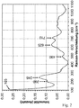
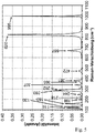
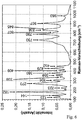
- Figs. 1 to 6 are used reference spectra of (Mo 0.93 Ta 0.07 ) 5 O 14 ( Fig. 1 ), Ta 2 O 5 ( Fig. 2 ), Mon 18 O 52 ( Fig. 3 ), MoO 2 ( Fig. 4 ), MoO 3 ( Fig. 5 ), Mo 4 O 11 ( Fig. 6 ) (in the individual spectra the intensity (number) of the scattered light is plotted against the Raman shift (cm -1 )).
- the analysis and The Raman spectra are assigned with the aid of the "Multivariate Analysis Module" of the above-mentioned evaluation software using the CLS method (classical least square fitting).
- Each measuring point is then assigned a color that corresponds to a metal oxide phase, with only the phase with the highest weighting factor c i being used for the color assignment.
- the size (the amount) of the weighting factor c i determines the brightness of the measuring point. This procedure is justified because the spectrum from one measuring point can usually be clearly assigned to a single metal oxide phase.
- the analysis method described here is very suitable for determining the relative phase proportions of the phases in question.
- the relative density of the target material is determined by means of digital image analysis of light microscopic images of the metallographic section, in which the relative surface area "FA" of the pores is determined. For this purpose, after the samples had been prepared, three bright-field recordings each with a size of 1 x 1mm 2 with 100-fold magnification were taken, with zones of obvious breakouts or other damage patterns such as scratches due to dry preparation being avoided as far as possible.
- the image area to be measured was adjusted (ROI) to exclude the scale bar.
- the result is the relative surface area "FA” of the pores (in percent) and the image colored according to the selected gray level interval (colored means that this pixel was included in the measurement and was therefore counted as a pore).
- the value (1-FA) for the relative density was determined as the arithmetic mean of three such porosity measurements.
Landscapes
- Chemical & Material Sciences (AREA)
- Engineering & Computer Science (AREA)
- Materials Engineering (AREA)
- Chemical Kinetics & Catalysis (AREA)
- Mechanical Engineering (AREA)
- Metallurgy (AREA)
- Organic Chemistry (AREA)
- Plasma & Fusion (AREA)
- Analytical Chemistry (AREA)
- Physics & Mathematics (AREA)
- Physical Vapour Deposition (AREA)
- Compositions Of Oxide Ceramics (AREA)
- Inorganic Compounds Of Heavy Metals (AREA)
Abstract
Description
- Die vorliegende Erfindung betrifft ein Sputteringtarget zur Herstellung molybdänoxidhaltiger Schichten sowie die Verwendung solch eines Sputteringtargets zur Gasphasen-Abscheidung einer molybdänoxidhaltigen Schicht.
- Molybdänoxidhaltige Schichten (insbesondere auf Basis von Molybdänoxid) haben interessante optische Eigenschaften und finden deshalb insbesondere Anwendung bei Schichtstrukturen in optischen bzw. optoelektronischen Applikationen wie beispielsweise elektronischen Displays. Ihre Anwendung erfolgt häufig in Kombination mit bzw. direkt angrenzend zu metallischen Schichten aus z.B. Aluminium (AI), Kupfer (Cu), Titan (Ti), oder (metallischem) Molybdän (Mo), die z.B. als elektrische Leiterbahnen fungieren. Ein Anwendungsbeispiel von Molybdänoxidschichten ist
JP 2013020347 A - Wichtige Eigenschaften wie Lichtabsorptions-, Lichtreflexions-, Lichttransmissionsgrad, Ätzrate, thermische Stabilität sowie Stabilität gegenüber weiteren im Fertigungsprozess eingesetzten Chemikalien (z.B. Fotolack-Entwickler bzw. -Entferner), hängen von der genauen stöchiometrischen Zusammensetzung der abgeschiedenen molybdänoxidhaltigen Schicht sowie den zugefügten Dotierungselementen (z.B. Ta, Nb, etc.) ab. Die Ätzrate ist dabei relevant bei anschließender Strukturierung der abgeschiedenen Schicht mittels Fotolithographie in Verbindung mit einem nasschemischen Ätzprozess. So werden in vielen Anwendungen, wie beispielsweise bei dem oben genannten kapazitiven Berührungssensor, molybdänoxidhaltige Schichten gefordert, in denen das Oxid (Molybdänoxid und/oder ein molybdänhaltiges Mischoxid) in einer substöchiometrischen Zusammensetzung vorliegt, d.h. das Oxid hat unbesetzte Sauerstoff-Valenzen und es liegen in der abgeschiedenen molybdänoxidhaltigen Schicht Sauerstofffehlstellen vor. In solchen substöchiometrischen molybdänoxidhaltigen Schichten (insbesondere auf Basis von Molybdänoxid) können interessante elektro-optische Eigenschaften erzielt werden, wie beispielsweise eine hohe Lichtabsorption (und korrespondierend damit eine niedrige Lichtreflektion) im sichtbaren Wellenlängenbereich, insbesondere bei einer Referenzwellenlänge von 550 nm, und gleichzeitig eine ausreichende elektrische Leitfähigkeit (insbesondere von einem Flächenwiderstand < 20 kΩ/□ bzw. < 20 kΩ/Square). Reine Molybdänoxid-Schichten haben zwar attraktive elektro-optische Eigenschaften, sie weisen jedoch in der Regel in gängigen Nassätzmedien (z.B. PAN-Ätze auf der Basis von Phosphorsäure, Salpetersäure und Essigsäure zum Strukturieren von Aluminium-Metallisierungen, Ätze auf H2O2-Basis zum Strukturieren von Cu) eine zu hohe Ätzrate auf, was zu instabilen Ätzergebnissen führt. Durch die Zugabe von Dotierungselementen in die substöchiometrische molybdänoxidhaltige Schicht (und entsprechend in das Targetmaterial des Sputteringtargets), wie z.B. von Ta und/oder Nb, kann die Ätzrate auf ein akzeptables Niveau abgesenkt werden, ohne dass sich die elektro-optischen Eigenschaften erheblich ändern.
- Derartige molybdänoxidhaltige Schichten (insbesondere auf Basis von Molybdänoxid) werden industriell in einem Beschichtungsprozess mittels Kathodenzerstäubung ("Sputtern") hergestellt. Grundsätzlich ist es zwar möglich, solche molybdänoxidhaltigen Schichten durch reaktives Sputtern eines metallischen Targetmaterials, das z.B. in einer entsprechend eingestellten Argon- und Sauerstoff-Prozessgasatmosphäre reaktiv gesputtert wird, herzustellen. Die Metallatome des Targetmaterials reagieren dabei zu einem hohen Anteil erst während des Beschichtungsprozesses mit dem Sauerstoff aus dem Prozessgas, so dass die Prozessführung durch Hystereseeffekte (diskontinuierliche Änderungen der Schichtabscheiderate, des Entladungsstromes und/oder der Targetspannung aufgrund von Änderungen des Sauerstoffpartialdruckes) und Vergiftung der Targetoberfläche (Engl. target poisoning) erschwert wird. Demgegenüber ist die Abscheidung von einem Sputteringtarget mit oxidischem Targetmaterial unter industriellen Bedingungen vorteilhaft, da der Beschichtungsprozess entweder mit einem reinen Edelgas-Prozessgas (in der Regel Argon) oder mit Edelgas (in der Regel Argon) als Hauptbestandteil, dem geringe Mengen weiterer Gase, wie z.B. Sauerstoff, zugesetzt sind, durchgeführt werden kann. Insbesondere werden beim Einsatz oxidischen Targetmaterials höhere Beschichtungsraten und eine höhere Prozessstabilität unter gleichzeitiger Vereinfachung der Prozessführung ermöglicht. Des Weiteren sind viele bereits installierte Beschichtungsanlagen lediglich für das Abscheiden von metallischen Schichten von einem metallischen Sputteringtarget ausgelegt und erlauben deshalb nicht die Zudosierung von Sauerstoff in das Sputtergas. Die Vielseitigkeit solcher einsetzbaren Sputteranlagen kann durch den Einsatz eines oxidischen Targetmaterials erhöht werden.
- Die
DE 10 2012 112 739 A1 beschreibt ein substöchiometrisches Targetmaterial, bei dem ein Sauerstoffmangel entweder durch eine reduzierte Oxidphase von substöchiometrischem und dadurch elektrisch leitfähigem Oxid oder Oxinitrid auf der Basis von Nb2O5-y, TiO2-y, MoO3-y, WO3-y, V2O5-y (y>0) oder deren Mischungen allein oder durch die reduzierte Oxidphase zusammen mit einer metallischen Beimischung eingestellt wird. In derUS 2001/0020586 A1 ist ein substöchiometrisches Targetmaterial der chemischen Zusammensetzung MOy beschrieben, bei dem M mindestens ein Metall aus der Gruppe Ti, Nb, Ta, Mo, W, Zr und Hf ist. - Losgelöst von den oben genannten Herausforderungen und Rahmenbedingungen bezüglich molybdänoxidhaltiger Schichten und entsprechender Targetmaterialien ist in wissenschaftlichen Veröffentlichungen die Herstellung pulverförmiger, molybdänhaltiger Mischoxidverbindungen im labortechnischen Maßstab (d.h. Produktmengen von wenigen Gramm) mit Haltezeiten bei erhöhten Temperaturen von einer oder mehreren Wochen beschrieben. So beschreiben zum Beispiel Ekström und Nygren (Thommy Ekström and Mats Nygren, Acta Chemica Scandinavica 26 (1972) 1836-1842) die Synthese von (Mo1-xTax)5O14 in einem Homogenitätsbereich von 0,06 ≤ x ≤ 0,08 durch Mischen von Ta2O5-Pulver mit MoO3 und MoO2, Einfüllen der Pulvermischung in Quarzampullen, Evakuieren der Quarzampullen und Aufheizen auf 640 - 750°C für eine Zeitdauer von einer bis mehrere Wochen. In der gleichen Veröffentlichung wird auch die Synthese von (Mo1-xNbx)5O14 in einem Homogenitätsbereich von 0,07 ≤ x ≤ 0,12 beschrieben. Ausgangspulver waren Nb2O5, MoO3 und MoO2, die Synthesebedingungen waren analog wie bei (Mo1-xTax)5O14, allerdings wurde das Mischoxid in einem Temperaturbereich von 600 - 750 °C erhalten. Ekström und Nygren beschreiben in einer weiteren Veröffentlichung (Thommy Ekström and Mats Nygren, Acta Chemica Scandinavica 26 (1972) 1827-1835) auch die Synthese von (Mo1-xVx)5O14, welches aus einer Pulvermischung von V2O5 mit MoO3 und MoO2 analog den bereits beschrieben Mischoxiden hergestellt wurde, wobei ein breiter Homogenitätsbereich von 0,02 ≤ x ≤ 0,11 bei einem Aufheizen auf 640°C bzw. von 0,05 ≤ x ≤ 0,11 bei einem Aufheizen auf 750°C beobachtet wurde. Auch die Synthese von (Mo1-xTix)5O14 mit einem Homogenitätsbereich von 0,03 ≤ x ≤ 0,05 wurde von Ekström bereits beschrieben (Thommy Ekström, Acta Chemica Scandinavica 26 (1972) 1843-1846), wobei die Herstellung aus einer Pulvermischung von TiO2, MoO2 und MoO3 analog den bereits beschriebenen Mischoxiden mit einem Aufheizen auf eine Temperatur von 600 bis 750°C erfolgte. Bei sämtlichen Synthesen wurde das Produkt lediglich in geringen Mengen (Gramm-Maßstab) in loser Pulverform, nicht als solider makroskopischer Festkörper, erhalten.
- Dementsprechend besteht die Aufgabe der vorliegenden Erfindung darin, dotierte molybdänoxidhaltige Sputteringtargets bereitzustellen, bei denen ein stabiler Sputterprozess zur Herstellung qualitativ hochwertiger Schichten einstellbar ist, wobei die Sputteringtargets kostengünstig und prozesssicher in industriellem Maßstab herstellbar sein sollen.
- Die Aufgabe wird gelöst durch ein Sputteringtarget gemäß Anspruch 1 sowie durch eine Verwendung eines Sputteringtargets gemäß Anspruch 15. Vorteilhafte Weiterbildungen der Erfindung sind in den abhängigen Ansprüchen angegeben.
- Gemäß der vorliegenden Erfindung wird ein Sputteringtarget mit einem elektrisch leitfähigen, oxidischen Targetmaterial bereitgestellt. Das Targetmaterial enthält dabei mindestens ein Metalloxid
- von Molybdän (Mo) als metallischem Hauptbestandteil und
- von mindestens einem Dotierungselement M aus der Gruppe Tantal (Ta), Niob (Nb), Vanadium (V) und Titan (Ti).
- Das Targetmaterial weist dabei - bezogen auf ein Schliffbild desselben und gemessen mit einem Raman-Mikroskop (mittels Raman-Spektroskopie) - eine Matrixphase aus einem Mischoxid (Mo1-xMx)5O14 mit 0,01 ≤ x ≤ 0,13 auf, wobei M in diesem Mischoxid eines oder mehrere Elemente der Gruppe Tantal (Ta), Niob (Nb), Vanadium (V) und Titan (Ti) ist.
- Der vorliegenden Erfindung liegt dabei die Erkenntnis zugrunde, dass es im Hinblick auf die Prozessstabilität des Sputterprozesses vorteilhaft ist, wenn der Sauerstoffgehalt des Targetmaterials identisch oder im Wesentlichen identisch zu demjenigen der herzustellenden Schicht ist. Vorzugsweise weichen der Sauerstoffgehalt (Gew.%) des Targetmaterials und der Sauerstoffgehalt (Gew.%) der herzustellenden Schicht um maximal ± 2 Gew.% voneinander ab. Eine Zuführung von Sauerstoff über das Prozessgas ist damit nicht oder nur zu einem geringen Anteil erforderlich, wodurch Hystereseeffekte unterdrückt und die Prozessführung vereinfacht werden.
- Ferner ist zu berücksichtigen, dass grundsätzlich eine Vielzahl von Phasenzusammensetzungen eines dotierten, molybdänoxidhaltigen Targetmaterials möglich sind. Zum einen kann Molybdän in unterschiedlichen Oxidationsstufen vorliegen, insbesondere in Form von MoO2, von MoO3, sowie in Form einer Mehrzahl von substöchiometrischen Oxiden MoOy, wie z.B. Mo4O11 (y=2,75), Mo17O47 (y=2,76), Mo5O14 (y=2,8), Mo8O23 (y=2,875), Mo9O26 (y=2,89) und Mo18O52 (y=2,89), wobei Mo9O26 die Hochtemperaturmodifikation und Mo18O52 die Tieftemperaturmodifikation bildet. Erfindungsgemäß ist vorgesehen, dass das mindestens eine Dotierungselement M in dem Targetmaterial enthalten ist. Bezüglich der möglichen Phasenzusammensetzungen des Targetmaterials kommen hierdurch weitere Freiheitsgrade hinzu, denn das mindestens Dotierungselement M kann grundsätzlich elementar in dem Target (d.h. in metallischer Form, z.B. als Ta, Nb, V, Ti) vorliegen, es kann als Oxid vorliegen (z.B. Ta2O5, V2O5, Nb2O5, TiO2), es kann als substöchiometrisches Oxid vorliegen sowie ferner kann es ein Mischoxid mit einem oder mehreren der oben genannten Molybdänoxide und/oder mit einem oder mehreren Oxiden des mindestens eines weiteren Dotierungselements M bilden. Im Hinblick auf die Vielzahl an möglichen Phasenzusammensetzungen liegt der vorliegenden Erfindung die Erkenntnis zugrunde, dass unterschiedliche Phasen des Targetmaterials, insbesondere wenn sie teilweise isolierend oder dielektrisch sind, zu Partikelbildung durch Ausbildung von Lichtbögen (Arcs) beim Sputtern führen können. In Folge dessen kann es zu Schichtfehlern oder Beschädigung des Sputteringtargets kommen. Weiterhin ist die Festigkeit von oxidischen Targets eher gering, vor allem wenn die Mikrostruktur mehrere unterschiedliche, ungleichmäßig verteilte, grobe und/oder poröse Phasen aufweist. Besonders kritisch im Hinblick auf die Festigkeit ist es, wenn Phasen unterschiedliche Dichten oder CTE's (CTE: coefficient of thermal expansion; thermischer Ausdehnungskoeffizient) haben und/oder aneinander angrenzende Phasen aufgrund von z.B. Diffusionsporen, unterschiedlichen Gittertypen, etc., nicht ausreichend fest miteinander verbunden sind. Verschiedene Phasen weisen teilweise auch unterschiedliche Sputterraten auf, wodurch gerade bei mehreren, ungleichmäßig verteilten, groben und porösen Phasen des Targetmaterials die Schichthomogenität und die Schichtstöchiometrie der hergestellten Schichten unzureichend sein können. Teilweise sind die Phasen (z.B. MoO3) bedingt wasserlöslich, wodurch es beim Herstellprozess (z.B. mechanische Bearbeitung, Reinigung) zu Änderungen der Stöchiometrie im Oberflächenbereich und/oder zur Einlagerung von Restfeuchtigkeit kommen kann, was sich wiederum negativ auf den Sputterprozess sowie die hergestellte Schicht auswirken kann (z.B. Beeinträchtigung des Vakuums, Einlagerung von H2O in die Schicht).
- Demgegenüber wurde festgestellt, dass die erfindungsgemäß vorgesehene (Mo1-xMx)5O14-Mischoxidphase mit 0,01 ≤ x ≤ 0,13 in dem Targetmaterial besonders vorteilhaft ist, da sie elektrisch leitfähig ist, keine Wasserlöslichkeit aufweist und unter Umgebungsbedingungen stabil ist. Weiterhin ist dadurch auch das Dotierungselement M (zumindest anteilig) in dieser Matrixphase und damit in einer elektrisch leitfähigen Phase gebunden und gleichmäßig über das Targetmaterial verteilt. Indem diese Mischoxidphase erfindungsgemäß die Matrixphase bildet, in der gegebenenfalls vorhandene Zweitphasen (vorzugsweise feinverteilt) eingelagert sein können, nimmt sie einen erheblichen und durch das Sputteringtarget hindurchgehenden Anteil des Targetmaterials ein, wodurch das gesamte Targetmaterial mit diesen vorteilhaften Eigenschaften geprägt wird. Zum Beispiel ist damit eine elektrische Leitfähigkeit durch das gesamte Targetmaterial hindurch gegeben und ein Kontakt mit Wasser ist relativ unkritisch, da die Matrix hierdurch nicht angegriffen wird. Wie oberhalb erläutert wird, sind diese Eigenschaften vorteilhaft im Hinblick auf eine gleichmäßige Sputterrate, auf die Vermeidung von Lichtbögen (Arcs) und Partikelbildung, auf eine homogene Schichtzusammensetzung und eine gleichmäßige Schichtdicke, auf eine stabile Prozessführung während des Sputterprozesses sowie im Hinblick auf eine einfache Herstellung, Aufbewahrung und Handhabung des Sputteringtargets. Weiterhin vorteilhaft ist, dass das erfindungsgemäße Sputteringtarget in industriellem Maßstab als kompaktes Bauteil (kompaktes Targetmaterial von z.B. mindestens 1 kg pro Targetsegment) mit hoher relativer Dichte und hoher Phasenreinheit innerhalb kurzer Prozesszeiten (z.B. Haltezeiten typischerweise < 12 Stunden) herstellbar ist, wie nachstehend noch im Detail beschrieben wird.
- Das "Sputtern", auch Kathodenzerstäubung genannt, ist ein physikalischer Vorgang, bei dem Atome oder Moleküle aus einem Festkörper (Targetmaterial) durch Beschuss mit energiereichen Ionen (z.B. Edelgasionen des Prozessgases) herausgelöst werden und in die Gasphase übergehen. Zur Herstellung dünner Schichten wird das zerstäubte Targetmaterial auf einem Substrat abgeschieden und bildet dort eine feste Schicht aus. Dieser zum Teil auch als Sputterdeposition bezeichnete Beschichtungsvorgang zählt zu den PVD-Verfahren (PVD: physical vapour deposition; physikalische Gasphasenabscheidung) und wird nachfolgend ebenfalls als "Sputtern" bezeichnet. Als Targetmaterial wird dasjenige als Festkörper vorliegende Material eines Sputteringtargets bezeichnet, das für die Zerstäubung während des Sputterprozesses und für die Schichtbildung (ggf. gemeinsam mit weiteren Materialien aus dem Prozessgas und/oder von weiteren Sputteringtargets) vorgesehen ist. Das Sputteringtarget kann ausschließlich durch das Targetmaterial gebildet werden oder darüber hinaus auch noch weitere, mit dem Targetmaterial direkt oder mittelbar (d.h. über mindestens ein weiteres Bauteil) verbundene Bauteile aufweisen, wie z.B. Rückplatte(n), Trägerrohr(e), Anschlussstück(e), Einsätz(e). Das Sputteringtarget (und entsprechend das Targetmaterial) kann dabei in unterschiedlichen Geometrien bereitgestellt werden, insbesondere als planares Sputteringtarget mit unterschiedlichen Grundformen, wie z.B. quadratisch, rechteckig, rund, etc., oder auch als rohrförmiges Sputteringtarget. Das Targetmaterial bildet insbesondere einen makroskopischen Festkörper mit einer Ausdehnung entlang mindestens einer Raumrichtung von mindestens 0,03 m (Meter).
- Unter einem "oxidischen" Targetmaterial wird verstanden, dass die in dem Targetmaterial enthaltenen Metalle im Wesentlichen vollständig als Oxide vorliegen. Insbesondere ist in dem Targetmaterial der Anteil an metallischen Phasen bezogen auf ein Schliffbild desselben < 1 Vol.%. Insbesondere ist der Anteil an metallischen Phasen in dem Targetmaterial unterhalb der Nachweisgrenze mittels der hier angewandten und nachstehend noch näher beschriebenen Raman-Messungen. Als "elektrisch leitfähig" wird das Targetmaterial dann bezeichnet, wenn es eine elektrische Leitfähigkeit von mindestens 80 S/m aufweist, gemessen über einen Widerstands-Messstand (Ulvac ZEM3) mit der 4-Punkt-Messmethode. Als "Phase" des Targetmaterials wird ein räumlicher Bereich desselben verstanden, innerhalb dessen eine einheitliche chemische Zusammensetzung und eine einheitliche Kristallstruktur gegeben ist, wobei die Ausrichtung der einzelnen Kristallkörner innerhalb einer Phase unterschiedlich sein kann. Als "Mischoxid" wird ein Oxid mit einer Kristallstruktur verstanden, bei dem sich das Kristallgitter aus Sauerstoffionen sowie Kationen mehrerer Elemente (vorliegend insbesondere von Mo und mindestens ein Dotierungselement M) zusammensetzt. Unter einer "Matrixphase" wird vorliegend verstanden, dass diese das Targetmaterial in einem zusammenhängenden, perkolierenden Netzwerk durchzieht, in das ggf. vorhandene weitere Phasen ("Zweitphasen") als inselförmige Bereiche eingebettet sind (zu beobachten am Schliffbild mit einem Raman-Mikroskop mittels Raman-Spektroskopie).
- Die Bestimmung der verschiedenen Phasen und deren Volumenanteile sowie auch der Dichte des Targetmaterials erfolgen anhand eines repräsentativen Querschnitts einer Probe, wobei - da ein isotropes Gefüge angenommen werden kann - die Volumenangaben aus an der Schnittfläche gemessenen Flächenanteilen abgeleitet werden (d.h. die Volumenanteile entsprechen den gemessenen Flächenanteilen). Mittels Trockenpräparation wird hierzu ein metallographischer Schliff der Probe hergestellt, wobei zur ortsaufgelösten Bestimmung der verschiedenen Metalloxid-Phasen die Raman-Spektroskopie unter Einsatz eines Raman-Mikroskops angewendet wird. Wie nachstehend noch im Detail beschrieben ist, wird bei der Raman-Spektroskopie die zu analysierende Probenoberfläche des Targetmaterials punktweise mit einem Laserstrahl abgerastert und für jeden Messpunkt ein vollständiges Raman-Spektrum erstellt ("Raman-Mapping"). Durch Vergleich des erhaltenen Raman-Spektrums für jeden Messpunkt mit Referenzspektren von verschiedenen, in Frage kommenden Metalloxiden, wird jedem Messpunkt eine entsprechende Phase zugeordnet und so eine zweidimensionale Darstellung der Phasenzusammensetzung der Probe erstellt, aus der sich dann die Flächenanteile (bzw. die Volumenanteile) der verschiedenen Phasen berechnen lassen. Die (Mo1-xMx)5O14 Matrixphase kann mittels Raman-Spektroskopie eindeutig identifiziert werden. Ein Referenz-Ramanspektrum einer (Mo0,93Ta0,07)5O14-Phase ist in
Figur 1 gezeigt. Die Pulverdiffraktogrammdaten sind unter der PDF Nr. 01-070-0952 vom Internationalen Zentrum für Beugungsdaten (International Centre for Diffraction Data; ICDD) erhältlich. Die Volumenangaben (bzw. die hierzu identischen Flächenangaben) der verschiedenen Metalloxid-Phasen sind normiert und Relativangaben bezüglich des Gesamtvolumens (bzw. der Gesamtfläche), das von den materiellen Teilchen (Körnern) des Targetmaterials eingenommen wird. Das von den Poren des Targetmaterials eingenommene Volumen (bzw. die hierzu identische Fläche) ist von diesem Gesamtvolumen (bzw. dieser Gesamtfläche) ausgeklammert. Die Volumenangaben (bzw. die hierzu identischen Flächenangaben) der einzelnen Metalloxid-Phasen addieren sich daher allein ohne das Porenvolumen auf 100%. - Gemäß der vorliegenden Erfindung kann das Targetmaterial aus einem Metalloxid oder auch aus mehreren Metalloxiden unterschiedlicher chemischer Zusammensetzung (die dann unterschiedliche Phasen bilden), gebildet werden. Dabei kann das jeweilige Metalloxid ein stöchiometrisches oder ein substöchiometrisches Metalloxid von genau einem Metall oder alternativ von mehreren Metallen (d.h. in letzterem Fall ein Mischoxid) sein. In dem Targetmaterial bildet Mo erfindungsgemäß bzgl. der enthaltenen Metalle (die als Kationen vorliegen), den Hauptbestandteil, d.h. der Mo-Anteil (Mo; in at.%) relativ zu der Summe aller enthaltenen Metalle (Me; in at.%) einschließlich des Mo-Anteils (Mo; in at.%), d.h. Mo/(Me+Mo) beträgt mindestens 50%. Insbesondere beträgt er mindestens 80%, noch bevorzugter mindestens 84%. Grundsätzlich können neben Mo und dem mindestens einen Dotierungselement M auch noch weitere Metalle in dem Targetmaterial enthalten sein. Vorzugsweise werden jedoch die weiteren, in dem Targetmaterial neben Mo enthaltenen Metalle - abgesehen von ggf. vorhandenen Verunreinigungen - ausschließlich durch das mindestens eine Dotierungselement M gebildet. Grundsätzlich können in dem Targetmaterial zwei oder mehrere Dotierungselemente M aus der Gruppe Ta, Nb, V und Ti enthalten sein. Insbesondere ist in dem Targetmaterial aber nur genau ein Dotierungselement M aus dieser Gruppe enthalten. Bevorzugt ist dieses genau eine Dotierungselement M Ta oder alternativ Nb. Durch die Zugabe von Ta und/oder Nb als Dotierungselement kann die Naßätzrate in einem gängigen Aluminium-Ätzmittel (Mischung aus Phosphorsäure, Salpetersäure, Essigsäure und Wasser) auf ein akzeptables Maß abgesenkt werden. Auch die Naßätzrate in Kupfer-Ätzmitteln auf Basis von Wasserstoffperoxid kann durch Zugabe von Ta oder Nb beeinflusst werden. Ta bzw. Ta-Oxid-Pulver ist ein Ausgangsprodukt, das in großen Mengen verfügbar ist, jedoch starken Preisschwankungen unterliegt. Nb bzw. Nb-Oxid-Pulver ist in der Regel zu einem günstigeren Preis verfügbar.
- Wie erwähnt, können in dem Targetmaterial herstellungsbedingte "Verunreinigungen" (Metalle wie auch Nichtmetalle) enthalten sein, wie z.B. Wolfram (W), Natrium (Na), Kalium (K), Antimon (Sb), Vanadium (V), Chrom (Cr), Eisen (Fe), Kohlenstoff (C) und Stickstoff (N). Der Gesamtgehalt solcher Verunreinigungen ist typischerweise < 1.000 µg/g.
- Grundsätzlich können gemäß der vorliegenden Erfindung in dem Mischoxid (Mo1-xMx)5O14 zwei oder mehrere Dotierungselemente M aus der Gruppe Ta, Nb, V und Ti enthalten sein. Insbesondere ist in dem Mischoxid (Mo1-xMx)5O14 aber nur genau ein Dotierungselement M aus dieser Gruppe enthalten. Weiterhin ist grundsätzlich gemäß der vorliegenden Erfindung möglich, dass auch mehrere unterschiedliche Mischoxide (Mo1-xMx)5O14, jeweils mit M als eines oder mehrere Elemente aus der Gruppe Ta, Nb, V und Ti, in dem Targetmaterial enthalten sind, wobei dann genau eines dieser Mischoxide die genannte Matrixphase bildet. Insbesondere ist aber nur genau ein solches Mischoxid (Mo1-xMx)5O14 enthalten. Insbesondere gilt für den Bereich x innerhalb des Mischoxids (Mo1-xMx)5O14 der Matrixphase 0,02 ≤ x ≤ 0,12.
- Gemäß einer Weiterbildung wird das Targetmaterial durch mindestens ein Metalloxid
- von Molybdän (Mo) als metallischem Hauptbestandteil und
- von mindestens einem Dotierungselement M aus der Gruppe Tantal (Ta), Niob (Nb), Vanadium (V) und Titan (Ti)
- Gemäß einer Weiterbildung weist in dem Targetmaterial die Matrixphase aus dem Mischoxid (Mo1-xMx)5O14 bezogen auf ein Schliffbild des Targetmaterials - gemessen mit einem Raman-Mikroskop (mittels Raman-Spektroskopie) - einen Anteil von ≥ 60 Vol.% auf, d.h. er liegt in dem Bereich von 60-100 Vol.%. Insbesondere beträgt der Anteil ≥ 75 Vol.%, d.h. er liegt in dem Bereich von 75-100 Vol.%, noch bevorzugter beträgt der Anteil ≥ 90 Vol.%, d.h. er liegt in dem Bereich von 90-100 Vol.%. Je höher der Anteil der Mischoxidphase ist, desto stärker wird das Targetmaterial durch die oberhalb erläuterten, vorteilhaften Eigenschaften dieser Matrixphase geprägt. Ein sehr hoher Anteil wird nur dann erzielt, wenn die Zusammensetzung des Targetmaterials dem Verhältnis der betreffenden Elemente in dem Mischoxid (Mo1-xMx)5O14 angenähert ist. Gemäß einer Weiterbildung beträgt der Anteil 100 Vol.% (d.h. es sind keine Zweitphasen nachweisbar). Zur Erreichung von 100 Vol.% muss die Zusammensetzung des Targetmaterials weitgehend dem Verhältnis der Elemente in dem Mischoxid entsprechen. Bzgl. der Bestimmung des Anteils in Vol.% wird auf die voranstehende allgemeine Beschreibung sowie auf die nachstehende detaillierte Beschreibung bzgl. der Probenpräparation und der Raman-Spektroskopie Bezug genommen.
- Gemäß einer Weiterbildung sind in dem Targetmaterial
- a. MoO2 und/oder Mo4O11 sowie
- b. optional eine oder mehrere Verbindung(en) aus der Gruppe:
- MoO3,
- weitere substöchiometrische Molybdänoxide aus der Gruppe Mo17O47, Mo5O14, Mo3O23, Mo9O26 und Mo13O52,
- stöchiometrische (z.B. Ta2O5) und/oder substöchiometrische (z.B. Ta2O5-l; 0<l<1) Ta-Oxid(e),
- stöchiometrische (z.B. Nb2O5) und/oder substöchiometrische (z.B. Nb2O5-m; 0<m<1) Nb-Oxid(e),
- stöchiometrische (z.B. V2O5) und/oder substöchiometrische (z.B. V2O5-n; 0<n<1) V-Oxid(e), und
- stöchiometrische (z.B. TiO2) und/oder substöchiometrische (z.B. TiO2-o; 0<o<1) Ti-Oxid(e),
- Gemäß einer Weiterbildung liegt in dem Targetmaterial bezogen auf ein Schliffbild desselben - gemessen mit einem Raman-Mikroskop (mittels Raman-Spektroskopie) - der Anteil der Zweitphase MoO3 im Bereich von 0 - 2 Vol.%, d.h. der Anteil ist ≤ 2 Vol.%. Der Anteil der Zweitphase MoO3 sollte möglichst niedrig gehalten werden, da MoO3 elektrisch isolierend ist (elektrische Leitfähigkeit kleiner als 1 x 10⁻⁵ S/m), was zu Partikelbildung beim Beschichtungsprozess führen kann. Zudem ist MoO3 wasserlöslich, was nachteilig bei der mechanischen Bearbeitung sowie der Lagerung des Targets ist. Vorzugsweise ist eine Zweitphase MoO3 in dem Targetmaterial mittels Raman- Spektroskopie überhaupt nicht nachweisbar (d.h. gemessener Anteil von 0 Vol.%), bzw. wird - wenn sie nicht ganz vermeidbar ist - auf einen Anteil im Bereich von 0,1 - 1,0 Vol.% gehalten.
- Gemäß einer Weiterbildung liegt in dem Targetmaterial der Sauerstoff-Gehalt in Gew.% im Bereich von 26 bis 32 Gew.%. Der Sauerstoff-Gehalt in der abgeschiedenen Schicht beeinflusst die optische Reflexion, so dass vorzugsweise in dem Targetmaterial ein weitgehend entsprechender Sauerstoff-Gehalt, der typischerweise in dem oben genannten Bereich liegt, eingestellt wird. Weiterhin wird innerhalb dieses Bereiches eine ausreichende elektrische Leitfähigkeit erzielt, so dass ein DC (direct current; Gleichstrom) Sputterprozess ermöglicht wird (während elektrisch isolierende Targets mit einem RF (RF: radio frequency; d.h. Hochfrequenz) Sputterprozess (d.h. Wechselstrom) gesputtert werden müssen, was mit erhöhten Kosten (insbesondere bzgl. der Ausgestaltung der Sputteranlage) verbunden ist. Der Sauerstoff-Gehalt kann dabei - wie nachstehend noch ausführlicher beschrieben wird - im Rahmen der Herstellung durch Einwaage entsprechender oxidhaltiger Pulver eingestellt werden, so dass der eingewogene Sauerstoff-Anteil (im Verhältnis zu dem eingewogenen MetallAnteil) dem gewünschten Sauerstoff-Gehalt des Targetmaterials entspricht. Gleichzeitig ist der genannte Sauerstoff-Gehalt günstig für das Sinterverhalten und die Ausbildung des Mischoxids (Mo1-xMx)5O14 im Rahmen der Herstellung. Die Betrachtung lediglich des Gesamt-Sauerstoff-Gehalts in dem Targetmaterial ist zielführend, da sich die exakte Besetzung der verschiedenen Gitterplätze in den Metalloxidphasen ggf. auch temperaturabhängig ändern kann. Der Gesamt-Sauerstoff-Gehalt im Targetmaterial wird vorliegend mittels Trägergasheißextraktion (Nachweis des Sauerstoffes als CO bzw. CO2 mittels Infrarotmesszelle, z.B. mit einem Gerät LECO RO300 oder LECO 836) ermittelt.
- Gemäß einer Weiterbildung liegt in dem Targetmaterial der Anteil des (mindestens einen) Dotierungselements M in at.% relativ zu dem Gesamtgehalt an Mo und dem Dotierungselement M in at.% in Summe, d.h. M/(Mo+M), in dem Bereich von 0,02 - 0,15. Ein Mindestgehalt des (mindestens einen) Dotierungselements M ist erforderlich, damit sich in dem Targetmaterial das Mischoxid (Mo1-xMx)5O14 als Matrixphase ausbilden kann. Ein gewisser Spielraum besteht dabei, da der Anteil x des Dotierungselements M innerhalb der Matrixphase (Mo1-xMx)5O14 bis zu einem gewissen Grad variieren und damit auch leicht reduziert sein kann. Weiterhin ist ein Mindestgehalt des Dotierungselements M erforderlich, damit die gewünschten Eigenschaften der hergestellten Schicht (insbesondere bzgl. Nassätzverhalten) vorliegen. Umgekehrt ist ein zu hoher Gehalt des Dotierungselements M nachteilig, da das Dotierungselement M dann nicht mehr in der Matrixphase aufgenommen werden kann und folglich zu einem erhöhten Anteil des Oxids des Dotierungselements (z.B. Ta2O5, Nb2O5, V2O5, TiO2) führt, in Form einer Zweitphase. Weiterhin nimmt zum Teil die Reflexion der hergestellten Schichten bei zunehmendem Gehalt des Dotierungselements M (z.B. bei Ta) wieder zu und auch die Ätzrate entspricht nicht mehr dem gewünschten Bereich. Vor diesem Hintergrund ist der Bereich von 0,05 - 0,12 für das Verhältnis M/(Mo+M) besonders bevorzugt. Das gewünschte Verhältnis M/(Mo+M) kann im Rahmen der Herstellung durch Einwaage entsprechender Pulver eingestellt werden, da dieses bei der nachstehend beschriebenen Herstellungsroute weitgehend unverändert bleibt. Am Targetmaterial selbst können die Anteile der enthaltenen Metalle sowie das Verhältnis M/(Mo+M) mittels chemischer Analyse, insbesondere mittels ICP-MS (Inductively Coupled Plasma Mass Spectroscopy; Massenspektrometrie mit induktiv gekoppeltem Plasma) oder mit ICP-OES (Inductively Coupled Plasma Optical Emission Spectrometry; Optische Emissionsspektrometrie mit induktiv gekoppeltem Plasma), bestimmt werden.
- Gemäß einer Weiterbildung wird in dem Targetmaterial das Dotierungselement M durch Ta gebildet und die Matrixphase aus dem Mischoxid wird durch (Mo1-xTax)5O14 mit 0,06 ≤ x ≤ 0,08 gebildet. Typischerweise nimmt der Ta-Anteil x in der Matrixphase (Mo1-xTax)5O14 den Wert 0,07 ein. Je nach Verfügbarkeit von Ta zur Bildung der Matrixphase während der Herstellung (d.h. insbesondere je nach Zusammensetzung und Mengenverhältnis der Ausgangspulver) liegt x in der Regel innerhalb des Bereichs 0,06 ≤ x ≤ 0,08, wobei die Matrixphase in diesem Bereich stabil ausgebildet wird. Wie oberhalb erwähnt, ist Ta hinsichtlich der Beeinflussung der Nassätzrate und der Verfügbarkeit besonders bevorzugt. Auch die Matrixphase (Mo1-xTax)5O14 hat sich in der Praxis als besonders vorteilhaft herausgestellt.
- Vorzugsweise wird ein möglichst hoher Anteil des zugegebenen Dotierungselements M (hier: Ta) in die Matrixphase aus dem Mischoxid (Mo1-xMx)5O14 eingebaut und vorzugsweise liegt das Dotierungselement M (hier: Ta) - sofern es nicht vollständig eingebaut wird - als Metalloxid (z.B. Mischoxid, Ta2O5) und nicht als metallisches Element vor. Ta als metallische Phase würde zu deutlich abweichenden Eigenschaften führen. Auch der Anteil von Ta2O5 ist bevorzugt relativ niedrig, da Ta2O5 dielektrisch ist und damit die Ursache für Partikel und Schichtfehler beim Sputtern sein kann. Ferner wäre Ta2O5 als dünne Teilschicht in der hergestellten Schicht optisch transparent und würde damit die optischen Eigenschaften der Schicht verschlechtern. Dementsprechend liegt Ta (vorzugsweise als einziges enthaltenes Dotierungselement M) in dem Targetmaterial gemäß einer Weiterbildung vollständig als Metalloxid (z.B. Mischoxid, Ta2O5) vor (d.h. nicht als metallisches Element), wobei in dem Targetmaterial bezogen auf ein Schliffbild desselben - gemessen mit einem Raman-Mikroskop (mittels Raman-Spektroskopie) - der Anteil der Phase Ta2O5 ≤ 3 Vol.% (d.h. Anteil von 0-3 Vol.%), vorzugsweise ≤ 1 Vol.% (d.h. Anteil von 0-1 Vol.%), ist. Dies gilt insbesondere für einen Anteil des Dotierungselements Ta in at.% relativ zu dem Gesamtgehalt an Mo und Ta in at.%, d.h. M/(Mo+M), in dem Bereich von 0,02 - 0,15, vorzugsweise im Bereich von 0,05 - 0,12.
- Gemäß einer Weiterbildung wird in dem Targetmaterial das Dotierungselement M durch Nb gebildet und die Matrixphase aus dem Mischoxid wird durch (Mo1-xNbx)5O14 mit 0,07 ≤ x ≤ 0,12 gebildet. Je nach Verfügbarkeit von Nb zur Bildung der Matrixphase während der Herstellung (d.h. insbesondere je nach Zusammensetzung und Mengenverhältnis der Ausgangspulver) liegt x in der Regel innerhalb des Bereichs von 0,07 ≤ x ≤ 0,12, wobei die Matrixphase in diesem Bereich stabil ausgebildet wird. Wie oberhalb erwähnt, ist Nb hinsichtlich der Beeinflussung der Nassätzrate und der preisgünstigen Verfügbarkeit vorteilhaft, auch weil sich die Matrixphase über einen breiteren Bereich von 0,07 ≤ x ≤ 0,12 stabil ausbildet.
- Entsprechend wie oberhalb bzgl. Ta erläutert, wird vorzugsweise ein möglichst hoher Anteil des zugegebenen Dotierungselements M (hier: Nb) in die Matrixphase aus dem Mischoxid (Mo1-xMx)5O14 eingebaut und vorzugsweise liegt das Dotierungselement M (hier: Nb) - sofern es nicht vollständig eingebaut wird - als Metalloxid (z.B. Mischoxid, Nb2O5) und nicht als metallisches Element vor. Dementsprechend liegt Nb (vorzugsweise als einziges enthaltenes Dotierungselement M) in dem Targetmaterial gemäß einer Weiterbildung vollständig als Metalloxid (z.B. Mischoxid, Nb2O5) vor (d.h. nicht als metallisches Element), wobei in dem Targetmaterial bezogen auf ein Schliffbild desselben - gemessen mit einem Raman-Mikroskop (mittels Raman-Spektroskopie) - der Anteil der Phase Nb2O5 ≤ 3 Vol.% (d.h. Anteil von 0-3 Vol.%), vorzugsweise ≤ 1 Vol.% (d.h. Anteil von 0-1 Vol.%), ist. Dies gilt insbesondere für einen Anteil des Dotierungselements Nb in at.% relativ zu dem Gesamtgehalt an Mo und Nb in at.%, d.h. M/(Mo+M), in dem Bereich von 0,02 - 0,15, vorzugsweise im Bereich von 0,05 - 0,12.
- Gemäß einer Weiterbildung weist das Targetmaterial eine relative Dichte von ≥ 95% (d.h. in einem Bereich von 95 - 99,9%), insbesondere von ≥ 97% (d.h. in einem Bereich von 97 - 99,9%), vorzugsweise von ≥ 98% (d.h. in einem Bereich von 98 - 99,9%) auf. Ein kompaktes Targetmaterial mit einer hohen relativen Dichte ist für die Qualität der abgeschiedenen Schichten wichtig, da weniger dichte Targetmaterialien beim Sputtern zu Blitzentladungen ("Arcs") und Partikelbildung führen können. Die Bestimmung der relativen Dichte erfolgt mittels digitaler Bildanalyse anhand von lichtmikroskopischen Bildaufnahmen des metallographischen Schliffs des Targetmaterials, bei dem der relative Flächenanteil "FA" der Poren (FA: Flächenanteil der Poren relativ zur untersuchten Gesamtfläche) ausgewertet wird. Die relative Dichte entspricht dann dem Wert (1-FA), wobei sie als arithmetisches Mittel aus drei derartigen Porositätsmessungen berechnet wird. Die Vorgehensweise ist nachstehend im Detail beschrieben.
- Gemäß einer Weiterbildung weit das Targetmaterial eine elektrische Leitfähigkeit von ≥ 100 S/m bei 25°C auf. Hierdurch wird ein DC Sputtern ermöglicht und auch in der hergestellten Schicht wird eine ausreichende elektrische Leitfähigkeit erzielt. Die elektrische Leitfähigkeit wird dabei mit der 4-Punkt-Messmethode über einen Widerstands-Messstand (z.B. Ulvac ZEM3) gemessen.
- Gemäß einer Weiterbildung liegt das Targetmaterial als ein pulvermetallurgisch hergestellter (makroskopischer) Festkörper vor. Die pulvermetallurgische Herstellungsroute ermöglicht eine kostengünstige Herstellung des Targetmaterials in industriellem Maßstab als kompaktes Bauteil (kompaktes Targetmaterial von z.B. mindestens 1 kg pro Targetsegment) mit hoher relativer Dichte und hoher Phasenreinheit innerhalb kurzer Prozesszeiten (z.B. Haltezeiten typischerweise < 12 Stunden). Unter einer pulvermetallurgischen Herstellung wird dabei verstanden, dass entsprechende Ausgangspulver (die im Falle mehrerer Pulver vorher entsprechend gemischt werden) durch Anwendung von Druck und/oder Temperatur verdichtet werden. Die pulvermetallurgische Herstellung führt dabei zu einer charakteristischen Mikrostruktur des Targetmaterials, insbesondere zu einem mehrphasigen und feinkörnigen Gefüge. Die pulvermetallurgische Herstellung ist für einen Fachmann ohne weiteres an dem Targetmaterial anhand eines Schliffbildes im Lichtmikroskop, im Rasterelektronenmikroskop (REM) oder über Raman-Mikroskop erkennbar.
- Als Ausgangspulver wird vorzugsweise eine Pulvermischung aus MoO2, MoO3, gegebenenfalls enthaltend geringe Anteile an substöchiometrischen Molybdänoxiden wie insbesondere Mo4O11, sowie aus einem oder mehreren Oxiden des Dotierungselements M (Ta2O5, V2O5, Nb2O5, TiO2) gebildet. Die Anteile der verschiedenen Pulver werden so eingewogen, dass das gewünschte Mengenverhältnis der Elemente Mo, M und O eingestellt wird. MoO2 und MoO3 sind leicht zugängliche, günstige und unter Umgebungsbedingungen thermodynamisch stabile, einfach zu handhabende Rohstoffe. Substöchiometrische Oxide können durch Reduktion von MoO3-Pulver in einer entsprechenden Atmosphäre wie H2 hergestellt werden.
- Um die Ausbildung der gewünschten Matrixphase aus dem Mischoxid (Mo1-xMx)5O14 während des nachfolgenden Verdichtungsschritts mit dem gewünschten hohen Anteil zu erzielen, ist zum einen auf ein entsprechendes, nahe an dem Mischoxid liegendes Mengenverhältnis der eingewogenen Pulver zu achten. Ferner ist wesentlich, dass die eingesetzten Pulver sehr feinkörnig sind (mit d50-Werten typischerweise < 10 µm) und vor dem Schritt des Verdichtens sehr gut durchmischt werden. Wie auch anhand der Herstellungsbeispiele erläutert wird, werden bei dem MoO2-Pulver und dem Pulver aus dem Oxid des Dotierungselements M (sowie ggf. auch bei den substöchiometrischen Molybdänoxiden) jeweils der Grobanteil > 63 µm durch einen entsprechenden Siebschritt (z.B. Sieb mit einer Maschenweite von 63 µm) abgesiebt. Auch bei dem MoO3-Pulver wird ein besonders feines Pulver (z.B. mit einem d50-Wert von 3 µm, Partikelgrößenmessung mittels Laserbeugung, z.B. mittels Malvern-Gerät) eingesetzt. Die Mischung der Pulver wird vorzugsweise in einem Intensivmischer oder auch mit einem Pflugscharmischer durchgeführt, wobei auf eine sehr gute Durchmischung der Pulver zu achten ist.
- Das Verdichten kann insbesondere mittels Heißpressen, Heiß-isostatisch-Pressen, Spark Plasma Sintern (SPS) oder Pressen-Sintern erfolgen. Die Verdichtung erfolgt dabei insbesondere bei Temperaturen zwischen 600 und 800 °C und Pressdrücken zwischen 15 und 110 MPa. Vorzugsweise erfolgt die Verdichtung, insbesondere wenn erhöhte Temperaturen eingestellt werden, in Vakuum oder in Schutzgasatmosphäre (z.B. Argon). Bei SPS erfolgt die Verdichtung über Anwendung von Druck und Temperatur, wobei die Wärme intern durch einen durch die Pulvermischung geführten elektrischen Strom erzeugt wird. Beim Heißpressen erfolgt die Verdichtung ebenfalls über Anwendung von Druck und Temperatur, wobei die Wärme von außerhalb über eine beheizte Form zugeführt wird. Beim Heiß-isostatisch Pressen befindet sich das Ausgangspulver in einer abgeschlossenen Kapsel und die Verdichtung erfolgt unter Anwendung von Druck und Temperatur auf die Kapsel. Bei einer Verdichtung mittels Pressen-Sintern wird das Ausgangspulver zu einem Grünling gepresst und dieser anschließend durch Wärmebehandlung unterhalb der Schmelztemperatur gesintert.
- Während des Verdichtungsprozesses werden die Ausgangspulver in einer Festphasenreaktion, bzw. je nach chemischer Zusammensetzung und Prozessbedingungen auch Flüssigphasenreaktionen, bzw. Mehrphasenreaktionen (z.B. fest-flüssig) in das Targetmaterial umgewandelt. Die dabei ablaufenden Reaktionen ähneln einer Komproportionierung: MoO3 wird zu ggf. verschiedenen substöchiometrischen Oxiden (z.B. Mo18O52, MoO4O11, ...) reduziert, während MoO2 zumindest anteilig zu ggf. verschiedenen substöchiometrischen Oxiden oxidiert wird. Ferner geht das mindestens eine Oxid des Dotierungselements M (Ta2O5, V2O5, Nb2O5, TiO2) zu einem hohen Anteil in das Mischoxid (Mo1-xMx)5O14 zur Bildung der Matrixphase ein. Nach dem Verdichten kann eine mechanische Nachbearbeitung, beispielsweise durch spanabhebende Werkzeuge, zur gewünschten Endgeometrie bzw. zur Oberflächenaufbereitung (Einstellung einer gewünschten Rauigkeit der Oberfläche) erfolgen. Gegebenenfalls sind noch weitere Bauteile, wie z.B. Rückplatte(n), Trägerrohr(e), Anschlussstück(e), Einsätz(e) zur Vervollständigung des Sputteringtargets anzubringen.
- Gemäß einer Weiterbildung der vorliegenden Erfindung sind in dem Targetmaterial bezogen auf ein Schliffbild desselben - gemessen mit einem Raman-Mikroskop (mittels Raman-Spektroskopie) - in der Matrixphase eine oder mehrere Zweitphasen als fein und gleichmäßig verteilte, kleine Inseln ausgebildet. Insbesondere weisen mindestens 95% der Inseln der Zweitphase(n) einen äquivalenten Kreisdurchmesser (jeweils errechnet aus der betreffenden Fläche der Insel, dargestellt in Form eines Kreises mit gleicher Fläche und mit "äquivalentem Kreisdurchmesser") von jeweils ≤ 60 µm auf. Betrachtet wird dabei die Anzahl der "kleinen Inseln mit einem äquivalenten Kreisdurchmesser von jeweils ≤ 60 µm" relativ zu der Gesamtanzahl der Inseln einer repräsentativ gewählten, analysierten Fläche von 1.000 µm x 1.000 µm. Diese feine Insel-Struktur der Zweitphase(n) ist mit einer Raman-Aufnahme vom Schliffbild visualisierbar und kann mittels quantitativer Bildauswertung bzgl. der Fläche und Größe der Inseln entsprechend ausgewertet werden.
- Die vorliegende Erfindung betrifft ferner die Verwendung eines Sputteringtargets gemäß der vorliegenden Erfindung, das zusätzlich gemäß einer oder mehrerer der oberhalb beschriebenen Weiterbildungen und Varianten ausgebildet sein kann, zur Gasphasen-Abscheidung einer molybdänoxidhaltigen Schicht, wobei das Sputterverfahren als DC-Sputterverfahren bzw. gepulstes DC-Sputterverfahren in einer Edelgasatmosphäre ohne Sauerstoff oder alternativ unter Zufuhr von höchstens 20 Vol.% Sauerstoff als Reaktivgas erfolgt. Beim Gleichspannungssputtern, oder DC-Sputtern, wird zwischen dem als Kathode geschalteten Sputteringtarget und einer Anode (in der Regel das Gehäuse der Beschichtungsanlage und/oder Abschirmbleche in der Vakuumkammer) eine Gleichspannung angelegt. Das DC-Sputterverfahren bzw. gepulste DC-Sputterverfahren erfolgt dabei in einer Edelgasatmosphäre, insbesondere einer Argongasatmosphäre, bevorzugt nicht-reaktiv ohne zusätzliche Zufuhr von Sauerstoff. Die dabei abgeschiedenen Schichten haben gegebenenfalls aufgrund einer leichten Sauerstoff-Verarmung beim Beschichtungsprozess (Abtransport von gebildetem Sauerstoff über das abgesaugte Prozessgas) einen geringfügig niedrigeren Sauerstoff-Gehalt als das verwendete Targetmaterial, wobei dies je nach Beschichtungsanlage und Betriebsweise leicht variieren kann. Um molybdänoxidhaltige Schichten mit einem höheren Sauerstoffgehalt als dem des Targetmaterials herzustellen, kann das Targetmaterial auch reaktiv unter Zufuhr von höchstens 20 Vol.% Sauerstoff (bezogen auf die Zusammensetzung des Reaktivgases) gesputtert werden, vorzugsweise < 10 Vol.%, noch bevorzugter < 5 Vol.%, wobei durch den Einsatz eines oxidischen Targetmaterials die Menge an zugeführtem Sauerstoff vergleichsweise niedrig gehalten werden kann. Die Nachteile vom reaktiven Sputtern (Hystereseeffekte, potenzielle Inhomogenitäten der abgeschiedenen Schicht) wirken sich daher nicht so stark aus.
- Weitere Vorteile und Zweckmäßigkeiten der Erfindung ergeben sich anhand der nachfolgenden Beschreibung von Ausführungsbeispielen unter Bezugnahme auf die beigefügten Figuren. In den Figuren, die Raman-Spektren zeigen, ist jeweils die Intensität in (Anzahl bzw. Counts) über der Raman-Verschiebung in (cm-1) (Raman shift) aufgetragen.
- Von den Figuren zeigen:
- Fig. 1:
- Raman-Referenzspektrum des Mischoxids (Mo0.93Ta0.07)5O14;
- Fig. 2:
- Raman-Referenzspektrum von Ta2O5;
- Fig. 3:
- Raman-Referenzspektrum von Mo18O52;
- Fig. 4:
- Raman-Referenzspektrum von MoO2;
- Fig. 5:
- Raman-Referenzspektrum von MoO3;
- Fig. 6:
- Raman-Referenzspektrum von Mo4O11;
- Fig. 7:
- eine mittels Raman-Mapping erstellte Mikrostruktur eines erfindungsgemäßen Ausführungsbeispiels;
- Fig. 8:
- eine mittels Raman-Mapping erstellte Mikrostruktur eines Vergleichsbeispiels;
- Fig. 9:
- ein Diagramm, in dem die Abscheideraten jeweils in (nm/min), d.h. in Nanometer/Minute, für zwei erfindungsgemäße Sputteringtargets (Bsp. 1, Bsp. 2) und ein Vergleichsbeispiel (Referenz) aufgetragen sind (jeweils kurz als MoOz (2 < z < 3) mit dem entsprechenden molaren Anteil an Ta2O5, jeweils bezogen auf die Ausgangspulver, bezeichnet); und
- Fig. 10:
- ein Diagramm, in dem die Reflektivität in (%) über der Wellenlänge (nm) (Nanometer) aufgetragen ist, für Schichtsysteme, die mit den in
Fig. 8 dargestellten zwei erfindungsgemäßen Sputteringtargets (Bsp. 1, Bsp. 2) und dem Vergleichsbeispiel (Referenz) abgeschieden wurden. - MoO2-Pulver (Plansee SE; d50-Wert von ca. 6 µm) wird in einem Sieb mit Maschenweite 63 µm abgesiebt, wobei der Grobanteil >63 µm nicht weiterverwendet wird. 40 Mol.% des so erhaltenen MoO2-Pulvers werden mit 57 Mol.% MoO3-Pulver (Molymet, vorliegend mit einem d50-Wert von ca. 3 µm) und 3 Mol.% Tantalpentoxidpulver (H.C. Starck, d50-Wert von ca. 2 µm; abgesiebt auf <63 µm; Ta2O5) in einem Pflugscharmischer (Lödige) für 20 min. gemischt, so dass sich eine homogene Verteilung zwischen den Pulverkomponenten ergibt. Die erhaltende Pulvermischung wird in eine Graphitform mit den Abmessungen Ø250 mm (d.h. Durchmesser von 250 mm) und einer Höhe von 50 mm gegeben und in einer Heißpresse unter Vakuum bei einem Pressdruck von 30 MPa, einer Temperatur von 800 °C und einer Haltezeit von 480 Minuten verdichtet. Das kompaktierte Bauteil weist eine relative Dichte von 97,5% auf. Der überwiegende Anteil des erhaltenen Targetmaterials besteht aus der Matrixphase aus dem Mischoxid (Mo0.93Ta0.07)5O14 mit einem Anteil von 79,4 Vol.%. Das Targetmaterial weist zusätzlich eine MoO2-Phase mit einem Anteil von 8,5 Vol.% und eine Mo4O11-Phase mit einem Anteil von 12,1 Vol.% auf.
- MoO2-Pulver (Plansee SE; d50-Wert von ca. 6 µm) wird in einem Sieb mit Maschenweite 63 µm abgesiebt, wobei der Grobanteil >63 µm nicht weiterverwendet wird. 40 Mol.% des so erhaltenen MoO2-Pulvers werden mit 57 Mol.% MoO3-Pulver (Molymet, vorliegend mit einem d50-Wert von ca. 3 µm) und 3 Mol.% Tantalpentoxidpulver (H.C. Starck, d50-Wert von ca. 2 µm; abgesiebt auf <63 µm; Ta2O5) in einem Intensivmischer (Eirich) für 10 min. gemischt, so dass sich eine homogene Verteilung zwischen den Pulverkomponenten ergibt. Die erhaltende Pulvermischung wird in eine Graphitform mit den Abmessungen Ø250 mm (d.h. Durchmesser von 250 mm) und einer Höhe von 50 mm gegeben und in einer Heißpresse unter Vakuum bei einem Pressdruck von 30 MPa, einer Temperatur von 800 °C und einer Haltezeit von 360 Minuten verdichtet. Das kompaktierte Bauteil weist eine relative Dichte von 99,5% auf. Der überwiegende Anteil des erhaltenen Targetmaterials besteht aus der Matrixphase aus dem Mischoxid (Mo0.93Ta0.07)5O14 mit einem Anteil von 94,3 Vol.%.Das Targetmaterial weist zusätzlich eine MoO2-Phase mit einem Anteil von 2,6 Vol.%, eine Mo4O11-Phase mit einem Anteil von 3,0 Vol.% und eine Ta2O5-Phase mit einem Anteil von 0,1 Vol.% auf.
- In
Fig. 7 ist die mittels Raman-Mapping ermittelte Mikrostruktur des so hergestellten Targetmaterials dargestellt. In der Mikrostruktur sind Bereiche mit MoO2-Phase, Bereiche mit Mo4O11-Phase und Bereiche mit Ta2O5-Phase entsprechend der oben dargestellten Phasenanteile erkennbar. Diese verschiedenen Phasen sind in eine Matrix, welche durch die (Mo0.93Ta0.07)5O14-Phase gebildet wird, eingebettet. - Demgegenüber ist in
Fig. 8 als Vergleichsbeispiel ein Raman-Mapping eines Targetmaterials gezeigt, das keine Matrixphase aus dem Mischoxid (Mo0.93Ta0.07)5O14 aufweist. Die (Mo0.93Ta0.07)5O14-Phase ist zu einem Anteil von 24,0 Vol.% vorhanden. Die Mo4O11-Phase nimmt einen Anteil von 50,3 Vol.%, die MoO2-Phase einen Anteil von 12,5 Vol.%, die Mo13O52-Phase einen Anteil von 5,0 Vol.%, die Ta2O5-Phase einen Anteil von 2,4 Vol.% und die MoO3-Phase einen Anteil von 5,8 Vol.% ein. Wie ferner ausFig. 8 ersichtlich ist, sind die Phasen innerhalb des Targetmaterials des Vergleichsbeispiels deutlich grobkörniger und ungleichmäßiger verteilt im Vergleich zu dem erfindungsgemäßen Targetmaterial ausFig. 7 . - MoO2-Pulver (Plansee SE; d50-Wert von ca. 6 µm) wird in einem Sieb mit Maschenweite 63 µm abgesiebt, wobei der Grobanteil >63 µm nicht weiterverwendet wird. 52 Mol.% des so erhaltenen MoO2-Pulvers werden mit 42 Mol.% MoO3-Pulver (Molymet, vorliegend mit einem d50-Wert von ca. 3 µm) und 6 Mol.% Tantalpentoxidpulver (H.C. Starck, d50-Wert von ca. 2 µm; abgesiebt auf <63 µm; Ta2O5) in einem Pflugscharmischer (Lödige) für 20 min. gemischt, so dass sich eine homogene Verteilung zwischen den Pulverkomponenten ergibt. Die erhaltende Pulvermischung wird in eine Graphitform mit den Abmessungen Ø250 mm (d.h. Durchmesser von 250 mm) und einer Höhe von 50 mm gegeben und in einer Heißpresse unter Vakuum bei einem Pressdruck von 30 MPa, einer Temperatur von 800 °C und einer Haltezeit von 480 Minuten verdichtet. Das kompaktierte Bauteil weist eine relative Dichte von 97,5% auf. Der überwiegende Anteil des erhaltenen Targetmaterials besteht aus der Matrixphase aus dem Mischoxid (Mo0.93Ta0.07)5O14 mit einem Anteil von 80,3 Vol.%. Das erhaltene Targetmaterial weist eine MoO2-Phase mit einem Anteil von 18,9 Vol.%, eine Mo4O11-Phase mit einem Anteil von 0,2 Vol.% und eine Ta2O5-Phase mit einem Anteil von 0,6 Vol.% auf.
- MoO2-Pulver (Plansee SE; d50-Wert von ca. 6 µm) wird in einem Sieb mit Maschenweite 63 µm abgesiebt, wobei der Grobanteil >63 µm nicht weiterverwendet wird. 45 Mol.% des so erhaltenen MoO2-Pulvers werden mit 51 Mol.% MoO3-Pulver (Molymet, vorliegend mit einem d50-Wert von ca. 3 µm) und 4 Mol.% Niobpentoxidpulver (H.C. Starck, d50-Wert von ca. 2 µm; abgesiebt auf <63 µm; Nb2O5) in einem Pflugscharmischer (Lödige) für 20 min. gemischt, so dass sich eine homogene Verteilung zwischen den Pulverkomponenten ergibt. Die erhaltende Pulvermischung wird in eine Graphitform mit den Abmessungen Ø250 mm (d.h. Durchmesser von 250 mm) und einer Höhe von 50 mm gegeben und in einer Heißpresse unter Vakuum bei einem Pressdruck von 30 MPa, einer Temperatur von 800 °C und einer Haltezeit von 360 Minuten verdichtet. Der überwiegende Anteil des erhaltenen Targetmaterials besteht aus der Matrixphase aus dem Mischoxid (Mo0.91Nb0.09)5O14-Phase mit einem Anteil von 78,6 Vol.%. Das kompaktierte Bauteil weist eine relative Dichte von 98,2% auf. Das erhaltene Targetmaterial weist eine MoO2-Phase mit einem Anteil von 18,7 Vol.%, eine Mo4O11-Phase mit einem Anteil von 2,6 Vol.% und eine Nb2O5-Phase mit einem Anteil von 0,1 Vol.% auf.
- MoO2-Pulver (Plansee SE; d50-Wert von ca. 6 µm) wird in einem Sieb mit Maschenweite 63 µm abgesiebt, wobei der Grobanteil >63 µm nicht weiterverwendet wird. 39 Mol.% des so erhaltenen MoO2-Pulvers werden mit 52 Mol.% MoO3-Pulver (Molymet, vorliegend mit einem d50-Wert von ca. 3 µm) und 8 Mol.% Titandioxidpulver (Rutil; d50-Wert von < 1 µm; TiO2) in einer Kugelmühle für 10 min. gemahlen und anschließend in einem Intensivmischer (Eirich) für 10 min. gemischt, so dass sich eine homogene Verteilung zwischen den Pulverkomponenten ergibt. Die erhaltende Pulvermischung wird in eine Graphitform mit den Abmessungen 0100mm und einer Höhe von 50 mm gegeben und in einer Heißpresse unter Vakuum bei einem Pressdruck von 30 MPa, einer Temperatur von 800 °C und einer Haltezeit von 120 min. verdichtet. Das kompaktierte Bauteil weist eine relative Dichte von 91,2% auf. Das erhaltene Targetmaterial weist eine Matrixphase aus dem Mischoxid (Mo0.97Ti0.03)5O14 auf.
- Im Rahmen einer Versuchsserie wurden die nach Beispiel 1 und Beispiel 2 hergestellten Molybdän-Tantal-Oxid-Targetmaterialien im Vergleich mit einem nicht-erfindungsgemäßen Molybdän-Tantal-Oxid-Targetmaterial (Referenz) bei vorgegebenen Prozessbedingungen nicht-reaktiv gesputtert, um die Schichteigenschaften zu ermitteln. Das als Referenz verwendete Molybdän-Tantal-Oxid-Targetmaterial wies die gleiche Zusammensetzung wie in den Beispielen 1 und 2 auf, ohne dass jedoch eine Matrixphase aus dem Mischoxid (Mo0.93Ta0.07)5O14 vorhanden war. Es wurde dabei eine Sputterleistung von 100 W und ein Prozessdruck des Argons von 5,0 x 10⁻³ mbar (22 sccm; sscm: Standardkubikzentimeter pro Minute) verwendet. Die Abscheiderate der verwendeten Sputtertargets ist in
Fig. 9 dargestellt, wobei die linke Säule inFig. 9 dem Targetmaterial aus Beispiel 1 (Bsp. 1), die mittlere Säule dem Targetmaterial aus Beispiel 2 (Bsp. 2) und die rechte Säule dem Targetmaterial der Referenz entspricht. - Die Reflektivität der erzeugten Schichten wurde als Kriterium für die Beurteilung verwendet. Zur Bestimmung der Reflektivität wurden Glassubstrate (Corning Eagle XG, 50 x 50 x 0,7 mm3) mit Molybdän-Tantal-Oxid und einer Deckschicht aus 200 nm Al (Aluminium) beschichtet. Hierbei wurden die oberhalb genannten, nach Beispiel 1 und Beispiel 2 hergestellten Molybdän-Tantal-Oxid-Targetmaterialien im Vergleich zu dem oben genannten nicht-erfindungsgemäßen Molybdän-Tantal-Oxid-Targetmaterial (Referenz) bei vorgegebenen Prozessbedingungen nicht-reaktiv gesputtert. Die Reflektion wurde durch das Glassubstrat hindurch unter Verwendung eines Perkin Elmer Lambda 950 Fotospektrometers über den angegebenen Wellenbereich hinweg gemessen. Um eine möglichst geringe Reflektivität zu erhalten, wurde die Schichtdicke des Molybdän-Tantal-Oxids in einem Bereich von 40 bis 60 nm variiert. Die Ergebnisse aus dieser Versuchsserie für eine Molybdän-Tantal-Oxid Schichtdicke von 50 nm sind in
Fig. 10 dargestellt, wobei jeweils die Reflektivität in (%) über der Wellenlänge in (nm; Nanometer) aufgetragen ist. Dabei kommen die Reflektivitätskurven aus Beispiel 1 (Bsp. 1; gepunktete Kurve) und Beispiel 2 (Bsp. 2; gestrichelte Kurve) fast aufeinander zu liegen, außer dass die Reflektivitätskurve von Beispiel 1 im Bereich höherer Wellenlängen geringfügig erhöht ist. Die Kurven liegen deutlich unterhalb der durchgezogen eingezeichneten Reflektivitätskurve der nicht erfindungsgemäßen Referenz. - Wie aus einem Vergleich der
Fig. 9 und 10 ersichtlich ist, wird bei den Targetmaterialien nach Beispiel 1 und 2 über den betrachteten Wellenlängenbereich hinweg eine niedrigere Reflektivität erzielt (s.Fig. 10 ), und dies bei vergleichbaren Abscheideraten (s.Fig. 9 ). Ferner weisen die erfindungsgemäßen Targetmaterialien die oberhalb erläuterten weiteren Vorteile auf. Insbesondere haben sie aufgrund ihrer elektrischen Leitfähigkeit und vorteilhaften Phasenzusammensetzung (Matrixphase; feine Verteilung der Zweitphasen) ein bevorzugtes Sputterverhalten (gleichmäßige Sputterrate unter Vermeidung von Lichtbögen (Arcs) und Partikelbildung), was sich positiv auf die Schichtqualität auswirkt (homogene Schichtzusammensetzung; gleichmäßige Schichtdicke). - Zur Bestimmung der Volumenanteile der in dem Targetmaterial enthaltenen Phasen und der Dichte des Targetmaterials wurde mittels Trockenpräparation ein metallographischer Schliff aus einem repräsentativen Probenteil hergestellt, indem eine Probe mit einer Fläche von ca. 10-15 x 10-15 mm2 im Trockenschnittverfahren (Diamantdrahtsäge, Bandsäge, etc.) zugeschnitten, mittels Druckluft gereinigt, anschließend warm und leitend (C-dotiert) in Phenolharz eingebettet, geschliffen und poliert wurde. Da zumindest der MoO3-Phasenanteil wasserlöslich ist, ist eine Trockenpräparation wichtig. Der so erhaltene Schliff wurde anschließend lichtmikroskopisch analysiert.
- Bestimmung der Phasenanteile mittels Raman- Spektroskopie:
Zur ortsaufgelösten Bestimmung der in dem Targetmaterial enthaltenen Phasen wurde ein Raman-Mikroskop (Horiba LabRAM HR800) verwendet, bei dem ein konfokales Lichtmikroskop (Olympus BX41) mit einem Raman-Spektrometer gekoppelt ist. Die zu analysierende Oberfläche wurde dabei auf einer Fläche von 1 x 1 mm2 mit Hilfe eines fokussierten Laserstrahls (He-Ne-Laser, Wellenlänge λ = 632,81 nm, 15 mW Gesamtleistung) Punkt für Punkt mit einer Schrittweite von 5 µm abgerastert (die zu untersuchende Probeoberfläche wurde auf einen motorisierten XYZ-Tisch fixiert und dieser bewegt). Für jeden einzelnen der 201 x 201 Messpunkte wurde ein vollständiges Raman- Spektrum erstellt ("Raman-Mapping"). Raman Spektren werden aus der rückgestreuten Strahlung gewonnen, die über ein optisches Gitter (300 Linien/mm; spektrale Auflösung: 2,6 cm-1) wellenlängendispersiv aufgespalten, und mittels eines CCD-Detektors (1024 x 256 pixel multichannel CCD; Spektralumfang: 200-1050 nm) aufgenommen werden. Bei einem Mikroskop-Objektiv mit 100-facher Vergrößerung und numerischer Apertur NA von 0,9, welches zur Fokussierung des Laserstrahls aus dem Raman-Spektrometer dient, ließ sich eine theoretische Messpunkt-Größe von 0,7 µm2 erzielen. Die Anregungsenergiedichte (5 mW/µm2) wird gering genug gewählt um Phasenumwandlungen in der Probe zu vermeiden. Die Eindringtiefe der Anregungsstrahlung ist bei Molybdänoxiden auf einige Mikrometer begrenzt (im Falle von reinem MoO3 z.B. auf ca. 4 µm). Pro Messpunkt wurde das Ramansignal über 1 s (s: Sekunde) Akquisitionszeit zeitlich gemittelt, wobei sich ein ausreichend gutes Signal-zu-Rauschverhältnis ergab. Durch automatisierte Auswertung dieser Raman-Spektren (Auswertesoftware Horiba LabSpec 6) wurde eine zweidimensionale Darstellung der Oberflächenzusammensetzung der Probe erstellt, aus der sich quantitativ die Domänengröße, Flächenanteile, etc. der verschiedenen Phasen ermitteln lassen. Zur genauen Identifizierung einer Molybdänoxidphase werden Referenzspektren an zuvor synthetisierten Referenzproben bzw. Referenzspektren an größeren homogenen Probenbereichen aufgenommen, wobei darauf geachtet wird, dass ein Referenzspektrum genau einer Metalloxid-Phase entspricht. In denFig. 1 bis 6 sind verwendete Referenzspektren von (Mo0.93Ta0.07)5O14 (Fig. 1 ), Ta2O5 (Fig. 2 ), Mo18O52 (Fig. 3 ), MoO2 (Fig. 4 ), MoO3 (Fig. 5 ), Mo4O11 (Fig. 6 ) dargestellt (in den einzelnen Spektren ist die Intensität (Anzahl) des gestreuten Lichts über der Raman-Verschiebung (cm-1) aufgetragen). Die Analyse und Zuordnung der Raman-Spektren erfolgt dabei mit Hilfe des "Multivariante Analysis Modules" der oben genannten Auswertesoftware mittels der CLS-Methode (classical least square fitting). Das Probenspektrum S wird dazu als Linearkombination der einzelnen normalisierten Referenzspektren Ri dargestellt, wobei ci der jeweilige Gewichtungsfaktor und Δ ein Offsetwert ist, S= ∑ci Ri + Δ. Jedem Messpunkt wird anschließend eine Farbe zugeordnet, die einer Metalloxid-Phase entspricht, wobei jeweils nur die Phase mit dem höchsten Gewichtungsfaktor ci für die Farbzuordnung verwendet wird. Die Größe (des Betrages) des Gewichtungsfaktors ci bestimmt die Helligkeit des Messpunkts. Dieses Vorgehen ist insofern gerechtfertigt, da sich in der Regel das Spektrum von einem Messpunkt eindeutig einer einzigen Metalloxid-Phase zuordnen lässt. - Bei dem verwendeten Objektiv wurde von allen 201 x 201 Messpunkten ein Probenspektrum erhalten, auch wenn auf einer Pore gemessen wurde. In diesem Fall stammte das Signal aus einem unter der Pore liegenden, tieferen Bereich. Falls für einzelne Messpunkte kein Raman-Spektrum erhalten wird, z.B. aufgrund einer Pore, so kann dieses aus der Bestimmung der Flächenanteile ausgenommen werden, d.h. das von den Poren des Targetmaterials eingenommene Volumen ist vom Gesamtvolumen ausgeklammert. Die Volumenangaben der einzelnen Molybdänoxid-Phasen addieren sich daher allein ohne das Porenvolumen auf 100%.
- Die hier beschriebene Analysenmethode eignet sich sehr gut zur Bestimmung der relativen Phasenanteile der vorliegend in Frage kommenden Phasen.
- Bestimmung der relativen Dichte:
Die Bestimmung der relativen Dichte des Targetmaterials erfolgt mittels digitaler Bildanalyse von lichtmikroskopischen Bildaufnahmen des metallographischen Schliffs, bei dem der relative Flächenanteil "FA" der Poren ermittelt wird. Dazu erfolgte nach Präparation der Proben eine Bildaufnahme von je drei Hellfeld-Aufnahmen mit einer Größe von 1 x 1mm2 mit 100-facher Vergrößerung, wobei Zonen offensichtlicher Ausbrüche oder sonstiger Schadensbilder wie Kratzer aufgrund von Trockenpräparation nach Möglichkeit vermieden wurden. Die erhaltenen Bilder wurden mittels der in der IMAGIC-Bilddatenbank implementierten digitalen Bildverarbeitungssoftware ausgewertet. Dazu wurde am Bild abhängig von der Graustufe der Porenanteil (dunkel) anhand eines Histogramms markiert. Die Untergrenze des Intervalls wurde bei 0 (= schwarz) angesetzt. Demgegenüber muss die Obergrenze subjektiv anhand des Graustufen-Intensitätshistogramms eingeschätzt werden (255 = weiß). Der zu messende Bildbereich wurde eingestellt (ROI), um den Maßstabsbalken auszuschließen. Als Ergebnis erhält man den relativen Flächenanteil "FA" der Poren (in Prozent) und das entsprechend des selektierten Graustufenintervalls eingefärbte Bild (gefärbt bedeutet, dass dieser Pixel in die Messung aufgenommen wurde und demnach als Pore gezählt wurde). Der Wert (1-FA) für die relative Dichte wurde als arithmetisches Mittel aus drei derartigen Porositätsmessungen ermittelt.
Claims (15)
- Sputteringtarget mit einem elektrisch leitfähigen, oxidischen Targetmaterial, wobei das Targetmaterial mindestens ein Metalloxid- von Molybdän (Mo) als metallischem Hauptbestandteil und- von mindestens einem Dotierungselement M aus der Gruppe Tantal (Ta), Niob (Nb), Vanadium (V) und Titan (Ti)enthält,
dadurch gekennzeichnet, dass das Targetmaterial bezogen auf ein Schliffbild desselben - gemessen mit einem Raman-Mikroskop - eine Matrixphase aus einem Mischoxid (Mo1-xMx)5O14 mit 0,01 ≤ x ≤ 0,13 aufweist, wobei M in diesem Mischoxid eines oder mehrere Elemente der Gruppe Tantal (Ta), Niob (Nb), Vanadium (V) und Titan (Ti) ist. - Sputteringtarget gemäß Anspruch 1, dadurch gekennzeichnet, dass das Targetmaterial durch mindestens ein Metalloxid- von Molybdän (Mo) als metallischem Hauptbestandteil und- von mindestens einem Dotierungselement M aus der Gruppe Tantal (Ta), Niob (Nb), Vanadium (V) und Titan (Ti)gebildet wird.
- Sputteringtarget gemäß Anspruch 1 oder 2, dadurch gekennzeichnet, dass in dem Targetmaterial die Matrixphase aus dem Mischoxid bezogen auf ein Schliffbild des Targetmaterials - gemessen mit einem Raman-Mikroskop - einen Anteil von ≥ 60 Vol.% aufweist.
- Sputteringtarget gemäß einem der vorangehenden Ansprüche, dadurch gekennzeichnet, dass in dem Targetmateriala. MoO2 und/oder Mo4O11 sowieb. optional eine oder mehrere Verbindung(en) aus der Gruppe:als eine oder mehrere Zweitphasen, die als Inseln in der Matrixphase verteilt sind, enthalten sind, wobei diese Zweitphasen bezogen auf ein Schliffbild des Targetmaterials - gemessen mit einem Raman-Mikroskop - in Summe einen Anteil ≤ 40 Vol.% bilden.- MoO3,- weitere substöchiometrische Molybdänoxide aus der Gruppe Mo17O47, Mo5O14, Mo8O23, Mo9O26 und Mo18O52,- stöchiometrische und/oder substöchiometrische Ta-Oxid(e),- stöchiometrische und/oder substöchiometrische Nb-Oxid(e),- stöchiometrische und/oder substöchiometrische V-Oxid(e), und- stöchiometrische und/oder substöchiometrische Ti-Oxid(e),
- Sputteringtarget gemäß einem der vorangehenden Ansprüche, dadurch gekennzeichnet, dass in dem Targetmaterial bezogen auf ein Schliffbild desselben - gemessen mit einem Raman-Mikroskop - der Anteil der Zweitphase MoO3 im Bereich von 0 - 2 Vol.% liegt.
- Sputteringtarget gemäß einem der vorangehenden Ansprüche, dadurch gekennzeichnet, dass in dem Targetmaterial der Sauerstoff-Gehalt in Gew.% im Bereich von 26 bis 32 Gew.% liegt.
- Sputteringtarget gemäß einem der vorangehenden Ansprüche, dadurch gekennzeichnet, dass in dem Targetmaterial der Anteil des Dotierungselements M in at.% relativ zu dem Gesamtgehalt an Mo und dem Dotierungselement M in at.% in Summe in dem Bereich von 0,02 - 0,15 liegt.
- Sputteringtarget gemäß einem der vorangehenden Ansprüche, dadurch gekennzeichnet, dass in dem Targetmaterial das Dotierungselement M durch Ta gebildet wird und die Matrixphase aus dem Mischoxid (Mo1-xTax)5O14 mit 0,06 ≤ x ≤ 0,08 gebildet wird.
- Sputteringtarget gemäß Anspruch 8, dadurch gekennzeichnet, dass in dem Targetmaterial das Dotierungselement Ta vollständig als Metalloxid vorliegt, wobei in dem Targetmaterial bezogen auf ein Schliffbild desselben - gemessen mit einem Raman-Mikroskop - der Anteil der Phase Ta2O5 ≤ 3 Vol.% ist.
- Sputteringtarget gemäß einem der Ansprüche 1 bis 7, dadurch gekennzeichnet, dass in dem Targetmaterial das Dotierungselement M durch Nb gebildet wird und die Matrixphase aus dem Mischoxid (Mo1-xNbx)5O14 mit 0,07 ≤ x ≤ 0,12 gebildet wird.
- Sputteringtarget gemäß Anspruch 10, dadurch gekennzeichnet, dass in dem Targetmaterial das Dotierungselement Nb vollständig als Metalloxid vorliegt, wobei in dem Targetmaterial bezogen auf ein Schliffbild desselben - gemessen mit einem Raman-Mikroskop - der Anteil der Phase Nb2O5 ≤ 3 Vol.% ist.
- Sputteringtarget gemäß einem der vorangehenden Ansprüche, dadurch gekennzeichnet, dass das Targetmaterial eine relative Dichte von ≥ 95% und eine elektrische Leitfähigkeit von ≥ 100 S/m bei 25°C aufweist.
- Sputteringtarget gemäß einem der vorangehenden Ansprüche, dadurch gekennzeichnet, dass das Targetmaterial als ein pulvermetallurgisch hergestellter Festkörper vorliegt.
- eputteringtarget gemäß einem der vorangehenden Ansprüche, dadurch gekennzeichnet, dass in dem Targetmaterial bezogen auf ein Schliffbild desselben - gemessen mit einem Raman-Mikroskop - in der Matrixphase eine oder mehrere Zweitphasen als fein und gleichmäßig verteilte, kleine Inseln ausgebildet sind.
- Verwendung eines Sputteringtargets nach einem der Ansprüche 1 bis 14 zur Gasphasen-Abscheidung einer molybdänoxidhaltigen Schicht, dadurch gekennzeichnet, dass das Sputterverfahren als DC-Sputterverfahren bzw. gepulstes DC-Sputterverfahren in einer Edelgasatmosphäre ohne Sauerstoff oder alternativ unter Zufuhr von höchstens 20 Vol.% Sauerstoff als Reaktivgas erfolgt.
Priority Applications (6)
| Application Number | Priority Date | Filing Date | Title |
|---|---|---|---|
| EP19166312.9A EP3715496B1 (de) | 2019-03-29 | 2019-03-29 | Sputteringtarget zur herstellung molybdänoxidhaltiger schichten |
| PCT/EP2020/055481 WO2020200605A1 (de) | 2019-03-29 | 2020-03-03 | Sputteringtarget zur herstellung molybdänoxidhaltiger schichten |
| JP2021557471A JP7580390B2 (ja) | 2019-03-29 | 2020-03-03 | 酸化モリブデン含有層を製造するためのスパッタリングターゲット |
| KR1020217033119A KR102886784B1 (ko) | 2019-03-29 | 2020-03-03 | 몰리브덴 산화물을 함유하는 층을 제조하기 위한 스퍼터링 타겟 |
| CN202080024251.7A CN113614278B (zh) | 2019-03-29 | 2020-03-03 | 用于制备含氧化钼层的溅射靶 |
| TW109109436A TWI819205B (zh) | 2019-03-29 | 2020-03-20 | 製造含氧化鉬層的濺鍍靶 |
Applications Claiming Priority (1)
| Application Number | Priority Date | Filing Date | Title |
|---|---|---|---|
| EP19166312.9A EP3715496B1 (de) | 2019-03-29 | 2019-03-29 | Sputteringtarget zur herstellung molybdänoxidhaltiger schichten |
Publications (2)
| Publication Number | Publication Date |
|---|---|
| EP3715496A1 true EP3715496A1 (de) | 2020-09-30 |
| EP3715496B1 EP3715496B1 (de) | 2024-07-17 |
Family
ID=66041301
Family Applications (1)
| Application Number | Title | Priority Date | Filing Date |
|---|---|---|---|
| EP19166312.9A Active EP3715496B1 (de) | 2019-03-29 | 2019-03-29 | Sputteringtarget zur herstellung molybdänoxidhaltiger schichten |
Country Status (6)
| Country | Link |
|---|---|
| EP (1) | EP3715496B1 (de) |
| JP (1) | JP7580390B2 (de) |
| KR (1) | KR102886784B1 (de) |
| CN (1) | CN113614278B (de) |
| TW (1) | TWI819205B (de) |
| WO (1) | WO2020200605A1 (de) |
Families Citing this family (5)
| Publication number | Priority date | Publication date | Assignee | Title |
|---|---|---|---|---|
| JP2022014783A (ja) * | 2020-07-07 | 2022-01-20 | 三菱マテリアル株式会社 | 酸化モリブデンスパッタリングターゲット、および、酸化モリブデンスパッタリングターゲットの製造方法 |
| CN114916228B (zh) * | 2020-12-10 | 2023-08-15 | Lt金属株式会社 | 以钼氧化物为主成分的金属氧化物烧结体及包含其的溅射靶材 |
| KR102646917B1 (ko) * | 2021-09-16 | 2024-03-13 | 엘티메탈 주식회사 | 몰리브덴 산화물계 소결체, 상기 소결체를 이용한 박막, 상기 박막을 포함하는 박막트랜지스터 및 디스플레이 장치 |
| TWI839845B (zh) * | 2021-10-06 | 2024-04-21 | 南韓商Lt金屬股份有限公司 | 氧化鉬基燒結體、濺鍍靶材、使用燒結體的氧化物薄膜、包含薄膜的薄膜電晶體及顯示裝置 |
| KR102917229B1 (ko) * | 2021-10-14 | 2026-01-28 | 엘티메탈 주식회사 | 몰리브덴 산화물계 소결체, 이를 포함하는 스퍼터링 타겟 및 산화물 박막 |
Citations (4)
| Publication number | Priority date | Publication date | Assignee | Title |
|---|---|---|---|---|
| US20010020586A1 (en) | 1995-08-23 | 2001-09-13 | Asahi Glass Company, Ltd. | Target and process for its production, and method for forming a film having a high refractive index |
| JP2013020347A (ja) | 2011-07-08 | 2013-01-31 | Toppan Printing Co Ltd | タッチパネルおよびタッチパネルの製造方法 |
| DE102012112739A1 (de) | 2012-10-23 | 2014-04-24 | Fraunhofer-Gesellschaft zur Förderung der angewandten Forschung e.V. | Licht absorbierendes Schichtsystem und dessen Herstellung sowie dafür geeignetes Sputtertarget |
| DE102014111935A1 (de) * | 2014-08-20 | 2016-02-25 | Heraeus Deutschland GmbH & Co. KG | Zweilagiges Schichtsystem mit teilabsorbierender Schicht sowie Verfahren und Sputtertarget zur Herstellung dieser Schicht |
Family Cites Families (6)
| Publication number | Priority date | Publication date | Assignee | Title |
|---|---|---|---|---|
| RU2396210C2 (ru) * | 2003-07-22 | 2010-08-10 | Х.К.Штарк Инк. | ПОРОШОК MoO2, СПОСОБЫ ИЗГОТОВЛЕНИЯ ПЛАСТИНЫ ИЗ ПОРОШКА MoO2 (ИХ ВАРИАНТЫ), ЭЛЕМЕНТ И СПОСОБ ИЗГОТОВЛЕНИЯ ТОНКОЙ ПЛЕНКИ ИЗ НЕЕ, СПОСОБ РАСПЫЛЕНИЯ С ПРИМЕНЕНИЕМ УКАЗАННОЙ ПЛАСТИНЫ |
| US7754185B2 (en) * | 2004-06-29 | 2010-07-13 | H.C. Starck Inc. | Method of making MoO2 powders, products made from MoO2 powders, deposition of MoO2 thin films, and methods of using such materials |
| US20070071985A1 (en) * | 2005-09-29 | 2007-03-29 | Prabhat Kumar | Sputtering target, low resistivity, transparent conductive film, method for producing such film and composition for use therein |
| CN102105619B (zh) * | 2008-06-06 | 2014-01-22 | 出光兴产株式会社 | 氧化物薄膜用溅射靶及其制造方法 |
| DE102013103679A1 (de) * | 2013-04-11 | 2014-10-30 | Heraeus Materials Technology Gmbh & Co. Kg | Licht absorbierende Schicht und die Schicht enthaltendes Schichtsystem, Verfahren zur dessen Herstellung und dafür geeignetes Sputtertarget |
| KR102316360B1 (ko) * | 2013-10-29 | 2021-10-22 | 플란제 에스이 | 스퍼터링 타깃 및 제조방법 |
-
2019
- 2019-03-29 EP EP19166312.9A patent/EP3715496B1/de active Active
-
2020
- 2020-03-03 KR KR1020217033119A patent/KR102886784B1/ko active Active
- 2020-03-03 WO PCT/EP2020/055481 patent/WO2020200605A1/de not_active Ceased
- 2020-03-03 JP JP2021557471A patent/JP7580390B2/ja active Active
- 2020-03-03 CN CN202080024251.7A patent/CN113614278B/zh active Active
- 2020-03-20 TW TW109109436A patent/TWI819205B/zh active
Patent Citations (4)
| Publication number | Priority date | Publication date | Assignee | Title |
|---|---|---|---|---|
| US20010020586A1 (en) | 1995-08-23 | 2001-09-13 | Asahi Glass Company, Ltd. | Target and process for its production, and method for forming a film having a high refractive index |
| JP2013020347A (ja) | 2011-07-08 | 2013-01-31 | Toppan Printing Co Ltd | タッチパネルおよびタッチパネルの製造方法 |
| DE102012112739A1 (de) | 2012-10-23 | 2014-04-24 | Fraunhofer-Gesellschaft zur Förderung der angewandten Forschung e.V. | Licht absorbierendes Schichtsystem und dessen Herstellung sowie dafür geeignetes Sputtertarget |
| DE102014111935A1 (de) * | 2014-08-20 | 2016-02-25 | Heraeus Deutschland GmbH & Co. KG | Zweilagiges Schichtsystem mit teilabsorbierender Schicht sowie Verfahren und Sputtertarget zur Herstellung dieser Schicht |
Non-Patent Citations (4)
| Title |
|---|
| PACHLHOFER JULIA M ET AL: "Non-reactive dc magnetron sputter deposition of Mo-O thin films from ceramic MoOxtargets", SURFACE AND COATINGS TECHNOLOGY, vol. 332, 18 September 2017 (2017-09-18), pages 80 - 85, XP085293368, ISSN: 0257-8972, DOI: 10.1016/J.SURFCOAT.2017.07.083 * |
| THOMMY EKSTRÖM, ACTA CHEMICA SCANDINAVICA, vol. 26, 1972, pages 1843 - 1846 |
| THOMMY EKSTRÖM; MATS NYGREN, ACTA CHEMICA SCANDINAVICA, vol. 26, 1972, pages 1827 - 1835 |
| THOMMY EKSTRÖM; MATS NYGREN, ACTA CHEMICA SCANDINAVICA, vol. 26, 1972, pages 1836 - 1842 |
Also Published As
| Publication number | Publication date |
|---|---|
| KR102886784B1 (ko) | 2025-11-14 |
| JP2022526163A (ja) | 2022-05-23 |
| TWI819205B (zh) | 2023-10-21 |
| CN113614278A (zh) | 2021-11-05 |
| CN113614278B (zh) | 2024-01-30 |
| JP7580390B2 (ja) | 2024-11-11 |
| TW202104623A (zh) | 2021-02-01 |
| EP3715496B1 (de) | 2024-07-17 |
| WO2020200605A1 (de) | 2020-10-08 |
| KR20210145172A (ko) | 2021-12-01 |
Similar Documents
| Publication | Publication Date | Title |
|---|---|---|
| EP3467140B1 (de) | Targetmaterial zur abscheidung von molybdänoxid-schichten | |
| EP3715496B1 (de) | Sputteringtarget zur herstellung molybdänoxidhaltiger schichten | |
| EP3715497B1 (de) | Sputteringtarget zur herstellung molybdänoxidhaltiger schichten | |
| EP2984508B1 (de) | Licht absorbierende schicht und die schicht enthaltendes schichtsystem, verfahren zur herstellung des schichtsystems und dafür geeignetes sputtertarget | |
| EP2912501B1 (de) | Licht absorbierendes schichtsystem und dessen herstellung sowie dafür geeignetes sputtertarget | |
| EP3183374A1 (de) | Zweilagiges schichtsystem mit teilabsorbierender schicht sowie verfahren und sputtertarget zur herstellung dieser schicht | |
| EP3765427B1 (de) | Verfahren zur herstellung eines polykristallinen keramischen festkörpers | |
| DE102016117048A1 (de) | Sputtertarget zur Herstellung einer Licht absorbierenden Schicht | |
| DE102017102569A1 (de) | Schichtsystem mit einer Schwärzungsschicht, sowie Verfahren und Sputtertarget zur Herstellung derselben | |
| AT18482U1 (de) | MoLa-Sputtertarget |
Legal Events
| Date | Code | Title | Description |
|---|---|---|---|
| PUAI | Public reference made under article 153(3) epc to a published international application that has entered the european phase |
Free format text: ORIGINAL CODE: 0009012 |
|
| STAA | Information on the status of an ep patent application or granted ep patent |
Free format text: STATUS: THE APPLICATION HAS BEEN PUBLISHED |
|
| AK | Designated contracting states |
Kind code of ref document: A1 Designated state(s): AL AT BE BG CH CY CZ DE DK EE ES FI FR GB GR HR HU IE IS IT LI LT LU LV MC MK MT NL NO PL PT RO RS SE SI SK SM TR |
|
| AX | Request for extension of the european patent |
Extension state: BA ME |
|
| STAA | Information on the status of an ep patent application or granted ep patent |
Free format text: STATUS: REQUEST FOR EXAMINATION WAS MADE |
|
| 17P | Request for examination filed |
Effective date: 20210330 |
|
| RBV | Designated contracting states (corrected) |
Designated state(s): AL AT BE BG CH CY CZ DE DK EE ES FI FR GB GR HR HU IE IS IT LI LT LU LV MC MK MT NL NO PL PT RO RS SE SI SK SM TR |
|
| STAA | Information on the status of an ep patent application or granted ep patent |
Free format text: STATUS: EXAMINATION IS IN PROGRESS |
|
| 17Q | First examination report despatched |
Effective date: 20231006 |
|
| GRAP | Despatch of communication of intention to grant a patent |
Free format text: ORIGINAL CODE: EPIDOSNIGR1 |
|
| STAA | Information on the status of an ep patent application or granted ep patent |
Free format text: STATUS: GRANT OF PATENT IS INTENDED |
|
| INTG | Intention to grant announced |
Effective date: 20240221 |
|
| GRAS | Grant fee paid |
Free format text: ORIGINAL CODE: EPIDOSNIGR3 |
|
| GRAA | (expected) grant |
Free format text: ORIGINAL CODE: 0009210 |
|
| STAA | Information on the status of an ep patent application or granted ep patent |
Free format text: STATUS: THE PATENT HAS BEEN GRANTED |
|
| AK | Designated contracting states |
Kind code of ref document: B1 Designated state(s): AL AT BE BG CH CY CZ DE DK EE ES FI FR GB GR HR HU IE IS IT LI LT LU LV MC MK MT NL NO PL PT RO RS SE SI SK SM TR |
|
| REG | Reference to a national code |
Ref country code: CH Ref legal event code: EP |
|
| REG | Reference to a national code |
Ref country code: DE Ref legal event code: R096 Ref document number: 502019011670 Country of ref document: DE |
|
| REG | Reference to a national code |
Ref country code: IE Ref legal event code: FG4D Free format text: LANGUAGE OF EP DOCUMENT: GERMAN |
|
| REG | Reference to a national code |
Ref country code: LT Ref legal event code: MG9D |
|
| REG | Reference to a national code |
Ref country code: NL Ref legal event code: MP Effective date: 20240717 |
|
| PG25 | Lapsed in a contracting state [announced via postgrant information from national office to epo] |
Ref country code: PT Free format text: LAPSE BECAUSE OF FAILURE TO SUBMIT A TRANSLATION OF THE DESCRIPTION OR TO PAY THE FEE WITHIN THE PRESCRIBED TIME-LIMIT Effective date: 20241118 |
|
| PG25 | Lapsed in a contracting state [announced via postgrant information from national office to epo] |
Ref country code: NL Free format text: LAPSE BECAUSE OF FAILURE TO SUBMIT A TRANSLATION OF THE DESCRIPTION OR TO PAY THE FEE WITHIN THE PRESCRIBED TIME-LIMIT Effective date: 20240717 |
|
| PG25 | Lapsed in a contracting state [announced via postgrant information from national office to epo] |
Ref country code: PT Free format text: LAPSE BECAUSE OF FAILURE TO SUBMIT A TRANSLATION OF THE DESCRIPTION OR TO PAY THE FEE WITHIN THE PRESCRIBED TIME-LIMIT Effective date: 20241118 Ref country code: NL Free format text: LAPSE BECAUSE OF FAILURE TO SUBMIT A TRANSLATION OF THE DESCRIPTION OR TO PAY THE FEE WITHIN THE PRESCRIBED TIME-LIMIT Effective date: 20240717 |
|
| PG25 | Lapsed in a contracting state [announced via postgrant information from national office to epo] |
Ref country code: NO Free format text: LAPSE BECAUSE OF FAILURE TO SUBMIT A TRANSLATION OF THE DESCRIPTION OR TO PAY THE FEE WITHIN THE PRESCRIBED TIME-LIMIT Effective date: 20241017 |
|
| PG25 | Lapsed in a contracting state [announced via postgrant information from national office to epo] |
Ref country code: GR Free format text: LAPSE BECAUSE OF FAILURE TO SUBMIT A TRANSLATION OF THE DESCRIPTION OR TO PAY THE FEE WITHIN THE PRESCRIBED TIME-LIMIT Effective date: 20241018 Ref country code: FI Free format text: LAPSE BECAUSE OF FAILURE TO SUBMIT A TRANSLATION OF THE DESCRIPTION OR TO PAY THE FEE WITHIN THE PRESCRIBED TIME-LIMIT Effective date: 20240717 Ref country code: PL Free format text: LAPSE BECAUSE OF FAILURE TO SUBMIT A TRANSLATION OF THE DESCRIPTION OR TO PAY THE FEE WITHIN THE PRESCRIBED TIME-LIMIT Effective date: 20240717 |
|
| PG25 | Lapsed in a contracting state [announced via postgrant information from national office to epo] |
Ref country code: BG Free format text: LAPSE BECAUSE OF FAILURE TO SUBMIT A TRANSLATION OF THE DESCRIPTION OR TO PAY THE FEE WITHIN THE PRESCRIBED TIME-LIMIT Effective date: 20240717 |
|
| PG25 | Lapsed in a contracting state [announced via postgrant information from national office to epo] |
Ref country code: LV Free format text: LAPSE BECAUSE OF FAILURE TO SUBMIT A TRANSLATION OF THE DESCRIPTION OR TO PAY THE FEE WITHIN THE PRESCRIBED TIME-LIMIT Effective date: 20240717 |
|
| PG25 | Lapsed in a contracting state [announced via postgrant information from national office to epo] |
Ref country code: IS Free format text: LAPSE BECAUSE OF FAILURE TO SUBMIT A TRANSLATION OF THE DESCRIPTION OR TO PAY THE FEE WITHIN THE PRESCRIBED TIME-LIMIT Effective date: 20241117 |
|
| PG25 | Lapsed in a contracting state [announced via postgrant information from national office to epo] |
Ref country code: HR Free format text: LAPSE BECAUSE OF FAILURE TO SUBMIT A TRANSLATION OF THE DESCRIPTION OR TO PAY THE FEE WITHIN THE PRESCRIBED TIME-LIMIT Effective date: 20240717 |
|
| PG25 | Lapsed in a contracting state [announced via postgrant information from national office to epo] |
Ref country code: RS Free format text: LAPSE BECAUSE OF FAILURE TO SUBMIT A TRANSLATION OF THE DESCRIPTION OR TO PAY THE FEE WITHIN THE PRESCRIBED TIME-LIMIT Effective date: 20241017 Ref country code: ES Free format text: LAPSE BECAUSE OF FAILURE TO SUBMIT A TRANSLATION OF THE DESCRIPTION OR TO PAY THE FEE WITHIN THE PRESCRIBED TIME-LIMIT Effective date: 20240717 |
|
| PG25 | Lapsed in a contracting state [announced via postgrant information from national office to epo] |
Ref country code: RS Free format text: LAPSE BECAUSE OF FAILURE TO SUBMIT A TRANSLATION OF THE DESCRIPTION OR TO PAY THE FEE WITHIN THE PRESCRIBED TIME-LIMIT Effective date: 20241017 Ref country code: PL Free format text: LAPSE BECAUSE OF FAILURE TO SUBMIT A TRANSLATION OF THE DESCRIPTION OR TO PAY THE FEE WITHIN THE PRESCRIBED TIME-LIMIT Effective date: 20240717 Ref country code: NO Free format text: LAPSE BECAUSE OF FAILURE TO SUBMIT A TRANSLATION OF THE DESCRIPTION OR TO PAY THE FEE WITHIN THE PRESCRIBED TIME-LIMIT Effective date: 20241017 Ref country code: LV Free format text: LAPSE BECAUSE OF FAILURE TO SUBMIT A TRANSLATION OF THE DESCRIPTION OR TO PAY THE FEE WITHIN THE PRESCRIBED TIME-LIMIT Effective date: 20240717 Ref country code: IS Free format text: LAPSE BECAUSE OF FAILURE TO SUBMIT A TRANSLATION OF THE DESCRIPTION OR TO PAY THE FEE WITHIN THE PRESCRIBED TIME-LIMIT Effective date: 20241117 Ref country code: HR Free format text: LAPSE BECAUSE OF FAILURE TO SUBMIT A TRANSLATION OF THE DESCRIPTION OR TO PAY THE FEE WITHIN THE PRESCRIBED TIME-LIMIT Effective date: 20240717 Ref country code: GR Free format text: LAPSE BECAUSE OF FAILURE TO SUBMIT A TRANSLATION OF THE DESCRIPTION OR TO PAY THE FEE WITHIN THE PRESCRIBED TIME-LIMIT Effective date: 20241018 Ref country code: FI Free format text: LAPSE BECAUSE OF FAILURE TO SUBMIT A TRANSLATION OF THE DESCRIPTION OR TO PAY THE FEE WITHIN THE PRESCRIBED TIME-LIMIT Effective date: 20240717 Ref country code: ES Free format text: LAPSE BECAUSE OF FAILURE TO SUBMIT A TRANSLATION OF THE DESCRIPTION OR TO PAY THE FEE WITHIN THE PRESCRIBED TIME-LIMIT Effective date: 20240717 Ref country code: BG Free format text: LAPSE BECAUSE OF FAILURE TO SUBMIT A TRANSLATION OF THE DESCRIPTION OR TO PAY THE FEE WITHIN THE PRESCRIBED TIME-LIMIT Effective date: 20240717 |
|
| PG25 | Lapsed in a contracting state [announced via postgrant information from national office to epo] |
Ref country code: SM Free format text: LAPSE BECAUSE OF FAILURE TO SUBMIT A TRANSLATION OF THE DESCRIPTION OR TO PAY THE FEE WITHIN THE PRESCRIBED TIME-LIMIT Effective date: 20240717 Ref country code: DK Free format text: LAPSE BECAUSE OF FAILURE TO SUBMIT A TRANSLATION OF THE DESCRIPTION OR TO PAY THE FEE WITHIN THE PRESCRIBED TIME-LIMIT Effective date: 20240717 Ref country code: RO Free format text: LAPSE BECAUSE OF FAILURE TO SUBMIT A TRANSLATION OF THE DESCRIPTION OR TO PAY THE FEE WITHIN THE PRESCRIBED TIME-LIMIT Effective date: 20240717 |
|
| REG | Reference to a national code |
Ref country code: DE Ref legal event code: R097 Ref document number: 502019011670 Country of ref document: DE |
|
| PG25 | Lapsed in a contracting state [announced via postgrant information from national office to epo] |
Ref country code: EE Free format text: LAPSE BECAUSE OF FAILURE TO SUBMIT A TRANSLATION OF THE DESCRIPTION OR TO PAY THE FEE WITHIN THE PRESCRIBED TIME-LIMIT Effective date: 20240717 |
|
| PG25 | Lapsed in a contracting state [announced via postgrant information from national office to epo] |
Ref country code: CZ Free format text: LAPSE BECAUSE OF FAILURE TO SUBMIT A TRANSLATION OF THE DESCRIPTION OR TO PAY THE FEE WITHIN THE PRESCRIBED TIME-LIMIT Effective date: 20240717 |
|
| PG25 | Lapsed in a contracting state [announced via postgrant information from national office to epo] |
Ref country code: SK Free format text: LAPSE BECAUSE OF FAILURE TO SUBMIT A TRANSLATION OF THE DESCRIPTION OR TO PAY THE FEE WITHIN THE PRESCRIBED TIME-LIMIT Effective date: 20240717 |
|
| PLBE | No opposition filed within time limit |
Free format text: ORIGINAL CODE: 0009261 |
|
| STAA | Information on the status of an ep patent application or granted ep patent |
Free format text: STATUS: NO OPPOSITION FILED WITHIN TIME LIMIT |
|
| 26N | No opposition filed |
Effective date: 20250422 |
|
| PG25 | Lapsed in a contracting state [announced via postgrant information from national office to epo] |
Ref country code: SE Free format text: LAPSE BECAUSE OF FAILURE TO SUBMIT A TRANSLATION OF THE DESCRIPTION OR TO PAY THE FEE WITHIN THE PRESCRIBED TIME-LIMIT Effective date: 20240717 |
|
| PG25 | Lapsed in a contracting state [announced via postgrant information from national office to epo] |
Ref country code: MC Free format text: LAPSE BECAUSE OF FAILURE TO SUBMIT A TRANSLATION OF THE DESCRIPTION OR TO PAY THE FEE WITHIN THE PRESCRIBED TIME-LIMIT Effective date: 20240717 |
|
| REG | Reference to a national code |
Ref country code: CH Ref legal event code: H13 Free format text: ST27 STATUS EVENT CODE: U-0-0-H10-H13 (AS PROVIDED BY THE NATIONAL OFFICE) Effective date: 20251023 |
|
| PG25 | Lapsed in a contracting state [announced via postgrant information from national office to epo] |
Ref country code: LU Free format text: LAPSE BECAUSE OF NON-PAYMENT OF DUE FEES Effective date: 20250329 |
|
| GBPC | Gb: european patent ceased through non-payment of renewal fee |
Effective date: 20250329 |
|
| REG | Reference to a national code |
Ref country code: BE Ref legal event code: MM Effective date: 20250331 |
|
| PG25 | Lapsed in a contracting state [announced via postgrant information from national office to epo] |
Ref country code: GB Free format text: LAPSE BECAUSE OF NON-PAYMENT OF DUE FEES Effective date: 20250329 |
|
| PG25 | Lapsed in a contracting state [announced via postgrant information from national office to epo] |
Ref country code: FR Free format text: LAPSE BECAUSE OF NON-PAYMENT OF DUE FEES Effective date: 20250331 |
|
| PG25 | Lapsed in a contracting state [announced via postgrant information from national office to epo] |
Ref country code: BE Free format text: LAPSE BECAUSE OF NON-PAYMENT OF DUE FEES Effective date: 20250331 |
|
| PG25 | Lapsed in a contracting state [announced via postgrant information from national office to epo] |
Ref country code: CH Free format text: LAPSE BECAUSE OF NON-PAYMENT OF DUE FEES Effective date: 20250331 |
|
| PG25 | Lapsed in a contracting state [announced via postgrant information from national office to epo] |
Ref country code: IE Free format text: LAPSE BECAUSE OF NON-PAYMENT OF DUE FEES Effective date: 20250329 |
|
| PG25 | Lapsed in a contracting state [announced via postgrant information from national office to epo] |
Ref country code: IT Free format text: LAPSE BECAUSE OF FAILURE TO SUBMIT A TRANSLATION OF THE DESCRIPTION OR TO PAY THE FEE WITHIN THE PRESCRIBED TIME-LIMIT Effective date: 20240717 |
|
| PGFP | Annual fee paid to national office [announced via postgrant information from national office to epo] |
Ref country code: DE Payment date: 20260319 Year of fee payment: 8 |
|
| REG | Reference to a national code |
Ref country code: AT Ref legal event code: MM01 Ref document number: 1704206 Country of ref document: AT Kind code of ref document: T Effective date: 20250329 |
|
| PG25 | Lapsed in a contracting state [announced via postgrant information from national office to epo] |
Ref country code: CY Free format text: LAPSE BECAUSE OF FAILURE TO SUBMIT A TRANSLATION OF THE DESCRIPTION OR TO PAY THE FEE WITHIN THE PRESCRIBED TIME-LIMIT Effective date: 20240717 |
|
| PG25 | Lapsed in a contracting state [announced via postgrant information from national office to epo] |
Ref country code: LT Free format text: LAPSE BECAUSE OF FAILURE TO SUBMIT A TRANSLATION OF THE DESCRIPTION OR TO PAY THE FEE WITHIN THE PRESCRIBED TIME-LIMIT Effective date: 20240717 |
|
| PG25 | Lapsed in a contracting state [announced via postgrant information from national office to epo] |
Ref country code: TR Free format text: LAPSE BECAUSE OF FAILURE TO SUBMIT A TRANSLATION OF THE DESCRIPTION OR TO PAY THE FEE WITHIN THE PRESCRIBED TIME-LIMIT Effective date: 20240717 |
|
| PG25 | Lapsed in a contracting state [announced via postgrant information from national office to epo] |
Ref country code: AT Free format text: LAPSE BECAUSE OF NON-PAYMENT OF DUE FEES Effective date: 20250329 |