EP3715403B1 - Verfahren und vorrichtung zur herstellung von faserverstärktem harzformmaterial - Google Patents
Verfahren und vorrichtung zur herstellung von faserverstärktem harzformmaterial Download PDFInfo
- Publication number
- EP3715403B1 EP3715403B1 EP18877503.5A EP18877503A EP3715403B1 EP 3715403 B1 EP3715403 B1 EP 3715403B1 EP 18877503 A EP18877503 A EP 18877503A EP 3715403 B1 EP3715403 B1 EP 3715403B1
- Authority
- EP
- European Patent Office
- Prior art keywords
- fiber
- fiber tow
- separation
- sheet
- cutting
- Prior art date
- Legal status (The legal status is an assumption and is not a legal conclusion. Google has not performed a legal analysis and makes no representation as to the accuracy of the status listed.)
- Active
Links
Images


Classifications
-
- C—CHEMISTRY; METALLURGY
- C08—ORGANIC MACROMOLECULAR COMPOUNDS; THEIR PREPARATION OR CHEMICAL WORKING-UP; COMPOSITIONS BASED THEREON
- C08J—WORKING-UP; GENERAL PROCESSES OF COMPOUNDING; AFTER-TREATMENT NOT COVERED BY SUBCLASSES C08B, C08C, C08F, C08G or C08H
- C08J5/00—Manufacture of articles or shaped materials containing macromolecular substances
- C08J5/04—Reinforcing macromolecular compounds with loose or coherent fibrous material
- C08J5/0405—Reinforcing macromolecular compounds with loose or coherent fibrous material with inorganic fibres
- C08J5/042—Reinforcing macromolecular compounds with loose or coherent fibrous material with inorganic fibres with carbon fibres
-
- B—PERFORMING OPERATIONS; TRANSPORTING
- B26—HAND CUTTING TOOLS; CUTTING; SEVERING
- B26D—CUTTING; DETAILS COMMON TO MACHINES FOR PERFORATING, PUNCHING, CUTTING-OUT, STAMPING-OUT OR SEVERING
- B26D1/00—Cutting through work characterised by the nature or movement of the cutting member or particular materials not otherwise provided for; Apparatus or machines therefor; Cutting members therefor
- B26D1/01—Cutting through work characterised by the nature or movement of the cutting member or particular materials not otherwise provided for; Apparatus or machines therefor; Cutting members therefor involving a cutting member which does not travel with the work
- B26D1/04—Cutting through work characterised by the nature or movement of the cutting member or particular materials not otherwise provided for; Apparatus or machines therefor; Cutting members therefor involving a cutting member which does not travel with the work having a linearly-movable cutting member
- B26D1/06—Cutting through work characterised by the nature or movement of the cutting member or particular materials not otherwise provided for; Apparatus or machines therefor; Cutting members therefor involving a cutting member which does not travel with the work having a linearly-movable cutting member wherein the cutting member reciprocates
-
- B—PERFORMING OPERATIONS; TRANSPORTING
- B26—HAND CUTTING TOOLS; CUTTING; SEVERING
- B26D—CUTTING; DETAILS COMMON TO MACHINES FOR PERFORATING, PUNCHING, CUTTING-OUT, STAMPING-OUT OR SEVERING
- B26D1/00—Cutting through work characterised by the nature or movement of the cutting member or particular materials not otherwise provided for; Apparatus or machines therefor; Cutting members therefor
- B26D1/01—Cutting through work characterised by the nature or movement of the cutting member or particular materials not otherwise provided for; Apparatus or machines therefor; Cutting members therefor involving a cutting member which does not travel with the work
- B26D1/12—Cutting through work characterised by the nature or movement of the cutting member or particular materials not otherwise provided for; Apparatus or machines therefor; Cutting members therefor involving a cutting member which does not travel with the work having a cutting member moving about an axis
- B26D1/25—Cutting through work characterised by the nature or movement of the cutting member or particular materials not otherwise provided for; Apparatus or machines therefor; Cutting members therefor involving a cutting member which does not travel with the work having a cutting member moving about an axis with a non-circular cutting member
- B26D1/26—Cutting through work characterised by the nature or movement of the cutting member or particular materials not otherwise provided for; Apparatus or machines therefor; Cutting members therefor involving a cutting member which does not travel with the work having a cutting member moving about an axis with a non-circular cutting member moving about an axis substantially perpendicular to the line of cut
- B26D1/28—Cutting through work characterised by the nature or movement of the cutting member or particular materials not otherwise provided for; Apparatus or machines therefor; Cutting members therefor involving a cutting member which does not travel with the work having a cutting member moving about an axis with a non-circular cutting member moving about an axis substantially perpendicular to the line of cut and rotating continuously in one direction during cutting
-
- B—PERFORMING OPERATIONS; TRANSPORTING
- B26—HAND CUTTING TOOLS; CUTTING; SEVERING
- B26D—CUTTING; DETAILS COMMON TO MACHINES FOR PERFORATING, PUNCHING, CUTTING-OUT, STAMPING-OUT OR SEVERING
- B26D11/00—Combinations of several similar cutting apparatus
-
- B—PERFORMING OPERATIONS; TRANSPORTING
- B26—HAND CUTTING TOOLS; CUTTING; SEVERING
- B26D—CUTTING; DETAILS COMMON TO MACHINES FOR PERFORATING, PUNCHING, CUTTING-OUT, STAMPING-OUT OR SEVERING
- B26D7/00—Details of apparatus for cutting, cutting-out, stamping-out, punching, perforating, or severing by means other than cutting
- B26D7/06—Arrangements for feeding or delivering work of other than sheet, web, or filamentary form
-
- B—PERFORMING OPERATIONS; TRANSPORTING
- B26—HAND CUTTING TOOLS; CUTTING; SEVERING
- B26F—PERFORATING; PUNCHING; CUTTING-OUT; STAMPING-OUT; SEVERING BY MEANS OTHER THAN CUTTING
- B26F1/00—Perforating; Punching; Cutting-out; Stamping-out; Apparatus therefor
- B26F1/18—Perforating by slitting, i.e. forming cuts closed at their ends without removal of material
- B26F1/20—Perforating by slitting, i.e. forming cuts closed at their ends without removal of material with tools carried by a rotating drum or similar support
-
- B—PERFORMING OPERATIONS; TRANSPORTING
- B29—WORKING OF PLASTICS; WORKING OF SUBSTANCES IN A PLASTIC STATE IN GENERAL
- B29B—PREPARATION OR PRETREATMENT OF THE MATERIAL TO BE SHAPED; MAKING GRANULES OR PREFORMS; RECOVERY OF PLASTICS OR OTHER CONSTITUENTS OF WASTE MATERIAL CONTAINING PLASTICS
- B29B15/00—Pretreatment of the material to be shaped, not covered by groups B29B7/00 - B29B13/00
- B29B15/08—Pretreatment of the material to be shaped, not covered by groups B29B7/00 - B29B13/00 of reinforcements or fillers
- B29B15/10—Coating or impregnating independently of the moulding or shaping step
- B29B15/12—Coating or impregnating independently of the moulding or shaping step of reinforcements of indefinite length
- B29B15/122—Coating or impregnating independently of the moulding or shaping step of reinforcements of indefinite length with a matrix in liquid form, e.g. as melt, solution or latex
-
- B—PERFORMING OPERATIONS; TRANSPORTING
- B29—WORKING OF PLASTICS; WORKING OF SUBSTANCES IN A PLASTIC STATE IN GENERAL
- B29C—SHAPING OR JOINING OF PLASTICS; SHAPING OF MATERIAL IN A PLASTIC STATE, NOT OTHERWISE PROVIDED FOR; AFTER-TREATMENT OF THE SHAPED PRODUCTS, e.g. REPAIRING
- B29C70/00—Shaping composites, i.e. plastics material comprising reinforcements, fillers or preformed parts, e.g. inserts
- B29C70/04—Shaping composites, i.e. plastics material comprising reinforcements, fillers or preformed parts, e.g. inserts comprising reinforcements only, e.g. self-reinforcing plastics
- B29C70/28—Shaping operations therefor
- B29C70/54—Component parts, details or accessories; Auxiliary operations, e.g. feeding or storage of prepregs or SMC after impregnation or during ageing
- B29C70/545—Perforating, cutting or machining during or after moulding
-
- C—CHEMISTRY; METALLURGY
- C08—ORGANIC MACROMOLECULAR COMPOUNDS; THEIR PREPARATION OR CHEMICAL WORKING-UP; COMPOSITIONS BASED THEREON
- C08J—WORKING-UP; GENERAL PROCESSES OF COMPOUNDING; AFTER-TREATMENT NOT COVERED BY SUBCLASSES C08B, C08C, C08F, C08G or C08H
- C08J5/00—Manufacture of articles or shaped materials containing macromolecular substances
- C08J5/04—Reinforcing macromolecular compounds with loose or coherent fibrous material
-
- C—CHEMISTRY; METALLURGY
- C08—ORGANIC MACROMOLECULAR COMPOUNDS; THEIR PREPARATION OR CHEMICAL WORKING-UP; COMPOSITIONS BASED THEREON
- C08J—WORKING-UP; GENERAL PROCESSES OF COMPOUNDING; AFTER-TREATMENT NOT COVERED BY SUBCLASSES C08B, C08C, C08F, C08G or C08H
- C08J5/00—Manufacture of articles or shaped materials containing macromolecular substances
- C08J5/24—Impregnating materials with prepolymers which can be polymerised in situ, e.g. manufacture of prepregs
- C08J5/241—Impregnating materials with prepolymers which can be polymerised in situ, e.g. manufacture of prepregs using inorganic fibres
- C08J5/243—Impregnating materials with prepolymers which can be polymerised in situ, e.g. manufacture of prepregs using inorganic fibres using carbon fibres
-
- C—CHEMISTRY; METALLURGY
- C08—ORGANIC MACROMOLECULAR COMPOUNDS; THEIR PREPARATION OR CHEMICAL WORKING-UP; COMPOSITIONS BASED THEREON
- C08J—WORKING-UP; GENERAL PROCESSES OF COMPOUNDING; AFTER-TREATMENT NOT COVERED BY SUBCLASSES C08B, C08C, C08F, C08G or C08H
- C08J2300/00—Characterised by the use of unspecified polymers
Definitions
- the present invention relates to a method and a device for manufacturing a fiber-reinforced resin molding material.
- SMC sheet molding compounds
- stampable sheets are known.
- SMC is, for example, a sheet-like fiber-reinforced resin molding material in which a thermosetting resin such as an unsaturated polyester resin is made to penetrate between filaments of cut fiber tows comprising a reinforcing fiber such as a glass fiber or a carbon fiber.
- the stampable sheet is, for example, a sheet-like fiber-reinforced resin molding material obtained by impregnating the above-described cut fiber tows with a thermoplastic resin.
- SMC is an intermediate material for obtaining molded articles.
- SMC is compressed (pressed) under heating using a mold.
- the fiber tows and the thermosetting resin integrally flow and fill a cavity of the mold, and the thermosetting resin is cured thereafter. Therefore, molded articles of a variety of shapes including one having a partially varied thickness one having a rib, a boss, or the like can be obtained using SMC.
- molded articles from the stampable sheet can be obtained by, first, heating the stampable sheet to a temperature equal to or higher than the melting point of the thermoplastic resin using an infrared heater or the like and then cooling and pressurizing the stampable sheet in a mold at a predetermined temperature.
- a relatively inexpensive fiber tow called a large tow and having a large number of filaments is used in such a way that the fiber tow is broadened in the width direction (referred to as "spreading"), then, the spread fiber tow is divided into a plurality of fiber tows (referred to as “separation"), and the separated fiber tow is cut using a cutting machine.
- US 2012 213997 A1 discloses a separation method in which a spread fiber tow is pierced by a nub.
- a skewing or a meandering of a filaments has occurred in the fiber tow the fiber tow remains partially unseparated, in spite of having been subjected to separation process, even after cutting, and there is a possibility that the fiber tow may not be divided.
- JP 2006 219780 A discloses a method in which a spread fiber tow is continuously separated using a rotating rotary blade.
- a part of the separated fiber tow is cut, and there is a possibility that the cut fiber tow may be wound around a roll or the like.
- WO 2017 006989 A1 discloses a method in which, by matching a plurality of rotary blades in the width direction in a circumferential direction, separation is performed to result in a plurality of fiber tows where separated parts and unseparated parts are intermittent.
- the unseparated parts continue in the width direction after cutting, and there is a possibility that the dispersibility may deteriorate.
- EP 3 431 242 A1 discloses a fiber-reinforced resin molding material containing at least bundled aggregates of discontinuous reinforcing fibers and a matrix resin, wherein each of the bundled aggregates is obtained by cutting a partially-separated fiber bundle, prepared by forming separation treatment sections separated into a plurality of bundles and non-separation treatment sections alternately along a lengthwise direction of a fiber bundle comprising a plurality of single fibers.
- EP 3 321 054 A1 discloses a method and apparatus for producing a fiber-reinforced resin molding material capable of supplying separated fiber bundles in a stable condition to the cutter when producing a sheet-type fiber-reinforced resin molding material formed by impregnating a resin among filaments of cut fiber bundles, while maintaining the quality of fiber-reinforced resin molding material and avoiding impact stemming from meandering fiber bundles or askew or meandering filaments that may occur in fiber bundles.
- EP 3 395 526 A1 discloses a method for manufacturing a sheet-shaped fiber-reinforced resin molding material containing a plurality of cut fiber bundles and a resin impregnated between filaments of the cut fiber bundles, the method comprising an integrated material manufacturing step for obtaining an integrated material by collecting a sheet-shaped fiber bundle aggregate obtained by arranging and spreading a plurality of consecutive fiber bundles in a width direction.
- An object of the present invention is to provide a method and a device for manufacturing a fiber-reinforced resin molding material which enables, at the time of manufacturing a sheet-like fiber-reinforced resin molding material by making a resin penetrate between filaments of cut fiber tows, a stable supply of a separated fiber tow to a cutting machine while maintaining a quality of the fiber-reinforced resin molding material and avoiding an influence of a meandering of a fiber tow or a skewing or meandering of a filament occurring in a fiber tow, and with which the cut fiber tows are easily dispersed.
- a first aspect of the present invention is a method for manufacturing a fiber-reinforced resin molding material in which cut fiber tows are impregnated with a resin, the method includes a separation step of intermittently separating a fiber tow along a longitudinal direction thereof and forming at least two separation-processed lines extending in the longitudinal direction and arranged side by side in a width direction of the fiber tow and a cutting step of cutting the fiber tow after the separation step at an interval in the longitudinal direction, and the separation step and the cutting step are carried out so as to satisfy all of the following (1) to (3).
- the separation step and the cutting step may be carried out so as to further satisfy the following (4).
- the separation-processed lines may be formed by intermittently piercing the fiber tow with a plurality of cutting teeth arranged at a predetermined interval in the width direction of the fiber tow.
- the plurality of cutting teeth may be provided by arranging side by side at a predetermined interval in the width direction a plurality of rotary blades which have each the cutting teeth arranged circumferentially, and the plurality of cutting teeth may pierrce the fiber tow while the plurality of rotary blades is rotated.
- the plurality of cutting teeth may be provided by arranging side by side at a predetermined interval in the width direction a plurality of saw blades which have each the cutting teeth arranged in a transportation direction of the fiber tow, and the plurality of cutting teeth may pierce the fiber tow while the plurality of saw blades is reciprocally moved close to and away from the fiber tow.
- the separation step may be carried out in a state in which a plurality of the fiber tows are overlaid together.
- the resin may be a thermosetting resin.
- the method for manufacturing a fiber-reinforced resin molding material of the present invention may include a step of applying a paste comprising the resin onto a first sheet transported in a predetermined direction, a step of sprinkling cut fiber tows onto the first sheet with the paste applied thereon, and a step of overlaying a second sheet with a paste applied thereon on the first sheet with the fiber tows sprinkled thereon and then pressurizing the paste and the fiber tows sandwiched between the first sheet and the second sheet, thereby making the resin penetrate between filaments of the fiber tows.
- the method for manufacturing a fiber-reinforced resin molding material may further include a spreading step carried out before the separation step and for spreading the fiber tow in the width direction.
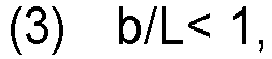
- a second aspect of the present invention is a device for manufacturing a fiber-reinforced resin molding material including a s separation portion having a plurality of cutting teeth for separating a continuous fiber tow into a plurality of fiber tows by piercing the fiber tow with the cutting teeth and a cutting portion for cutting the fiber tow processed in the separation portion at an interval in a longitudinal direction of the fiber tow, wherein the separation portion is configured to form at least two separation-processed lines extending in the longitudinal direction and arranged side by side in a width direction of the fiber tow by intermittently piercing the fiber tow with the cutting teeth, and the separation portion and the cutting portion are configured to operate so as to satisfy all of the following (1) to (3). 1 ⁇ c/L ⁇ 50 c ⁇ a b/L ⁇ 1
- the separation portion and the cutting portion may be configured to operate so as to further satisfy the following (4). 0.9 ⁇ a/ a + b ⁇ 1
- the separation portion may be configured to have a plurality of rotary blades which have each the cutting teeth arranged circumferentially and which are arranged at a predetermined interval in the width direction so as to provide the plurality of cutting teeth and so as to enable that the plurality of cutting teeth pierce the fiber tow while the plurality of rotary blades is rotated.
- the separation portion may be configured to have a plurality of saw blades which have each the cutting teeth arranged in the same direction as a transportation direction of the fiber tow and which are arranged at a predetermined interval in the width direction so as to provide the plurality of cutting teeth and so as to enable that the plurality of cutting teeth pierce the fiber tow while the plurality of saw blades is reciprocally moved close to and away from the fiber tow.
- the device for manufacturing a fiber-reinforced resin molding material may be configured so that a spacer member is further provided to be arranged between the plurality of rotary blades or between the plurality of saw blades, and so that in the separation portion, the plurality of cutting teeth pierce into the fiber tow until the spacer member comes into contact with the fiber tow.
- the device for manufacturing a fiber-reinforced resin molding material may further includes a first application portion for applying a paste including a resin onto a first sheet being transported in a predetermined direction, a second application portion for applying the paste onto a second sheet being transported in a predetermined direction, an impregnation portion configured to pressurize the paste between the first sheet and the second sheet overlaid together, a first transportation portion for transporting the first sheet with the paste applied thereon to the impregnation portion, and a second transportation portion for transporting the second sheet with the paste applied thereon to the impregnation portion, the cutting portion may be arranged so that cut fiber tows are sprinkled onto the paste on the first sheet, and the first transportation portion and the second transportation portion may be arranged so that the first sheet and the second sheet are overlaid together after the fiber tows are sprinkled onto the first sheet.
- a device for manufacturing a fiber-reinforced resin molding material including:
- the device for manufacturing a fiber-reinforced resin molding material according to the first aspect not recited in the claims may further include: a pair of guide members arranged on both sides in the transportation direction of the fiber tow and on a side opposite to the cutting teeth across the fiber tow, wherein the guide members support the fiber tow pierced by the plurality of cutting teeth.
- the device for manufacturing a fiber-reinforced resin molding material according to the first aspect not recited in the claims may further comprise:
- a value of the c/L is preferably 1.05 to 50, more preferably 1.05 to 30, still more preferably 1.05 to 20, particularly preferably 1.05 to 5, and most preferably 1.05 to 4.
- a value of the c and a value of the a preferably satisfy 1.1c ⁇ a, more preferably satisfy 1.5c ⁇ a, and still more preferably satisfy 2c ⁇ a.
- a value of the b/L is preferably more than zero and one or less and more preferably more than zero and 0.1 or less.
- a value of the a/(a+b) is preferably 0.92 to 0.99.
- a value of the c/L is preferably 1.05 to 50, more preferably 1.05 to 30, still more preferably 1.05 to 20, particularly preferably 1.05 to 5, and most preferably 1.05 to 4.
- a value of the c and a value of the a preferably satisfy 1.1c ⁇ a, more preferably satisfy 1.5c ⁇ a, and still more preferably satisfy 2c ⁇ a.
- a value of the b/L is preferably more than zero and one or less and more preferably more than zero and 0.1 or less.
- a value of the a/(a+b) may be 0.92 to 0.99.
- the method and the device for manufacturing a fiber-reinforced resin molding material of the present invention it is possible to stably supply a separated fiber tow to a cutting machine while maintaining a quality of a fiber-reinforced resin molding material to be manufactured and avoiding an influence of a meandering of a fiber tow or a skewing or meandering of a filament occurring in a fiber tow, and cut fiber tows are also easily dispersed.
- a method for manufacturing a fiber-reinforced resin molding material (hereinafter, the method and the material may be simply referred to respectively as “manufacturing method” and “molding material.") of the present embodiment is a method for manufacturing a sheet-like fiber-reinforced resin molding material obtained by making a resin penetrate between filaments of cut fiber tows and is applicable to manufacturing of SMC, and stampable sheets.
- the fiber tow refers to a plurality of reinforcing fibers bundled.
- a carbon fiber is preferred, but reinforcing fibers other than the carbon fiber such as a glass fiber may also be used.
- thermosetting resin and a thermoplastic resin can be used.
- a thermosetting resin may be used or only a thermoplastic resin may be used.
- both a thermosetting resin and a thermoplastic resin may be used.
- the resin used is preferably a thermosetting resin.
- the resin used is preferably a thermoplastic resin.
- thermosetting resin for example, an unsaturated polyester resin, an epoxy resin, a vinyl ester resin, a phenol resin, an epoxy acrylate resin, an urethane acrylate resin, a phenoxy resin, an alkyd resin, an urethane resin, a maleimide resin, and a cyanate resin, are exemplified. Only a single kind of thermosetting resin may be used or two or more thermosetting resins may be jointly used.
- thermoplastic resin for example, a polyolefin-based resin, a polyamidebased resin, a polyester-based resin, a polyphenylenesulfide resin, a polyether ketone resin, a polyether sulfone resin, and an aromatic polyamide resin, are exemplified. Only a single kind of thermoplastic resin may be used or two or more thermoplastic resins may be jointly used.
- the manufacturing method of the present embodiment includes a separation step of intermittently separating the fiber tow along a longitudinal direction thereof and forming at least two separation-processed lines extending in the longitudinal direction and arranged side by side in the width direction of the fiber tow and a cutting step of cutting the fiber tow after the separation step at an interval in the longitudinal direction.
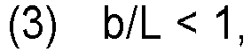
- a feature of the manufacturing method of the present embodiment is that the separation step and the cutting step are carried out so as to satisfy all of the following (1) to (3). 1 ⁇ c/L ⁇ 50 c ⁇ a b/L ⁇ 1
- "c” is an overlapping length of separated parts when one of the separation-processed lines is projected to another separation-processed line adjacent thereto in the width direction of the fiber tow.
- “L” is the cutting interval of the fiber tow in a cutting portion and is approximately equal to the length of the cut fiber tow.
- "a” is a length of a separated part in the separation-processed line.
- "b” is a length of an unseparated part in the separation-processed line.
- the inventors found that, when a fiber tow is separated and cut so as to satisfy the (1) to (3) in the separation step and the cutting step, it is possible to supply the separated fiber tow stably to a cutting machine and cut it while avoiding an influence of a skewing or meandering of a filament occurring in the fiber tow.
- the value of c/L is less than one, that is, the length c of the overlapping parts in the longitudinal direction of the separated parts of the adjacent separation-processed lines is shorter than the cutting interval L, at least two unseparated parts that are not divided are generated in each cut fiber tow, and every cut fiber tow inevitably becomes not fully divided in the width direction. Therefore, for example, at the time of manufacturing SMC, it becomes difficult to uniformly disperse the reinforced fibers and the impregnatability with the resin degrades, resulting in that the quality of SMC to be manufactured is likely to significantly degrade.
- the value of c/L is preferably 1.05 or more. Furthermore, when the value of c/L is 50 or less, even in a case where a skewing or meander of a filament exists in a fiber tow to be separated, the generation of fluff in cut fiber tows and a process trouble due to the fluff is reduced.
- the value of c/L is preferably 30 or less, more preferably 20 or less, still more preferably 5 or less, and particularly preferably 4 or less.
- the value of c/L is preferably 1.05 to 50, more preferably 1.05 to 30, still more preferably 1.05 to 20, particularly preferably 1.05 to 5, and most preferably 1.05 to 4.
- the value of a needs to be larger than the value of c, that is, c ⁇ a. This is because, in a case where the values of a and c are the same, unseparated parts lie in a row in the width direction in an individual cut fiber tow and there is a possibility that it may become difficult to uniformly disperse the reinforce fiber, for example, at the time of manufacturing SMC.
- 1.1c ⁇ a is preferred, 1.5c ⁇ a is more preferred, and 2c ⁇ a is still more preferred.
- the cut fiber tows inevitably become not fully divided in the width direction. Therefore, for example, at the time of manufacturing SMC, it becomes difficult to uniformly disperse the reinforced resin, the impregnatability with the resin degrades, resulting in that the quality of SMC to be manufactured is likely to significantly degrade. Therefore, in the manufacturing method of the present embodiment, it is essential that b/L is less than one. Furthermore, when the value of b/L is 0.1 or less, even in a case where a skewing or meander of a filament has occurred in a fiber tow, cut fiber tows easily disperse.
- the value of b/L is preferably more than zero and one or less and more preferably more than zero and 0.1 or less.
- a continuous fiber tow is intermittently separated in the longitudinal direction such that a condition of Expression (4) is satisfied and cut at an interval in the longitudinal direction to obtain cut fiber tows. 0 .9 ⁇ a/ a + b ⁇ 1
- the value of a/(a+b) is less than 0.9, the unseparated parts of the cut fiber tows are not easily divided, for example, at the time of sprinkling the fiber tows on a paste during the manufacturing of SMC, and thus it becomes difficult to uniformly disperse the reinforcing fiber on the paste, the impregnatability of the reinforcing fiber with the resin degrades, resulting in that the quality of SMC to be manufactured is likely to degrade.
- the value of a/(a+b) is more preferably 0.92 or more.
- this case corresponds to a situation in which the fiber tow is continuously separated in the longitudinal direction, and the value of a/(a+b) is one.
- the separated fiber tow is partially broken, and broken fiber tow may twine around a roll.
- the continuous fiber tow is intermittently separated in the longitudinal direction, and thus there is no case where there is no unseparated part (that is, b > 0). Therefore, a / (a+b) ⁇ 1 is satisfied at all times.
- the value of a / (a+b) is preferably 0.99 or less.
- the value of a / (a+b) is preferably 0.92 to 0.99.
- intermittently separating a continuous fiber tow it is preferable, from the viewpoint of better stability in separation of a fiber tow, to intermittently pierce the continuous fiber tow with a plurality of cutting teeth arranged serially at a predetermined interval in the width direction of the continuous fiber tow, thereby partially leaving the fiber tow unseparated in each space between parts where the fiber tow being separated into a plurality of fiber tows.
- the number of the plurality of cutting teeth arranged serially at a predetermined interval in the width direction of the continuous fiber tow only needs to be two or more and has no particular upper limit. As the number of cutting teeth used for separation per width of the fiber tow increases, the width of the cut fiber tow becomes narrower, and the quality of SMC to be manufactured further improves.
- the separation step is preferably carried out in an aspect in which positions of the tooth tip of a plurality of rotary blades are shifted therebetween in the direction of the fiber tow, the rotary blades having each a circumferentially arranged plurality of cutting teeth and being arranged side by side at a predetermined interval in the width direction of the continuous fiber tow, and the plurality of cutting teeth intermittently pierce the continuous fiber tow while the rotary blades are rotated.
- a saw blade having a plurality of cutting teeth arranged in the same direction as the transportation direction of the fiber tow is used and the plurality of cutting teeth intermittently pierce the continuous fiber tow while the saw blade is oscillated in the vertical direction is also preferred.
- the "cutting blade” refers to a plate-like member in which a tip, the part which first comes into contact with the fiber tow, is made slim and thin and the cross section of the tip is approximately wedge shaped.
- a material of the blade a hard material such as metal or ceramic is exemplified.
- the shape of the cutting tooth is not particularly limited as long as it can pierce a fiber tow.
- the maximum thickness of cutting tooth is preferably 0.3 to 2 mm at a part which comes into contact with a fiber tow.
- the maximum width of the cutting tooth is preferably 0.5 to 1.5 mm at a part which comes into contact with a fiber tow.
- the angle of the tip in the width direction of the cutting tooth is preferably 30° to 90°.
- the blade angle in the thickness direction of the cutting tooth is preferably 10° to 45° and more preferably 20° to 30°.
- the "tip angle” refers to an angle of a tip of a cutting tooth when the cutting tooth is plan-viewed.
- cutting edge angle refers to an angle of an edge of the cutting tooth when the cutting tooth is side-viewed.
- intermittently separating the continuous fiber tow means not using blades, for example, an aspect in which a gas such as an air is blown to the fiber tow under a predetermined condition can be exemplified. Even in such an aspect, it is possible to satisfy the (1) to (3) by, for example, intermittently blowing a gas to the fiber tow.
- Fiber tows obtained by cutting at an interval in the longitudinal direction after intermittently separating of a continuing fiber tow are dividable, such that, in the cut fiber tows, a weight proportion of one comprising tows remaining connected in the width direction through the unseparated parts and of which number is the same as the number the separation, that is, a fiber tow having a width that does not change before and after the cutting, is preferably 10% or less and more preferably 5% or less.
- the quality of a molding material to be manufactured degrades.
- the manufacturing method of the present invention essentially includes the separation step and the cutting step described above and, in the embodiment, may also include, in addition to the above-described steps, an application step, a sprinkling step, and an impregnation step described below.
- the manufacturing method of the embodiment which is executed with a device for manufacturing a fiber-reinforced resin molding material described below, includes the following steps.
- Application step A paste comprising a resin is applied onto a first sheet transported in a predetermined direction.
- Separation-processed lines are formed in a continuous fiber tow to separate the fiber tow into a plurality of fiber tows.
- Cutting step The fiber tow separated in the separation step are cut using a cutting machine.
- Sprinkling step The fiber tows cut in the cutting step are sprinkled onto the paste applied in the application step.
- Impregnation step A second sheet onto which a paste is applied is overlaid on the first sheet on which the fiber tows has been sprinkled in the sprinkling step, and then the paste and the fiber tows sandwiched between the first sheet and the second sheet are pressurized, thereby making the resin penetrate between filaments of the fiber tows.
- the continuous fiber tows may be transported in a state of being overlaid with each other in the thickness direction and separated into a plurality of fiber tows.
- a spreading step of spreading a continuous fiber tow in the width direction before the separation step may be further provided.
- a high-quality molding material can be manufactured from a relatively inexpensive large tow.
- an SMC manufacturing device shown in Fig. 1 and Fig. 2 will be specifically described.
- the SMC manufacturing device of the embodiment is an example of the manufacturing device of the present invention and a manufacturing device with which the manufacturing method of the present invention may be executed.
- the SMC manufacturing device of the embodiment is a device for manufacturing a sheet-like sheet molding compound (SMC) which comprises a fiber tow comprising a carbon fiber and a thermosetting resin comprising an unsaturated polyester resin and in which the thermosetting resin has penetrated between filaments of the fiber tows which have been cut.
- SMC sheet-like sheet molding compound
- the fiber tow in addition to the carbon fiber, a reinforcing fiber such as a glass fiber can be used.
- a thermoplastic resin can be used as the resin.
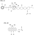
- Fig. 1 is a side view schematically showing the configuration of an SMC manufacturing device 1.
- Fig. 2A is a side view showing a configurational example of a fiber tow supply portion 10 provided in the SMC manufacturing device 1
- Fig. 2B is a front view of a separation portion, which is a part of the fiber tow supply portion 10, viewed from a transportation direction.
- the SMC manufacturing device 1 includes a fiber tow supply portion 10, a first sheet supply portion 11, a first application portion 12, a cutting portion 13, a second sheet supply portion 14, a second application portion 15, and an impregnation portion 16.
- the fiber tow supply portion 10 has a spreading portion configured to spread a continuous fiber tow CF in a width direction (Y-axis direction) while transporting the fiber tow in a predetermined direction (hereinafter, referred to as the transportation direction) and a separation portion configured to separate the spread fiber tow CF into a plurality of fiber tows CF.
- the fiber tow supply portion 10 of the embodiment includes a plurality of spreading bars 17 as the spreading portion and a plurality of rotary blades 18 and a plurality of godet rollers 19 as the separation portion, respectively.
- the fiber tow CF being a large tow pulled out from a bobbin B toward an X-axis positive direction (the right side in the horizontal direction) in Fig. 1 is spread in the width direction.
- the fiber tow CF passes through the plurality of spreading bars 17 constituting the spreading portion, heating, scraping, shaking, are carried out on the fiber tow CF through the respective spreading bars 17, whereby the fiber tow CF is broadened in the width direction and spread.
- separation-processed lines are formed on the spread fiber tow CF using the plurality of rotary blades 18 constituting the separation portion, and the fiber tow is separated into a plurality of fiber tows CF arranged in the width direction.
- the plurality of rotary blades 18 is arranged at a predetermined interval in the width direction of the spread fiber tow CF (Y-axis direction) so that the rotation centers coincide or substantially coincide with each other.
- a plurality of cutting teeth 18a is arranged side by side in the circumferential direction. Between the rotary blades 18, the plurality of cutting tooth 18a is preferably arranged at positions shifted from each other in the circumferential direction, thereby dispersion of the fiber tows CF after cutting can be facilitated.
- a ring-like spacer member 18b is arranged in each space between the rotary blades 18.
- the outer circumferential surface of the spacer member 18b is positioned slightly outward from the boundary between the cutting teeth 18a (a base of a cutting tooth).
- the cutting teeth 18a can not pierce deeper than the depth when the spacer member 18 comes in contact with the fiber tow CF, and thus it is possible to adjust the piercing depth of the cutting tooth 18a into the fiber tow CF by changing the positional relationship between the outer circumferential surface and the bases of the cutting teeth by exchanging the spacer member with another one having a different dimension. In a case where the adjustment is not required, the spacer member 18b may be removed.
- the plurality of rotary blades 18 is rotatably supported by a shaft member 18c extending through the rotation centers. Therefore, it is possible to rotate the plurality of rotary blades 18 in the same direction as the transportation direction of the fiber tow CF while piercing the fiber tow CF with the cutting teeth 18a in association with the transportation of the fiber tow CF.
- a configuration in which the plurality of rotary blades 18 is fixed to the shaft member 18c and the shaft member 18c and the plurality of rotary blades 18 are rotary-driven by a driving motor in synchronization with the transportation of the fiber tow CF may also be employed.
- a pair of guide members 40 is arranged so that the plurality of rotary blades 18 is arranged between them.
- the pair of guide members 40 is arranged opposite to the plurality of rotary blades 18 across the fiber tow CF.
- the plurality of rotary blades 18 comes close to the fiber tow CF moving between the pair of guide members 40 from a side opposite to the side on which the pair of guide members 40 is arranged, and the plurality of cutting teeth 18a pierce the fiber tow CF.
- the pair of guide members 40 supports the fiber tow CF pierced by the plurality of cutting teeth 18a such that the fiber tow does not move in the thickness direction, and thus the separation is suitably carried out with the plurality of cutting teeth 18a.
- the continuous fiber tow CF is intermittently pierced with the plurality of cutting teeth 18a while rotating each of the rotary blades 18, whereby the fiber tow CF is separated in the width direction.
- the plurality of cutting teeth 18a pierces up to a position at which the spacer members 18b come into contact with the continuous fiber tow CF, whereby the fiber tow CF is prevented from being continuously separated with the cutting teeth 18a.
- the fiber tow CF is not fully separated and is partially left unseparated in each space between parts where the fiber tow being separated into a plurality of fiber tows.
- the separated fiber tow CF is supplied toward the cutting portion 13 while being guided by the plurality of godet rollers 19.
- the first sheet supply portion 11 supplies a continuous first sheet S1 unwound from a first original roll R1 toward the first application portion 12.
- the SMC manufacturing device 1 includes a first transportation portion 20 configured to transport the first sheet S1 toward the impregnation portion 16.
- the first transportation portion 20 has a conveyor 23 having an endless belt 22 looped between a pair of pulleys 21a and 21b.
- the conveyor 23 rotates the pair of pulleys 21a and 21b in the same direction to orbit the endless belt 22 and transports the first sheet S1 in the X-axis positive direction shown in Fig. 1 on the surface of the endless belt 22.
- the first application portion 12 has a coater 24 that is arranged above the first sheet S 1 transported in the X-axis positive direction shown in Fig. 1 and supplies a paste P comprising a resin.
- the first sheet S 1 passes through the coater 24, whereby the paste P is applied onto a surface of the first sheet S1 in a predetermined thickness.
- the paste P it is possible to use a paste obtained by appropriately mixing, in addition to the above-described thermosetting resin such as an unsaturated polyester resin, a filler such as calcium carbonate, a low shrinking agent, a mold release agent, a curing initiator, or a viscosity improver.
- a filler such as calcium carbonate, a low shrinking agent, a mold release agent, a curing initiator, or a viscosity improver.
- the cutting portion 13 is provided downstream of the first application portion 12 in the transportation direction, cuts the fiber tow CF supplied from the fiber tow supply portion 10 using a cutting machine 13A, and sprinkles the cut fiber tows onto the paste P.
- the cutting machine 13A is disposed above the first sheet S1 transported by the conveyor 23 and has a guide roller 25, a pinch roller 26, and a cutter roller 27.
- the guide roller 25 guides the fiber tow CF supplied from the fiber tow supply portion 10 downward while rotating.
- the pinch roller 26 sandwiches the fiber tow CF with the guide roller 25 and rotates in the opposite direction to the guide roller 25, thereby drawing the separated fiber tow CF in cooperation with the guide roller 25.
- the cutter roller 27 cuts the fiber tow CF to a predetermined length while rotating. The cut fiber tows CF fall from between the guide roller 25 and the cutter roller 27 and are sprinkled onto the first sheet S1 onto which the paste P is applied.
- the cutting portion 13 executes the cutting step and the sprinkling step.
- the first transportation portion 20 transports the first sheet S1 on which the cut fiber tows CF are sprinkled to the impregnation portion 16.
- the second sheet supply portion 14 supplies a continuous second sheet S2 unwound from a second original roll R2 toward the second application portion 15.
- the SMC manufacturing device 1 includes a second transportation portion 28 configured to transport the second sheet S2 toward the impregnation portion 16.
- the second transportation portion 28 is disposed above the first sheet S1 transported by the conveyor 23 and has a plurality of guide rollers 29.
- the second transportation portion 28 transports the second sheet S2 supplied from the second sheet supply portion 14 in an X-axis negative direction (the left side in the horizontal direction) in Fig. 1 and then changes a direction in which the second sheet S2 is transported to a Z-axis negative direction (the down side in the vertical direction) in Fig. 1 and, furthermore, the X-axis positive direction by the plurality of rotating guide rollers 29.
- the second application portion 15 has a coater 30 that is disposed above the second sheet S2 transported in the X-axis negative direction and supplies the paste P.
- the second sheet S2 passes through the coater 30, whereby the paste P is applied onto a surface of the second sheet S2 in a predetermined thickness.
- the second transportation portion 28 transports the second sheet S2 to which the paste P is applied by the second application portion 15 to the impregnation portion 16.
- the impregnation portion 16 is disposed downstream of the cutting portion 13 in the transportation direction and has a lamination mechanism 31 and a pressurization mechanism 32.
- the lamination mechanism 31 is disposed above the downstream-side pulley 21b in the conveyor 23 and has a plurality of lamination rollers 33.
- the lamination rollers 33 are each arranged in a state of being in contact with a rear surface (paste P-free surface) of the second sheet S2 to which the paste P is applied. In addition, the lamination rollers 33 are each arranged such that the second sheet S2 gradually comes closer to the first sheet S1.
- the second sheet S2 is overlaid on the first sheet S1.
- the first sheet S1 and the second sheet S2 are transported to the pressurization mechanism 32 in a state of being laminated to each other while sandwiching the fiber tow CF and the paste P therebetween.
- the first sheet S1 and the second sheet S2 laminated to each other will be collectively referred to as a laminated sheet S3.
- the pressurization mechanism 32 is provided on the downstream side of the first transportation portion 20 (conveyor 23).
- the pressurization portion 32 has a lower conveyor 36A having an endless belt 35a looped between a pair of pulleys 34a and 34b and an upper conveyor 36B having an endless belt 35b looped between a pair of pulleys 34c and 34d.
- the lower conveyor 36A and the upper conveyor 36B are arranged to face each other in a state in which the endless belts 35a and 35b are looped.
- the pressurization mechanism 32 rotates the pair of pulleys 34a and 34b of the lower conveyor 36A in the same direction to orbit the endless belt 35a.
- the pair of pulleys 34c and 34d of the upper conveyor 36B rotate in the same direction and in a direction opposite to the pair of pulleys 34a and 34b, and the endless belt 35b is reversely orbited at the same speed as the endless belt 35a. Therefore, the laminated sheet S3 sandwiched between the endless belts 35a and 35b is transported in the X-axis positive direction in Fig. 1 .
- the pressurization mechanism 32 pressurizes the paste P and the fiber tows CF sandwiched between the first sheet S1 and the second sheet S2 using the plurality of lower rollers 37a and the plurality of upper rollers 37b while the laminated sheet S3 passes through between the endless belts 35a and 35b. At this time, the paste P penetrates between the filaments of the fiber tow CF from both sides across the fiber tow CF. Thereby, an original SMC R in which the thermosetting resin has penetrated between the filaments of the fiber tow CF is obtained.
- the long first sheet S 1 is unwound from the first original roll R1 and transported by the first transportation portion 20, and the paste P comprising a desired resin is applied onto the first sheet S1 using the first application portion 12 in a predetermined thickness.
- the fiber tow CF of a desired material is passed through between the plurality of spreading bars 17, thereby broadening the fiber tow CF in the width direction.
- the plurality of rotary blades 18 is disposed at a predetermined interval in the width direction of the fiber tow CF, positions of the cutting teeth 18a are shifted in the circumferential direction among the rotary blades, and the fiber tow CF is intermittently pierced with the plurality of cutting teeth 18a while the rotary blades 18 are rotated.
- a plurality of separation-processed lines for intermittently separating the fiber tow CF in the longitudinal direction are formed. In each of the separation-processed lines, parts not pierced by the cutting teeth 18a remain unseparated.
- the temperature of the fiber tow CF while being separated is preferably set to 60°C or lower and more preferably set to 5°C or higher and 50°C or lower in order to prevent adhesion between the separated fiber tows CF.
- a tow t being a spread fiber tow CF is indicated by a thin line
- a separation-processed line d of the spread fiber tow CF is indicated by a thick line
- a cutting line along which the spread fiber tow CF is cut using the cutting machine 13A is indicated by a broken line.
- separated parts a divided by the cutting teeth 18a and unseparated parts b not divided by the cutting teeth 18a are alternately arranged in the transportation direction, and thereby the separation-processed line d of perforation shape is formed.
- the fiber tow is partially left unseparated in each space between parts where the fiber tow being separated into a plurality of fiber tows, whereby it is possible to stably supply the separated fiber tow CF up to the cutting machine 13A of the cutting portion 13 while avoiding the influence of the meandering of the fiber tow CF or a skewing, meandering, or confounding of a filament having occurred in the fiber tow CF and to facilitate the dispersion of the fiber tows CF after cutting.
- the separation step and the cutting step are carried out such that the above mentioned expressions (1) to (3) are satisfied.
- the reinforcing fiber of the fiber tow CF is uniformly dispersed, and the impregnatability with the resin improves, whereby it becomes possible to manufacture a high-quality SMC.
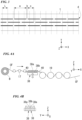
- a plurality of saw blades 38 as shown in Fig. 4A and Fig. 4B may be used.
- Fig. 4A is a side view showing another configurational example of the fiber tow supply portion which may be provided in the SMC manufacturing device 1
- Fig. 4B is a front view of the separation portion viewed from the transportation direction.
- the plurality of saw blades 38 is disposed side by side at a predetermined interval in the width direction of the spread fiber tow CF (Y-axis direction).
- a plurality of cutting teeth 38a is serially arranged in the same direction as the transportation direction of the fiber tow CF.
- positions of the plurality of cutting teeth 38a are preferably shifted in the longitudinal direction of the fiber tow CF. In such a case, it is possible to facilitate the dispersion of the fiber tows CF after cutting.
- a spacer member 38b is arranged between the every saw blade 38.
- the upper surface of the spacer member 38b is positioned slightly above the boundary between the cutting teeth 38a (a base of a cutting tooth).
- a pair of guide members 40 is disposed on both sides of the plurality of saw blades 38 in the transportation direction.
- the plurality of saw blades 38 is arranged so as to be capable of reciprocally moving (shaking) vertically between a position at which the plurality of cutting teeth 38a pierce the fiber tow CF transported between the pair of guide members 40 from a side opposite to the side on which the pair of guide members 40 is arranged and a position at which the plurality of cutting teeth 38a is away from the fiber tow CF transported between the pair of guide members 40.
- the spread fiber tow CF is intermittently pierced with the plurality of cutting teeth 38a while the saw blades 38 are reciprocally moved in the vertical direction (Z-axis direction), and thereby the fiber tow CF is separated in the width direction.
- the plurality of cutting teeth 38a is pierced up to a position at which the spacer members 38b come into contact with the continuous fiber tow CF, whereby the fiber tow CF is prevented from being continuously separated with the cutting teeth 38a.
- the continuous fiber tows CF may be overlaid with each other in the thickness direction and separated into a plurality of fiber tows CF in such a state.
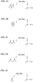
- the cutting teeth 18a and 38a only need to have a shape enabling intermittentl piercing of the fiber tow CF continuous in the transportation direction, and, for example, shapes of the cutting teeth 18a and 38a as shown in Fig. 5A to Fig. 5E may also be employed. Furthermore, the cutting teeth 18a and 38a may be a single-edged blade or a double-edged blade.
- the timings at which the cutting teeth 18a and 38a intermittently pierce the fiber tow CF may be matched or shifted.
- the plurality of rotary blades is staggeredly arranged in the width direction of the fiber tow CF or, between the rotary blades adjacent to each other, the shapes or arrangement of the cutting teeth are differentiated, whereby it is possible to satisfy the (2).
- the separation portion may be configured by combining the rotary blade 18 and the saw blade 38.
- a tip angle ⁇ shown in Fig. 6A and a cutting edge angle ⁇ shown in Fig. 6B are preferably set to satisfy any one or both of 30° ⁇ ⁇ ⁇ 90° and 10° ⁇ ⁇ ⁇ 45° (more preferably 20° ⁇ ⁇ ⁇ 30°).
- the thicknesses of the cutting teeth 18a and 38a are preferably set to 0.3 to 2 mm.
- the device for manufacturing a fiber-reinforced resin molding material of the present invention may not include the spreading portion. That is, a configuration in which spreading is carried out in a different device and the spread fiber tow is provided to the manufacturing device may be employed.
- SMC was manufactured using the above-described SMC manufacturing device 1.
- the separation portion provided with four rotary blades 18 was used.
- Each of the rotary blades 18 was provided with six cutting teeth 18a continuously arranged in the circumferential direction.
- Each of the cutting teeth 18a was of a substantially triangular shape in which the maximum thickness of a part that came into contact with the fiber tow CF was 1 mm, the maximum width of the part that came into contact with the fiber tow CF was 1 mm, the angle of a tip in the width direction (tip angle) was 64°, and the angle of an edge in the thickness direction (cutting edge angle) was 30°.
- the rotary blades 18 were installed to each have a position (phase) of the plurality of cutting teeth 18a in the circumferential direction shifted 30° relative to those of the rotary blade 18 adjacent thereto in the width direction of the fiber tow CF.
- the spacer member 18b was arranged between each space between the rotary blades 18, and the width of the spacer member 18b was 2.2 mm.
- the fiber tow CF a carbon fiber tow (manufactured by Mitsubishi Chemical Corporation, product name: TR50S15L, the number of fibers: 15,000 fibers) was used.
- the resin used in the paste P a vinyl ester resin was used.
- the fiber tow CF was broadened to a width of 15 mm.
- the transportation rate of the fiber tow CF during the separation was set to 40 m/min.
- four separation-processed lines were formed at an interval of 3 mm in the width direction of the fiber tow CF, such that 56.6 mm-long separated parts a and 0.5 mm-long unseparated parts b are alternately and continuously arranged in the longitudinal direction of the fiber tow CF and the distance c is 28.1 mm between two ends of separated parts selected respectively from two of the separation-processed lines being adjacent with each other in the width direction of the fiber tow CF to include no unseparated part therebetween.
- Cutting using the cutting machine 13A was carried out at an interval (L) of 25.4 mm in the longitudinal direction of the separated fiber tow CF.
- the cut fiber tows CF were sprinkled on the paste P applied onto the first sheet S1.
- the carbon fiber content of the manufactured fiber-reinforced resin molding material was 58%.
- Example 1 c/L was 1.11, c ⁇ a, b/L was 0.02, a/(a+b) was 0.99, and all of the above-described conditions of expressions (1) to (4) were satisfied.
- the length of a separated part a was set to 113.2 mm, which was twice the length in Example 1, and the length of an unseparated part b was set to 0.8 mm.
- the distance c between two ends of the separated parts selected respectively from two of the separation-processed lines being adjacent with each other in the width direction of the fiber tow CF to include no unseparated part therebetween was set to 56.2 mm, which was twice the distance in Example 1.
- SMC was manufactured in the same order as in Example 1 except for the above-described points.
- Example 2 c/L was 2.21, c ⁇ a, b/L was 0.03, a/(a+b) was 0.99, and all of the above-described conditions of expressions (1) to (4) were satisfied.
- the fiber tow CF, and the paste P As the SMC manufacturing device 1, the fiber tow CF, and the paste P, the same device, fiber tow, and paste as in Example 1 were used.
- the length of a separated part a was set to 259.0 mm, and the length of an unseparated part b was set to 1.0 mm.
- the distance c between two ends of the separated parts selected respectively from two of the separation-processed lines being adjacent with each other in the width direction of the fiber tow CF to include no unseparated part therebetween was set to 129.0 mm.
- SMC was manufactured in the same order as in Example 1 except for the above-described points.
- Example 3 c/L was 5.08, c ⁇ a, b/L was 0.04, a/(a+b) was 0.99, and all of the above-described conditions of expressions (1) to (4) were satisfied.
- the fiber tow CF, and the paste P As the SMC manufacturing device 1, the fiber tow CF, and the paste P, the same device, fiber tow, and paste as in Example 1 were used.
- Example 4 c/L was 32.4, c ⁇ a, b/L was 0.20, a/(a+b) was 0.99, and all of the above-described conditions of expressions (1) to (4) were satisfied.
- Example 2 The same SMC manufacturing device 1 as in Example 1 was used, but the four rotary blades 18 were installed such that the positions of the plurality of cutting teeth 18a in the circumferential direction all coincided with each other.
- the fiber tow CF and the paste P the same fiber tow and paste as in Example 1 were used.
- the length of a separated part a was set to 28.3 mm, which was half the length in Example 1.
- the distance c between two ends of the separated parts selected respectively from two of the separation-processed lines being adjacent with each other in the width direction of the fiber tow CF to include no separated part therebetween was 28.3 mm due to the above-described change in the installation of the rotary blades 18.
- SMC was manufactured in the same order as in Example 1 except for the above-described points.
- the fiber tow CF, and the paste P As the SMC manufacturing device 1, the fiber tow CF, and the paste P, the same device, fiber tow, and paste as in Example 1 were used.
- the length of a separated part a was set to 1,584.8 mm, and the length of an unseparated part b was set to 10 mm.
- the distance c between two ends of the separated parts selected respectively from two of the separation-processed lines being adjacent with each other in the width direction of the fiber tow CF to include no separated part therebetween was set to 1,558.8 mm.
- the number of tows remaining connected in one cut fiber tow CF was used.
- the cut fiber tows CF were sprinkled on the first sheet S 1 to which the resin was not applied and thereafter, the widths and lengths of a cut fiber tow picket out with tweezers was measured using a caliper in increments of 0.1 mm, and the weight of the cut fiber tow was measured using an electronic scale in increments of 0.1 mg. The number of samplings was set to 500.
- the number of filaments of a cut fiber tow was calculated using the following expression, and the ratio of a specific fiber tow to all of the fiber tows was obtained by counting a fiber tow with from 4,000 to less than 7,000 filaments as two connected tows, a fiber tow with from 7,000 to less than 10,000 filaments as three connected tows, a fiber tow with from 10,000 to less than 13,000 filaments as four connected tows, and a fiber tow with from 13,000 to 15,000 filaments as five connected tows.
- the number of filaments of a cut fiber tow [(the weight of the cut fiber tow) ⁇ (the number of filaments of the continuous carbon fiber used)] / [(the length of the cut fiber tow)]
- SMC of each example was disposed in a mold capable of processing flat plates and cured by being pressurized at 10 MPa and approximately 130°C for five minutes with a pressurization-type press, thereby obtaining a 300 ⁇ 300 (unit: mm) flat plate.
- test specimens Six 250 ⁇ 25 ⁇ 2 (unit: mm) test specimens were cut from the flat plate respectively along a 0° direction (X axis of the SMC manufacturing device 1) and along a 90° direction (12 specimens in total), tensile strengths were measured according to JIS K 7073, and the variation of the tensile strengths was calculated.
- Example 1 the separated fiber tows CF were stably supplied to the cutting portion 13 without a part thereof twining around a roll.
- the cut fiber tows CF two tows connected through the unseparated part were present as much as 38%, but three or more connected tows were not present, which did not affect the dispersibility of the fiber tows CF on the paste P.
- the manufactured SMC exhibited a mechanical characteristic almost the same as that of SMC which was obtained using a carbon fiber tow CF having a small number of filaments (the number of filaments: 3,000) without the separation step and comprised chopped carbon fiber tows of the same size as the carbon fiber tow.
- the variation of the tensile strengths was 8%, and there was no partial significant decrease in the strength.
- Example 2 the separated fiber tows CF were stably supplied to the cutting portion 13.
- the cut fiber tows CF two tows connected through the unseparated parts were present as much as 10%, but three or more connected tows were not present, which did not affect the dispersibility of the fiber tows CF on the paste P.
- the manufactured SMC exhibited a mechanical characteristic almost the same as that of SMC which was obtained using a carbon fiber tow CF having a small number of filaments (the number of filaments: 3,000) without the separation step and comprised chopped carbon fiber tows of the same size as the carbon fiber tow.
- the variation of the tensile strengths was 5%, and there was no partial significant decrease in the strength.
- Example 3 there were cases where a part of the separated fiber tows CF twined around a roll and the manufacturing of SMC was stopped, but the frequency was low, and the influence on the manufacturing was small.
- the manufactured SMC exhibited a mechanical characteristic almost the same as that of SMC which was obtained using a carbon fiber tow CF having a small number of filaments (the number of filaments: 3,000) without the separation step and comprised chopped carbon fiber tows of the same size as the carbon fiber tow.
- the variation of the tensile strengths was 4%, and there was no partial significant decrease in the strength.
- Comparative Example 1 there was no case where a part of the separated fiber tow CF twined around a roll, and the separated fiber tow were stably supplied to the cutting portion 13; however, in the cut fiber tows CF, five tows connected through the unseparated parts were present as much as 14%.
- the manufactured SMC partially exhibited a mechanical characteristic almost the same as that of SMC which was obtained using a carbon fiber tow CF having a small number of filaments (the number of filaments: 3,000) without the separation step and comprised chopped carbon fiber tows of the same size as the carbon fiber tow, and partially exhibited a poor mechanical characteristic.
- the variation of the tensile strengths was as great as 16%, and it was not possible to produce an original SMC R having a uniform mechanical characteristic.
- the method and the device for manufacturing a fiber-reinforced resin molding material of the present invention it is possible to maintain the quality of a fiber-reinforced resin molding material to be manufactured and stably supply a separated fiber tow up to a cutting machine while avoiding an influence of the meandering of the fiber tow or a skewing or meandering of a filament occurring in the fiber tow, and also the cut fiber tows are easily dispersed.
Landscapes
- Chemical & Material Sciences (AREA)
- Engineering & Computer Science (AREA)
- Mechanical Engineering (AREA)
- Materials Engineering (AREA)
- Forests & Forestry (AREA)
- Life Sciences & Earth Sciences (AREA)
- Manufacturing & Machinery (AREA)
- Health & Medical Sciences (AREA)
- Chemical Kinetics & Catalysis (AREA)
- Medicinal Chemistry (AREA)
- Polymers & Plastics (AREA)
- Organic Chemistry (AREA)
- Inorganic Chemistry (AREA)
- Composite Materials (AREA)
- Reinforced Plastic Materials (AREA)
Claims (15)
- Verfahren zur Herstellung von faserverstärktem Harzformmaterial, in dem ein geschnittener Faserstrang (CF) mit einem Harz imprägniert wird, wobei das Verfahren Folgendes einschließt:einen Trennschritt des intermittierenden Trennens eines Faserstrangs (CF) entlang einer Längsrichtung (X) davon und des Bildens von mindestens zwei trennungsverarbeiteten Linien (d), die sich in der Längsrichtung (X) erstrecken und nebeneinanderliegend in einer Breitenrichtung (Y) des Faserstrangs (CF) angeordnet sind; undeinen Schneideschritt des Schneidens des Faserstrangs (CF) nach dem Trennschritt in einem Abstand (L) in der Längsrichtung (X),dadurch gekennzeichnet, dassder Trennschritt und der Schneideschritt so ausgeführt werden, dass alle von (1) bis (3) unten erfüllt sind:


 wobei in (1) bis (3) "c" eine überlappende Länge getrennter Teile ist, wenn eine der trennungsverarbeiteten Linien (d) auf eine andere trennungsverarbeitete Linie (d) angrenzend dazu in der Breitenrichtung (Y) projiziert wird; "L" die Abstände im Schneideschritt sind; "a" eine Länge des getrennten Teils in der trennungsverarbeiteten Linie (d) ist; und "b" eine Länge eines ungetrennten Teils in der trennungsverarbeiteten Linie (d) ist.
- Verfahren zur Herstellung von faserverstärktem Harzformmaterial nach Anspruch 1, wobei der Trennschritt und der Schneideschritt so ausgeführt werden, dass sie weiter Folgendes (4) erfüllen.

- Verfahren zur Herstellung von faserverstärktem Harzformmaterial nach Anspruch 1 oder 2, wobei die trennungsverarbeiteten Linien (d) gebildet werden durch intermittierendes Durchstechen des Faserstrangs (CF) mit einer Vielzahl von Schneidezähnen (18a, 38a), die in einem vorbestimmten Abstand in der Breitenrichtung (Y) des Faserstrangs (CF) angeordnet sind.
- Verfahren zur Herstellung von faserverstärktem Harzformmaterial nach Anspruch 3, wobei die Vielzahl von Schneidezähnen (18a) bereitgestellt sind durch nebeneinanderliegendes Anordnen von der Vielzahl von Drehmessern (18) in einem vorbestimmten Abstand in der Breitenrichtung (Y), die jeweils die Schneidezähne (18a) in Umfangsrichtung angeordnet aufweisen, und die Vielzahl von Schneidezähnen (18a) den Faserstrang (CF) durchsticht, während die Vielzahl von Drehmessern (18) gedreht wird.
- Verfahren zur Herstellung von faserverstärktem Harzformmaterial nach Anspruch 3, wobei die Vielzahl von Schneidezähnen (38a) durch nebeneinanderliegendes Anordnen einer Vielzahl von Sägemessern (38) in einem vorbestimmten Abstand in der Breitenrichtung (Y) bereitgestellt sind, die jeweils die Schneidezähne (38a) entlang einer Transportrichtung (X) des Faserstrangs (CF) angeordnet aufweisen, und die Vielzahl von Schneidezähnen (38a) den Faserstrang (CF) durchsticht, während die Vielzahl von Sägemessern (38) abwechselnd zu dem Faserstrang (CF) hin und davon weg bewegt wird.
- Verfahren zur Herstellung von faserverstärktem Harzformmaterial nach einem der Ansprüche 1 bis 5, wobei der Trennschritt in einem Zustand ausgeführt wird, in dem eine Vielzahl von Fasersträngen (CF) zusammen überlagert wird.
- Verfahren zur Herstellung von faserverstärktem Harzformmaterial nach einem der Ansprüche 1 bis 6, wobei das Harz ein hitzehärtbares Harz ist.
- Verfahren zur Herstellung von faserverstärktem Harzformmaterial nach einem der Ansprüche 1 bis 7, wobei das Verfahren weiter Folgendes einschließt:
einen Schritt des Anwendens einer Paste (P), die das Harz umfasst, auf einen ersten Bogen, der in eine vorbestimmte Richtung (X) transportiert wird;einen Schritt des Streuens von geschnittenen Fasersträngen (CF) auf dem ersten Bogen (S1) mit der darauf angewendeten Paste (P); undeinen Schritt des Überlagerns eines zweiten Bogens (S2) mit einer darauf angewendeten Paste (P) über den ersten Bogen (S1) mit den darauf gestreuten Fasersträngen (CF) und dann des Beaufschlagens der Paste (P) und der zwischen dem ersten Bogen (S1) und dem zweiten Bogen (S2) eingeschobenen Faserstränge (CF) mit Druck, wodurch erreicht wird, dass das Harz zwischen Filamenten der Faserstränge (CF) eindringt. - Verfahren zur Herstellung von faserverstärktem Harzformmaterial nach einem der Ansprüche 1 bis 8, wobei das Verfahren weiter Folgendes einschließt:
einen Ausbreitungsschritt, der vor dem Trennschritt ausgeführt wird und zur Ausbreitung des Faserstrangs (CF) in der Breitenrichtung (Y) dient. - Verfahren zur Herstellung von faserverstärktem Harzformmaterial nach einem der Ansprüche 1 bis 9, wobei der Faserstrang (CF) ein Kohlenstoff-Faserstrang ist.
- Verwendung eines kontinuierlichen Faserstrangs (CF) in einem Verfahren zur Herstellung von faserverstärktem Harzformmaterial, in dem ein geschnittener Faserstrang (CF) mit einem Harz imprägniert wird, wobei das Verfahren Schneiden des kontinuierlichen Faserstrangs (CF) in einem Abstand (L) in der Längsrichtung (X) davon umfasst;
dadurch gekennzeichnet, dassder kontinuierliche Faserstrang (CF) mindestens zwei trennungsverarbeitete Linien (d) aufweist, die sich in der Längsrichtung (X) erstrecken und nebeneinanderliegend in einer Breitenrichtung (Y) des kontinuierlichen Faserstrangs (CF) angeordnet sind, der so gebildet ist, dass (2) unten erfüllt ist, und;wobei das Schneiden so ausgeführt wird, dass (1) und (3) unten erfüllt sind:

 wobei in (1) bis (3) "c" eine überlappende Länge getrennter Teile ist, wenn eine der trennungsverarbeiteten Linien (d) auf eine andere trennungsverarbeitete Linie (d) angrenzend dazu in der Breitenrichtung (Y) projiziert wird; "L" die Abstände im Schneiden sind; "a" eine Länge des getrennten Teils in der trennungsverarbeiteten Linie (d) ist; und "b" eine Länge eines ungetrennten Teils in der trennungsverarbeiteten Linie (d) ist.
- Verwendung nach Anspruch 11, wobei die trennungsverarbeiteten Linien (d) Folgendes (4) erfüllen.

- Verwendung nach Anspruch 11 oder 12, wobei der kontinuierliche Faserstrang (CF) ein Kohlenstoff-Faserstrang ist.
- Verwendung nach einem der Ansprüche 11 bis 13, wobei das Verfahren weiter Folgendes einschließt:
Anwenden einer Paste (P), die das Harz umfasst, auf einen ersten Bogen (S1), der in eine vorbestimmte Richtung (X) transportiert wird;Streuen von geschnittenen Fasersträngen (CF) auf dem ersten Bogen (S1) mit der darauf angewendeten Paste (P); undÜberlagern eines zweiten Bogens (S2) mit einer Paste (P), die das Harz darauf angewendet umfasst, auf dem ersten Bogen (S1) mit den darauf gestreuten Fasersträngen (CF) und dann Beaufschlagen der Paste (P) und der zwischen dem ersten Bogen (S1) und dem zweiten Bogen (S2) eingeschobenen Faserstränge (CF) mit Druck, wodurch erreicht wird, dass das Harz zwischen Filamenten der Faserstränge (CF) eindringt. - Verwendung nach einem der Ansprüche 11 bis 14, wobei das Harz ein hitzehärtbares Harz ist.
Priority Applications (1)
| Application Number | Priority Date | Filing Date | Title |
|---|---|---|---|
| EP24183709.5A EP4431554A3 (de) | 2017-11-20 | 2018-11-19 | Verfahren und vorrichtung zur herstellung von faserverstärkten harzformmassen |
Applications Claiming Priority (2)
| Application Number | Priority Date | Filing Date | Title |
|---|---|---|---|
| JP2017223119 | 2017-11-20 | ||
| PCT/JP2018/042700 WO2019098370A1 (ja) | 2017-11-20 | 2018-11-19 | 繊維強化樹脂成形材料の製造方法及び繊維強化樹脂成形材料製造装置 |
Related Child Applications (2)
| Application Number | Title | Priority Date | Filing Date |
|---|---|---|---|
| EP24183709.5A Division-Into EP4431554A3 (de) | 2017-11-20 | 2018-11-19 | Verfahren und vorrichtung zur herstellung von faserverstärkten harzformmassen |
| EP24183709.5A Division EP4431554A3 (de) | 2017-11-20 | 2018-11-19 | Verfahren und vorrichtung zur herstellung von faserverstärkten harzformmassen |
Publications (3)
| Publication Number | Publication Date |
|---|---|
| EP3715403A1 EP3715403A1 (de) | 2020-09-30 |
| EP3715403A4 EP3715403A4 (de) | 2021-02-17 |
| EP3715403B1 true EP3715403B1 (de) | 2024-10-23 |
Family
ID=66539067
Family Applications (2)
| Application Number | Title | Priority Date | Filing Date |
|---|---|---|---|
| EP18877503.5A Active EP3715403B1 (de) | 2017-11-20 | 2018-11-19 | Verfahren und vorrichtung zur herstellung von faserverstärktem harzformmaterial |
| EP24183709.5A Pending EP4431554A3 (de) | 2017-11-20 | 2018-11-19 | Verfahren und vorrichtung zur herstellung von faserverstärkten harzformmassen |
Family Applications After (1)
| Application Number | Title | Priority Date | Filing Date |
|---|---|---|---|
| EP24183709.5A Pending EP4431554A3 (de) | 2017-11-20 | 2018-11-19 | Verfahren und vorrichtung zur herstellung von faserverstärkten harzformmassen |
Country Status (6)
| Country | Link |
|---|---|
| US (1) | US11643513B2 (de) |
| EP (2) | EP3715403B1 (de) |
| JP (1) | JP6593557B2 (de) |
| CN (1) | CN111372977B (de) |
| ES (1) | ES2993480T3 (de) |
| WO (1) | WO2019098370A1 (de) |
Families Citing this family (7)
| Publication number | Priority date | Publication date | Assignee | Title |
|---|---|---|---|---|
| EP3919425B1 (de) | 2019-01-28 | 2024-03-27 | Mitsubishi Chemical Corporation | Faserpackung |
| CN119261248A (zh) | 2020-01-21 | 2025-01-07 | 三菱化学株式会社 | Smc的制造方法 |
| JP7604802B2 (ja) * | 2020-08-05 | 2024-12-24 | 三菱ケミカル株式会社 | Cf-smcおよびcf-smcの製造方法 |
| JP2024016302A (ja) * | 2020-12-17 | 2024-02-07 | 三菱ケミカル株式会社 | 接続部およびシートモールディングコンパウンドの製造方法 |
| CN112757368B (zh) * | 2020-12-30 | 2022-11-25 | 泰州远大家俬有限公司 | 一种塑材加工用定位高精度切割回收设备 |
| EP4650131A4 (de) * | 2023-01-12 | 2026-04-01 | Mitsubishi Chem Corp | Verfahren und vorrichtung zur herstellung einer kohlenstofffaserplattenformmasse |
| GB2638388A (en) * | 2023-12-20 | 2025-08-27 | Carbon Fiber Remanufacturing Llc | Remanufactured carbon fiber and related systems and methods |
Family Cites Families (11)
| Publication number | Priority date | Publication date | Assignee | Title |
|---|---|---|---|---|
| JP4617912B2 (ja) | 2005-02-10 | 2011-01-26 | 東レ株式会社 | 炭素繊維の分割方法、およびシートモールディングコンパウンドの製造方法 |
| US20120213997A1 (en) | 2011-02-21 | 2012-08-23 | United States Council For Automotive Research | Fiber tow treatment apparatus and system |
| US10392482B2 (en) | 2014-09-17 | 2019-08-27 | Toray Industries, Inc. | Fiber-reinforced resin molding material and production method thereof |
| US10676311B2 (en) | 2014-12-26 | 2020-06-09 | Toray Industries, Inc. | Method of manufacturing and manufacturing device for partial split-fiber fiber bundle and partial split-fiber fiber bundle |
| ES2887828T3 (es) * | 2015-07-07 | 2021-12-28 | Mitsubishi Chem Corp | Método para la producción de material de moldeo de resina reforzado con fibra |
| CN111674060A (zh) * | 2015-12-25 | 2020-09-18 | 三菱化学株式会社 | 碳纤维束的分纤方法 |
| CA3014524A1 (en) * | 2016-03-15 | 2017-09-21 | Toray Industries, Inc. | Fiber-reinforced resin molding material and production method therefor |
| EP3838536A3 (de) * | 2016-04-11 | 2021-09-22 | Mitsubishi Chemical Corporation | Verfahren zur herstellung von faserverstärktem harzmaterial und vorrichtung zur herstellung von faserverstärktem harzmaterial |
| JP2017223119A (ja) | 2016-06-13 | 2017-12-21 | トヨタ自動車株式会社 | 内燃機関の制御装置 |
| MX2018013777A (es) | 2016-06-21 | 2019-03-28 | Toray Industries | Haz de fibras parcialmente separado, metodo de produccion de haz de fibras parcialmente separado, material de moldeo de resina reforzado con fibra que usa un haz de fibras parcialmente separado y metodo de produccion de material de moldeo de resina reforzado con fibra que usa un haz de fibra parcialmente separado. |
| JP7035536B2 (ja) * | 2016-10-12 | 2022-03-15 | 東レ株式会社 | ランダムマットおよびその製造方法並びにそれを用いた繊維強化樹脂成形材料 |
-
2018
- 2018-11-19 EP EP18877503.5A patent/EP3715403B1/de active Active
- 2018-11-19 WO PCT/JP2018/042700 patent/WO2019098370A1/ja not_active Ceased
- 2018-11-19 CN CN201880074554.2A patent/CN111372977B/zh active Active
- 2018-11-19 ES ES18877503T patent/ES2993480T3/es active Active
- 2018-11-19 EP EP24183709.5A patent/EP4431554A3/de active Pending
- 2018-11-19 JP JP2018565081A patent/JP6593557B2/ja active Active
-
2020
- 2020-05-18 US US16/876,173 patent/US11643513B2/en active Active
Also Published As
| Publication number | Publication date |
|---|---|
| ES2993480T3 (en) | 2024-12-30 |
| US11643513B2 (en) | 2023-05-09 |
| EP3715403A4 (de) | 2021-02-17 |
| US20200277455A1 (en) | 2020-09-03 |
| EP3715403A1 (de) | 2020-09-30 |
| CN111372977A (zh) | 2020-07-03 |
| WO2019098370A1 (ja) | 2019-05-23 |
| EP4431554A2 (de) | 2024-09-18 |
| JPWO2019098370A1 (ja) | 2019-11-21 |
| CN111372977B (zh) | 2023-01-10 |
| JP6593557B2 (ja) | 2019-10-23 |
| EP4431554A3 (de) | 2024-12-11 |
Similar Documents
| Publication | Publication Date | Title |
|---|---|---|
| JP7201063B2 (ja) | 繊維強化樹脂成形材料の製造方法 | |
| US11643513B2 (en) | Method and device for manufacturing fiber-reinforced resin molding material | |
| US12023876B2 (en) | Method for producing fiber-reinforced resin molding material, and apparatus for producing fiber-reinforced resin molding material |
Legal Events
| Date | Code | Title | Description |
|---|---|---|---|
| STAA | Information on the status of an ep patent application or granted ep patent |
Free format text: STATUS: THE INTERNATIONAL PUBLICATION HAS BEEN MADE |
|
| PUAI | Public reference made under article 153(3) epc to a published international application that has entered the european phase |
Free format text: ORIGINAL CODE: 0009012 |
|
| STAA | Information on the status of an ep patent application or granted ep patent |
Free format text: STATUS: REQUEST FOR EXAMINATION WAS MADE |
|
| 17P | Request for examination filed |
Effective date: 20200520 |
|
| AK | Designated contracting states |
Kind code of ref document: A1 Designated state(s): AL AT BE BG CH CY CZ DE DK EE ES FI FR GB GR HR HU IE IS IT LI LT LU LV MC MK MT NL NO PL PT RO RS SE SI SK SM TR |
|
| AX | Request for extension of the european patent |
Extension state: BA ME |
|
| A4 | Supplementary search report drawn up and despatched |
Effective date: 20210115 |
|
| RIC1 | Information provided on ipc code assigned before grant |
Ipc: B26F 1/20 20060101ALI20210111BHEP Ipc: C08J 5/04 20060101AFI20210111BHEP Ipc: B26D 7/06 20060101ALI20210111BHEP Ipc: B26D 1/28 20060101ALI20210111BHEP Ipc: B26F 1/18 20060101ALI20210111BHEP Ipc: B26D 1/06 20060101ALI20210111BHEP Ipc: B26D 11/00 20060101ALI20210111BHEP |
|
| DAV | Request for validation of the european patent (deleted) | ||
| DAX | Request for extension of the european patent (deleted) | ||
| REG | Reference to a national code |
Ref country code: DE Ref legal event code: R079 Free format text: PREVIOUS MAIN CLASS: C08J0005040000 Ipc: C08J0005240000 Ref document number: 602018075837 Country of ref document: DE |
|
| GRAP | Despatch of communication of intention to grant a patent |
Free format text: ORIGINAL CODE: EPIDOSNIGR1 |
|
| STAA | Information on the status of an ep patent application or granted ep patent |
Free format text: STATUS: GRANT OF PATENT IS INTENDED |
|
| RIC1 | Information provided on ipc code assigned before grant |
Ipc: B26F 1/20 20060101ALI20240207BHEP Ipc: B26F 1/18 20060101ALI20240207BHEP Ipc: B26D 11/00 20060101ALI20240207BHEP Ipc: B26D 7/06 20060101ALI20240207BHEP Ipc: B26D 1/28 20060101ALI20240207BHEP Ipc: B26D 1/06 20060101ALI20240207BHEP Ipc: C08J 5/04 20060101ALI20240207BHEP Ipc: C08J 5/24 20060101AFI20240207BHEP |
|
| INTG | Intention to grant announced |
Effective date: 20240223 |
|
| GRAJ | Information related to disapproval of communication of intention to grant by the applicant or resumption of examination proceedings by the epo deleted |
Free format text: ORIGINAL CODE: EPIDOSDIGR1 |
|
| STAA | Information on the status of an ep patent application or granted ep patent |
Free format text: STATUS: REQUEST FOR EXAMINATION WAS MADE |
|
| REG | Reference to a national code |
Ref country code: DE Ref legal event code: R079 Free format text: PREVIOUS MAIN CLASS: C08J0005240000 Ipc: B29B0015120000 Ref document number: 602018075837 Country of ref document: DE |
|
| GRAP | Despatch of communication of intention to grant a patent |
Free format text: ORIGINAL CODE: EPIDOSNIGR1 |
|
| STAA | Information on the status of an ep patent application or granted ep patent |
Free format text: STATUS: GRANT OF PATENT IS INTENDED |
|
| INTC | Intention to grant announced (deleted) | ||
| INTG | Intention to grant announced |
Effective date: 20240705 |
|
| RIC1 | Information provided on ipc code assigned before grant |
Ipc: C08J 5/24 20060101ALI20240621BHEP Ipc: B26F 1/20 20060101ALI20240621BHEP Ipc: B26F 1/18 20060101ALI20240621BHEP Ipc: B26D 11/00 20060101ALI20240621BHEP Ipc: B26D 7/06 20060101ALI20240621BHEP Ipc: B26D 1/28 20060101ALI20240621BHEP Ipc: B26D 1/06 20060101ALI20240621BHEP Ipc: C08J 5/04 20060101ALI20240621BHEP Ipc: B29B 15/12 20060101AFI20240621BHEP |
|
| GRAS | Grant fee paid |
Free format text: ORIGINAL CODE: EPIDOSNIGR3 |
|
| P01 | Opt-out of the competence of the unified patent court (upc) registered |
Free format text: CASE NUMBER: APP_47157/2024 Effective date: 20240814 |
|
| GRAA | (expected) grant |
Free format text: ORIGINAL CODE: 0009210 |
|
| STAA | Information on the status of an ep patent application or granted ep patent |
Free format text: STATUS: THE PATENT HAS BEEN GRANTED |
|
| AK | Designated contracting states |
Kind code of ref document: B1 Designated state(s): AL AT BE BG CH CY CZ DE DK EE ES FI FR GB GR HR HU IE IS IT LI LT LU LV MC MK MT NL NO PL PT RO RS SE SI SK SM TR |
|
| REG | Reference to a national code |
Ref country code: GB Ref legal event code: FG4D |
|
| REG | Reference to a national code |
Ref country code: CH Ref legal event code: EP |
|
| REG | Reference to a national code |
Ref country code: DE Ref legal event code: R096 Ref document number: 602018075837 Country of ref document: DE |
|
| REG | Reference to a national code |
Ref country code: IE Ref legal event code: FG4D |
|
| REG | Reference to a national code |
Ref country code: ES Ref legal event code: FG2A Ref document number: 2993480 Country of ref document: ES Kind code of ref document: T3 Effective date: 20241230 |
|
| REG | Reference to a national code |
Ref country code: LT Ref legal event code: MG9D |
|
| REG | Reference to a national code |
Ref country code: NL Ref legal event code: MP Effective date: 20241023 |
|
| REG | Reference to a national code |
Ref country code: AT Ref legal event code: MK05 Ref document number: 1734492 Country of ref document: AT Kind code of ref document: T Effective date: 20241023 |
|
| PG25 | Lapsed in a contracting state [announced via postgrant information from national office to epo] |
Ref country code: NL Free format text: LAPSE BECAUSE OF FAILURE TO SUBMIT A TRANSLATION OF THE DESCRIPTION OR TO PAY THE FEE WITHIN THE PRESCRIBED TIME-LIMIT Effective date: 20241023 |
|
| PG25 | Lapsed in a contracting state [announced via postgrant information from national office to epo] |
Ref country code: NL Free format text: LAPSE BECAUSE OF FAILURE TO SUBMIT A TRANSLATION OF THE DESCRIPTION OR TO PAY THE FEE WITHIN THE PRESCRIBED TIME-LIMIT Effective date: 20241023 |
|
| PG25 | Lapsed in a contracting state [announced via postgrant information from national office to epo] |
Ref country code: IS Free format text: LAPSE BECAUSE OF FAILURE TO SUBMIT A TRANSLATION OF THE DESCRIPTION OR TO PAY THE FEE WITHIN THE PRESCRIBED TIME-LIMIT Effective date: 20250223 Ref country code: PT Free format text: LAPSE BECAUSE OF FAILURE TO SUBMIT A TRANSLATION OF THE DESCRIPTION OR TO PAY THE FEE WITHIN THE PRESCRIBED TIME-LIMIT Effective date: 20250224 Ref country code: HR Free format text: LAPSE BECAUSE OF FAILURE TO SUBMIT A TRANSLATION OF THE DESCRIPTION OR TO PAY THE FEE WITHIN THE PRESCRIBED TIME-LIMIT Effective date: 20241023 |
|
| PG25 | Lapsed in a contracting state [announced via postgrant information from national office to epo] |
Ref country code: FI Free format text: LAPSE BECAUSE OF FAILURE TO SUBMIT A TRANSLATION OF THE DESCRIPTION OR TO PAY THE FEE WITHIN THE PRESCRIBED TIME-LIMIT Effective date: 20241023 |
|
| PG25 | Lapsed in a contracting state [announced via postgrant information from national office to epo] |
Ref country code: BG Free format text: LAPSE BECAUSE OF FAILURE TO SUBMIT A TRANSLATION OF THE DESCRIPTION OR TO PAY THE FEE WITHIN THE PRESCRIBED TIME-LIMIT Effective date: 20241023 |
|
| PG25 | Lapsed in a contracting state [announced via postgrant information from national office to epo] |
Ref country code: NO Free format text: LAPSE BECAUSE OF FAILURE TO SUBMIT A TRANSLATION OF THE DESCRIPTION OR TO PAY THE FEE WITHIN THE PRESCRIBED TIME-LIMIT Effective date: 20250123 |
|
| PG25 | Lapsed in a contracting state [announced via postgrant information from national office to epo] |
Ref country code: LV Free format text: LAPSE BECAUSE OF FAILURE TO SUBMIT A TRANSLATION OF THE DESCRIPTION OR TO PAY THE FEE WITHIN THE PRESCRIBED TIME-LIMIT Effective date: 20241023 Ref country code: AT Free format text: LAPSE BECAUSE OF FAILURE TO SUBMIT A TRANSLATION OF THE DESCRIPTION OR TO PAY THE FEE WITHIN THE PRESCRIBED TIME-LIMIT Effective date: 20241023 Ref country code: GR Free format text: LAPSE BECAUSE OF FAILURE TO SUBMIT A TRANSLATION OF THE DESCRIPTION OR TO PAY THE FEE WITHIN THE PRESCRIBED TIME-LIMIT Effective date: 20250124 |
|
| PG25 | Lapsed in a contracting state [announced via postgrant information from national office to epo] |
Ref country code: PL Free format text: LAPSE BECAUSE OF FAILURE TO SUBMIT A TRANSLATION OF THE DESCRIPTION OR TO PAY THE FEE WITHIN THE PRESCRIBED TIME-LIMIT Effective date: 20241023 |
|
| PG25 | Lapsed in a contracting state [announced via postgrant information from national office to epo] |
Ref country code: RS Free format text: LAPSE BECAUSE OF FAILURE TO SUBMIT A TRANSLATION OF THE DESCRIPTION OR TO PAY THE FEE WITHIN THE PRESCRIBED TIME-LIMIT Effective date: 20250123 |
|
| REG | Reference to a national code |
Ref country code: DE Ref legal event code: R119 Ref document number: 602018075837 Country of ref document: DE |
|
| REG | Reference to a national code |
Ref country code: CH Ref legal event code: PL |
|
| PG25 | Lapsed in a contracting state [announced via postgrant information from national office to epo] |
Ref country code: SM Free format text: LAPSE BECAUSE OF FAILURE TO SUBMIT A TRANSLATION OF THE DESCRIPTION OR TO PAY THE FEE WITHIN THE PRESCRIBED TIME-LIMIT Effective date: 20241023 |
|
| PG25 | Lapsed in a contracting state [announced via postgrant information from national office to epo] |
Ref country code: MC Free format text: LAPSE BECAUSE OF FAILURE TO SUBMIT A TRANSLATION OF THE DESCRIPTION OR TO PAY THE FEE WITHIN THE PRESCRIBED TIME-LIMIT Effective date: 20241023 |
|
| PG25 | Lapsed in a contracting state [announced via postgrant information from national office to epo] |
Ref country code: DK Free format text: LAPSE BECAUSE OF FAILURE TO SUBMIT A TRANSLATION OF THE DESCRIPTION OR TO PAY THE FEE WITHIN THE PRESCRIBED TIME-LIMIT Effective date: 20241023 |
|
| PG25 | Lapsed in a contracting state [announced via postgrant information from national office to epo] |
Ref country code: LU Free format text: LAPSE BECAUSE OF NON-PAYMENT OF DUE FEES Effective date: 20241119 |
|
| REG | Reference to a national code |
Ref country code: CH Ref legal event code: PL |
|
| PG25 | Lapsed in a contracting state [announced via postgrant information from national office to epo] |
Ref country code: EE Free format text: LAPSE BECAUSE OF FAILURE TO SUBMIT A TRANSLATION OF THE DESCRIPTION OR TO PAY THE FEE WITHIN THE PRESCRIBED TIME-LIMIT Effective date: 20241023 |
|
| PG25 | Lapsed in a contracting state [announced via postgrant information from national office to epo] |
Ref country code: CH Free format text: LAPSE BECAUSE OF NON-PAYMENT OF DUE FEES Effective date: 20241130 |
|
| PG25 | Lapsed in a contracting state [announced via postgrant information from national office to epo] |
Ref country code: RO Free format text: LAPSE BECAUSE OF FAILURE TO SUBMIT A TRANSLATION OF THE DESCRIPTION OR TO PAY THE FEE WITHIN THE PRESCRIBED TIME-LIMIT Effective date: 20241023 |
|
| PG25 | Lapsed in a contracting state [announced via postgrant information from national office to epo] |
Ref country code: SK Free format text: LAPSE BECAUSE OF FAILURE TO SUBMIT A TRANSLATION OF THE DESCRIPTION OR TO PAY THE FEE WITHIN THE PRESCRIBED TIME-LIMIT Effective date: 20241023 |
|
| PG25 | Lapsed in a contracting state [announced via postgrant information from national office to epo] |
Ref country code: CZ Free format text: LAPSE BECAUSE OF FAILURE TO SUBMIT A TRANSLATION OF THE DESCRIPTION OR TO PAY THE FEE WITHIN THE PRESCRIBED TIME-LIMIT Effective date: 20241023 |
|
| PG25 | Lapsed in a contracting state [announced via postgrant information from national office to epo] |
Ref country code: IT Free format text: LAPSE BECAUSE OF FAILURE TO SUBMIT A TRANSLATION OF THE DESCRIPTION OR TO PAY THE FEE WITHIN THE PRESCRIBED TIME-LIMIT Effective date: 20241023 |
|
| REG | Reference to a national code |
Ref country code: BE Ref legal event code: MM Effective date: 20241130 |
|
| PLBE | No opposition filed within time limit |
Free format text: ORIGINAL CODE: 0009261 |
|
| STAA | Information on the status of an ep patent application or granted ep patent |
Free format text: STATUS: NO OPPOSITION FILED WITHIN TIME LIMIT |
|
| PG25 | Lapsed in a contracting state [announced via postgrant information from national office to epo] |
Ref country code: SE Free format text: LAPSE BECAUSE OF FAILURE TO SUBMIT A TRANSLATION OF THE DESCRIPTION OR TO PAY THE FEE WITHIN THE PRESCRIBED TIME-LIMIT Effective date: 20241023 |
|
| GBPC | Gb: european patent ceased through non-payment of renewal fee |
Effective date: 20250123 |
|
| 26N | No opposition filed |
Effective date: 20250724 |
|
| PG25 | Lapsed in a contracting state [announced via postgrant information from national office to epo] |
Ref country code: DE Free format text: LAPSE BECAUSE OF NON-PAYMENT OF DUE FEES Effective date: 20250603 |
|
| PG25 | Lapsed in a contracting state [announced via postgrant information from national office to epo] |
Ref country code: GB Free format text: LAPSE BECAUSE OF NON-PAYMENT OF DUE FEES Effective date: 20250123 Ref country code: BE Free format text: LAPSE BECAUSE OF NON-PAYMENT OF DUE FEES Effective date: 20241130 |
|
| PG25 | Lapsed in a contracting state [announced via postgrant information from national office to epo] |
Ref country code: FR Free format text: LAPSE BECAUSE OF NON-PAYMENT OF DUE FEES Effective date: 20241223 |
|
| PG25 | Lapsed in a contracting state [announced via postgrant information from national office to epo] |
Ref country code: IE Free format text: LAPSE BECAUSE OF NON-PAYMENT OF DUE FEES Effective date: 20241119 |
|
| PGFP | Annual fee paid to national office [announced via postgrant information from national office to epo] |
Ref country code: ES Payment date: 20251223 Year of fee payment: 8 |
|
| PG25 | Lapsed in a contracting state [announced via postgrant information from national office to epo] |
Ref country code: HU Free format text: LAPSE BECAUSE OF FAILURE TO SUBMIT A TRANSLATION OF THE DESCRIPTION OR TO PAY THE FEE WITHIN THE PRESCRIBED TIME-LIMIT; INVALID AB INITIO Effective date: 20181119 |
|
| PG25 | Lapsed in a contracting state [announced via postgrant information from national office to epo] |
Ref country code: CY Free format text: LAPSE BECAUSE OF FAILURE TO SUBMIT A TRANSLATION OF THE DESCRIPTION OR TO PAY THE FEE WITHIN THE PRESCRIBED TIME-LIMIT; INVALID AB INITIO Effective date: 20181119 |
|
| PG25 | Lapsed in a contracting state [announced via postgrant information from national office to epo] |
Ref country code: TR Free format text: LAPSE BECAUSE OF FAILURE TO SUBMIT A TRANSLATION OF THE DESCRIPTION OR TO PAY THE FEE WITHIN THE PRESCRIBED TIME-LIMIT Effective date: 20241023 |
|
| PG25 | Lapsed in a contracting state [announced via postgrant information from national office to epo] |
Ref country code: SI Free format text: LAPSE BECAUSE OF FAILURE TO SUBMIT A TRANSLATION OF THE DESCRIPTION OR TO PAY THE FEE WITHIN THE PRESCRIBED TIME-LIMIT Effective date: 20241023 |
|
| PG25 | Lapsed in a contracting state [announced via postgrant information from national office to epo] |
Ref country code: LT Free format text: LAPSE BECAUSE OF FAILURE TO SUBMIT A TRANSLATION OF THE DESCRIPTION OR TO PAY THE FEE WITHIN THE PRESCRIBED TIME-LIMIT Effective date: 20241023 |