EP3715150B1 - System und verfahren zur kontrolle eines reifendrucks - Google Patents
System und verfahren zur kontrolle eines reifendrucks Download PDFInfo
- Publication number
- EP3715150B1 EP3715150B1 EP20154471.5A EP20154471A EP3715150B1 EP 3715150 B1 EP3715150 B1 EP 3715150B1 EP 20154471 A EP20154471 A EP 20154471A EP 3715150 B1 EP3715150 B1 EP 3715150B1
- Authority
- EP
- European Patent Office
- Prior art keywords
- sensor device
- telematics
- spatial position
- basis
- computer cloud
- Prior art date
- Legal status (The legal status is an assumption and is not a legal conclusion. Google has not performed a legal analysis and makes no representation as to the accuracy of the status listed.)
- Active
Links
Images

Classifications
-
- B—PERFORMING OPERATIONS; TRANSPORTING
- B60—VEHICLES IN GENERAL
- B60C—VEHICLE TYRES; TYRE INFLATION; TYRE CHANGING; CONNECTING VALVES TO INFLATABLE ELASTIC BODIES IN GENERAL; DEVICES OR ARRANGEMENTS RELATED TO TYRES
- B60C23/00—Devices for measuring, signalling, controlling, or distributing tyre pressure or temperature, specially adapted for mounting on vehicles; Arrangement of tyre inflating devices on vehicles, e.g. of pumps or of tanks; Tyre cooling arrangements
- B60C23/001—Devices for manually or automatically controlling or distributing tyre pressure whilst the vehicle is moving
- B60C23/002—Devices for manually or automatically controlling or distributing tyre pressure whilst the vehicle is moving by monitoring conditions other than tyre pressure or deformation
-
- B—PERFORMING OPERATIONS; TRANSPORTING
- B60—VEHICLES IN GENERAL
- B60C—VEHICLE TYRES; TYRE INFLATION; TYRE CHANGING; CONNECTING VALVES TO INFLATABLE ELASTIC BODIES IN GENERAL; DEVICES OR ARRANGEMENTS RELATED TO TYRES
- B60C23/00—Devices for measuring, signalling, controlling, or distributing tyre pressure or temperature, specially adapted for mounting on vehicles; Arrangement of tyre inflating devices on vehicles, e.g. of pumps or of tanks; Tyre cooling arrangements
- B60C23/001—Devices for manually or automatically controlling or distributing tyre pressure whilst the vehicle is moving
- B60C23/004—Devices for manually or automatically controlling or distributing tyre pressure whilst the vehicle is moving the control being done on the wheel, e.g. using a wheel-mounted reservoir
-
- B—PERFORMING OPERATIONS; TRANSPORTING
- B60—VEHICLES IN GENERAL
- B60C—VEHICLE TYRES; TYRE INFLATION; TYRE CHANGING; CONNECTING VALVES TO INFLATABLE ELASTIC BODIES IN GENERAL; DEVICES OR ARRANGEMENTS RELATED TO TYRES
- B60C23/00—Devices for measuring, signalling, controlling, or distributing tyre pressure or temperature, specially adapted for mounting on vehicles; Arrangement of tyre inflating devices on vehicles, e.g. of pumps or of tanks; Tyre cooling arrangements
- B60C23/02—Signalling devices actuated by tyre pressure
- B60C23/04—Signalling devices actuated by tyre pressure mounted on the wheel or tyre
- B60C23/0408—Signalling devices actuated by tyre pressure mounted on the wheel or tyre transmitting the signals by non-mechanical means from the wheel or tyre to a vehicle body mounted receiver
- B60C23/0479—Communicating with external units being not part of the vehicle, e.g. tools for diagnostic, mobile phones, electronic keys or service stations
-
- B—PERFORMING OPERATIONS; TRANSPORTING
- B60—VEHICLES IN GENERAL
- B60C—VEHICLE TYRES; TYRE INFLATION; TYRE CHANGING; CONNECTING VALVES TO INFLATABLE ELASTIC BODIES IN GENERAL; DEVICES OR ARRANGEMENTS RELATED TO TYRES
- B60C23/00—Devices for measuring, signalling, controlling, or distributing tyre pressure or temperature, specially adapted for mounting on vehicles; Arrangement of tyre inflating devices on vehicles, e.g. of pumps or of tanks; Tyre cooling arrangements
- B60C23/02—Signalling devices actuated by tyre pressure
- B60C23/04—Signalling devices actuated by tyre pressure mounted on the wheel or tyre
- B60C23/0491—Constructional details of means for attaching the control device
- B60C23/0493—Constructional details of means for attaching the control device for attachment on the tyre
Definitions
- the present invention relates to a system and a method.
- the present invention is based on a system for controlling tire pressure.
- the system has a sensor device, wherein the sensor device is provided for detecting tire pressure.
- the system has a central control unit, a telematics device and an evaluation device.
- the telematics device is provided for information processing and information transmission.
- the evaluation device is provided in particular for evaluating data.
- the invention is therefore based on the object of providing a system for controlling an internal tire pressure, with which a target tire pressure or a desired tire pressure can be assigned to a vehicle surface in a simplified and reliable manner.
- the telematics device is set up to receive signals from a global navigation satellite system and is set up to exchange data and signals with the evaluation device, wherein the position data of the sensor device can be determined on the basis of the signals by means of the telematics device, and wherein the evaluation device is set up to assign a unique target pressure value range to the position data of the sensor device.
- the telematics device is set up to receive signals from a global navigation satellite system and is set up to exchange data and signals with the evaluation device, wherein the position data of the sensor device can be determined using the signals by means of the telematics device, and wherein the evaluation device is set up to assign a unique target pressure value range to the position data of the sensor device
- a system is provided in which a target pressure value range can be automatically assigned to a specific road surface that is associated with the position data of the sensor device within a tire. In this way, a tire's internal pressure can be automatically adapted to a ground condition.
- the invention further relates to a method having the features of claim 5.
- the system has a warning device.
- the warning device is designed to emit an acoustic or optical warning signal depending on a signal from the evaluation device.
- the system has a warning device, wherein the warning device is designed to emit an acoustic or optical warning signal depending on a signal from the evaluation device, a driver of the vehicle whose tires are monitored with regard to their respective tire pressure can be immediately informed of such a situation. where, for example, the tire pressure is too high or too low.
- a tire pressure that is too high or too low occurs when the measured tire pressure is outside the assigned target pressure range.
- the system has a transmitting device.
- the transmitting device is designed to transmit a reference signal, which is a reference signal that can be received by the telematics device and the reference signal can be used to determine a spatial position of the sensor device, the telematics device being designed to compare the position data of the sensor device with the spatial position of the sensor device determined by means of the reference signal.
- the system has a pressure-changing device.
- the pressure-changing device is designed to change a pressure in a pneumatic tire.
- the pressure-changing device is designed in particular to change the tire's internal pressure depending on a signal from the telematics device.
- the pressure changing device can be configured to change the tire internal pressure in dependence on a signal from the computer network device.
- the computer network device may also be referred to as a computer cloud.
- the pressure changing device may, for example, be a device for increasing or decreasing an air pressure within the tire.
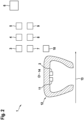
- a system 1 according to the invention for controlling the internal tire pressure of a tire 12 is shown schematically.
- the tire 12 is shown in a radial sectional view as being rotatable about a rotation axis 13 in a direction of rotation 14.
- the system 1 has a sensor device 2, wherein the sensor device 2 is provided for detecting the internal tire pressure.
- the system 1 also has a central control unit 3, a telematics device 4, wherein the telematics device 4 is provided for information processing and for information transmission, and an evaluation device 5.
- the telematics device 4 is set up to receive signals from a global navigation satellite system 6.
- the telematics device 4 is also set up to exchange data and signals with the evaluation device 5.
- the position data of the sensor device 2 can be determined using the signals using the telematics device 4.
- the evaluation device 5 is set up to assign a unique target pressure to the position data of the sensor device 2.
- the system 1 has a warning device 7.
- the warning device 7 is designed to output an acoustic or optical warning signal depending on a signal from the evaluation device 5.
- the system 1 has in particular a computer network device 8.
- the computer network device 8 is set up to exchange data and signals with the telematics device 4.
- the computer network device 8 is also set up to process and analyze the data and signals, wherein the computer network device 8 is set up to transmit the data or the processed data to a further device 9.
- a system 1 according to the invention is shown schematically according to an embodiment. According to the representation in the Figure 2 the system 1 has a transmitting device 10.
- the transmitting device 10 is configured to transmit a reference signal, which is a reference signal that can be received by the telematics device 4 and the reference signal can be used to determine a spatial position of the sensor device 2, the telematics device 4 being configured to compare the position data of the sensor device 2 with the spatial position of the sensor device 2 determined by means of the reference signal.
- a reference signal which is a reference signal that can be received by the telematics device 4 and the reference signal can be used to determine a spatial position of the sensor device 2, the telematics device 4 being configured to compare the position data of the sensor device 2 with the spatial position of the sensor device 2 determined by means of the reference signal.
- the system 1 according to the invention has in particular a pressure changing device 11.
- the pressure changing device 11 is designed to change a pressure in a tire 12.
Landscapes
- Engineering & Computer Science (AREA)
- Mechanical Engineering (AREA)
- Measuring Fluid Pressure (AREA)
Description
- Die vorliegende Erfindung bezieht sich auf ein System und auf ein Verfahren.
- Die vorliegende Erfindung geht aus von einem System zur Kontrolle eines Reifeninnendrucks. Das System weist eine Sensorvorrichtung auf, wobei die Sensorvorrichtung zur Erfassung eines Reifeninnendruckes vorgesehen ist. Das System weist eine zentrale Steuereinheit, eine Telematik-Vorrichtung und eine Auswertevorrichtung auf. Dabei ist die Telematik-Vorrichtung zur Informationsverarbeitung und zur Informationsübertragung vorgesehen. Die Auswertevorrichtung ist insbesondere zu einer Auswertung von Daten vorgesehen.
- Aus dem Stand der Technik sind Systeme zur Kontrolle eines Reifeninnendruckes bekannt, beispielsweise aus der
KR 101490920B1 - Dabei ist es aus dem Stand der Technik auch bekannt, mittels der Systeme einen Reifeninnendruck in Abhängigkeit des Einsatzortes des Reifens zu bewerten. So kann es beispielsweise erforderlich sein, für verschiedene Bereiche, auf denen ein Reifen abrollt, unterschiedliche Reifeninnendrücke vorzusehen und einzustellen. Beispielsweise kann ein optimaler Reifeninnendruck auf einem unebenen Gelände ein anderer sein, als es ein optimaler Reifeninnendruck auf einer asphaltierten und ebenen Straße ist. Für den Fall, wonach für verschiedene Bereiche, auf denen ein Reifen abrollt, unterschiedliche Reifeninnendrücke vorgesehen sind, kann es demnach sinnvoll sein, einen aktuellen Reifeninnendruck in Abhängigkeit des Einsatzortes des Reifens zu bewerten.
- Bei den aus dem Stand der Technik bekannten Systemen zur Kontrolle eines Reifeninnendruckes könnte eine Einstellung eines Reifeninnendruckes und die Kontrolle eines Reifeninnendruckes durch einen Führer eines Fahrzeugs, dessen Reifen überwacht werden sollen, erforderlich sein.
- Diese Überwachung des Reifeninnendruckes in Abhängigkeit von Bodenbeschaffenheiten durch den Fahrzeugführer könnte für den Fahrzeugführer mit erhöhtem Aufwand verbunden sein.
- Der Erfindung liegt daher die Aufgabe zugrunde, ein System zur Kontrolle eines Reifeninnendruckes bereitzustellen, mit dem auf vereinfachte und zuverlässige Weise ein Sollreifeninnendruck oder ein gewünschter Reifeninnendruck einem Fahrzeuguntergrund zugeordnet werden kann.
- Gelöst wird die gestellte Aufgabe erfindungsgemäß dadurch, dass die Telematik-Vorrichtung zum Empfangen von Signalen eines globalen Navigationssatellitensystems eingerichtet ist und zu einem Austausch von Daten und Signalen mit der Auswertevorrichtung eingerichtet ist, wobei mittels der Telematik-Vorrichtung die Positionsdaten der Sensorvorrichtung anhand der Signale bestimmt werden können, und wobei die Auswertevorrichtung eingerichtet ist, den Positionsdaten der Sensorvorrichtung einen eindeutigen Solldruckwertebereich zuzuordnen.
- Durch den erfindungsgemäßen Umstand, wonach die Telematik-Vorrichtung zum Empfang von Signalen eines globalen Navigationssatellitensystems eingerichtet ist und zu einem Austausch von Daten und Signalen mit der Auswertevorrichtung eingerichtet ist, wobei mittels der Telematik-Vorrichtung, die Positionsdaten der Sensorvorrichtung anhand der Signale bestimmt werden können, und wobei die Auswertevorrichtung eingerichtet ist, den Positionsdaten des Sensorvorrichtung einen eindeutigen Solldruckwertebereich zuzuordnen, wird ein System bereitgestellt, bei dem automatisiert einem bestimmten Fahrbahnuntergrund, der mit den Positionsdaten der Sensorvorrichtung innerhalb eines Reifens einhergeht, ein Solldruckwertbereich zugeordnet werden kann. Dadurch kann ein Reifeninnendruck an eine Bodenbeschaffenheit automatisiert angepasst werden.
- Somit wird ein verbessertes System zur Kontrolle eines Reifeninnendruckes mit den Merkmalen des Anspurchs 1 bereitgestellt.
- Die Erfindung betrifft ferner ein Verfahren mit den Merkmalen des Anspruchs 5.
- Weitere vorteilhafte Ausgestaltungsformen der vorliegenden Erfindung sind Gegenstand der Unteransprüche.
- Gemäß einer vorzugsweisen Ausgestaltungsform der vorliegenden Erfindung weist das System eine Warnvorrichtung auf. Dabei ist die Warnvorrichtung eingerichtet, in Abhängigkeit eines Signales der Auswertevorrichtung ein akustisches oder optisches Warnsignal auszugeben.
- Durch den erfindungsgemäßen Umstand, wonach das System eine Warnvorrichtung aufweist, wobei die Warnvorrichtung eingerichtet ist, in Abhängigkeit eines Signales der Auswertevorrichtung ein akustisches oder optisches Warnsignal auszugeben, kann ein Fahrzeugführer des Fahrzeugs, dessen Reifen hinsichtlich ihres jeweiligen Reifeninnendruckes überwacht werden, unmittelbar auf eine solche Situation hingewiesen werden, in der beispielsweise ein zu hoher oder ein zu niedriger Reifeninnendruck gegeben ist.
- Ein zu hoher oder ein zu niedriger Reifeninnendruck ist gegeben, wenn der gemessene Reifeninnendruck außerhalb des ihm zugeordneten Solldruckwertbereichs liegt.
- Gemäß einer nächsten vorzugsweisen Ausgestaltungsform der vorliegenden Erfindung weist das System eine Sendevorrichtung auf. Dabei ist die Sendevorrichtung dazu eingerichtet, ein Referenzsignal zu senden, wobei es sich um ein solches Referenzsignal handelt, das von der Telematik-Vorrichtung empfangen werden kann und wobei das Referenzsignal zur Bestimmung einer Raumposition der Sensorvorrichtung verwendet werden kann, wobei die Telematik-Vorrichtung eingerichtet ist, die Positionsdaten der Sensorvorrichtung mit der, mittels des Referenzsignals bestimmten, Raumposition der Sensorvorrichtung zu vergleichen.
- Gemäß einer nächsten vorzugsweisen Ausgestaltungsform der vorliegenden Erfindung weist das System eine Druckveränderungsvorrichtung auf. Dabei ist die Druckveränderungsvorrichtung dazu eingerichtet, einen Druck in einem Luftreifen zu ändern. Dabei ist die Druckveränderungsvorrichtung insbesondere eingerichtet, den Reifeninnendruck in Abhängigkeit eines Signals der Telematik-Vorrichtung zu verändern.
- Ferner kann die Druckveränderungsvorrichtung insbesondere für den Fall, wonach das System eine Computernetzwerkvorrichtung aufweist, eingerichtet sein, den Reifeninnendruck in Abhängigkeit eines Signals der Computernetzwerkvorrichtung zu verändern.
- Die Computernetzwerkvorrichtung kann auch als Computer-Cloud bezeichnet werden. Bei der Druckveränderungsvorrichtung kann es sich beispielsweise um eine Vorrichtung handeln, mit der ein Luftdruck innerhalb des Reifens erhöht oder verringert wird.
- Weitere Merkmale, Vorteile und Einzelheiten, auf die die Erfindung in ihrem Umfang aber nicht beschränkt ist, werden nun anhand der Zeichnungen näher beschrieben.
- Es zeigt:
- Fig. 1:
- Eine schematische Darstellung eines erfindungsgemäßen Systems;
- Fig. 2:
- Eine schematische Darstellung eines erfindungsgemäßen Systems gemäß einer Ausführungsform.
- In der
Figur 1 ist ein erfindungsgemäßes System 1 zur Kontrolle eines Reifeninnendruckes eines Reifens 12 schematisch dargestellt. Der Reifen 12 ist in Radialschnittansicht dargestellt um eine Rotationsachse 13 in eine Umlaufrichtung 14 rotierbar. Das System 1 weist eine Sensorvorrichtung 2 auf, wobei die Sensorvorrichtung 2 zur Erfassung eines Reifeninnendruckes vorgesehen ist. Das System 1 weist ferner eine zentrale Steuereinheit 3, eine Telematik-Vorrichtung 4, wobei die Telematik-Vorrichtung 4 zur Informationsverarbeitung und zur Informationsübertragung vorgesehen ist, und eine Auswertevorrichtung 5 auf. - Die Telematik-Vorrichtung 4 ist zum Empfang von Signalen eines globalen Navigationssatellitensystems 6 eingerichtet. Die Telematik-Vorrichtung 4 ist ferner zu einem Austausch von Daten und Signalen mit der Auswertevorrichtung 5 eingerichtet. Dabei können mittels der Telematik-Vorrichtung 4 die Positionsdaten des Sensorvorrichtung 2 anhand der Signale bestimmt werden. Die Auswertevorrichtung 5 ist dabei dazu eingerichtet, den Positionsdaten der Sensorvorrichtung 2 einen eindeutigen Solldruck zuzuordnen.
- Insbesondere weist das System 1 eine Warnvorrichtung 7 auf. Die Warnvorrichtung 7 ist eingerichtet, in Abhängigkeit eines Signals der Auswertevorrichtung 5 ein akustisches oder optisches Warnsignal auszugeben.
- Ferner weist das System 1 insbesondere eine Computernetzwerkvorrichtung 8 auf. Die Computernetzwerkvorrichtung 8 ist eingerichtet, mit der Telematik-Vorrichtung 4, Daten und Signale auszutauschen. Die Computernetzwerkvorrichtung 8 ist ferner eingerichtet, die Daten und Signale zu verarbeiten und zu analysieren, wobei die Computernetzwerkvorrichtung 8 eingerichtet ist, die Daten oder die verarbeiteten Daten an eine weitere Vorrichtung 9 zu übertragen.
- In der
Figur 2 ist ein erfindungsgemäßes System 1 gemäß einer Ausführungsform schematisch dargestellt. Gemäß der Darstellung in derFigur 2 weist das System 1 eine Sendevorrichtung 10 auf. - Dabei ist die Sendevorrichtung 10 dazu eingerichtet, ein Referenzsignal zu senden, wobei es sich um ein solches Referenzsignal handelt, das von der Telematik-Vorrichtung 4 empfangen werden kann und das Referenzsignal zur Bestimmung einer Raumposition der Sensorvorrichtung 2 verwendet werden kann, wobei die Telematik-Vorrichtung 4 eingerichtet ist, die Positionsdaten der Sensorvorrichtung 2 mit der mittels des Referenzsignals bestimmten Raumposition der Sensorvorrichtung 2 zu vergleichen.
- Gemäß der Darstellung in der
Figur 2 weist das erfindungsgemäße System 1 insbesondere eine Druckveränderungsvorrichtung 11 auf. Die Druckveränderungsvorrichtung 11 ist dazu eingerichtet, einen Druck in einem Reifen 12 zu verändern. -
- 1
- System
- 2
- Sensorvorrichtung
- 3
- Zentrale Steuereinheit
- 4
- Telematik-Vorrichtung
- 5
- Auswertevorrichtung
- 6
- Globales Navigationssatellitensystem
- 7
- Warnvorrichtung
- 8
- Computernetzwerkvorrichtung
- 9
- Weitere Vorrichtung
- 10
- Sendevorrichtung
- 11
- Druckveränderungsvorrichtung
- 12
- Reifen
- 13
- Rotationsachse
- 14
- Umlaufrichtung
Claims (9)
- System (1) zur Kontrolle eines Reifeninnendrucks, aufweisend eine Sensorvorrichtung (2), wobei die Sensorvorrichtung (2) zur Erfassung eines Reifeninnendrucks vorgesehen ist, eine zentrale Steuereinheit (3), eine Telematik-Vorrichtung (4), wobei die Telematik-Vorrichtung (4) zur Informationsverarbeitung und zur Informationsübertragung vorgesehen ist, und eine Auswertevorrichtung (5), wobei die Telematik-Vorrichtung (4) zum Empfang von Signalen eines globalen Navigationssatellitensystems (6) eingerichtet ist und zu einem Austausch von Daten und Signalen mit der Auswertevorrichtung (5) eingerichtet ist, wobei mittels der Telematik-Vorrichtung (4) die Positionsdaten der Sensorvorrichtung (2) anhand der Signale bestimmt werden können, und wobei die Auswertevorrichtung (5) eingerichtet ist, den Positionsdaten der Sensorvorrichtung (2) einen eindeutigen Solldruckwertbereich zuzuordnen, dadurch gekennzeichnet, dass das System (1) eine Computer-Cloud (8) aufweist, wobei die Computer-Cloud (8) eingerichtet ist, mit der Telematik-Vorrichtung (4) Daten und Signale auszutauschen, wobei die Computer-Cloud (8) ferner eingerichtet ist, die Daten und Signale zu verarbeiten und zu analysieren und wobei die Computer-Cloud (8) eingerichtet ist, die Daten oder die verarbeiteten Daten an eine weitere Vorrichtung (9) zu übertragen.
- System (1) nach Anspruch 1, aufweisend eine Warnvorrichtung (7), wobei die Warnvorrichtung (7) eingerichtet ist, in Abhängigkeit eines Signales der Auswertevorrichtung (5) ein akustisches oder optisches Warnsignal auszugeben.
- System (1) nach einem der vorgehenden Ansprüche, aufweisend eine Sendevorrichtung (10), wobei die Sendevorrichtung (10) dazu eingerichtet ist, ein Referenzsignal zu senden, wobei es sich um ein solches Referenzsignal handelt, das von der Telematik-Vorrichtung (4) empfangen werden kann und das Referenzsignal zur Bestimmung einer Raumposition der Sensorvorrichtung (2) verwendet werden kann, wobei die Telematik-Vorrichtung (4) eingerichtet ist, die Positionsdaten der Sensorvorrichtung (2) mit der mittels des Referenzsignals bestimmten Raumposition der Sensorvorrichtung (2) zu vergleichen.
- System (1) nach einem der vorhergehenden Ansprüche, aufweisend eine Druckveränderungsvorrichtung (11) wobei die Druckveränderungsvorrichtung (11) dazu eingerichtet ist, einen Druck in einem Luftreifen zu verändern, wobei die Druckveränderungsvorrichtung (11) insbesondere eingerichtet ist, den Reifeninnendruck in Abhängigkeit eines Signals der Telematik-Vorrichtung (4) zu verändern, oder die Druckveränderungsvorrichtung eingerichtet ist, den Reifeninnendruck in Abhängigkeit eines Signals der Computer-Cloud (8) zu verändern.
- Verfahren, aufweisend die Schritte:- Bereitstellen eines Systems (1) nach Anspruch 2;- Ermitteln eines Reifeninnendruckes mittels der Sensorvorrichtung (2);- Übertragen einer Information über den Reifeninnendruck an die zentrale Steuereinheit (3);- Übertragen der Information an die Telematik-Vorrichtung (4);- Empfangen eines Signals eines globalen Navigationssatellitensystems (6) mittels der Telematik-Vorrichtung (4);- Bestimmung der räumlichen Position der Sensorvorrichtung (2) anhand des Signals;- Eindeutiges Zuordnen eines Solldruckwertbereichs zu der räumlichen Position;- Vergleichen des Reifeninnendruckes mit dem Solldruckwertbereich;- Ausgabe eines Warnsignals für den Fall, dass der Reifeninnendruck außerhalb des Solldruckwertbereichs liegt, mittels der Warnvorrichtung (7), gekennzeichnet durch die Schritte:- Bereitstellen einer Computer-Cloud (8), wobei die räumliche Position der Sensorvorrichtung (2) anhand des Signals mittels der Computer-Cloud (8) bestimmt wird;- Eindeutiges Zuordnen des Solldruckwertbereichs zu der räumlichen Position mittels der Computer-Cloud (8);- Vergleichen des Reifeninnendrucks mit dem Solldruckwertbereich mittels der Computer-Cloud (8).
- Verfahren nach Anspruch 5, dadurch gekennzeichnet, dass:- die räumliche Position der Sensorvorrichtung (2) anhand des Signals mittels der Telematik-Vorrichtung (4) bestimmt wird;- der Solldruckwertbereich zu der räumlichen Position mittels der Telematik-Vorrichtung (4) eindeutig zugeordnet wird;- der Reifeninnendruck mit dem Solldruckwertbereich mittels der Telematik-Vorrichtung (4) verglichen wird.
- Verfahren nach Anspruch 6, gekennzeichnet durch die weiteren Schritte:- Bereitstellen einer Sendevorrichtung (10);- Aussenden eines Referenzsignals von der Sendevorrichtung (10);- Empfangen des Referenzsignals durch die Telematik-Vorrichtung (4);- Ermitteln der Raumposition der Sensorvorrichtung (2) in Abhängigkeit des Referenzsignals mittels der Telematik-Vorrichtung (4);- Vergleichen Raumposition der Sensorvorrichtung (2) mit den Positionsdaten der Sensorvorrichtung (2) mittels der Computer-Cloud (8);- Korrektur der Positionsdaten der Sensorvorrichtung (2) in Abhängigkeit des Vergleichs der Raumposition der Sensorvorrichtung (2) mittels der Telematik-Vorrichtung (4).
- Verfahren nach Anspruch 6, gekennzeichnet durch die weiteren Schritte:- Bereitstellen einer Sendevorrichtung (10);- Aussenden eines Referenzsignals von der Sendevorrichtung (10);- Empfangen des Referenzsignals durch die Computer-Cloud (8);- Ermitteln der Raumposition der Sensorvorrichtung (2) in Abhängigkeit des Referenzsignals mittels der Computer-Cloud (8);- Vergleichen der Raumposition der Sensorvorrichtung (2) mit den Positionsdaten der Sensorvorrichtung (2) mittels der Computer-Cloud (8);- Korrektur der Positionsdaten der Sensorvorrichtung (2) in Abhängigkeit des Vergleichs der Raumposition der Sensorvorrichtung (2) mittels der Computer-Cloud (8).
- Verfahren nach einem der Ansprüche 5 bis 8, gekennzeichnet durch die weiteren Schritte:- Bereitstellen einer Druckveränderungsvorrichtung (11);- Verändern eines Reifeninnendruckes mittels der Druckveränderungsvorrichtung (11) in Abhängigkeit des Vergleichens des Reifeninnendruckes mit dem Solldruckwertebereich.
Applications Claiming Priority (1)
| Application Number | Priority Date | Filing Date | Title |
|---|---|---|---|
| DE102019204229.5A DE102019204229A1 (de) | 2019-03-27 | 2019-03-27 | System |
Publications (2)
| Publication Number | Publication Date |
|---|---|
| EP3715150A1 EP3715150A1 (de) | 2020-09-30 |
| EP3715150B1 true EP3715150B1 (de) | 2024-10-23 |
Family
ID=69630630
Family Applications (1)
| Application Number | Title | Priority Date | Filing Date |
|---|---|---|---|
| EP20154471.5A Active EP3715150B1 (de) | 2019-03-27 | 2020-01-30 | System und verfahren zur kontrolle eines reifendrucks |
Country Status (2)
| Country | Link |
|---|---|
| EP (1) | EP3715150B1 (de) |
| DE (1) | DE102019204229A1 (de) |
Family Cites Families (4)
| Publication number | Priority date | Publication date | Assignee | Title |
|---|---|---|---|---|
| JP3729125B2 (ja) * | 2001-12-04 | 2005-12-21 | マツダ株式会社 | 車両用タイヤの空気圧警報装置 |
| US20130030658A1 (en) * | 2011-07-27 | 2013-01-31 | Tom Dominique Linster | Adjustable tire pressure system and method |
| KR101490920B1 (ko) * | 2013-03-21 | 2015-02-06 | 현대자동차 주식회사 | 타이어 공기압 자동 조정 시스템 |
| KR101703409B1 (ko) * | 2015-01-15 | 2017-02-06 | 연세대학교 원주산학협력단 | 통신부를 구비하는 이륜차 tpms 장치 및 측정방법 |
-
2019
- 2019-03-27 DE DE102019204229.5A patent/DE102019204229A1/de active Pending
-
2020
- 2020-01-30 EP EP20154471.5A patent/EP3715150B1/de active Active
Also Published As
| Publication number | Publication date |
|---|---|
| EP3715150A1 (de) | 2020-09-30 |
| DE102019204229A1 (de) | 2020-10-01 |
Similar Documents
| Publication | Publication Date | Title |
|---|---|---|
| EP3616180B1 (de) | Verfahren zur datenerhebung | |
| DE102016225982B4 (de) | System und Verfahren zum Diebstahlschutz für Fahrzeugräder eines Fahrzeuges | |
| EP3688487B1 (de) | Verfahren und system zum kartieren und lokalisieren eines fahrzeugs basierend auf radarmessungen | |
| DE102012202914A1 (de) | Diagnoseverfahren und Diagnosevorrichtung für eine Fahrzeugkomponente eines Fahrzeugs | |
| EP3317130B1 (de) | Verfahren zur zuordnung von reifendruckkontrollvorrichtungen zu radpositionen eines fahrzeuges | |
| EP3465090A1 (de) | Verfahren zum bereitstellen einer fahrzeugtrajektorieninformation und verfahren zum orten eines schlaglochs | |
| DE102009057577B4 (de) | Positionsbestimmung für einzelne Reifen eines Mehrfachreifens | |
| EP3504697A1 (de) | Verfahren zum vermessen eines fahrereignisses, servervorrichtung und system aus der servervorrichtung und mehreren kraftfahrzeugen | |
| DE102011115668A1 (de) | Verfahren zum Ermitteln einer Geschwindigkeit eines Fahrzeugs und Fahrzeug | |
| DE102022120968A1 (de) | Vernetzte fahrzeuggestützte ermittlung der strassenoberflächenqualität | |
| WO2018114582A1 (de) | Steuereinrichtung und elektronische radeinheit für ein radüberwachungssystem eines fahrzeuges, radüberwachungssystem eines fahrzeuges und verfahren zur radüberwachung in einem fahrzeug | |
| DE102018007960A1 (de) | Verfahren zum Abgleich von Kartenmaterial mit einer erfassten Umgebung eines Fahrzeugs, Steuergerät, eingerichtet zum Ausführen eines solchen Verfahrens, sowie Fahrzeug mit einem solchen Steuergerät | |
| DE102020211483A1 (de) | Verfahren zum Testen eines Sensorsystems eines Kraftfahrzeugs | |
| DE102010000919A1 (de) | Verfahren zur Reifenluftdruckmessung und -auswertung mit einer Zuordnung von Radpositionen sowie Reifenluftdruckmesssystem | |
| DE102016014960A1 (de) | Vorrichtung zur Reifenkontrolle für ein Fahrzeug | |
| DE102016224351A1 (de) | Konzept zum Prüfen eines Sensorsystems zum Erfassen eines Belegungszustands eines Stellplatzes auf Fehler | |
| DE102019000403A1 (de) | Verfahren zumindest zur Ausgabe einer Warnung vor einer Gefahrenstelle | |
| EP3827277B1 (de) | Verfahren, system und elektronische recheneinrichtung zum überprüfen von sensoreinrichtungen von fahrzeugen, insbesondere von kraftfahrzeugen | |
| DE102010006178A1 (de) | Verfahren zur Überwachung eines Reifendrucks und Reifendruckkontrolleinrichtung | |
| EP3715150B1 (de) | System und verfahren zur kontrolle eines reifendrucks | |
| DE102019206870A1 (de) | Verfahren zum Ermitteln einer durch einen Verkehrsteilnehmer verursachten Gefährdung und zum Einleiten einer Überwachung des Verkehrsteilnehmers und Steuergerät | |
| DE102008018014A1 (de) | Verfahren zum automatischen Initialisieren von Radelektroniken und Fahrzeug | |
| DE102017011035A1 (de) | Verfahren zum Senden und Empfangen von Radarsignalen in einem Fahrzeug | |
| DE102015205806A1 (de) | Steuerverfahren und Steuersystem für ein Kraftfahrzeug | |
| EP3688409A1 (de) | Verfahren zur bestimmung eines radsturzes oder einer spur |
Legal Events
| Date | Code | Title | Description |
|---|---|---|---|
| PUAI | Public reference made under article 153(3) epc to a published international application that has entered the european phase |
Free format text: ORIGINAL CODE: 0009012 |
|
| STAA | Information on the status of an ep patent application or granted ep patent |
Free format text: STATUS: THE APPLICATION HAS BEEN PUBLISHED |
|
| AK | Designated contracting states |
Kind code of ref document: A1 Designated state(s): AL AT BE BG CH CY CZ DE DK EE ES FI FR GB GR HR HU IE IS IT LI LT LU LV MC MK MT NL NO PL PT RO RS SE SI SK SM TR |
|
| AX | Request for extension of the european patent |
Extension state: BA ME |
|
| RAP1 | Party data changed (applicant data changed or rights of an application transferred) |
Owner name: CONTINENTAL REIFEN DEUTSCHLAND GMBH |
|
| STAA | Information on the status of an ep patent application or granted ep patent |
Free format text: STATUS: REQUEST FOR EXAMINATION WAS MADE |
|
| 17P | Request for examination filed |
Effective date: 20210330 |
|
| RBV | Designated contracting states (corrected) |
Designated state(s): AL AT BE BG CH CY CZ DE DK EE ES FI FR GB GR HR HU IE IS IT LI LT LU LV MC MK MT NL NO PL PT RO RS SE SI SK SM TR |
|
| RAP3 | Party data changed (applicant data changed or rights of an application transferred) |
Owner name: CONTINENTAL REIFEN DEUTSCHLAND GMBH |
|
| GRAP | Despatch of communication of intention to grant a patent |
Free format text: ORIGINAL CODE: EPIDOSNIGR1 |
|
| STAA | Information on the status of an ep patent application or granted ep patent |
Free format text: STATUS: GRANT OF PATENT IS INTENDED |
|
| INTG | Intention to grant announced |
Effective date: 20240705 |
|
| GRAS | Grant fee paid |
Free format text: ORIGINAL CODE: EPIDOSNIGR3 |
|
| P01 | Opt-out of the competence of the unified patent court (upc) registered |
Free format text: CASE NUMBER: APP_46245/2024 Effective date: 20240809 |
|
| GRAA | (expected) grant |
Free format text: ORIGINAL CODE: 0009210 |
|
| STAA | Information on the status of an ep patent application or granted ep patent |
Free format text: STATUS: THE PATENT HAS BEEN GRANTED |
|
| AK | Designated contracting states |
Kind code of ref document: B1 Designated state(s): AL AT BE BG CH CY CZ DE DK EE ES FI FR GB GR HR HU IE IS IT LI LT LU LV MC MK MT NL NO PL PT RO RS SE SI SK SM TR |
|
| REG | Reference to a national code |
Ref country code: GB Ref legal event code: FG4D Free format text: NOT ENGLISH |
|
| REG | Reference to a national code |
Ref country code: CH Ref legal event code: EP |
|
| REG | Reference to a national code |
Ref country code: DE Ref legal event code: R096 Ref document number: 502020009536 Country of ref document: DE |
|
| REG | Reference to a national code |
Ref country code: IE Ref legal event code: FG4D Free format text: LANGUAGE OF EP DOCUMENT: GERMAN |
|
| REG | Reference to a national code |
Ref country code: LT Ref legal event code: MG9D |
|
| REG | Reference to a national code |
Ref country code: NL Ref legal event code: MP Effective date: 20241023 |
|
| PG25 | Lapsed in a contracting state [announced via postgrant information from national office to epo] |
Ref country code: NL Free format text: LAPSE BECAUSE OF FAILURE TO SUBMIT A TRANSLATION OF THE DESCRIPTION OR TO PAY THE FEE WITHIN THE PRESCRIBED TIME-LIMIT Effective date: 20241023 |
|
| PG25 | Lapsed in a contracting state [announced via postgrant information from national office to epo] |
Ref country code: NL Free format text: LAPSE BECAUSE OF FAILURE TO SUBMIT A TRANSLATION OF THE DESCRIPTION OR TO PAY THE FEE WITHIN THE PRESCRIBED TIME-LIMIT Effective date: 20241023 |
|
| PG25 | Lapsed in a contracting state [announced via postgrant information from national office to epo] |
Ref country code: PT Free format text: LAPSE BECAUSE OF FAILURE TO SUBMIT A TRANSLATION OF THE DESCRIPTION OR TO PAY THE FEE WITHIN THE PRESCRIBED TIME-LIMIT Effective date: 20250224 Ref country code: HR Free format text: LAPSE BECAUSE OF FAILURE TO SUBMIT A TRANSLATION OF THE DESCRIPTION OR TO PAY THE FEE WITHIN THE PRESCRIBED TIME-LIMIT Effective date: 20241023 Ref country code: IS Free format text: LAPSE BECAUSE OF FAILURE TO SUBMIT A TRANSLATION OF THE DESCRIPTION OR TO PAY THE FEE WITHIN THE PRESCRIBED TIME-LIMIT Effective date: 20250223 |
|
| PG25 | Lapsed in a contracting state [announced via postgrant information from national office to epo] |
Ref country code: FI Free format text: LAPSE BECAUSE OF FAILURE TO SUBMIT A TRANSLATION OF THE DESCRIPTION OR TO PAY THE FEE WITHIN THE PRESCRIBED TIME-LIMIT Effective date: 20241023 |
|
| PG25 | Lapsed in a contracting state [announced via postgrant information from national office to epo] |
Ref country code: BG Free format text: LAPSE BECAUSE OF FAILURE TO SUBMIT A TRANSLATION OF THE DESCRIPTION OR TO PAY THE FEE WITHIN THE PRESCRIBED TIME-LIMIT Effective date: 20241023 |
|
| PG25 | Lapsed in a contracting state [announced via postgrant information from national office to epo] |
Ref country code: ES Free format text: LAPSE BECAUSE OF FAILURE TO SUBMIT A TRANSLATION OF THE DESCRIPTION OR TO PAY THE FEE WITHIN THE PRESCRIBED TIME-LIMIT Effective date: 20241023 |
|
| PG25 | Lapsed in a contracting state [announced via postgrant information from national office to epo] |
Ref country code: NO Free format text: LAPSE BECAUSE OF FAILURE TO SUBMIT A TRANSLATION OF THE DESCRIPTION OR TO PAY THE FEE WITHIN THE PRESCRIBED TIME-LIMIT Effective date: 20250123 |
|
| PG25 | Lapsed in a contracting state [announced via postgrant information from national office to epo] |
Ref country code: LV Free format text: LAPSE BECAUSE OF FAILURE TO SUBMIT A TRANSLATION OF THE DESCRIPTION OR TO PAY THE FEE WITHIN THE PRESCRIBED TIME-LIMIT Effective date: 20241023 Ref country code: GR Free format text: LAPSE BECAUSE OF FAILURE TO SUBMIT A TRANSLATION OF THE DESCRIPTION OR TO PAY THE FEE WITHIN THE PRESCRIBED TIME-LIMIT Effective date: 20250124 |
|
| PG25 | Lapsed in a contracting state [announced via postgrant information from national office to epo] |
Ref country code: PL Free format text: LAPSE BECAUSE OF FAILURE TO SUBMIT A TRANSLATION OF THE DESCRIPTION OR TO PAY THE FEE WITHIN THE PRESCRIBED TIME-LIMIT Effective date: 20241023 |
|
| PG25 | Lapsed in a contracting state [announced via postgrant information from national office to epo] |
Ref country code: RS Free format text: LAPSE BECAUSE OF FAILURE TO SUBMIT A TRANSLATION OF THE DESCRIPTION OR TO PAY THE FEE WITHIN THE PRESCRIBED TIME-LIMIT Effective date: 20250123 |
|
| PG25 | Lapsed in a contracting state [announced via postgrant information from national office to epo] |
Ref country code: SM Free format text: LAPSE BECAUSE OF FAILURE TO SUBMIT A TRANSLATION OF THE DESCRIPTION OR TO PAY THE FEE WITHIN THE PRESCRIBED TIME-LIMIT Effective date: 20241023 |
|
| PG25 | Lapsed in a contracting state [announced via postgrant information from national office to epo] |
Ref country code: DK Free format text: LAPSE BECAUSE OF FAILURE TO SUBMIT A TRANSLATION OF THE DESCRIPTION OR TO PAY THE FEE WITHIN THE PRESCRIBED TIME-LIMIT Effective date: 20241023 |
|
| PG25 | Lapsed in a contracting state [announced via postgrant information from national office to epo] |
Ref country code: EE Free format text: LAPSE BECAUSE OF FAILURE TO SUBMIT A TRANSLATION OF THE DESCRIPTION OR TO PAY THE FEE WITHIN THE PRESCRIBED TIME-LIMIT Effective date: 20241023 |
|
| PG25 | Lapsed in a contracting state [announced via postgrant information from national office to epo] |
Ref country code: RO Free format text: LAPSE BECAUSE OF FAILURE TO SUBMIT A TRANSLATION OF THE DESCRIPTION OR TO PAY THE FEE WITHIN THE PRESCRIBED TIME-LIMIT Effective date: 20241023 |
|
| REG | Reference to a national code |
Ref country code: DE Ref legal event code: R097 Ref document number: 502020009536 Country of ref document: DE |
|
| PG25 | Lapsed in a contracting state [announced via postgrant information from national office to epo] |
Ref country code: SK Free format text: LAPSE BECAUSE OF FAILURE TO SUBMIT A TRANSLATION OF THE DESCRIPTION OR TO PAY THE FEE WITHIN THE PRESCRIBED TIME-LIMIT Effective date: 20241023 |
|
| PG25 | Lapsed in a contracting state [announced via postgrant information from national office to epo] |
Ref country code: CZ Free format text: LAPSE BECAUSE OF FAILURE TO SUBMIT A TRANSLATION OF THE DESCRIPTION OR TO PAY THE FEE WITHIN THE PRESCRIBED TIME-LIMIT Effective date: 20241023 |
|
| PG25 | Lapsed in a contracting state [announced via postgrant information from national office to epo] |
Ref country code: IT Free format text: LAPSE BECAUSE OF FAILURE TO SUBMIT A TRANSLATION OF THE DESCRIPTION OR TO PAY THE FEE WITHIN THE PRESCRIBED TIME-LIMIT Effective date: 20241023 |
|
| PLBE | No opposition filed within time limit |
Free format text: ORIGINAL CODE: 0009261 |
|
| REG | Reference to a national code |
Ref country code: CH Ref legal event code: PL |
|
| STAA | Information on the status of an ep patent application or granted ep patent |
Free format text: STATUS: NO OPPOSITION FILED WITHIN TIME LIMIT |
|
| PG25 | Lapsed in a contracting state [announced via postgrant information from national office to epo] |
Ref country code: SE Free format text: LAPSE BECAUSE OF FAILURE TO SUBMIT A TRANSLATION OF THE DESCRIPTION OR TO PAY THE FEE WITHIN THE PRESCRIBED TIME-LIMIT Effective date: 20241023 |
|
| PG25 | Lapsed in a contracting state [announced via postgrant information from national office to epo] |
Ref country code: LU Free format text: LAPSE BECAUSE OF NON-PAYMENT OF DUE FEES Effective date: 20250130 Ref country code: MC Free format text: LAPSE BECAUSE OF FAILURE TO SUBMIT A TRANSLATION OF THE DESCRIPTION OR TO PAY THE FEE WITHIN THE PRESCRIBED TIME-LIMIT Effective date: 20241023 |
|
| GBPC | Gb: european patent ceased through non-payment of renewal fee |
Effective date: 20250130 |
|
| 26N | No opposition filed |
Effective date: 20250724 |
|
| PG25 | Lapsed in a contracting state [announced via postgrant information from national office to epo] |
Ref country code: GB Free format text: LAPSE BECAUSE OF NON-PAYMENT OF DUE FEES Effective date: 20250130 Ref country code: BE Free format text: LAPSE BECAUSE OF NON-PAYMENT OF DUE FEES Effective date: 20250131 |
|
| PG25 | Lapsed in a contracting state [announced via postgrant information from national office to epo] |
Ref country code: FR Free format text: LAPSE BECAUSE OF NON-PAYMENT OF DUE FEES Effective date: 20250131 |
|
| PG25 | Lapsed in a contracting state [announced via postgrant information from national office to epo] |
Ref country code: CH Free format text: LAPSE BECAUSE OF NON-PAYMENT OF DUE FEES Effective date: 20250131 |
|
| REG | Reference to a national code |
Ref country code: BE Ref legal event code: MM Effective date: 20250131 |
|
| PG25 | Lapsed in a contracting state [announced via postgrant information from national office to epo] |
Ref country code: IE Free format text: LAPSE BECAUSE OF NON-PAYMENT OF DUE FEES Effective date: 20250130 |
|
| REG | Reference to a national code |
Ref country code: AT Ref legal event code: MM01 Ref document number: 1734565 Country of ref document: AT Kind code of ref document: T Effective date: 20250130 |
|
| PGFP | Annual fee paid to national office [announced via postgrant information from national office to epo] |
Ref country code: DE Payment date: 20260131 Year of fee payment: 7 |
|
| PG25 | Lapsed in a contracting state [announced via postgrant information from national office to epo] |
Ref country code: AT Free format text: LAPSE BECAUSE OF NON-PAYMENT OF DUE FEES Effective date: 20250130 |