EP3715059A1 - Horizontal articulated robot - Google Patents
Horizontal articulated robot Download PDFInfo
- Publication number
- EP3715059A1 EP3715059A1 EP20166304.4A EP20166304A EP3715059A1 EP 3715059 A1 EP3715059 A1 EP 3715059A1 EP 20166304 A EP20166304 A EP 20166304A EP 3715059 A1 EP3715059 A1 EP 3715059A1
- Authority
- EP
- European Patent Office
- Prior art keywords
- arm
- axis
- section
- force
- robot
- Prior art date
- Legal status (The legal status is an assumption and is not a legal conclusion. Google has not performed a legal analysis and makes no representation as to the accuracy of the status listed.)
- Granted
Links
Images




Classifications
-
- B—PERFORMING OPERATIONS; TRANSPORTING
- B25—HAND TOOLS; PORTABLE POWER-DRIVEN TOOLS; MANIPULATORS
- B25J—MANIPULATORS; CHAMBERS PROVIDED WITH MANIPULATION DEVICES
- B25J9/00—Program-controlled manipulators
- B25J9/16—Program controls
- B25J9/1628—Program controls characterised by the control loop
- B25J9/1633—Program controls characterised by the control loop compliant, force, torque control, e.g. combined with position control
-
- B—PERFORMING OPERATIONS; TRANSPORTING
- B25—HAND TOOLS; PORTABLE POWER-DRIVEN TOOLS; MANIPULATORS
- B25J—MANIPULATORS; CHAMBERS PROVIDED WITH MANIPULATION DEVICES
- B25J9/00—Program-controlled manipulators
- B25J9/02—Program-controlled manipulators characterised by movement of the arms, e.g. cartesian coordinate type
- B25J9/04—Program-controlled manipulators characterised by movement of the arms, e.g. cartesian coordinate type by rotating at least one arm, excluding the head movement itself, e.g. cylindrical coordinate type or polar coordinate type
- B25J9/041—Cylindrical coordinate type
- B25J9/042—Cylindrical coordinate type comprising an articulated arm
- B25J9/044—Cylindrical coordinate type comprising an articulated arm with forearm providing vertical linear movement
-
- B—PERFORMING OPERATIONS; TRANSPORTING
- B25—HAND TOOLS; PORTABLE POWER-DRIVEN TOOLS; MANIPULATORS
- B25J—MANIPULATORS; CHAMBERS PROVIDED WITH MANIPULATION DEVICES
- B25J17/00—Joints
- B25J17/02—Wrist joints
-
- B—PERFORMING OPERATIONS; TRANSPORTING
- B25—HAND TOOLS; PORTABLE POWER-DRIVEN TOOLS; MANIPULATORS
- B25J—MANIPULATORS; CHAMBERS PROVIDED WITH MANIPULATION DEVICES
- B25J13/00—Controls for manipulators
- B25J13/08—Controls for manipulators by means of sensing devices, e.g. viewing or touching devices
- B25J13/085—Force or torque sensors
-
- B—PERFORMING OPERATIONS; TRANSPORTING
- B25—HAND TOOLS; PORTABLE POWER-DRIVEN TOOLS; MANIPULATORS
- B25J—MANIPULATORS; CHAMBERS PROVIDED WITH MANIPULATION DEVICES
- B25J13/00—Controls for manipulators
- B25J13/08—Controls for manipulators by means of sensing devices, e.g. viewing or touching devices
- B25J13/088—Controls for manipulators by means of sensing devices, e.g. viewing or touching devices with position, velocity or acceleration sensors
-
- B—PERFORMING OPERATIONS; TRANSPORTING
- B25—HAND TOOLS; PORTABLE POWER-DRIVEN TOOLS; MANIPULATORS
- B25J—MANIPULATORS; CHAMBERS PROVIDED WITH MANIPULATION DEVICES
- B25J17/00—Joints
- B25J17/02—Wrist joints
- B25J17/0241—One-dimensional joints
-
- B—PERFORMING OPERATIONS; TRANSPORTING
- B25—HAND TOOLS; PORTABLE POWER-DRIVEN TOOLS; MANIPULATORS
- B25J—MANIPULATORS; CHAMBERS PROVIDED WITH MANIPULATION DEVICES
- B25J18/00—Arms
Definitions
- the present disclosure relates to a horizontal articulated robot.
- Patent Literature 1 In recent years, in factories, according to a sharp rise in personal expenses and labor shortage, automation of work that has been manually performed has been accelerated by various robots and peripheral apparatuses of the robots. In simple conveying and screwing processes, for example, a horizontal articulated robot, that is, a SCARA robot described in JP A-4-256590 (Patent Literature 1) has been widely used among the various robots.
- the SCARA robot described in Patent Literature 1 includes a first arm that rotates around a first axis, a second arm that rotates around a second axis, and a third arm that rotates around a third axis and moves in a third axial direction.
- Concerning driving of the third arm operations of the rotation around the third axis and the movement in the third axial direction are realized using a ball screw spline.
- a force sensor is set at the distal end of the third arm. Driving of the robot is controlled based on force detected by the force sensor to perform various kinds of work.
- An advantage of some aspects of the present disclosure is to solve at least a part of the problems described above and the present disclosure can be implemented by the following application example.
- a horizontal articulated robot includes: a base; a first arm coupled to the base and configured to turn around a first axis; a second arm coupled to the first arm and configured to turn around a second axis parallel to the first axis; a third arm coupled to the second arm and configured to turn around a third axis parallel to the first axis and move along the third axis; a supporting section provided in the second arm and configured to support the third arm; and a force detecting section provided between the second arm and the supporting section and configured to detect force applied to the third arm.
- FIG. 1 is a side view showing a first embodiment of the horizontal articulated robot according to the present disclosure.
- FIG. 2 is a block diagram of the robot system shown in FIG. 1 .
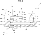
- FIG. 3 is a side view showing the inside of a second arm of the horizontal articulated robot shown in FIG. 1 .
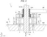
- FIG. 4 is an enlarged sectional view of a region surrounded by a broken line shown in FIG. 3 .
- FIG. 5 is an A-A line sectional view in FIG. 4 .
- an x axis, a y axis, and a z axis are shown as three axes orthogonal to one another.
- a direction parallel to the x axis is referred to as "x-axis direction” as well
- a direction parallel to the y axis is referred to as "y-axis direction” as well
- a direction parallel to the z axis is referred to as "z-axis direction" as well.
- a distal end side of arrows shown in the figures is referred to as “+ (plus) " and a proximal end side of the arrows is referred to as “- (minus) ".
- a direction parallel to a +x-axis direction is referred to as "+x-axis direction” as well.
- a direction parallel to a -x-axis direction is referred to as "-x-axis direction” as well.
- a direction parallel to a +y-axis direction is referred to as "+y-axis direction” as well.
- a direction parallel to a -y-axis direction is referred to as "-y-axis direction” as well.
- a direction parallel to a +z-axis direction is referred to as "+z-axis direction” as well.
- a direction parallel to a -z-axis direction is referred to as “-z-axis direction” as well.
- a direction around the z axis and a direction around an axis parallel to the z axis are referred to as "u-axis direction” as well.
- the +z-axis direction that is, the upper side in FIG. 1 is referred to as “upper” as well and the -z-axis direction, that is, the lower side in FIG. 1 is referred to as “lower” as well.
- a base 21 side in FIG. 1 is referred to as "proximal end” and the opposite side of the base 21 side, that is, an end effector 7 side is referred to as "distal end”.
- the z-axis direction that is, the up-down direction in FIG. 1 is represented as “vertical direction”.
- the x-axis direction and the y-axis direction, that is, the left-right direction is represented as "horizontal direction”.
- a robot system 100 shown in FIGS. 1 and 2 is, for example, an apparatus used in work such as holding, conveyance, assembly, and inspection of work (objects) such as electronic components and electronic devices.
- the robot system 100 includes a control device 1, a robot 2, the end effector 7, a display device 41, and an input device 42.
- control device 1 is disposed on the outer side of the robot 2 .
- control device 1 may be incorporated in the robot 2.
- the robot 2 and the control device 1 are electrically coupled (hereinafter simply referred to as "coupled” as well) by a cable 200.
- the cable 200 may be omitted and the robot 2 and the control device 1 may perform communication in a wireless scheme.
- the robot 2 and the control device 1 may be coupled by wired communication or may be coupled by wireless communication.
- the robot 2 is a horizontal articulated robot, that is, a SCARA robot.
- the robot 2 includes the base 21, a first arm 22, a second arm 23, a third arm 24, which is a work head, a ball screw nut 243, which is a supporting section that supports the third arm 24, and a force detecting section 5.
- the robot arm 20 is configured by the first arm 22, the second arm 23, the third arm 24, and the like.
- the robot 2 includes a driving unit 25 configured to rotate the first arm 22 with respect to the base 21, a driving unit 26 configured to rotate the second arm 23 with respect to the first arm 22, a u-driving unit 27 configured to rotate a shaft 241 of the third arm 24 with respect to the second arm 23, a z-driving unit 28 configured to move the shaft 241 in the z-axis direction with respect to the second arm 23, and an angular velocity sensor 29.
- the driving unit 25 is incorporated in a housing 220 of the first arm 22.
- the driving unit 25 includes a motor 251 configured to generate a driving force, a speed reducer 252 configured to reduce the driving force of the motor 251, and a position sensor 253 configured to detect a rotation angle of a rotation axis of the motor 251 or the speed reducer 252.
- the driving unit 26 is incorporated in a housing 230 of the second arm 23.
- the driving unit 26 includes a motor 261 configured to generate a driving force, a speed reducer 262 configured to reduce the driving force of the motor 261, and a position sensor 263 configured to detect a rotation angle of a rotation axis of the motor 261 or the speed reducer 262.
- the u-driving unit 27 is incorporated in the housing 230 of the second arm 23.
- the u-driving unit 27 includes a motor 271 configured to generate a driving force, a speed reducer 272 configured to reduce the driving force of the motor 271, and a position sensor 273 configured to detect a rotation angle of a rotation axis of the motor 271 or the speed reducer 272.
- the z-driving unit 28 is incorporated in the housing 230 of the second arm 23.
- the z-driving unit 28 includes a motor 281 configured to generate a driving force, a speed reducer 282 configured to reduce the driving force of the motor 281, and a position sensor 283 configured to detect a rotation angle of a rotation axis of the motor 281 or the speed reducer 282.
- a servomotor such as an AC servomotor or a DC servomotor can be used.
- the position sensor 253, the position sensor 263, the position sensor 273, and the position sensor 283 can be, for example, angle sensors.
- the driving unit 25, the driving unit 26, the u-driving unit 27, and the z-driving unit 28 are respectively coupled to not-shown motor drivers corresponding thereto and are controlled by a robot control section 11 of the control device 1 via the motor drivers.
- the speed reducers may be omitted.
- the angular velocity sensor 29 is incorporated in the second arm 23. Accordingly, the angular velocity sensor 29 can detect angular velocity of the second arm 23.
- the control device 1 controls the robot 2 based on information concerning the detected angular velocity.
- the angular velocity sensor 29 is set further on the -y-axis side, that is, a far side of the base 21 than the driving units 26 to 28.
- the base 21 is fixed to, for example, a not-shown floor surface by bolts or the like.
- the first arm 22 is coupled to the upper end portion of the base 21.
- the first arm 22 is rotatable, with respect to the base 21, around a first axis 01 extending along the vertical direction.
- the driving unit 25, which rotates the first arm 22 is driven, the first arm 22 rotates within a horizontal plane around the first axis 01 with respect to the base 21.
- a rotation amount of the first arm 22 with respect to the base 21 can be detected by the position sensor 253.
- the second arm 23 is coupled to the distal end portion of the first arm 22.
- the second arm 23 is rotatable, with respect to the first arm 22, around a second axis 02 extending along the vertical direction.
- the axial direction of the first axis 01 and the axial direction of the second axis 02 are the same.
- the second axis 02 is parallel to the first axis 01.
- the second arm 23 includes the housing 230 including a bottom plate 231, a top plate 232, and a sidewall 233 that couples the bottom plate 231 and the top plate 232.
- the driving unit 26, the u-driving unit 27, the z-driving unit 28, and the angular velocity sensor 29 are disposed in this order from the +y-axis side on the inside of the housing 230, that is, on the bottom plate 231.
- the housing 230 includes an inclined section 234 located between the top plate 232 and the sidewall 233.
- the inclined section 234 is provided on the -y-axis side of the top plate 232.
- the inclined section 234 is provided to be inclined with respect to the z-axis.
- the third arm 24 is set at the distal end portion of the second arm 23.
- the third arm 24 includes the shaft 241 and a rotation supporting member 242 configured to rotatably support the shaft 241.
- the shaft 241 is rotatable, with respect to the second arm 23, around a third axis 03 extending along the vertical direction and movable (elevatable) in the up-down direction.
- the shaft 241 is a third arm of the robot arm 20 and is an arm at the most distal end of the robot arm 20.
- the ball screw nut 243 and a spline nut 244 are set halfway in the longitudinal direction of the shaft 241.
- the shaft 241 is supported by the ball screw nut 243 and the spline nut 244.
- the ball screw nut 243 and the spline nut 244 are disposed to be separated from the +z-axis side in this order.
- the ball screw nut 243 includes an inner ring 243A and an outer ring 243B concentrically disposed on the outer circumference side of the inner ring 243A.
- a not-shown plurality of balls are disposed between the inner ring 243A and the outer ring 243B.
- the inner ring 243A and the outer ring 243B rotate relatively to each other according to movement of the balls.
- the inner ring 243A includes a portion exposed from the outer ring 243B. Abelt 284 explained below is wound around the exposed portion.
- the shaft 241 is inserted through the inside of the inner ring 243A. As explained below, the inner ring 243A supports the shaft 241 movably along the z-axis direction.
- the outer ring 243B is fixed to a base section 230A explained below.
- the spline nut 244 includes an inner ring 244A and an outer ring 244B concentrically disposed on the outer circumference side of the inner ring 244A.
- a not-shown plurality of balls are disposed between the inner ring 244A and the outer ring 244B.
- the inner ring 244A and the outer ring 244B rotate relatively to each other according to movement of the balls.
- the inner ring 244A includes a portion exposed from the outer ring 244B. Abelt 274 explained below is wound around the exposed portion.
- the shaft 241 is inserted through the inside of the inner ring 244A.
- the inner ring 244A supports the shaft 241 rotatably around the z axis, that is, in the u-axis direction.
- the outer ring 244B is fixed to a recess 230C of the base section 230A explained below.
- the rotation supporting member 242 is set on the -z-axis side of the spline nut 244.
- the rotation supporting member 242 includes an outer cylinder 245 and a rotating body 246 provided on the inner side of the outer cylinder 245.
- the outer cylinder 245 is fixed to the bottom plate 231 in the housing 230 of the second arm 23.
- the rotating body 246 is fixed to the shaft 241 but is supported by the outer cylinder 245 rotatably around the z axis together with the shaft 241.
- the shaft 241 When the u-driving unit 27, which rotates the shaft 241, is driven, the shaft 241 normally and reversely rotates, that is, rotates around the z axis. A rotation amount of the shaft 241 with respect to the second arm 23 can be detected by the position sensor 273.
- the shaft 241 moves in the up-down direction, that is, the z-axis direction.
- a movement amount in the z-axis direction of the shaft 241 with respect to the second arm 23 can be detected by the position sensor 283.
- end effectors are detachably coupled to the distal end portion of the shaft 241.
- the end effectors are not particularly limited. Examples of the end effectors include an end effector that grips a conveyed object, an end effector that machines work, and an end effector used for inspection.
- the end effector 7 is detachably coupled to the distal end portion of the shaft 241. The end effector 7 is explained in detail below.
- the end effector 7 is not a component of the robot 2. However, a part of or the entire end effector 7 may be a component of the robot 2. In this embodiment, the end effector 7 is not a component of the robot arm 20. However, a part of or the entire end effector 7 may be a component of the robot arm 20.
- the end effector 7 includes an attachment section 71 attached to the shaft 241, a motor 72 provided in the attachment section 71, and a limit gauge for screw 3 detachably concentrically attached to a rotation axis of the motor 72.
- the end effector 7 is detachably coupled to the distal end portion of the shaft 241.
- the center axis of the shaft 241, that is, the third axis 03 coincides with a rotation axis of the motor 72, and the center axis of the limit gauge for screw 3. In other words, when viewed from the axial direction of the third axis 03, the third axis 03, the motor 72, and the limit gauge for screw 3 overlap.
- the limit gauge for screw 3 is an example of a screw gauge.
- the limit gauge for screw 3 includes a columnar gripping section 31, a go-side gauge 32 that is provided at one end portion of the gripping section 31 and on which a male screw is formed and a stop-side gauge 33 that is provided on the other end portion of the gripping section 31 and on which a male screw is formed.
- the end portion of the gripping section 31 where the stop-side gauge 33 is provided is attached to the rotation axis of the motor 72 and the go-side gauge 32 is disposed on the distal end side of the limit gauge for screw 3.
- the stop-side gauge 33 is used, the end portion of the gripping section 31 where the go-side gauge 32 is provided is attached to the rotation axis of the motor 72 and the stop-side gauge 33 is disposed on the distal end side of the limit gauge for screw 3.
- the motor 72 is not particularly limited.
- a servomotor such as an AC servomotor or a DC servomotor or a stepping motor is used as the motor 72.
- the end effector 7 includes a not-shown angle sensor configured to detect a rotation angle of the rotation axis of the motor 72.
- the rotation angle of the rotation axis of the motor 72 can be detected by the angle sensor.
- the force detecting section 5 is configured by, for example, a force sensor that detects force applied to the third arm 24.
- the configuration of the force detecting section 5 is explained in detail below.
- the limit gauge for screw 3 is not limited to such a configuration.
- the limit gauge for screw 3 may be configured to interchange and use a limit gauge for screw including only a go-side gauge and a limit gauge for screw including only a stop-side gauge.
- the end effector 7 is detachably attachable to the robot arm 20.
- the end effector 7 may be undetachable from the robot arm 20.
- the control device 1 includes the robot control section 11, a motor control section 12 (an end-effector control section), a display control section 13, a storing section 14, a receiving section 15, and a determining section 16.
- the control device 1 respectively controls driving of the sections of the robot system 100 such as the robot 2, the motor 72 of the end effector 7, and the display device 41.
- the control device 1 is configured to be communicable respectively among the robot control section 11, the motor control section 12, the display control section 13, the storing section 14, the receiving section 15, and the determining section 16.
- the robot control section 11, the motor control section 12, the display control section 13, the storing section 14, the receiving section 15, and the determining section 16 are coupled to one another by wired or wireless communication.
- the robot 2, the display device 41, the input device 42, and the end effector 7 are respectively coupled to the control device 1 by wired or wireless communication.
- the robot control section 11 controls driving of the robot 2, that is, driving of the robot arm 20 and the like.
- the robot control section 11 is a computer in which programs such as an OS are installed.
- the robot control section 11 includes, for example, a CPU functioning as a processor, a RAM, and a ROM in which programs are stored.
- the function of the robot control section 11 can be realized by, for example, executing various programs with the CPU.
- the motor control section 12 controls driving of the motor 72.
- the motor control section 12 is a computer in which programs such as an OS are installed.
- the motor control section 12 includes, for example, a CPU functioning as a processor, a RAM, and a ROM in which programs are stored.
- the function of the motor control section 12 can be realized by, for example, executing various programs with the CPU.
- the display control section 13 has a function of causing the display device 41 to display various screens such as a window, characters, and the like. In other words, the display control section 13 controls driving of the display device 41.
- the function of the display control section 13 can be realized by, for example, a GPU.
- the storing section 14 has a function of storing various kinds of information (including data and programs).
- the storing section 14 stores a control program and the like.
- the function of the storing section 14 can be realized by a so-called external storage device (not shown in FIG. 2 ) such as a ROM.
- the receiving section 15 has a function of receiving an input from the input device 42.
- the function of the receiving section 15 can be realized by, for example, an interface circuit.
- the receiving section 15 has a function of an input detecting section that detects, for example, contact of a finger of a user with the touch panel.
- the display device 41 includes a not-shown monitor configured by, for example, a liquid crystal display or an EL display.
- the display device 41 has a function of displaying various images including various screens such as a window, characters, and the like.
- the input device 42 is configured by, for example, a mouse and a keyboard. Therefore, the user can give instructions for various kinds of processing and the like to the control device 1 by operating the input device 42.
- the user can give instructions to the control device 1 with operation for clicking, with the mouse of the input device 42, various screens such as a window displayed on the display device 41 and operation for inputting characters, numbers, and the like with the keyboard of the input devoice 42.
- a display input device including both of the display device 41 and the input device 42 may be provided instead of the display device 41 and the input device 42.
- a touch panel such as an electrostatic touch panel or a pressure-sensitive touch panel can be used.
- the input device 42 may be configured to recognize sound such as voice.
- the u-driving unit 27 that rotates the third arm 24 around the z axis, the z-driving unit 28 that moves the third arm 24 in the z-axis direction, the belt 274, and the belt 284 are provided in the housing 230 of the second arm 23.
- the housing 230 of the second arm 23 includes the base section 230A and a cover member 230B configured to cover the +z-axis side of the base section 230A.
- the base section 230A is a rigid body and is made of, for example, a metal material or any one of various hard resin materials.
- the base section 230A includes the recess 230C in which the u-driving unit 27 is disposed. A part on the -z-axis side of the recess 230C is opened to the -z-axis side.
- the rotation supporting member 242 is embedded in this opened portion.
- the shaft 241 is inserted through the recess 230C. Since the base section 230A configures the second arm 23, in the following explanation, the second arm 23 is referred to as base section 230A as well.
- the u-driving unit 27 includes a pulley 275 in addition to the motor 271, the speed reducer 272, and the position sensor 273.
- the position sensor 273, the motor 271, the speed reducer 272, and the pulley 275 are disposed from the +z-axis side in this order and fixed to the bottom of the recess 230C.
- the pulley 275 is fixed to a core of the speed reducer 272. A rotation force of the motor 271 is reduced by the speed reducer 272 and transmitted to the pulley 275.
- the pulley 275 is coupled to, by the belt 274, the inner ring 244A of the spline nut 244 provided in the shaft 241.
- the belt 274 is an endless belt wound around the pulley 275 and the inner ring 244A.
- the belt 274 includes not-shown teeth on the inner side of the belt 274, that is, the pulley 275 and inner ring 244A side.
- the teeth of the belt 274 are respectively meshed with not-shown teeth of the pulley 275 and the exposed portion of the inner ring 244A.
- the rotation force of the motor 271 is transmitted to the belt 274 via the speed reducer 272 and the pulley 275 and the belt 274 rotates.
- the rotation force is transmitted to the shaft 241 via the spline nut 244.
- the rotation force is transmitted to the shaft 241 via the inner circumferential portion of the inner ring 244A and a not-shown spline groove of the shaft 241.
- the shaft 241 can move in the u-axis direction, that is, rotate.
- the z-driving unit 28 includes a pulley 285 in addition to the motor 281, the speed reducer 282, and the position sensor 283.
- the position sensor 283, the motor 281, the pulley 285, and the speed reducer 282 are disposed from the +z-axis side in this order.
- the pulley 285 is fixed to a core of the speed reducer 282.
- a rotation force of the motor 281 is reduced by the speed reducer 282 and transmitted to the pulley 285.
- the speed reducer 282 is fixed to the base section 230A.
- the pulley 285 is coupled to, by the belt 284, the exposed portion of the inner ring 243A of the ball screw nut 243 provided in the shaft 241.
- the belt 284 is an endless belt wound around the pulley 285 and the inner ring 243A.
- the belt 284 includes not-shown teeth on the inner side of the belt 284, that is, the pulley 285 and inner ring 243A side.
- the teeth of the belt 284 are respectively meshed with not-shown teeth of the pulley 285 and the inner ring 243A.
- the rotation force of the motor 281 is transmitted to the belt 284 via the speed reducer 282 and the pulley 285 and the belt 284 rotates.
- the rotation force is transmitted to the shaft 241 via the inner ring 243A of the ball screw nut 243.
- the direction of the rotation force is changed by the inner circumferential portion of the inner ring 243A and a ball screw groove of the shaft 241.
- the shaft 241 can move in the z-axis direction, that is, move up and down.
- the force detecting section 5 is explained.
- the force detecting section 5 is a sensor that detects the force applied to the third arm 24 as explained above.
- the force detecting section 5 is provided between the ball screw nut 243 and the base section 230A and fixed to and held by the ball screw nut 243 and the base section 230A.
- the force detecting section 5 includes a first plate 51, a second plate 52, a tubular section 53 disposed between the first plate 51 and the second plate 52, and a plurality of, in this embodiment, two elements 54. The two elements 54 are held between the first plate 51 and the second plate 52. Most of the weight of the force detecting section 5 is born by the base section 230A.
- the force detecting section 5 includes the first plate 51, the second plate 52, and the plurality of, in this embodiment, two elements 54 held by the first plate 51 and the second plate 52. Consequently, as explained below, the elements 54 can detect force applied to the shaft 241.
- the first plate 51 is formed in a disk shape.
- the first plate 51 includes, in the center thereof, a through-hole 511 through which the shaft 241 is inserted.
- the first plate 51 is fixed to, via fixing members 8 such as screws or machine screws, the -z-axis side of the outer ring 243B of the ball screw nut 243.
- the second plate 52 is formed in a disk shape.
- the second plate 52 includes, in the center thereof, a through-hole 521 through which the shaft 241 is inserted.
- the second plate 52 is fixed to, via fixing members 9 such as screws or machine screws, the +z-axis side of the base section 230A.
- the first plate 51 is fixed to the ball screw nut 243, which is the supporting section.
- the second plate 52 is fixed to the second arm 23. Consequently, as explained below, force applied to the shaft 241 is transmitted to the elements 54 via the shaft 241, the inner ring 243A, the outer ring 243B, and the first plate 51.
- the first plate 51 and the second plate 52 include the through-holes 511 and 521 through which the third arm 24 is inserted. Consequently, the third arm 24 can be inserted through the force detecting section 5.
- the force detecting section 5 can be disposed coaxially with the third arm 24.
- the force detecting section 5 is disposed coaxially with the third arm 24, that is, when viewed from the axial direction of the third axis 03, the force detecting section 5 is disposed in a position overlapping the ball screw nut 243, which is the supporting section. Consequently, force applied to the third arm 24 can be more directly detected.
- the tubular section 53 is formed in a cylindrical shape and has a function of protecting the elements 54.
- the elements 54 are disposed to be opposed to each other via the shaft 241.
- the third axis 03 is present between the plurality of elements 54. Consequently, forces applied to the elements 54 become uniform as much as possible. The forces can be accurately detected.
- an element that is configured by a piezoelectric body such as quartz and outputs electric charges when receiving an external force can be used.
- the control device 1 can convert the electric charges into the received external force according to an amount of the electric charges.
- a piezoelectric body is capable of adjusting, according to a setting direction of the piezoelectric body, a direction in which the electric charges are generated when the external force is received.
- the elements 54 can detect, as shown in FIG. 5 , force Fz, which is a component in the vertical direction, and force Fu around the z axis, that is, in the u-axis direction.
- the force detecting section 5 detects the force Fz in the axial direction of the third axis 03. Consequently, it is possible to more accurately perform work for moving the shaft 241 along the z-axis direction.
- the force detecting section 5 is provided between the second arm 23 (the base section 230A) and the ball screw nut 243, which is the supporting section that supports the third arm 24. Accordingly, when external force is applied to the shaft 241 of the third arm 24, the external force is transmitted to the elements 54 via the shaft 241, the inner ring 243A, the outer ring 243B, and the first plate 51. Consequently, the force detecting section 5 can detect the force applied to the shaft 241.
- a force detecting section is provided at the distal end portion of an arm equivalent to the third arm 24. The arm is configured to bear substantially the entire weight of the force detecting section. Accordingly, substantial weight capacity of the arm decreases by the weight of the force detecting section.
- the base section 230A is configured to bear the weight of the force detecting section 5 itself, it is possible to prevent or suppress the weight capacity from decreasing because of the weight of the force detecting section as in the past. As a result, it is possible to sufficiently secure the weight capacity of the third arm 24.
- the second arm 23 includes the u-driving unit 27 and the z-driving unit 28, which are the driving units that drive the third arm 24, and the base section 230A that supports the u-driving unit 27 and the z-driving unit 28.
- the force detecting section 5 is provided between the base section 230A and the ball screw nut 243, which is the supporting section. Consequently, the base section 230A can bear the weight of the force detecting section 5.
- the third arm 24 can be stably driven.
- the supporting section which supports the shaft 241
- the ball screw nut 243 which is a bearing member fixed to the third arm 24
- the external force applied to the shaft 241 is more directly transmitted to the force detecting section 5.
- the robot 2 includes the base 21, the first arm 22 coupled to the base 21 and configured to turn around the first axis 01, the second arm 23 coupled to the first arm 22 and configured to turn around the second axis 02 parallel to the first axis 01, the third arm 24 coupled to the second arm 23 and configured to turn around the third axis 03 parallel to the first axis 01 and move along the third axis 03, the ball screw nut 243, which is the supporting section provided in the second arm 23 and configured to support the third arm 24, and the force detecting section 5 provided between the second arm 23 and the ball screw nut 243 and configured to detect force applied to the third arm 24. Consequently, the force detecting section 5 can detect the force applied to the third arm 24.
- the force detecting section is provided in the third arm and the substantial weight capacity of the third arm decreases by the weight of the force detecting section.
- the second arm 23 is configured to bear the weight of the force detecting section 5 itself, it is possible to prevent or suppress a deficiency caused by the configuration in the past. In other words, according to the present disclosure, it is possible to sufficiently secure the weight capacity of the third arm 24.
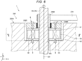
- a second embodiment of the horizontal articulated robot according to the present disclosure is explained with reference to FIGS. 6 and 7 . Differences from the first embodiment are mainly explained. Explanation of similarities to the first embodiment is omitted.
- the force detecting section 5 between the ball screw nut 243 and the base section 230A explained in the first embodiment is omitted.
- the force detecting section 5 is disposed in a position explained below.
- the force detecting section 5 is set and fixed on the bottom of the recess 230C of the base section 230A.
- the spline nut 244 is set and fixed on the +z-axis side of the force detecting section 5.
- the force detecting section 5 is set and held between the bottom of the recess 230C of the base section 230A and the spline nut 244. Most of the weight of the force detecting section 5 is born by the base section 230A of the second arm 23.
- the first plate 51 is fixed to the -z-axis side of the outer ring 244B of the spline nut 244 via the fixing members 8 such as screws or machine screws.
- the second plate 52 is fixed to the +z-axis side of the bottom of the recess 230C of the base section 230A via the fixing members 9 such as screws or machine screws.
- each element 54 is set at equal intervals along the circumferential direction of the shaft 241.
- two pairs of the elements 54 provided via the third axis 03 are provided.
- the elements 54 can detect the force Fz, which is a component in the vertical direction, and the force Fu around the z axis, that is, in the u-axis direction.
- the force detecting section 5 is provided and held between the spline nut 244, which is the supporting section that supports the third arm 24, and the second arm 23. Consequently, the force detecting section 5 can detect force applied to the third arm 24. As in the first embodiment, it is possible to sufficiently secure the weight capacity of the third arm 24.
- the horizontal articulated robot according to the present disclosure is explained above based on the embodiments shown in the figures. However, the present disclosure is not limited to this .
- the components of the sections can be replaced with any components having the same functions. Any other components may be added.
- the number of rotation axes of the robot arm is three.
- the number of rotation axes of the robot arm is not limited to this.
- the number of rotation axes of the robot arm may be, for example, two or four or more.
- the number of arms is three.
- the number of arms is not limited to this.
- the number of arms may be, for example, two or four or more.
Landscapes
- Engineering & Computer Science (AREA)
- Robotics (AREA)
- Mechanical Engineering (AREA)
- Human Computer Interaction (AREA)
- Manipulator (AREA)
Abstract
Description
- The present application is based on, and claims priority from
JP Application Serial Number 2019-066088, filed March 29, 2019 - The present disclosure relates to a horizontal articulated robot.
- In recent years, in factories, according to a sharp rise in personal expenses and labor shortage, automation of work that has been manually performed has been accelerated by various robots and peripheral apparatuses of the robots. In simple conveying and screwing processes, for example, a horizontal articulated robot, that is, a SCARA robot described in
JP A-4-256590 - The SCARA robot described in
Patent Literature 1 includes a first arm that rotates around a first axis, a second arm that rotates around a second axis, and a third arm that rotates around a third axis and moves in a third axial direction. Concerning driving of the third arm, operations of the rotation around the third axis and the movement in the third axial direction are realized using a ball screw spline. A force sensor is set at the distal end of the third arm. Driving of the robot is controlled based on force detected by the force sensor to perform various kinds of work. - However, in the SCARA robot described in
Patent Literature 1, since the weight of the force sensor is included in weight capacity, substantial weight capacity decreases by the weight of the force sensor. Therefore, the weight capacity cannot be sufficiently secured depending on the weight of the force sensor. - An advantage of some aspects of the present disclosure is to solve at least a part of the problems described above and the present disclosure can be implemented by the following application example.
- A horizontal articulated robot according to an application example includes: a base; a first arm coupled to the base and configured to turn around a first axis; a second arm coupled to the first arm and configured to turn around a second axis parallel to the first axis; a third arm coupled to the second arm and configured to turn around a third axis parallel to the first axis and move along the third axis; a supporting section provided in the second arm and configured to support the third arm; and a force detecting section provided between the second arm and the supporting section and configured to detect force applied to the third arm.
-
-
FIG. 1 is a side view showing a first embodiment of a horizontal articulated robot according to the present disclosure. -
FIG. 2 is a block diagram of the robot system shown inFIG. 1 . -
FIG. 3 is a side view showing the inside of a second arm of the horizontal articulated robot shown inFIG. 1 . -
FIG. 4 is an enlarged sectional view of a region surrounded by a broken line shown inFIG. 3 . -
FIG. 5 is an A-A line sectional view inFIG. 4 . -
FIG. 6 is a side view showing a second embodiment of the horizontal articulated robot according to the present disclosure. -
FIG. 7 is a B-B line sectional view inFIG. 6 . - A horizontal articulated robot according to the present disclosure is explained in detail below based on preferred embodiments shown in the accompanying drawings.
-
FIG. 1 is a side view showing a first embodiment of the horizontal articulated robot according to the present disclosure.FIG. 2 is a block diagram of the robot system shown inFIG. 1 .FIG. 3 is a side view showing the inside of a second arm of the horizontal articulated robot shown inFIG. 1 .FIG. 4 is an enlarged sectional view of a region surrounded by a broken line shown inFIG. 3 .FIG. 5 is an A-A line sectional view inFIG. 4 . - In
FIGS. 1 to 4 , for convenience of explanation, an x axis, a y axis, and a z axis are shown as three axes orthogonal to one another. In the following explanation, a direction parallel to the x axis is referred to as "x-axis direction" as well, a direction parallel to the y axis is referred to as "y-axis direction" as well, and a direction parallel to the z axis is referred to as "z-axis direction" as well. Further, in the following explanation, a distal end side of arrows shown in the figures is referred to as "+ (plus) " and a proximal end side of the arrows is referred to as "- (minus) ". A direction parallel to a +x-axis direction is referred to as "+x-axis direction" as well. A direction parallel to a -x-axis direction is referred to as "-x-axis direction" as well. A direction parallel to a +y-axis direction is referred to as "+y-axis direction" as well. A direction parallel to a -y-axis direction is referred to as "-y-axis direction" as well. A direction parallel to a +z-axis direction is referred to as "+z-axis direction" as well. A direction parallel to a -z-axis direction is referred to as "-z-axis direction" as well. A direction around the z axis and a direction around an axis parallel to the z axis are referred to as "u-axis direction" as well. - Further, in the following explanation, for convenience of explanation, the +z-axis direction, that is, the upper side in
FIG. 1 is referred to as "upper" as well and the -z-axis direction, that is, the lower side inFIG. 1 is referred to as "lower" as well. About arobot arm 20, abase 21 side inFIG. 1 is referred to as "proximal end" and the opposite side of thebase 21 side, that is, anend effector 7 side is referred to as "distal end". The z-axis direction, that is, the up-down direction inFIG. 1 is represented as "vertical direction". The x-axis direction and the y-axis direction, that is, the left-right direction is represented as "horizontal direction". - A
robot system 100 shown inFIGS. 1 and2 is, for example, an apparatus used in work such as holding, conveyance, assembly, and inspection of work (objects) such as electronic components and electronic devices. Therobot system 100 includes acontrol device 1, arobot 2, theend effector 7, adisplay device 41, and aninput device 42. - In a configuration shown in
FIGS. 1 and2 , thecontrol device 1 is disposed on the outer side of therobot 2 . However, not only this, but thecontrol device 1 may be incorporated in therobot 2. - In the configuration shown in
FIGS. 1 and2 , therobot 2 and thecontrol device 1 are electrically coupled (hereinafter simply referred to as "coupled" as well) by acable 200. However, not only this, but, thecable 200 may be omitted and therobot 2 and thecontrol device 1 may perform communication in a wireless scheme. In other words, therobot 2 and thecontrol device 1 may be coupled by wired communication or may be coupled by wireless communication. - The
robot 2 is a horizontal articulated robot, that is, a SCARA robot. - As shown in
FIGS. 1 to 4 , therobot 2 includes thebase 21, afirst arm 22, asecond arm 23, athird arm 24, which is a work head, aball screw nut 243, which is a supporting section that supports thethird arm 24, and aforce detecting section 5. Therobot arm 20 is configured by thefirst arm 22, thesecond arm 23, thethird arm 24, and the like. - The
robot 2 includes adriving unit 25 configured to rotate thefirst arm 22 with respect to thebase 21, adriving unit 26 configured to rotate thesecond arm 23 with respect to thefirst arm 22, au-driving unit 27 configured to rotate ashaft 241 of thethird arm 24 with respect to thesecond arm 23, a z-drivingunit 28 configured to move theshaft 241 in the z-axis direction with respect to thesecond arm 23, and anangular velocity sensor 29. - As shown in
FIGS. 1 and2 , thedriving unit 25 is incorporated in ahousing 220 of thefirst arm 22. Thedriving unit 25 includes amotor 251 configured to generate a driving force, aspeed reducer 252 configured to reduce the driving force of themotor 251, and aposition sensor 253 configured to detect a rotation angle of a rotation axis of themotor 251 or thespeed reducer 252. - The
driving unit 26 is incorporated in ahousing 230 of thesecond arm 23. Thedriving unit 26 includes amotor 261 configured to generate a driving force, aspeed reducer 262 configured to reduce the driving force of themotor 261, and aposition sensor 263 configured to detect a rotation angle of a rotation axis of themotor 261 or thespeed reducer 262. - The
u-driving unit 27 is incorporated in thehousing 230 of thesecond arm 23. The u-drivingunit 27 includes amotor 271 configured to generate a driving force, aspeed reducer 272 configured to reduce the driving force of themotor 271, and aposition sensor 273 configured to detect a rotation angle of a rotation axis of themotor 271 or thespeed reducer 272. - The z-driving
unit 28 is incorporated in thehousing 230 of thesecond arm 23. The z-drivingunit 28 includes amotor 281 configured to generate a driving force, aspeed reducer 282 configured to reduce the driving force of themotor 281, and aposition sensor 283 configured to detect a rotation angle of a rotation axis of themotor 281 or thespeed reducer 282. - As the
motor 251, themotor 261, themotor 271, and themotor 281, for example, a servomotor such as an AC servomotor or a DC servomotor can be used. - As the
speed reducer 252, thespeed reducer 262, thespeed reducer 272, and thespeed reducer 282, for example, a speed reducer of a planetary gear type or a wave motion gear device can be used. Theposition sensor 253, theposition sensor 263, theposition sensor 273, and theposition sensor 283 can be, for example, angle sensors. - The driving
unit 25, the drivingunit 26, theu-driving unit 27, and the z-drivingunit 28 are respectively coupled to not-shown motor drivers corresponding thereto and are controlled by arobot control section 11 of thecontrol device 1 via the motor drivers. The speed reducers may be omitted. - The
angular velocity sensor 29 is incorporated in thesecond arm 23. Accordingly, theangular velocity sensor 29 can detect angular velocity of thesecond arm 23. Thecontrol device 1 controls therobot 2 based on information concerning the detected angular velocity. Theangular velocity sensor 29 is set further on the -y-axis side, that is, a far side of the base 21 than the drivingunits 26 to 28. - The
base 21 is fixed to, for example, a not-shown floor surface by bolts or the like. Thefirst arm 22 is coupled to the upper end portion of thebase 21. Thefirst arm 22 is rotatable, with respect to thebase 21, around afirst axis 01 extending along the vertical direction. When the drivingunit 25, which rotates thefirst arm 22, is driven, thefirst arm 22 rotates within a horizontal plane around thefirst axis 01 with respect to thebase 21. A rotation amount of thefirst arm 22 with respect to the base 21 can be detected by theposition sensor 253. - The
second arm 23 is coupled to the distal end portion of thefirst arm 22. Thesecond arm 23 is rotatable, with respect to thefirst arm 22, around asecond axis 02 extending along the vertical direction. The axial direction of thefirst axis 01 and the axial direction of thesecond axis 02 are the same. In other words, thesecond axis 02 is parallel to thefirst axis 01. When the drivingunit 26, which rotates thesecond arm 23, is driven, thesecond arm 23 rotates within a horizontal plane around thesecond axis 02 with respect to thefirst arm 22. Driving, specifically, a rotation amount of thesecond arm 23 with respect to thefirst arm 22 can be detected by theposition sensor 263. - The
second arm 23 includes thehousing 230 including abottom plate 231, atop plate 232, and asidewall 233 that couples thebottom plate 231 and thetop plate 232. The drivingunit 26, theu-driving unit 27, the z-drivingunit 28, and theangular velocity sensor 29 are disposed in this order from the +y-axis side on the inside of thehousing 230, that is, on thebottom plate 231. - The
housing 230 includes aninclined section 234 located between thetop plate 232 and thesidewall 233. Theinclined section 234 is provided on the -y-axis side of thetop plate 232. Theinclined section 234 is provided to be inclined with respect to the z-axis. - As shown in
FIG. 3 , thethird arm 24 is set at the distal end portion of thesecond arm 23. Thethird arm 24 includes theshaft 241 and arotation supporting member 242 configured to rotatably support theshaft 241. - The
shaft 241 is rotatable, with respect to thesecond arm 23, around athird axis 03 extending along the vertical direction and movable (elevatable) in the up-down direction. Theshaft 241 is a third arm of therobot arm 20 and is an arm at the most distal end of therobot arm 20. - The
ball screw nut 243 and aspline nut 244 are set halfway in the longitudinal direction of theshaft 241. Theshaft 241 is supported by theball screw nut 243 and thespline nut 244. Theball screw nut 243 and thespline nut 244 are disposed to be separated from the +z-axis side in this order. - The
ball screw nut 243 includes aninner ring 243A and anouter ring 243B concentrically disposed on the outer circumference side of theinner ring 243A. A not-shown plurality of balls are disposed between theinner ring 243A and theouter ring 243B. Theinner ring 243A and theouter ring 243B rotate relatively to each other according to movement of the balls. - The
inner ring 243A includes a portion exposed from theouter ring 243B.Abelt 284 explained below is wound around the exposed portion. Theshaft 241 is inserted through the inside of theinner ring 243A. As explained below, theinner ring 243A supports theshaft 241 movably along the z-axis direction. Theouter ring 243B is fixed to abase section 230A explained below. - The
spline nut 244 includes aninner ring 244A and anouter ring 244B concentrically disposed on the outer circumference side of theinner ring 244A. A not-shown plurality of balls are disposed between theinner ring 244A and theouter ring 244B. Theinner ring 244A and theouter ring 244B rotate relatively to each other according to movement of the balls. - The
inner ring 244A includes a portion exposed from theouter ring 244B.Abelt 274 explained below is wound around the exposed portion. Theshaft 241 is inserted through the inside of theinner ring 244A. Theinner ring 244A supports theshaft 241 rotatably around the z axis, that is, in the u-axis direction. Theouter ring 244B is fixed to arecess 230C of thebase section 230A explained below. - The
rotation supporting member 242 is set on the -z-axis side of thespline nut 244. Therotation supporting member 242 includes anouter cylinder 245 and arotating body 246 provided on the inner side of theouter cylinder 245. Theouter cylinder 245 is fixed to thebottom plate 231 in thehousing 230 of thesecond arm 23. On the other hand, therotating body 246 is fixed to theshaft 241 but is supported by theouter cylinder 245 rotatably around the z axis together with theshaft 241. - When the
u-driving unit 27, which rotates theshaft 241, is driven, theshaft 241 normally and reversely rotates, that is, rotates around the z axis. A rotation amount of theshaft 241 with respect to thesecond arm 23 can be detected by theposition sensor 273. - When the z-driving
unit 28, which moves theshaft 241 in the z-axis direction, is driven, theshaft 241 moves in the up-down direction, that is, the z-axis direction. A movement amount in the z-axis direction of theshaft 241 with respect to thesecond arm 23 can be detected by theposition sensor 283. - Various end effectors are detachably coupled to the distal end portion of the
shaft 241. The end effectors are not particularly limited. Examples of the end effectors include an end effector that grips a conveyed object, an end effector that machines work, and an end effector used for inspection. In this embodiment, theend effector 7 is detachably coupled to the distal end portion of theshaft 241. Theend effector 7 is explained in detail below. - In this embodiment, the
end effector 7 is not a component of therobot 2. However, a part of or theentire end effector 7 may be a component of therobot 2. In this embodiment, theend effector 7 is not a component of therobot arm 20. However, a part of or theentire end effector 7 may be a component of therobot arm 20. - As shown in
FIG. 1 , theend effector 7 includes anattachment section 71 attached to theshaft 241, amotor 72 provided in theattachment section 71, and a limit gauge forscrew 3 detachably concentrically attached to a rotation axis of themotor 72. Theend effector 7 is detachably coupled to the distal end portion of theshaft 241. The center axis of theshaft 241, that is, thethird axis 03 coincides with a rotation axis of themotor 72, and the center axis of the limit gauge forscrew 3. In other words, when viewed from the axial direction of thethird axis 03, thethird axis 03, themotor 72, and the limit gauge forscrew 3 overlap. - The limit gauge for
screw 3 is an example of a screw gauge. The limit gauge forscrew 3 includes a columnargripping section 31, a go-side gauge 32 that is provided at one end portion of the grippingsection 31 and on which a male screw is formed and a stop-side gauge 33 that is provided on the other end portion of the grippingsection 31 and on which a male screw is formed. In the limit gauge forscrew 3, when the go-side gauge 32 is used, the end portion of the grippingsection 31 where the stop-side gauge 33 is provided is attached to the rotation axis of themotor 72 and the go-side gauge 32 is disposed on the distal end side of the limit gauge forscrew 3. When the stop-side gauge 33 is used, the end portion of the grippingsection 31 where the go-side gauge 32 is provided is attached to the rotation axis of themotor 72 and the stop-side gauge 33 is disposed on the distal end side of the limit gauge forscrew 3. - The
motor 72 is not particularly limited. For example, a servomotor such as an AC servomotor or a DC servomotor or a stepping motor is used as themotor 72. - The
end effector 7 includes a not-shown angle sensor configured to detect a rotation angle of the rotation axis of themotor 72. The rotation angle of the rotation axis of themotor 72 can be detected by the angle sensor. - The
force detecting section 5 is configured by, for example, a force sensor that detects force applied to thethird arm 24. The configuration of theforce detecting section 5 is explained in detail below. - In the
end effector 7, deterioration in rotation accuracy due to backlash can be suppressed compared with when a power transmission mechanism such as a gear or a belt is interposed between the rotation axis of themotor 72 and the limit gauge forscrew 3. - The limit gauge for
screw 3 is not limited to such a configuration. The limit gauge forscrew 3 may be configured to interchange and use a limit gauge for screw including only a go-side gauge and a limit gauge for screw including only a stop-side gauge. - In this embodiment, the
end effector 7 is detachably attachable to therobot arm 20. However, not only this, but, for example, theend effector 7 may be undetachable from therobot arm 20. - As shown in
FIG. 2 , thecontrol device 1 includes therobot control section 11, a motor control section 12 (an end-effector control section), adisplay control section 13, a storingsection 14, a receivingsection 15, and a determiningsection 16. Thecontrol device 1 respectively controls driving of the sections of therobot system 100 such as therobot 2, themotor 72 of theend effector 7, and thedisplay device 41. - The
control device 1 is configured to be communicable respectively among therobot control section 11, themotor control section 12, thedisplay control section 13, the storingsection 14, the receivingsection 15, and the determiningsection 16. In other words, therobot control section 11, themotor control section 12, thedisplay control section 13, the storingsection 14, the receivingsection 15, and the determiningsection 16 are coupled to one another by wired or wireless communication. - The
robot 2, thedisplay device 41, theinput device 42, and theend effector 7 are respectively coupled to thecontrol device 1 by wired or wireless communication. - The
robot control section 11 controls driving of therobot 2, that is, driving of therobot arm 20 and the like. Therobot control section 11 is a computer in which programs such as an OS are installed. Therobot control section 11 includes, for example, a CPU functioning as a processor, a RAM, and a ROM in which programs are stored. The function of therobot control section 11 can be realized by, for example, executing various programs with the CPU. - The
motor control section 12 controls driving of themotor 72. Themotor control section 12 is a computer in which programs such as an OS are installed. Themotor control section 12 includes, for example, a CPU functioning as a processor, a RAM, and a ROM in which programs are stored. The function of themotor control section 12 can be realized by, for example, executing various programs with the CPU. - The
display control section 13 has a function of causing thedisplay device 41 to display various screens such as a window, characters, and the like. In other words, thedisplay control section 13 controls driving of thedisplay device 41. The function of thedisplay control section 13 can be realized by, for example, a GPU. - The storing
section 14 has a function of storing various kinds of information (including data and programs). The storingsection 14 stores a control program and the like. The function of the storingsection 14 can be realized by a so-called external storage device (not shown inFIG. 2 ) such as a ROM. - The receiving
section 15 has a function of receiving an input from theinput device 42. The function of the receivingsection 15 can be realized by, for example, an interface circuit. For example, when a touch panel is used, the receivingsection 15 has a function of an input detecting section that detects, for example, contact of a finger of a user with the touch panel. - The
display device 41 includes a not-shown monitor configured by, for example, a liquid crystal display or an EL display. Thedisplay device 41 has a function of displaying various images including various screens such as a window, characters, and the like. - The
input device 42 is configured by, for example, a mouse and a keyboard. Therefore, the user can give instructions for various kinds of processing and the like to thecontrol device 1 by operating theinput device 42. - Specifically, the user can give instructions to the
control device 1 with operation for clicking, with the mouse of theinput device 42, various screens such as a window displayed on thedisplay device 41 and operation for inputting characters, numbers, and the like with the keyboard of theinput devoice 42. - In this embodiment, a display input device including both of the
display device 41 and theinput device 42 may be provided instead of thedisplay device 41 and theinput device 42. As the display input device, a touch panel such as an electrostatic touch panel or a pressure-sensitive touch panel can be used. Theinput device 42 may be configured to recognize sound such as voice. - The inside of the
second arm 23 is explained. - In the
robot 2, as shown inFIG. 3 , theu-driving unit 27 that rotates thethird arm 24 around the z axis, the z-drivingunit 28 that moves thethird arm 24 in the z-axis direction, thebelt 274, and thebelt 284 are provided in thehousing 230 of thesecond arm 23. - The
housing 230 of thesecond arm 23 includes thebase section 230A and acover member 230B configured to cover the +z-axis side of thebase section 230A. Thebase section 230A is a rigid body and is made of, for example, a metal material or any one of various hard resin materials. Thebase section 230A includes therecess 230C in which theu-driving unit 27 is disposed. A part on the -z-axis side of therecess 230C is opened to the -z-axis side. Therotation supporting member 242 is embedded in this opened portion. Theshaft 241 is inserted through therecess 230C. Since thebase section 230A configures thesecond arm 23, in the following explanation, thesecond arm 23 is referred to asbase section 230A as well. - As shown in
FIG. 3 , theu-driving unit 27 includes apulley 275 in addition to themotor 271, thespeed reducer 272, and theposition sensor 273. Theposition sensor 273, themotor 271, thespeed reducer 272, and thepulley 275 are disposed from the +z-axis side in this order and fixed to the bottom of therecess 230C. Thepulley 275 is fixed to a core of thespeed reducer 272. A rotation force of themotor 271 is reduced by thespeed reducer 272 and transmitted to thepulley 275. - The
pulley 275 is coupled to, by thebelt 274, theinner ring 244A of thespline nut 244 provided in theshaft 241. Thebelt 274 is an endless belt wound around thepulley 275 and theinner ring 244A. Thebelt 274 includes not-shown teeth on the inner side of thebelt 274, that is, thepulley 275 andinner ring 244A side. The teeth of thebelt 274 are respectively meshed with not-shown teeth of thepulley 275 and the exposed portion of theinner ring 244A. - In such a
u-driving unit 27, the rotation force of themotor 271 is transmitted to thebelt 274 via thespeed reducer 272 and thepulley 275 and thebelt 274 rotates. According to the rotation of thebelt 274, the rotation force is transmitted to theshaft 241 via thespline nut 244. The rotation force is transmitted to theshaft 241 via the inner circumferential portion of theinner ring 244A and a not-shown spline groove of theshaft 241. Theshaft 241 can move in the u-axis direction, that is, rotate. - As shown in
FIG. 3 , the z-drivingunit 28 includes apulley 285 in addition to themotor 281, thespeed reducer 282, and theposition sensor 283. Theposition sensor 283, themotor 281, thepulley 285, and thespeed reducer 282 are disposed from the +z-axis side in this order. Thepulley 285 is fixed to a core of thespeed reducer 282. A rotation force of themotor 281 is reduced by thespeed reducer 282 and transmitted to thepulley 285. Thespeed reducer 282 is fixed to thebase section 230A. - The
pulley 285 is coupled to, by thebelt 284, the exposed portion of theinner ring 243A of theball screw nut 243 provided in theshaft 241. Thebelt 284 is an endless belt wound around thepulley 285 and theinner ring 243A. Thebelt 284 includes not-shown teeth on the inner side of thebelt 284, that is, thepulley 285 andinner ring 243A side. The teeth of thebelt 284 are respectively meshed with not-shown teeth of thepulley 285 and theinner ring 243A. - In such a z-driving
unit 28, the rotation force of themotor 281 is transmitted to thebelt 284 via thespeed reducer 282 and thepulley 285 and thebelt 284 rotates. According to the rotation of thebelt 284, the rotation force is transmitted to theshaft 241 via theinner ring 243A of theball screw nut 243. The direction of the rotation force is changed by the inner circumferential portion of theinner ring 243A and a ball screw groove of theshaft 241. Theshaft 241 can move in the z-axis direction, that is, move up and down. - The
force detecting section 5 is explained. - As shown in
FIGS. 3 and4 , theforce detecting section 5 is a sensor that detects the force applied to thethird arm 24 as explained above. In this embodiment, theforce detecting section 5 is provided between theball screw nut 243 and thebase section 230A and fixed to and held by theball screw nut 243 and thebase section 230A. As shown inFIG. 4 , theforce detecting section 5 includes afirst plate 51, asecond plate 52, atubular section 53 disposed between thefirst plate 51 and thesecond plate 52, and a plurality of, in this embodiment, twoelements 54. The twoelements 54 are held between thefirst plate 51 and thesecond plate 52. Most of the weight of theforce detecting section 5 is born by thebase section 230A. - In this way, the
force detecting section 5 includes thefirst plate 51, thesecond plate 52, and the plurality of, in this embodiment, twoelements 54 held by thefirst plate 51 and thesecond plate 52. Consequently, as explained below, theelements 54 can detect force applied to theshaft 241. - The
first plate 51 is formed in a disk shape. Thefirst plate 51 includes, in the center thereof, a through-hole 511 through which theshaft 241 is inserted. Thefirst plate 51 is fixed to, via fixingmembers 8 such as screws or machine screws, the -z-axis side of theouter ring 243B of theball screw nut 243. - The
second plate 52 is formed in a disk shape. Thesecond plate 52 includes, in the center thereof, a through-hole 521 through which theshaft 241 is inserted. Thesecond plate 52 is fixed to, via fixingmembers 9 such as screws or machine screws, the +z-axis side of thebase section 230A. - In this way, the
first plate 51 is fixed to theball screw nut 243, which is the supporting section. Thesecond plate 52 is fixed to thesecond arm 23. Consequently, as explained below, force applied to theshaft 241 is transmitted to theelements 54 via theshaft 241, theinner ring 243A, theouter ring 243B, and thefirst plate 51. - The
first plate 51 and thesecond plate 52 include the through-holes third arm 24 is inserted. Consequently, thethird arm 24 can be inserted through theforce detecting section 5. Theforce detecting section 5 can be disposed coaxially with thethird arm 24. - The
force detecting section 5 is disposed coaxially with thethird arm 24, that is, when viewed from the axial direction of thethird axis 03, theforce detecting section 5 is disposed in a position overlapping theball screw nut 243, which is the supporting section. Consequently, force applied to thethird arm 24 can be more directly detected. - In this embodiment, the
tubular section 53 is formed in a cylindrical shape and has a function of protecting theelements 54. - As shown in
FIG. 5 , theelements 54 are disposed to be opposed to each other via theshaft 241. In other words, when viewed from the axial direction of thethird axis 03, thethird axis 03 is present between the plurality ofelements 54. Consequently, forces applied to theelements 54 become uniform as much as possible. The forces can be accurately detected. - As the
elements 54, an element that is configured by a piezoelectric body such as quartz and outputs electric charges when receiving an external force can be used. Thecontrol device 1 can convert the electric charges into the received external force according to an amount of the electric charges. Such a piezoelectric body is capable of adjusting, according to a setting direction of the piezoelectric body, a direction in which the electric charges are generated when the external force is received. - In this embodiment, the
elements 54 can detect, as shown inFIG. 5 , force Fz, which is a component in the vertical direction, and force Fu around the z axis, that is, in the u-axis direction. In other words, theforce detecting section 5 detects the force Fz in the axial direction of thethird axis 03. Consequently, it is possible to more accurately perform work for moving theshaft 241 along the z-axis direction. - In this way, as explained above, the
force detecting section 5 is provided between the second arm 23 (thebase section 230A) and theball screw nut 243, which is the supporting section that supports thethird arm 24. Accordingly, when external force is applied to theshaft 241 of thethird arm 24, the external force is transmitted to theelements 54 via theshaft 241, theinner ring 243A, theouter ring 243B, and thefirst plate 51. Consequently, theforce detecting section 5 can detect the force applied to theshaft 241. In the past, a force detecting section is provided at the distal end portion of an arm equivalent to thethird arm 24. The arm is configured to bear substantially the entire weight of the force detecting section. Accordingly, substantial weight capacity of the arm decreases by the weight of the force detecting section. On the other hand, according to the present disclosure, since thebase section 230A is configured to bear the weight of theforce detecting section 5 itself, it is possible to prevent or suppress the weight capacity from decreasing because of the weight of the force detecting section as in the past. As a result, it is possible to sufficiently secure the weight capacity of thethird arm 24. - The
second arm 23 includes theu-driving unit 27 and the z-drivingunit 28, which are the driving units that drive thethird arm 24, and thebase section 230A that supports theu-driving unit 27 and the z-drivingunit 28. Theforce detecting section 5 is provided between thebase section 230A and theball screw nut 243, which is the supporting section. Consequently, thebase section 230A can bear the weight of theforce detecting section 5. Thethird arm 24 can be stably driven. - Since the supporting section, which supports the
shaft 241, is theball screw nut 243, which is a bearing member fixed to thethird arm 24, the external force applied to theshaft 241 is more directly transmitted to theforce detecting section 5. - As explained above, the
robot 2 includes thebase 21, thefirst arm 22 coupled to thebase 21 and configured to turn around thefirst axis 01, thesecond arm 23 coupled to thefirst arm 22 and configured to turn around thesecond axis 02 parallel to thefirst axis 01, thethird arm 24 coupled to thesecond arm 23 and configured to turn around thethird axis 03 parallel to thefirst axis 01 and move along thethird axis 03, theball screw nut 243, which is the supporting section provided in thesecond arm 23 and configured to support thethird arm 24, and theforce detecting section 5 provided between thesecond arm 23 and theball screw nut 243 and configured to detect force applied to thethird arm 24. Consequently, theforce detecting section 5 can detect the force applied to thethird arm 24. In the past, the force detecting section is provided in the third arm and the substantial weight capacity of the third arm decreases by the weight of the force detecting section. However, according to the present disclosure, since thesecond arm 23 is configured to bear the weight of theforce detecting section 5 itself, it is possible to prevent or suppress a deficiency caused by the configuration in the past. In other words, according to the present disclosure, it is possible to sufficiently secure the weight capacity of thethird arm 24. - A second embodiment of the horizontal articulated robot according to the present disclosure is explained with reference to
FIGS. 6 and7 . Differences from the first embodiment are mainly explained. Explanation of similarities to the first embodiment is omitted. - In this embodiment, the
force detecting section 5 between theball screw nut 243 and thebase section 230A explained in the first embodiment is omitted. Theforce detecting section 5 is disposed in a position explained below. - As shown in
FIG. 6 , in this embodiment, theforce detecting section 5 is set and fixed on the bottom of therecess 230C of thebase section 230A. Thespline nut 244 is set and fixed on the +z-axis side of theforce detecting section 5. In other words, theforce detecting section 5 is set and held between the bottom of therecess 230C of thebase section 230A and thespline nut 244. Most of the weight of theforce detecting section 5 is born by thebase section 230A of thesecond arm 23. - The
first plate 51 is fixed to the -z-axis side of theouter ring 244B of thespline nut 244 via the fixingmembers 8 such as screws or machine screws. Thesecond plate 52 is fixed to the +z-axis side of the bottom of therecess 230C of thebase section 230A via the fixingmembers 9 such as screws or machine screws. - As shown in
FIG. 7 , in this embodiment, fourelements 54 are set at equal intervals along the circumferential direction of theshaft 241. In other words, two pairs of theelements 54 provided via thethird axis 03 are provided. Theelements 54 can detect the force Fz, which is a component in the vertical direction, and the force Fu around the z axis, that is, in the u-axis direction. - With such a configuration, the
force detecting section 5 is provided and held between thespline nut 244, which is the supporting section that supports thethird arm 24, and thesecond arm 23. Consequently, theforce detecting section 5 can detect force applied to thethird arm 24. As in the first embodiment, it is possible to sufficiently secure the weight capacity of thethird arm 24. - The horizontal articulated robot according to the present disclosure is explained above based on the embodiments shown in the figures. However, the present disclosure is not limited to this . The components of the sections can be replaced with any components having the same functions. Any other components may be added.
- In the embodiments, the number of rotation axes of the robot arm is three. However, in the present disclosure, the number of rotation axes of the robot arm is not limited to this. The number of rotation axes of the robot arm may be, for example, two or four or more. In the embodiments, the number of arms is three. However, in the present disclosure, the number of arms is not limited to this. The number of arms may be, for example, two or four or more.
Claims (8)
- A horizontal articulated robot comprising:a base;a first arm coupled to the base and configured to turn around a first axis;a second arm coupled to the first arm and configured to turn around a second axis parallel to the first axis;a third arm coupled to the second arm and configured to turn around a third axis parallel to the first axis and move along the third axis;a supporting section provided in the second arm and configured to support the third arm; anda force detecting section provided between the second arm and the supporting section and configured to detect force applied to the third arm.
- The horizontal articulated robot according to claim 1, wherein the supporting section is a bearing member fixed to the third arm.
- The horizontal articulated robot according to claim 1 or 2, wherein the force detecting section detects a force in an axial direction of the third axis.
- The horizontal articulated robot according to any one of the preceding claims, wherein the force detecting section is disposed in a position overlapping the supporting section when viewed from an axial direction of the third axis.
- The horizontal articulated robot according to any one of the preceding claims, wherein the force detecting section includes a first plate, a second plate, and a plurality of elements held by the first plate and the second plate.
- The horizontal articulated robot according to claim 5, whereinthe first plate is fixed to the supporting section, andthe second plate is fixed to the second arm.
- The horizontal articulated robot according to claim 5 or 6, wherein, when viewed from an axial direction of the third axis, the third axis is present between the plurality of elements.
- The horizontal articulated robot according to any one of claims 5 to 7, wherein the first plate and the second plate include through-holes through which the third arm is inserted.
Applications Claiming Priority (1)
| Application Number | Priority Date | Filing Date | Title |
|---|---|---|---|
| JP2019066088A JP7207094B2 (en) | 2019-03-29 | 2019-03-29 | Horizontal articulated robot |
Publications (2)
| Publication Number | Publication Date |
|---|---|
| EP3715059A1 true EP3715059A1 (en) | 2020-09-30 |
| EP3715059B1 EP3715059B1 (en) | 2022-04-20 |
Family
ID=70108042
Family Applications (1)
| Application Number | Title | Priority Date | Filing Date |
|---|---|---|---|
| EP20166304.4A Active EP3715059B1 (en) | 2019-03-29 | 2020-03-27 | Horizontal articulated robot |
Country Status (4)
| Country | Link |
|---|---|
| US (1) | US11420326B2 (en) |
| EP (1) | EP3715059B1 (en) |
| JP (1) | JP7207094B2 (en) |
| CN (1) | CN111745683B (en) |
Families Citing this family (6)
| Publication number | Priority date | Publication date | Assignee | Title |
|---|---|---|---|---|
| TWI721513B (en) * | 2019-07-29 | 2021-03-11 | 財團法人工業技術研究院 | Support mechanism |
| JP7552392B2 (en) * | 2021-01-29 | 2024-09-18 | セイコーエプソン株式会社 | robot |
| WO2022180795A1 (en) * | 2021-02-26 | 2022-09-01 | 株式会社Fuji | Robot |
| JP7844872B2 (en) * | 2022-01-07 | 2026-04-14 | セイコーエプソン株式会社 | robot |
| DE112022005794T5 (en) | 2022-02-18 | 2024-10-24 | Fanuc Corporation | Linear motion mechanism and SCARA robot |
| JP2024054794A (en) | 2022-10-05 | 2024-04-17 | 株式会社安川電機 | Transport robot |
Citations (6)
| Publication number | Priority date | Publication date | Assignee | Title |
|---|---|---|---|---|
| JPH04256590A (en) | 1991-02-04 | 1992-09-11 | Fujitsu Ltd | Control method for robot |
| JP2012143842A (en) * | 2011-01-13 | 2012-08-02 | Sharp Corp | Locating device, automatic assembling device, locating method, and program |
| US20130268120A1 (en) * | 2010-06-01 | 2013-10-10 | Robotiques 3 Dimensions | Collaborative robotic equipment |
| US20180215054A1 (en) * | 2015-07-27 | 2018-08-02 | Kuka Roboter Gmbh | Robot With A Force Measuring Device |
| US20180313705A1 (en) * | 2017-04-28 | 2018-11-01 | Seiko Epson Corporation | Force detection apparatus and robot |
| JP2019066088A (en) | 2017-09-29 | 2019-04-25 | ダイキン工業株式会社 | Refrigeration device |
Family Cites Families (41)
| Publication number | Priority date | Publication date | Assignee | Title |
|---|---|---|---|---|
| US4573362A (en) * | 1984-07-09 | 1986-03-04 | Eaton Corporation | Multi-axis load transducer |
| DE3786860T2 (en) * | 1986-03-14 | 1993-11-11 | Fanuc Ltd | CONTROL DEVICE FOR A ROBOT. |
| US4836034A (en) * | 1986-07-15 | 1989-06-06 | Ricoh Company, Ltd. | Force sensing apparatus |
| US4894908A (en) * | 1987-08-20 | 1990-01-23 | Gmf Robotics Corporation | Method for automated assembly of assemblies such as automotive assemblies and system utilizing same |
| US4951517A (en) * | 1987-10-28 | 1990-08-28 | Canon Kabushiki Kaisha | Rotational driving apparatus with frictional engagement and robot using the same |
| US4821584A (en) * | 1988-03-15 | 1989-04-18 | The United States Of America As Represented By The United States Department Of Energy | Piezoelectric film load cell robot collision detector |
| US5144211A (en) * | 1989-01-31 | 1992-09-01 | Staubli International Ag | Multiaxis robot controller having workpoint torque control |
| US5425133A (en) * | 1990-01-24 | 1995-06-13 | Canon Kabushiki Kaisha | Robot apparatus with an electrical driver for controlling a detachable rotor hand |
| US5203748A (en) * | 1990-05-09 | 1993-04-20 | Canon Kabushiki Kaisha | Rotary driving system and robot operating thereon |
| JP2826556B2 (en) * | 1990-11-28 | 1998-11-18 | キヤノン株式会社 | Industrial robot |
| IT1251017B (en) * | 1991-05-21 | 1995-04-28 | Ugo Crippa | MECHANISM TO CARRY OUT PREFIXED TRAJECTORIES SIMILAR TO ELLIPTICAL |
| DE29514892U1 (en) * | 1995-09-16 | 1995-11-23 | Fa. Carl Zeiss, 89518 Heidenheim | Collision protection for the measuring arm of a coordinate measuring machine |
| CH690865A5 (en) * | 1996-05-09 | 2001-02-15 | Kk Holding Ag | Force and torque measurement arrangement. |
| US6212968B1 (en) * | 1998-07-29 | 2001-04-10 | Janome Sewing Machine Co., Ltd, | SCARA robot |
| JP2001096480A (en) * | 1999-09-28 | 2001-04-10 | Tatsumo Kk | Horizontal articulated industrial robot |
| DE10349452A1 (en) * | 2003-10-23 | 2005-05-25 | Bosch Rexroth Ag | Scara-type robot |
| JP4203051B2 (en) * | 2005-06-28 | 2008-12-24 | 本田技研工業株式会社 | Force sensor |
| DE102008023836B4 (en) * | 2007-05-17 | 2020-10-29 | Denso Wave Inc. | Robot with a linearly movable support part that is attached to a gripping device |
| JP5235376B2 (en) * | 2007-10-05 | 2013-07-10 | 川崎重工業株式会社 | Robot target position detector |
| DE102008041602B4 (en) * | 2008-08-27 | 2015-07-30 | Deutsches Zentrum für Luft- und Raumfahrt e.V. | Robot and method for controlling a robot |
| WO2012104895A1 (en) * | 2011-01-31 | 2012-08-09 | トヨタ自動車株式会社 | Multi-joint arm robot, control method, and control program |
| JP5817142B2 (en) * | 2011-02-22 | 2015-11-18 | セイコーエプソン株式会社 | Horizontal articulated robot |
| JP2013066954A (en) * | 2011-09-21 | 2013-04-18 | Seiko Epson Corp | Robot and robot control method |
| TWI546170B (en) * | 2012-12-24 | 2016-08-21 | 台達電子工業股份有限公司 | Methods and apparatus for driving a robot |
| JP2015071214A (en) * | 2013-10-04 | 2015-04-16 | キヤノン株式会社 | Force sensor protection mechanism, end effector and robot arm |
| CN104596675B (en) * | 2013-10-31 | 2019-05-14 | 精工爱普生株式会社 | Sensor element, force checking device, robot, electronic component handling apparatus |
| TW201521979A (en) * | 2013-12-10 | 2015-06-16 | Hiwin Tech Corp | SCARA Robot |
| JP6252241B2 (en) * | 2014-02-27 | 2017-12-27 | セイコーエプソン株式会社 | Force detection device and robot |
| US9718187B2 (en) * | 2014-06-11 | 2017-08-01 | Canon Kabushiki Kaisha | Robot controlling method, robot apparatus, program, recording medium, and method for manufacturing assembly component |
| JP6193816B2 (en) * | 2014-06-20 | 2017-09-06 | ファナック株式会社 | Articulated robot with arm retracting function |
| JP6592969B2 (en) * | 2015-06-02 | 2019-10-23 | セイコーエプソン株式会社 | Mating method |
| JP6834125B2 (en) * | 2015-09-17 | 2021-02-24 | 株式会社デンソーウェーブ | Robot control device, robot control method |
| JP1581402S (en) * | 2016-02-26 | 2017-07-18 | ||
| JP6137379B2 (en) * | 2016-04-25 | 2017-05-31 | セイコーエプソン株式会社 | Robot equipment |
| US10580681B2 (en) * | 2016-07-10 | 2020-03-03 | Yaskawa America Inc. | Robotic apparatus and method for transport of a workpiece |
| US10780535B2 (en) * | 2016-07-21 | 2020-09-22 | Delta Electronics, Inc. | Automatic screw tightening module and robot manipulator employing same |
| JP2018075672A (en) * | 2016-11-10 | 2018-05-17 | セイコーエプソン株式会社 | Control device, robot, and robot system |
| CN107457777A (en) * | 2017-01-16 | 2017-12-12 | 王晶红 | A kind of horizontal articulated SCARA types cooperation robot |
| JP2018119923A (en) * | 2017-01-27 | 2018-08-02 | セイコーエプソン株式会社 | Force detection device and robot |
| CN108972572B (en) * | 2017-05-31 | 2022-10-28 | 精工爱普生株式会社 | Control device, robot, and control method |
| JP2019012012A (en) * | 2017-06-30 | 2019-01-24 | セイコーエプソン株式会社 | Force detection device and robot |
-
2019
- 2019-03-29 JP JP2019066088A patent/JP7207094B2/en active Active
-
2020
- 2020-03-25 CN CN202010219180.8A patent/CN111745683B/en active Active
- 2020-03-27 EP EP20166304.4A patent/EP3715059B1/en active Active
- 2020-03-27 US US16/832,022 patent/US11420326B2/en active Active
Patent Citations (6)
| Publication number | Priority date | Publication date | Assignee | Title |
|---|---|---|---|---|
| JPH04256590A (en) | 1991-02-04 | 1992-09-11 | Fujitsu Ltd | Control method for robot |
| US20130268120A1 (en) * | 2010-06-01 | 2013-10-10 | Robotiques 3 Dimensions | Collaborative robotic equipment |
| JP2012143842A (en) * | 2011-01-13 | 2012-08-02 | Sharp Corp | Locating device, automatic assembling device, locating method, and program |
| US20180215054A1 (en) * | 2015-07-27 | 2018-08-02 | Kuka Roboter Gmbh | Robot With A Force Measuring Device |
| US20180313705A1 (en) * | 2017-04-28 | 2018-11-01 | Seiko Epson Corporation | Force detection apparatus and robot |
| JP2019066088A (en) | 2017-09-29 | 2019-04-25 | ダイキン工業株式会社 | Refrigeration device |
Also Published As
| Publication number | Publication date |
|---|---|
| EP3715059B1 (en) | 2022-04-20 |
| US20200306962A1 (en) | 2020-10-01 |
| US11420326B2 (en) | 2022-08-23 |
| JP2020163516A (en) | 2020-10-08 |
| JP7207094B2 (en) | 2023-01-18 |
| CN111745683A (en) | 2020-10-09 |
| CN111745683B (en) | 2024-03-26 |
Similar Documents
| Publication | Publication Date | Title |
|---|---|---|
| EP3715059B1 (en) | Horizontal articulated robot | |
| CN108356794B (en) | Control device and robot system | |
| EP3409427B1 (en) | Control device, robot and control method | |
| CN107379016A (en) | The vibration measurement method of movable part, the vibration measurement method of robot and control device | |
| US20170120444A1 (en) | Robot, control apparatus, and robot system | |
| EP3715060B1 (en) | Horizontal articulated robot and robot system | |
| CN111660293B (en) | Horizontal multi-joint robot | |
| US11458616B2 (en) | Robot | |
| CN115622446A (en) | Robot motor drive circuit and robot system | |
| CN116460827A (en) | robot | |
| JP2018114593A (en) | robot | |
| JP7844872B2 (en) | robot | |
| US20250170725A1 (en) | Robot system | |
| JP2024036496A (en) | robot | |
| JP2023182991A (en) | robots and robot systems | |
| CN112643683A (en) | Teaching method | |
| JP2021030370A (en) | robot | |
| CN119526357A (en) | Industrial robot, control system, and control method for multiple industrial robots | |
| JP2020196061A (en) | robot |
Legal Events
| Date | Code | Title | Description |
|---|---|---|---|
| PUAI | Public reference made under article 153(3) epc to a published international application that has entered the european phase |
Free format text: ORIGINAL CODE: 0009012 |
|
| STAA | Information on the status of an ep patent application or granted ep patent |
Free format text: STATUS: THE APPLICATION HAS BEEN PUBLISHED |
|
| AK | Designated contracting states |
Kind code of ref document: A1 Designated state(s): AL AT BE BG CH CY CZ DE DK EE ES FI FR GB GR HR HU IE IS IT LI LT LU LV MC MK MT NL NO PL PT RO RS SE SI SK SM TR |
|
| AX | Request for extension of the european patent |
Extension state: BA ME |
|
| STAA | Information on the status of an ep patent application or granted ep patent |
Free format text: STATUS: REQUEST FOR EXAMINATION WAS MADE |
|
| 17P | Request for examination filed |
Effective date: 20210201 |
|
| RBV | Designated contracting states (corrected) |
Designated state(s): AL AT BE BG CH CY CZ DE DK EE ES FI FR GB GR HR HU IE IS IT LI LT LU LV MC MK MT NL NO PL PT RO RS SE SI SK SM TR |
|
| GRAP | Despatch of communication of intention to grant a patent |
Free format text: ORIGINAL CODE: EPIDOSNIGR1 |
|
| STAA | Information on the status of an ep patent application or granted ep patent |
Free format text: STATUS: GRANT OF PATENT IS INTENDED |
|
| INTG | Intention to grant announced |
Effective date: 20211125 |
|
| GRAS | Grant fee paid |
Free format text: ORIGINAL CODE: EPIDOSNIGR3 |
|
| GRAA | (expected) grant |
Free format text: ORIGINAL CODE: 0009210 |
|
| STAA | Information on the status of an ep patent application or granted ep patent |
Free format text: STATUS: THE PATENT HAS BEEN GRANTED |
|
| AK | Designated contracting states |
Kind code of ref document: B1 Designated state(s): AL AT BE BG CH CY CZ DE DK EE ES FI FR GB GR HR HU IE IS IT LI LT LU LV MC MK MT NL NO PL PT RO RS SE SI SK SM TR |
|
| REG | Reference to a national code |
Ref country code: GB Ref legal event code: FG4D |
|
| REG | Reference to a national code |
Ref country code: CH Ref legal event code: EP |
|
| REG | Reference to a national code |
Ref country code: DE Ref legal event code: R096 Ref document number: 602020002715 Country of ref document: DE |
|
| REG | Reference to a national code |
Ref country code: IE Ref legal event code: FG4D |
|
| REG | Reference to a national code |
Ref country code: AT Ref legal event code: REF Ref document number: 1484815 Country of ref document: AT Kind code of ref document: T Effective date: 20220515 |
|
| REG | Reference to a national code |
Ref country code: LT Ref legal event code: MG9D |
|
| REG | Reference to a national code |
Ref country code: NL Ref legal event code: MP Effective date: 20220420 |
|
| REG | Reference to a national code |
Ref country code: AT Ref legal event code: MK05 Ref document number: 1484815 Country of ref document: AT Kind code of ref document: T Effective date: 20220420 |
|
| PG25 | Lapsed in a contracting state [announced via postgrant information from national office to epo] |
Ref country code: NL Free format text: LAPSE BECAUSE OF FAILURE TO SUBMIT A TRANSLATION OF THE DESCRIPTION OR TO PAY THE FEE WITHIN THE PRESCRIBED TIME-LIMIT Effective date: 20220420 |
|
| PG25 | Lapsed in a contracting state [announced via postgrant information from national office to epo] |
Ref country code: SE Free format text: LAPSE BECAUSE OF FAILURE TO SUBMIT A TRANSLATION OF THE DESCRIPTION OR TO PAY THE FEE WITHIN THE PRESCRIBED TIME-LIMIT Effective date: 20220420 Ref country code: PT Free format text: LAPSE BECAUSE OF FAILURE TO SUBMIT A TRANSLATION OF THE DESCRIPTION OR TO PAY THE FEE WITHIN THE PRESCRIBED TIME-LIMIT Effective date: 20220822 Ref country code: NO Free format text: LAPSE BECAUSE OF FAILURE TO SUBMIT A TRANSLATION OF THE DESCRIPTION OR TO PAY THE FEE WITHIN THE PRESCRIBED TIME-LIMIT Effective date: 20220720 Ref country code: LT Free format text: LAPSE BECAUSE OF FAILURE TO SUBMIT A TRANSLATION OF THE DESCRIPTION OR TO PAY THE FEE WITHIN THE PRESCRIBED TIME-LIMIT Effective date: 20220420 Ref country code: HR Free format text: LAPSE BECAUSE OF FAILURE TO SUBMIT A TRANSLATION OF THE DESCRIPTION OR TO PAY THE FEE WITHIN THE PRESCRIBED TIME-LIMIT Effective date: 20220420 Ref country code: GR Free format text: LAPSE BECAUSE OF FAILURE TO SUBMIT A TRANSLATION OF THE DESCRIPTION OR TO PAY THE FEE WITHIN THE PRESCRIBED TIME-LIMIT Effective date: 20220721 Ref country code: FI Free format text: LAPSE BECAUSE OF FAILURE TO SUBMIT A TRANSLATION OF THE DESCRIPTION OR TO PAY THE FEE WITHIN THE PRESCRIBED TIME-LIMIT Effective date: 20220420 Ref country code: ES Free format text: LAPSE BECAUSE OF FAILURE TO SUBMIT A TRANSLATION OF THE DESCRIPTION OR TO PAY THE FEE WITHIN THE PRESCRIBED TIME-LIMIT Effective date: 20220420 Ref country code: BG Free format text: LAPSE BECAUSE OF FAILURE TO SUBMIT A TRANSLATION OF THE DESCRIPTION OR TO PAY THE FEE WITHIN THE PRESCRIBED TIME-LIMIT Effective date: 20220720 Ref country code: AT Free format text: LAPSE BECAUSE OF FAILURE TO SUBMIT A TRANSLATION OF THE DESCRIPTION OR TO PAY THE FEE WITHIN THE PRESCRIBED TIME-LIMIT Effective date: 20220420 |
|
| PG25 | Lapsed in a contracting state [announced via postgrant information from national office to epo] |
Ref country code: RS Free format text: LAPSE BECAUSE OF FAILURE TO SUBMIT A TRANSLATION OF THE DESCRIPTION OR TO PAY THE FEE WITHIN THE PRESCRIBED TIME-LIMIT Effective date: 20220420 Ref country code: PL Free format text: LAPSE BECAUSE OF FAILURE TO SUBMIT A TRANSLATION OF THE DESCRIPTION OR TO PAY THE FEE WITHIN THE PRESCRIBED TIME-LIMIT Effective date: 20220420 Ref country code: LV Free format text: LAPSE BECAUSE OF FAILURE TO SUBMIT A TRANSLATION OF THE DESCRIPTION OR TO PAY THE FEE WITHIN THE PRESCRIBED TIME-LIMIT Effective date: 20220420 Ref country code: IS Free format text: LAPSE BECAUSE OF FAILURE TO SUBMIT A TRANSLATION OF THE DESCRIPTION OR TO PAY THE FEE WITHIN THE PRESCRIBED TIME-LIMIT Effective date: 20220820 |
|
| REG | Reference to a national code |
Ref country code: DE Ref legal event code: R097 Ref document number: 602020002715 Country of ref document: DE |
|
| PG25 | Lapsed in a contracting state [announced via postgrant information from national office to epo] |
Ref country code: SM Free format text: LAPSE BECAUSE OF FAILURE TO SUBMIT A TRANSLATION OF THE DESCRIPTION OR TO PAY THE FEE WITHIN THE PRESCRIBED TIME-LIMIT Effective date: 20220420 Ref country code: SK Free format text: LAPSE BECAUSE OF FAILURE TO SUBMIT A TRANSLATION OF THE DESCRIPTION OR TO PAY THE FEE WITHIN THE PRESCRIBED TIME-LIMIT Effective date: 20220420 Ref country code: RO Free format text: LAPSE BECAUSE OF FAILURE TO SUBMIT A TRANSLATION OF THE DESCRIPTION OR TO PAY THE FEE WITHIN THE PRESCRIBED TIME-LIMIT Effective date: 20220420 Ref country code: EE Free format text: LAPSE BECAUSE OF FAILURE TO SUBMIT A TRANSLATION OF THE DESCRIPTION OR TO PAY THE FEE WITHIN THE PRESCRIBED TIME-LIMIT Effective date: 20220420 Ref country code: DK Free format text: LAPSE BECAUSE OF FAILURE TO SUBMIT A TRANSLATION OF THE DESCRIPTION OR TO PAY THE FEE WITHIN THE PRESCRIBED TIME-LIMIT Effective date: 20220420 Ref country code: CZ Free format text: LAPSE BECAUSE OF FAILURE TO SUBMIT A TRANSLATION OF THE DESCRIPTION OR TO PAY THE FEE WITHIN THE PRESCRIBED TIME-LIMIT Effective date: 20220420 |
|
| PLBE | No opposition filed within time limit |
Free format text: ORIGINAL CODE: 0009261 |
|
| STAA | Information on the status of an ep patent application or granted ep patent |
Free format text: STATUS: NO OPPOSITION FILED WITHIN TIME LIMIT |
|
| 26N | No opposition filed |
Effective date: 20230123 |
|
| PG25 | Lapsed in a contracting state [announced via postgrant information from national office to epo] |
Ref country code: AL Free format text: LAPSE BECAUSE OF FAILURE TO SUBMIT A TRANSLATION OF THE DESCRIPTION OR TO PAY THE FEE WITHIN THE PRESCRIBED TIME-LIMIT Effective date: 20220420 |
|
| PG25 | Lapsed in a contracting state [announced via postgrant information from national office to epo] |
Ref country code: SI Free format text: LAPSE BECAUSE OF FAILURE TO SUBMIT A TRANSLATION OF THE DESCRIPTION OR TO PAY THE FEE WITHIN THE PRESCRIBED TIME-LIMIT Effective date: 20220420 |
|
| PG25 | Lapsed in a contracting state [announced via postgrant information from national office to epo] |
Ref country code: MC Free format text: LAPSE BECAUSE OF FAILURE TO SUBMIT A TRANSLATION OF THE DESCRIPTION OR TO PAY THE FEE WITHIN THE PRESCRIBED TIME-LIMIT Effective date: 20220420 |
|
| REG | Reference to a national code |
Ref country code: CH Ref legal event code: PL |
|
| REG | Reference to a national code |
Ref country code: BE Ref legal event code: MM Effective date: 20230331 |
|
| PG25 | Lapsed in a contracting state [announced via postgrant information from national office to epo] |
Ref country code: LU Free format text: LAPSE BECAUSE OF NON-PAYMENT OF DUE FEES Effective date: 20230327 |
|
| REG | Reference to a national code |
Ref country code: IE Ref legal event code: MM4A |
|
| PG25 | Lapsed in a contracting state [announced via postgrant information from national office to epo] |
Ref country code: LI Free format text: LAPSE BECAUSE OF NON-PAYMENT OF DUE FEES Effective date: 20230331 Ref country code: IT Free format text: LAPSE BECAUSE OF FAILURE TO SUBMIT A TRANSLATION OF THE DESCRIPTION OR TO PAY THE FEE WITHIN THE PRESCRIBED TIME-LIMIT Effective date: 20220420 Ref country code: IE Free format text: LAPSE BECAUSE OF NON-PAYMENT OF DUE FEES Effective date: 20230327 Ref country code: FR Free format text: LAPSE BECAUSE OF NON-PAYMENT OF DUE FEES Effective date: 20230331 Ref country code: CH Free format text: LAPSE BECAUSE OF NON-PAYMENT OF DUE FEES Effective date: 20230331 |
|
| PG25 | Lapsed in a contracting state [announced via postgrant information from national office to epo] |
Ref country code: BE Free format text: LAPSE BECAUSE OF NON-PAYMENT OF DUE FEES Effective date: 20230331 |
|
| PG25 | Lapsed in a contracting state [announced via postgrant information from national office to epo] |
Ref country code: BG Free format text: LAPSE BECAUSE OF FAILURE TO SUBMIT A TRANSLATION OF THE DESCRIPTION OR TO PAY THE FEE WITHIN THE PRESCRIBED TIME-LIMIT Effective date: 20220420 |
|
| GBPC | Gb: european patent ceased through non-payment of renewal fee |
Effective date: 20240327 |
|
| PG25 | Lapsed in a contracting state [announced via postgrant information from national office to epo] |
Ref country code: BG Free format text: LAPSE BECAUSE OF FAILURE TO SUBMIT A TRANSLATION OF THE DESCRIPTION OR TO PAY THE FEE WITHIN THE PRESCRIBED TIME-LIMIT Effective date: 20220420 |
|
| PG25 | Lapsed in a contracting state [announced via postgrant information from national office to epo] |
Ref country code: GB Free format text: LAPSE BECAUSE OF NON-PAYMENT OF DUE FEES Effective date: 20240327 |
|
| PG25 | Lapsed in a contracting state [announced via postgrant information from national office to epo] |
Ref country code: GB Free format text: LAPSE BECAUSE OF NON-PAYMENT OF DUE FEES Effective date: 20240327 |
|
| PG25 | Lapsed in a contracting state [announced via postgrant information from national office to epo] |
Ref country code: CY Free format text: LAPSE BECAUSE OF FAILURE TO SUBMIT A TRANSLATION OF THE DESCRIPTION OR TO PAY THE FEE WITHIN THE PRESCRIBED TIME-LIMIT; INVALID AB INITIO Effective date: 20200327 |
|
| PG25 | Lapsed in a contracting state [announced via postgrant information from national office to epo] |
Ref country code: HU Free format text: LAPSE BECAUSE OF FAILURE TO SUBMIT A TRANSLATION OF THE DESCRIPTION OR TO PAY THE FEE WITHIN THE PRESCRIBED TIME-LIMIT; INVALID AB INITIO Effective date: 20200327 |
|
| PG25 | Lapsed in a contracting state [announced via postgrant information from national office to epo] |
Ref country code: TR Free format text: LAPSE BECAUSE OF FAILURE TO SUBMIT A TRANSLATION OF THE DESCRIPTION OR TO PAY THE FEE WITHIN THE PRESCRIBED TIME-LIMIT Effective date: 20220420 |
|
| PGFP | Annual fee paid to national office [announced via postgrant information from national office to epo] |
Ref country code: DE Payment date: 20260319 Year of fee payment: 7 |