EP3714745A1 - Ensemble collecteur doté de ports de contrôle du débit et de ventilation intégrés - Google Patents
Ensemble collecteur doté de ports de contrôle du débit et de ventilation intégrés Download PDFInfo
- Publication number
- EP3714745A1 EP3714745A1 EP20155906.9A EP20155906A EP3714745A1 EP 3714745 A1 EP3714745 A1 EP 3714745A1 EP 20155906 A EP20155906 A EP 20155906A EP 3714745 A1 EP3714745 A1 EP 3714745A1
- Authority
- EP
- European Patent Office
- Prior art keywords
- port
- manifold
- center channel
- manifold assembly
- manifold body
- Prior art date
- Legal status (The legal status is an assumption and is not a legal conclusion. Google has not performed a legal analysis and makes no representation as to the accuracy of the status listed.)
- Granted
Links
- XLYOFNOQVPJJNP-UHFFFAOYSA-N water Substances O XLYOFNOQVPJJNP-UHFFFAOYSA-N 0.000 claims abstract description 45
- 235000012171 hot beverage Nutrition 0.000 claims abstract description 25
- 241001122767 Theaceae Species 0.000 claims abstract description 17
- 238000009826 distribution Methods 0.000 claims description 41
- 239000012530 fluid Substances 0.000 claims description 20
- 235000013361 beverage Nutrition 0.000 claims description 5
- 230000008878 coupling Effects 0.000 claims description 4
- 238000010168 coupling process Methods 0.000 claims description 4
- 238000005859 coupling reaction Methods 0.000 claims description 4
- 230000004044 response Effects 0.000 claims description 3
- 239000000463 material Substances 0.000 claims 1
- 238000011010 flushing procedure Methods 0.000 abstract description 4
- 238000013022 venting Methods 0.000 abstract description 4
- 230000002457 bidirectional effect Effects 0.000 abstract 1
- 230000006870 function Effects 0.000 description 19
- 238000010586 diagram Methods 0.000 description 12
- 238000010276 construction Methods 0.000 description 6
- 238000000034 method Methods 0.000 description 5
- 230000008901 benefit Effects 0.000 description 2
- 230000005484 gravity Effects 0.000 description 2
- 238000004519 manufacturing process Methods 0.000 description 2
- 238000009428 plumbing Methods 0.000 description 2
- 230000000712 assembly Effects 0.000 description 1
- 238000000429 assembly Methods 0.000 description 1
- 230000004888 barrier function Effects 0.000 description 1
- 238000004140 cleaning Methods 0.000 description 1
- 230000008014 freezing Effects 0.000 description 1
- 238000007710 freezing Methods 0.000 description 1
- 238000009434 installation Methods 0.000 description 1
- 238000012423 maintenance Methods 0.000 description 1
- 239000002994 raw material Substances 0.000 description 1
Images


Classifications
-
- A—HUMAN NECESSITIES
- A47—FURNITURE; DOMESTIC ARTICLES OR APPLIANCES; COFFEE MILLS; SPICE MILLS; SUCTION CLEANERS IN GENERAL
- A47J—KITCHEN EQUIPMENT; COFFEE MILLS; SPICE MILLS; APPARATUS FOR MAKING BEVERAGES
- A47J31/00—Apparatus for making beverages
- A47J31/44—Parts or details or accessories of beverage-making apparatus
- A47J31/4403—Constructional details
-
- F—MECHANICAL ENGINEERING; LIGHTING; HEATING; WEAPONS; BLASTING
- F16—ENGINEERING ELEMENTS AND UNITS; GENERAL MEASURES FOR PRODUCING AND MAINTAINING EFFECTIVE FUNCTIONING OF MACHINES OR INSTALLATIONS; THERMAL INSULATION IN GENERAL
- F16K—VALVES; TAPS; COCKS; ACTUATING-FLOATS; DEVICES FOR VENTING OR AERATING
- F16K27/00—Construction of housing; Use of materials therefor
- F16K27/003—Housing formed from a plurality of the same valve elements
-
- B—PERFORMING OPERATIONS; TRANSPORTING
- B64—AIRCRAFT; AVIATION; COSMONAUTICS
- B64D—EQUIPMENT FOR FITTING IN OR TO AIRCRAFT; FLIGHT SUITS; PARACHUTES; ARRANGEMENTS OR MOUNTING OF POWER PLANTS OR PROPULSION TRANSMISSIONS IN AIRCRAFT
- B64D11/00—Passenger or crew accommodation; Flight-deck installations not otherwise provided for
- B64D11/0007—Devices specially adapted for food or beverage distribution services
-
- A—HUMAN NECESSITIES
- A47—FURNITURE; DOMESTIC ARTICLES OR APPLIANCES; COFFEE MILLS; SPICE MILLS; SUCTION CLEANERS IN GENERAL
- A47J—KITCHEN EQUIPMENT; COFFEE MILLS; SPICE MILLS; APPARATUS FOR MAKING BEVERAGES
- A47J31/00—Apparatus for making beverages
- A47J31/44—Parts or details or accessories of beverage-making apparatus
- A47J31/46—Dispensing spouts, pumps, drain valves or like liquid transporting devices
- A47J31/461—Valves, e.g. drain valves
-
- A—HUMAN NECESSITIES
- A47—FURNITURE; DOMESTIC ARTICLES OR APPLIANCES; COFFEE MILLS; SPICE MILLS; SUCTION CLEANERS IN GENERAL
- A47J—KITCHEN EQUIPMENT; COFFEE MILLS; SPICE MILLS; APPARATUS FOR MAKING BEVERAGES
- A47J31/00—Apparatus for making beverages
- A47J31/44—Parts or details or accessories of beverage-making apparatus
- A47J31/46—Dispensing spouts, pumps, drain valves or like liquid transporting devices
- A47J31/469—Details of hydraulic circuits
-
- F—MECHANICAL ENGINEERING; LIGHTING; HEATING; WEAPONS; BLASTING
- F16—ENGINEERING ELEMENTS AND UNITS; GENERAL MEASURES FOR PRODUCING AND MAINTAINING EFFECTIVE FUNCTIONING OF MACHINES OR INSTALLATIONS; THERMAL INSULATION IN GENERAL
- F16K—VALVES; TAPS; COCKS; ACTUATING-FLOATS; DEVICES FOR VENTING OR AERATING
- F16K31/00—Actuating devices; Operating means; Releasing devices
- F16K31/02—Actuating devices; Operating means; Releasing devices electric; magnetic
- F16K31/06—Actuating devices; Operating means; Releasing devices electric; magnetic using a magnet, e.g. diaphragm valves, cutting off by means of a liquid
- F16K31/0603—Multiple-way valves
-
- F—MECHANICAL ENGINEERING; LIGHTING; HEATING; WEAPONS; BLASTING
- F16—ENGINEERING ELEMENTS AND UNITS; GENERAL MEASURES FOR PRODUCING AND MAINTAINING EFFECTIVE FUNCTIONING OF MACHINES OR INSTALLATIONS; THERMAL INSULATION IN GENERAL
- F16K—VALVES; TAPS; COCKS; ACTUATING-FLOATS; DEVICES FOR VENTING OR AERATING
- F16K31/00—Actuating devices; Operating means; Releasing devices
- F16K31/12—Actuating devices; Operating means; Releasing devices actuated by fluid
- F16K31/18—Actuating devices; Operating means; Releasing devices actuated by fluid actuated by a float
- F16K31/20—Actuating devices; Operating means; Releasing devices actuated by fluid actuated by a float actuating a lift valve
-
- F—MECHANICAL ENGINEERING; LIGHTING; HEATING; WEAPONS; BLASTING
- F16—ENGINEERING ELEMENTS AND UNITS; GENERAL MEASURES FOR PRODUCING AND MAINTAINING EFFECTIVE FUNCTIONING OF MACHINES OR INSTALLATIONS; THERMAL INSULATION IN GENERAL
- F16L—PIPES; JOINTS OR FITTINGS FOR PIPES; SUPPORTS FOR PIPES, CABLES OR PROTECTIVE TUBING; MEANS FOR THERMAL INSULATION IN GENERAL
- F16L29/00—Joints with fluid cut-off means
- F16L29/007—Joints with cut-off devices controlled separately
-
- F—MECHANICAL ENGINEERING; LIGHTING; HEATING; WEAPONS; BLASTING
- F16—ENGINEERING ELEMENTS AND UNITS; GENERAL MEASURES FOR PRODUCING AND MAINTAINING EFFECTIVE FUNCTIONING OF MACHINES OR INSTALLATIONS; THERMAL INSULATION IN GENERAL
- F16L—PIPES; JOINTS OR FITTINGS FOR PIPES; SUPPORTS FOR PIPES, CABLES OR PROTECTIVE TUBING; MEANS FOR THERMAL INSULATION IN GENERAL
- F16L41/00—Branching pipes; Joining pipes to walls
- F16L41/02—Branch units, e.g. made in one piece, welded, riveted
- F16L41/03—Branch units, e.g. made in one piece, welded, riveted comprising junction pieces for four or more pipe members
-
- A—HUMAN NECESSITIES
- A47—FURNITURE; DOMESTIC ARTICLES OR APPLIANCES; COFFEE MILLS; SPICE MILLS; SUCTION CLEANERS IN GENERAL
- A47J—KITCHEN EQUIPMENT; COFFEE MILLS; SPICE MILLS; APPARATUS FOR MAKING BEVERAGES
- A47J31/00—Apparatus for making beverages
- A47J31/005—Portable or compact beverage making apparatus, e.g. for travelling, for use in automotive vehicles
-
- F—MECHANICAL ENGINEERING; LIGHTING; HEATING; WEAPONS; BLASTING
- F16—ENGINEERING ELEMENTS AND UNITS; GENERAL MEASURES FOR PRODUCING AND MAINTAINING EFFECTIVE FUNCTIONING OF MACHINES OR INSTALLATIONS; THERMAL INSULATION IN GENERAL
- F16K—VALVES; TAPS; COCKS; ACTUATING-FLOATS; DEVICES FOR VENTING OR AERATING
- F16K11/00—Multiple-way valves, e.g. mixing valves; Pipe fittings incorporating such valves
- F16K11/10—Multiple-way valves, e.g. mixing valves; Pipe fittings incorporating such valves with two or more closure members not moving as a unit
- F16K11/20—Multiple-way valves, e.g. mixing valves; Pipe fittings incorporating such valves with two or more closure members not moving as a unit operated by separate actuating members
- F16K11/22—Multiple-way valves, e.g. mixing valves; Pipe fittings incorporating such valves with two or more closure members not moving as a unit operated by separate actuating members with an actuating member for each valve, e.g. interconnected to form multiple-way valves
-
- F—MECHANICAL ENGINEERING; LIGHTING; HEATING; WEAPONS; BLASTING
- F16—ENGINEERING ELEMENTS AND UNITS; GENERAL MEASURES FOR PRODUCING AND MAINTAINING EFFECTIVE FUNCTIONING OF MACHINES OR INSTALLATIONS; THERMAL INSULATION IN GENERAL
- F16K—VALVES; TAPS; COCKS; ACTUATING-FLOATS; DEVICES FOR VENTING OR AERATING
- F16K11/00—Multiple-way valves, e.g. mixing valves; Pipe fittings incorporating such valves
- F16K11/10—Multiple-way valves, e.g. mixing valves; Pipe fittings incorporating such valves with two or more closure members not moving as a unit
- F16K11/20—Multiple-way valves, e.g. mixing valves; Pipe fittings incorporating such valves with two or more closure members not moving as a unit operated by separate actuating members
- F16K11/24—Multiple-way valves, e.g. mixing valves; Pipe fittings incorporating such valves with two or more closure members not moving as a unit operated by separate actuating members with an electromagnetically-operated valve, e.g. for washing machines
-
- F—MECHANICAL ENGINEERING; LIGHTING; HEATING; WEAPONS; BLASTING
- F16—ENGINEERING ELEMENTS AND UNITS; GENERAL MEASURES FOR PRODUCING AND MAINTAINING EFFECTIVE FUNCTIONING OF MACHINES OR INSTALLATIONS; THERMAL INSULATION IN GENERAL
- F16K—VALVES; TAPS; COCKS; ACTUATING-FLOATS; DEVICES FOR VENTING OR AERATING
- F16K24/00—Devices, e.g. valves, for venting or aerating enclosures
- F16K24/04—Devices, e.g. valves, for venting or aerating enclosures for venting only
Definitions
- Machined manifolds maintain a high cost of production using raw materials and time-consuming manufacture methods.
- Multiple assemblies including in line vent valves and flow regulators maintain a high risk for leak and failure.
- Traditional hot beverage systems may include a cumbersome and inefficient drain capability causing a threat of undrained freezing portions which may cause damage. Further, time consuming clean out and descaling procedures require additional down time and increased cost to an operator.
- inventions of the inventive concepts disclosed herein are directed to a manifold assembly system.
- the manifold system may comprise a manifold body configured for coupling with an aircraft beverage maker, the manifold body having a center channel having an input port, three distribution ports aligned along, approximately normal to, and in fluid connectivity with the center channel, a top vent port aligned and in fluid connectivity with the center channel, and a bottom flush port aligned and in fluid connectivity with the center channel.
- a solenoid valve may be mechanically coupled and associated with each distribution port.
- a vent valve may be mechanically coupled and associated with the top vent port.
- an exit fitting may be associated with each distribution port, each exit fitting may be in valved fluid connectivity with its associated distribution port.
- a controller may be operatively coupled with each solenoid valve and a tangible, non-transitory memory may be configured to communicate with the controller, the tangible, non-transitory memory having instructions stored therein that, in response to execution by the controller, cause the controller to execute the various commends of the hot beverage maker.
- the controller may receive an input from a user of an aircraft hot beverage device and control a flow of hot water from the center channel to the exit fittings via a signal sent to operate at least one solenoid valves.
- a further embodiment of the inventive concepts disclosed herein may include a manifold body having a top end and an opposite bottom end.
- the manifold body may include a center channel extending along a vertical axis from the manifold body top end to the manifold body bottom end, the center channel having an input port.
- the manifold body may include a top vent port proximal with the manifold body top end and in fluid connectivity with the center channel and a top vent valve coupled with the top vent port, the top vent valve comprising a connection port, a float, and a vent fitting.
- the manifold body may also include a bottom flush port proximal with the manifold body bottom end and in fluid connectivity with the center channel.
- the top vent port, the center channel, and the bottom vent port create an open center conduit each be aligned with the vertical axis.
- three distribution ports may be oriented approximately normal to the vertical axis and in fluid connectivity with the center channel, each distribution port configured to receive a solenoid valve.
- An exit fitting may be associated with each distribution port, each exit fitting oriented approximately normal with both of the vertical axis and its associated distribution port, each exit fitting in valved fluid connectivity with its associated distribution port.
- at least one of the exit fitting may include a flow regulator.
- inventive concepts are not limited in their application to the details of construction and the arrangement of the components or steps or methodologies set forth in the following description or illustrated in the drawings.
- inventive concepts disclosed herein may be practiced without these specific details.
- well-known features may not be described in detail to avoid unnecessarily complicating the instant disclosure.
- inventive concepts disclosed herein are capable of other embodiments or of being practiced or carried out in various ways. Also, it is to be understood that the phraseology and terminology employed herein is for the purpose of description and should not be regarded as limiting.
- a letter following a reference numeral is intended to reference an embodiment of the feature or element that may be similar, but not necessarily identical, to a previously described element or feature bearing the same reference numeral (e.g., 1, 1a, 1b).
- reference numeral e.g. 1, 1a, 1b
- Such shorthand notations are used for purposes of convenience only, and should not be construed to limit the inventive concepts disclosed herein in any way unless expressly stated to the contrary.
- any reference to "one embodiment,” or “some embodiments” means that a particular element, feature, structure, or characteristic described in connection with the embodiment is included in at least one embodiment of the inventive concepts disclosed herein.
- the appearances of the phrase “in some embodiments” in various places in the specification are not necessarily all referring to the same embodiment, and embodiments of the inventive concepts disclosed may include one or more of the features expressly described or inherently present herein, or any combination of sub-combination of two or more such features, along with any other features which may not necessarily be expressly described or inherently present in the instant disclosure.
- embodiments of the inventive concepts disclosed herein are directed to a hot beverage maker manifold assembly integrating components into the manifold body minimizing leak paths and creating efficient overall drain and vent performance of the aircraft hot beverage maker.
- a top vent valve is integrated into the manifold body for complete venting and draining performance in the manifold assembly as well as in an associated hot water tank and tank lines.
- An incorporated flow regulator housing within the manifold body at a tea line exit fitting limits the number of downstream leak paths and complexity.
- An integrated lower manifold clean out port allows for efficient bi-directional service of the manifold and efficient descaling and flushing.
- Reference Chart 100 Manifold Assembly System 110 Manifold Body 112 Brew Solenoid Valve 114 Hot Water Solenoid Valve 116 Tea Solenoid Valve 118 Chassis Connection 120 Top Vent Port 122 Top Vent Valve 124 Top Vent Fitting 130 Bottom Flush Port 132 Flush Port Plug 140 Center Channel 142 Brew Exit Fitting 144 Hot Water Exit Fitting 146 Tea Exit Fitting 150 Hot Water Tank 152 Brew Line 154 Hot Water Line 156 Tea Line 158 Tank Line 160 Input Port 162 Tank Drain 172 Brew Dispenser 174 Hot Water Dispenser 176 Tea Dispenser 180 Controller 182 User Selector 184 Memory 200 Installed Manifold Assembly 256 Flow Regulator 300 Exploded View 312 Plunger 314 O Ring 316 Guide 318 Retaining Nut 320 Clip 350 Vertical Axis 352 Lateral Axis 354 Longitudinal Axis 400 Manifold Body View 412 Brew Distribution Port 414 Hot Water Distribution Port 416 Tea Distribution Port 500 Vent Valve
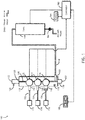
- FIG 1 A first figure.
- a manifold assembly system 100 may include a manifold body 110 configured for distribution of hot water to an aircraft hot beverage maker.
- a center channel 140 may extend from end to end along a vertical axis.
- An input port 160 may supply the manifold center channel 140 with hot water from a tank line 158 from a tank 150.
- a chassis connection 118 may function to provide a mechanical coupling with a chassis of an aircraft hot beverage maker.
- three distribution ports for coffee 412, hot water 414, and tea 416 may be vertically aligned along and in fluid connectivity with the center channel 140.
- solenoid valves for coffee brew 112, hot water 114, and tea 116 mechanically couple with each distribution port and function to valve a flow a hot water between the center channel 140 and each of an associated exit fitting for coffee brew 142, hot water 144, and tea 146.
- a top vent port 120 aligned and in fluid connectivity with the center channel 140 may provide function to the manifold assembly for venting during a system fill and offering a source of air for draining of the system during a system drain.
- the top vent port and associated top vent valve and vent fitting 124 may provide function to the manifold assembly system 100 to enable a complete drain of the manifold assembly body 110, the tank line 158 and the tank 150 as a tank drain 162 is opened while aircraft water pressure may be removed.
- the top vent valve may open allowing an exit point for system wide air enabling a complete fill of the tank 150, tank line 158 and center channel 140.
- the top vent port may allow, in molded construction, enabling use of a core pin creating the top vent port 120 as well as a top portion of the center channel 140.
- a bottom flush port 130 may be aligned and in fluid connectivity with the center channel 140.
- the bottom flush port 130 may provide multiple function.
- One function may include an ability, in molded construction, to enable a core pin to be used creating the bottom flush port 130 as well as a bottom portion of the center channel 140.
- An additional function may include an ability to remove a bottom flush port plug 132 allowing for efficient cleaning as well as a gravity removal of debris from the manifold assembly 110.
- a flush port plug 132 may mechanically couple and seal the bottom flush port 130 during operation while enabling efficient flushing and gravity drain of the manifold body 110.
- a controller 180 may operatively couple with each solenoid valve including brew 112, hot water 114, tea 116 to control function (e.g., open and close) of each solenoid valve to control function of each valve.
- the controller 180 may also provide additional function to the hot beverage maker.
- a tangible, non-transitory memory 184 may be configured to communicate with the controller, the tangible, non-transitory memory having instructions stored therein that, in response to execution by the controller, cause the controller to perform function associated with the hot beverage maker.
- such function may include receiving an input from a user of the aircraft hot beverage device via a user selector 182 and sending a signal (electric and or data) to operate each solenoid valves controlling the flow of hot water from the center channel 140 to one of the fittings for brew 142, hot water 144, and tea 146.
- Coupled with each fitting 142 144 146, associated lines for brew 152, hot water 154, and tea 156 may provide connectivity to each dispenser of the hot beverage maker including an associated brew dispenser 172, hot water dispenser 174, and tea dispenser 176.
- a user may select a coffee button on the user selector 182 sending a signal to the controller 180.
- the controller 180 may send an open signal to the brew solenoid valve 112 causing the valve to open and provide hot water from the center channel 140 through the brew distribution port 412 ( FIG. 4 ) to the brew line 152 and ultimately the brew dispenser 172.
- the controller may receive a full indication from the hot beverage maker and send a close signal to the brew solenoid valve 112 stopping the hot water flow from the center channel 140.
- FIG. 2 a diagram of an installed manifold assembly within a beverage maker in accordance with an embodiment of the inventive concepts disclosed herein is shown.
- An installed manifold assembly 200 may detail an accurate representation of element alignment and installation.
- each solenoid valve 112 114 116 may be vertically aligned and connected with each associated line for brew 152, hot water 154, and tea 156.
- the tea line 156 may include an integrated flow regulator 256.
- the flow regulator 256 may function to reduce a flow of hot water as the flow may leave the tea solenoid valve 116.
- Exploded view 300 may indicate each element associated with the manifold assembly.
- the manifold body 110 including each of the top vent port 120 and the bottom flush port 130.
- Each exit fitting including brew exit fitting 142, hot water exit fitting 144, and tea exit fitting 146 may be indicated and oriented parallel to a longitudinal axis 354 and approximately normal to a vertical axis 350 as well as approximately normal to each of the distribution ports 412, 414, 416.
- tea exit fitting 146 may be specifically configured to receive and integrate with the flow regulator 256 to maintain a low flow rate to maintain water temperature and limit leak exposure downstream in any lines.
- the term approximately may be used in the specification and claims.
- the term approximately may be defined as plus or minus 20% of the value to which the term is referred.
- approximately normal may include values +/- 20% of 90 degrees inclusive of 72 degrees to 108 degrees.
- Each solenoid valve may include a plunger 312, an O ring 314, a guide 316 and a retaining nut 318 each oriented approximately parallel to a lateral axis 352.
- the plunger 312 may function as the physical barrier to the flow of hot water from the center channel 140 to the brew exit fitting 142.
- a clip 320 may function to retain the top vent valve 122 in place within the top vent port 120.
- the clip 320 may be easily removed by a user to remove the top vent valve 122 allowing efficient access to the center channel 140 for ease in flushing and descaling the entire system.
- Manifold body view 400 may indicate the manifold body 110 without additional elements attached.
- a total overall vertical dimension of the manifold body 110 may be approximately 4.503 inches from a top end proximal with the upper vent port 120 to the bottom end proximal with the bottom flush port 130.
- each distribution port for brew 412, hot water 414, and tea 416 configured to receive each associated solenoid valve for operation.
- Each distribution port 412 414 416 may be vertically separated by approximately 1.06 inches (26.9 mm) and displaced from the vertical axis 350 by approximately 0.19 inches (4.88 mm).
- each distribution port 412 414 416 may clearly indicate each distribution port 412 414 416 oriented approximately normal to the vertical axis 350.
- Each exit fitting 142 144 146 may also be indicated aligned approximately normal to both the distribution ports 412 414 416 as well as the vertical axis 350.
- a lateral dimension may be defined as normal to the vertical axis and aligned with wings of the aircraft in which the manifold is installed.
- a lateral dimension of the manifold body may be approximately 1.819 inches (46.2 mm).
- FIG. 4C may be the center channel 140 detailing a diameter of the center channel 140 being smallest in the vertical center of the manifold body 110.
- the center channel inside diameter is approximately 0.19 inches at its smallest and opening to a wider inside diameter at each of the top vent port 120 (approximately 0.503 inches (12.78 mm)) and the bottom flush port 130 (approximately 0.258 inches (0.66 mm)).
- each core pin may be removable after the mold has cured. In this manner, each of the opposite ports, the top vent port 120 and the bottom flush port 130 may maintain a function during construction as well as a function during operation.
- Vent valve views 500 may indicate each element of the vent valve 122.
- Vent valve 122 may include a vent valve base 502, a lower port 504, a vent valve ball 506, an upper port 508, a vent valve housing 510, and a connection port 512.
- the vent valve ball 506 may remain is the lower position allowing air to pass through the vent valve 122 and out through the vent valve fitting 124. Once the water level reaches the vent valve ball 506, the ball may float and rise to mate with the upper port 508 and prevent pressurized water from the center channel 140 to escape the system.
- the vent valve ball 506 may fall as water may flow out of the valve 122 allowing air to ventilate the center channel 140 as well as the tank line 158 and the tank 150.
- Hot beverage maker view 600 may detail each element of the overall hot beverage system.
- a hot beverage maker 610 may include an aircraft water inlet 612, a power connector 614, and a manifold wiring harness 616.
- Controller 180 may be sited on a back cover where it may maintain data connectivity with each of the elements including the manifold assembly via a manifold wiring harness 616.
- embodiments of the inventive concepts disclosed herein may provide a lightweight, molded manifold assembly solution comprising each desired element incorporated within the manifold assembly.
- embodiments of the methods according to the inventive concepts disclosed herein may include one or more of the steps described herein. Further, such steps may be carried out in any desired order and two or more of the steps may be carried out simultaneously with one another. Two or more of the steps disclosed herein may be combined in a single step, and in some embodiments, one or more of the steps may be carried out as two or more sub-steps. Further, other steps or sub-steps may be carried in addition to, or as substitutes to one or more of the steps disclosed herein.
Applications Claiming Priority (1)
| Application Number | Priority Date | Filing Date | Title |
|---|---|---|---|
| US16/293,368 US10864990B2 (en) | 2019-03-05 | 2019-03-05 | Manifold assembly with integrated vent and flow control ports |
Publications (2)
| Publication Number | Publication Date |
|---|---|
| EP3714745A1 true EP3714745A1 (fr) | 2020-09-30 |
| EP3714745B1 EP3714745B1 (fr) | 2023-09-13 |
Family
ID=69526081
Family Applications (1)
| Application Number | Title | Priority Date | Filing Date |
|---|---|---|---|
| EP20155906.9A Active EP3714745B1 (fr) | 2019-03-05 | 2020-02-06 | Ensemble collecteur doté de ports de contrôle du débit et de ventilation intégrés |
Country Status (3)
| Country | Link |
|---|---|
| US (1) | US10864990B2 (fr) |
| EP (1) | EP3714745B1 (fr) |
| CN (1) | CN111657744B (fr) |
Cited By (1)
| Publication number | Priority date | Publication date | Assignee | Title |
|---|---|---|---|---|
| EP4105534A1 (fr) * | 2021-06-15 | 2022-12-21 | Goodrich Corporation | Ensemble connecteur |
Citations (6)
| Publication number | Priority date | Publication date | Assignee | Title |
|---|---|---|---|---|
| GB995919A (en) * | 1962-07-27 | 1965-06-23 | Stuart Grahame Ross | Air bleed valve |
| US20030003208A1 (en) * | 1998-08-11 | 2003-01-02 | Lassota Zbigniew G. | Coffee brewer with independent control of dispense period and batch quantity and method |
| US20050247359A1 (en) * | 2004-05-05 | 2005-11-10 | Hiser Nicholas R | Pressure relieving coupler manifold with internal velocity fuse |
| US20070272085A1 (en) * | 2006-03-31 | 2007-11-29 | C&D Zodiac, Inc. | Beverage maker |
| US20120234180A1 (en) * | 2011-03-11 | 2012-09-20 | Rachel Kuniyoshi Cabe | Water venting systems and methods for aircraft beverage makers |
| EP2502531A1 (fr) * | 2009-11-18 | 2012-09-26 | Jofemar, S.A. | Système de chaudière et distributeur pour un distributeur de boissons chaudes |
Family Cites Families (18)
| Publication number | Priority date | Publication date | Assignee | Title |
|---|---|---|---|---|
| US3190310A (en) * | 1960-12-16 | 1965-06-22 | American Radiator & Standard | Gang valve arrangement |
| US3516638A (en) * | 1968-10-31 | 1970-06-23 | Spraying Systems Co | Flow diverter ball valve |
| US4562863A (en) * | 1984-01-27 | 1986-01-07 | Claussen Robert L | Liquid flow indicator for farm implements |
| US4602145A (en) * | 1984-07-23 | 1986-07-22 | Bloomfield Industries, Inc. | Tap-off hot water system for electric beverage making device |
| DE4036068A1 (de) * | 1990-11-13 | 1992-05-14 | Mueller A & K Gmbh Co Kg | Ausgabeventilanordnung fuer bruehwasser, insbesondere an einem heissgetraenkeautomaten, sowie betriebsverfahren zur steuerung der ausgabeventilanordnung |
| DE29716779U1 (de) * | 1997-09-18 | 1999-01-28 | Dumser Metallbau Gmbh & Co Kg | Verteiler für einen mit einem flüssigen Medium betriebenen Kreislauf einer Wärme- oder Kälteversorgungsanlage |
| JP4244254B2 (ja) * | 1999-04-30 | 2009-03-25 | 株式会社キッツエスシーティー | 集積化ガス制御装置 |
| JP3759898B2 (ja) * | 2001-11-19 | 2006-03-29 | 象印マホービン株式会社 | 飲料抽出装置 |
| CN2712227Y (zh) * | 2004-04-21 | 2005-07-27 | 杭州司迈特电器有限公司 | 一种自循环除菌的温热型饮水机 |
| US7640845B2 (en) * | 2005-09-12 | 2010-01-05 | Keurig, Incorporated | Drain for beverage forming machine |
| JP5641364B2 (ja) * | 2008-06-02 | 2014-12-17 | イートン コーポレーションEaton Corporation | バルブマニホールド |
| CN201492284U (zh) * | 2009-09-07 | 2010-06-02 | 依莱克顿(宁波)电器科技有限公司 | 带热水杀菌的饮水机 |
| FR2960806B1 (fr) * | 2010-06-04 | 2012-06-22 | Mann & Hummel Gmbh | Procede de fabrication d'un assemblage de soupapes a clapet pour un collecteur d'admission d'air et assemblage realise |
| US10107407B2 (en) * | 2010-09-28 | 2018-10-23 | Parker-Hannifin Corporation | Modular valve manifold system |
| KR101082964B1 (ko) * | 2011-05-25 | 2011-11-11 | 이희곤 | 스케일 제거기능을 갖춘 온수분배기 |
| US9273449B2 (en) * | 2012-10-04 | 2016-03-01 | B/E Aerospace, Inc. | Aircraft galley water distribution manifold |
| EP2997198B1 (fr) * | 2013-05-14 | 2019-07-03 | C&D Zodiac, Inc. | Système d'eau potable de toilettes |
| US9878892B2 (en) * | 2016-02-05 | 2018-01-30 | Pepsico, Inc. | Vertical beverage dispensing manifolds, dispensers including the same, and methods of dispensing a beverage |
-
2019
- 2019-03-05 US US16/293,368 patent/US10864990B2/en active Active
- 2019-12-26 CN CN201911362130.9A patent/CN111657744B/zh active Active
-
2020
- 2020-02-06 EP EP20155906.9A patent/EP3714745B1/fr active Active
Patent Citations (6)
| Publication number | Priority date | Publication date | Assignee | Title |
|---|---|---|---|---|
| GB995919A (en) * | 1962-07-27 | 1965-06-23 | Stuart Grahame Ross | Air bleed valve |
| US20030003208A1 (en) * | 1998-08-11 | 2003-01-02 | Lassota Zbigniew G. | Coffee brewer with independent control of dispense period and batch quantity and method |
| US20050247359A1 (en) * | 2004-05-05 | 2005-11-10 | Hiser Nicholas R | Pressure relieving coupler manifold with internal velocity fuse |
| US20070272085A1 (en) * | 2006-03-31 | 2007-11-29 | C&D Zodiac, Inc. | Beverage maker |
| EP2502531A1 (fr) * | 2009-11-18 | 2012-09-26 | Jofemar, S.A. | Système de chaudière et distributeur pour un distributeur de boissons chaudes |
| US20120234180A1 (en) * | 2011-03-11 | 2012-09-20 | Rachel Kuniyoshi Cabe | Water venting systems and methods for aircraft beverage makers |
Cited By (1)
| Publication number | Priority date | Publication date | Assignee | Title |
|---|---|---|---|---|
| EP4105534A1 (fr) * | 2021-06-15 | 2022-12-21 | Goodrich Corporation | Ensemble connecteur |
Also Published As
| Publication number | Publication date |
|---|---|
| CN111657744A (zh) | 2020-09-15 |
| EP3714745B1 (fr) | 2023-09-13 |
| US20200283152A1 (en) | 2020-09-10 |
| US10864990B2 (en) | 2020-12-15 |
| CN111657744B (zh) | 2023-12-19 |
Similar Documents
| Publication | Publication Date | Title |
|---|---|---|
| US9475582B2 (en) | Aircraft potable-water system | |
| US2313797A (en) | Blending apparatus | |
| KR20130009777A (ko) | 밸브 시스템 | |
| EP3714745A1 (fr) | Ensemble collecteur doté de ports de contrôle du débit et de ventilation intégrés | |
| US20070089790A1 (en) | Assembly for connecting a water supply to heating systems with a water heater | |
| EP2407695A2 (fr) | Soupape de douche dissimulée multifonction | |
| EP1120498A2 (fr) | Dispositif pour distribuer et mélanger de l'eau | |
| US3190310A (en) | Gang valve arrangement | |
| US10557771B2 (en) | Test cylinder of valve assembly and connection structure for the same | |
| US20150216133A1 (en) | Valve box with electrovalves for remotely controlled irrigation systems | |
| EP0269152B1 (fr) | Dispositif de nettoyage d'installations de soutirage et moyens de changement automatique de fût | |
| CN204852479U (zh) | 集成分水器 | |
| US5287567A (en) | Hydraulic isolation manifold | |
| EP2820996B1 (fr) | Dispositif de soupage pour un système aquastop utilisé dans un appareil ménager tel que lave-vaiselle ou machine à laver | |
| US3540476A (en) | Mounting manifold for dispenser valves | |
| US2174965A (en) | Multiple valve control | |
| KR102497767B1 (ko) | 다중 구성을 갖는 삼중 제빙기 밸브 | |
| US11180906B2 (en) | Supply assembly for use with multiple lines of a hydrant | |
| US9193463B2 (en) | Lavatory potable water system | |
| CN212839530U (zh) | 一种利用或门选择的油路控制单元 | |
| US10794508B2 (en) | Atmosphere control manifold | |
| CN111854263A (zh) | 制冷设备的水路系统及具有其的制冷设备 | |
| CN204678692U (zh) | 一种可拆卸开水器 | |
| CN204900941U (zh) | 一种控水装置 | |
| CN201301985Y (zh) | 一种用于洁身器的水压调节阀 |
Legal Events
| Date | Code | Title | Description |
|---|---|---|---|
| PUAI | Public reference made under article 153(3) epc to a published international application that has entered the european phase |
Free format text: ORIGINAL CODE: 0009012 |
|
| STAA | Information on the status of an ep patent application or granted ep patent |
Free format text: STATUS: THE APPLICATION HAS BEEN PUBLISHED |
|
| AK | Designated contracting states |
Kind code of ref document: A1 Designated state(s): AL AT BE BG CH CY CZ DE DK EE ES FI FR GB GR HR HU IE IS IT LI LT LU LV MC MK MT NL NO PL PT RO RS SE SI SK SM TR |
|
| AX | Request for extension of the european patent |
Extension state: BA ME |
|
| STAA | Information on the status of an ep patent application or granted ep patent |
Free format text: STATUS: REQUEST FOR EXAMINATION WAS MADE |
|
| 17P | Request for examination filed |
Effective date: 20210330 |
|
| RBV | Designated contracting states (corrected) |
Designated state(s): AL AT BE BG CH CY CZ DE DK EE ES FI FR GB GR HR HU IE IS IT LI LT LU LV MC MK MT NL NO PL PT RO RS SE SI SK SM TR |
|
| RAP3 | Party data changed (applicant data changed or rights of an application transferred) |
Owner name: B/E AEROSPACE, INC. |
|
| STAA | Information on the status of an ep patent application or granted ep patent |
Free format text: STATUS: EXAMINATION IS IN PROGRESS |
|
| 17Q | First examination report despatched |
Effective date: 20220729 |
|
| GRAP | Despatch of communication of intention to grant a patent |
Free format text: ORIGINAL CODE: EPIDOSNIGR1 |
|
| STAA | Information on the status of an ep patent application or granted ep patent |
Free format text: STATUS: GRANT OF PATENT IS INTENDED |
|
| INTG | Intention to grant announced |
Effective date: 20230425 |
|
| GRAS | Grant fee paid |
Free format text: ORIGINAL CODE: EPIDOSNIGR3 |
|
| GRAA | (expected) grant |
Free format text: ORIGINAL CODE: 0009210 |
|
| STAA | Information on the status of an ep patent application or granted ep patent |
Free format text: STATUS: THE PATENT HAS BEEN GRANTED |
|
| AK | Designated contracting states |
Kind code of ref document: B1 Designated state(s): AL AT BE BG CH CY CZ DE DK EE ES FI FR GB GR HR HU IE IS IT LI LT LU LV MC MK MT NL NO PL PT RO RS SE SI SK SM TR |
|
| REG | Reference to a national code |
Ref country code: CH Ref legal event code: EP |
|
| REG | Reference to a national code |
Ref country code: DE Ref legal event code: R096 Ref document number: 602020017475 Country of ref document: DE |
|
| REG | Reference to a national code |
Ref country code: IE Ref legal event code: FG4D |
|
| P01 | Opt-out of the competence of the unified patent court (upc) registered |
Effective date: 20230922 |
|
| REG | Reference to a national code |
Ref country code: LT Ref legal event code: MG9D |
|
| REG | Reference to a national code |
Ref country code: NL Ref legal event code: MP Effective date: 20230913 |
|
| PG25 | Lapsed in a contracting state [announced via postgrant information from national office to epo] |
Ref country code: GR Free format text: LAPSE BECAUSE OF FAILURE TO SUBMIT A TRANSLATION OF THE DESCRIPTION OR TO PAY THE FEE WITHIN THE PRESCRIBED TIME-LIMIT Effective date: 20231214 |
|
| PG25 | Lapsed in a contracting state [announced via postgrant information from national office to epo] |
Ref country code: SE Free format text: LAPSE BECAUSE OF FAILURE TO SUBMIT A TRANSLATION OF THE DESCRIPTION OR TO PAY THE FEE WITHIN THE PRESCRIBED TIME-LIMIT Effective date: 20230913 Ref country code: RS Free format text: LAPSE BECAUSE OF FAILURE TO SUBMIT A TRANSLATION OF THE DESCRIPTION OR TO PAY THE FEE WITHIN THE PRESCRIBED TIME-LIMIT Effective date: 20230913 Ref country code: NO Free format text: LAPSE BECAUSE OF FAILURE TO SUBMIT A TRANSLATION OF THE DESCRIPTION OR TO PAY THE FEE WITHIN THE PRESCRIBED TIME-LIMIT Effective date: 20231213 Ref country code: LV Free format text: LAPSE BECAUSE OF FAILURE TO SUBMIT A TRANSLATION OF THE DESCRIPTION OR TO PAY THE FEE WITHIN THE PRESCRIBED TIME-LIMIT Effective date: 20230913 Ref country code: LT Free format text: LAPSE BECAUSE OF FAILURE TO SUBMIT A TRANSLATION OF THE DESCRIPTION OR TO PAY THE FEE WITHIN THE PRESCRIBED TIME-LIMIT Effective date: 20230913 Ref country code: HR Free format text: LAPSE BECAUSE OF FAILURE TO SUBMIT A TRANSLATION OF THE DESCRIPTION OR TO PAY THE FEE WITHIN THE PRESCRIBED TIME-LIMIT Effective date: 20230913 Ref country code: GR Free format text: LAPSE BECAUSE OF FAILURE TO SUBMIT A TRANSLATION OF THE DESCRIPTION OR TO PAY THE FEE WITHIN THE PRESCRIBED TIME-LIMIT Effective date: 20231214 Ref country code: FI Free format text: LAPSE BECAUSE OF FAILURE TO SUBMIT A TRANSLATION OF THE DESCRIPTION OR TO PAY THE FEE WITHIN THE PRESCRIBED TIME-LIMIT Effective date: 20230913 |
|
| REG | Reference to a national code |
Ref country code: AT Ref legal event code: MK05 Ref document number: 1610394 Country of ref document: AT Kind code of ref document: T Effective date: 20230913 |
|
| PG25 | Lapsed in a contracting state [announced via postgrant information from national office to epo] |
Ref country code: NL Free format text: LAPSE BECAUSE OF FAILURE TO SUBMIT A TRANSLATION OF THE DESCRIPTION OR TO PAY THE FEE WITHIN THE PRESCRIBED TIME-LIMIT Effective date: 20230913 |
|
| PG25 | Lapsed in a contracting state [announced via postgrant information from national office to epo] |
Ref country code: IS Free format text: LAPSE BECAUSE OF FAILURE TO SUBMIT A TRANSLATION OF THE DESCRIPTION OR TO PAY THE FEE WITHIN THE PRESCRIBED TIME-LIMIT Effective date: 20240113 |