EP3714182B1 - Satellite gear carrier for for a brake reduction gear, and method for manufacturing such satellite gear carrier - Google Patents
Satellite gear carrier for for a brake reduction gear, and method for manufacturing such satellite gear carrier Download PDFInfo
- Publication number
- EP3714182B1 EP3714182B1 EP18814498.4A EP18814498A EP3714182B1 EP 3714182 B1 EP3714182 B1 EP 3714182B1 EP 18814498 A EP18814498 A EP 18814498A EP 3714182 B1 EP3714182 B1 EP 3714182B1
- Authority
- EP
- European Patent Office
- Prior art keywords
- planet carrier
- plate
- planet
- groove
- rotation
- Prior art date
- Legal status (The legal status is an assumption and is not a legal conclusion. Google has not performed a legal analysis and makes no representation as to the accuracy of the status listed.)
- Active
Links
- 238000004519 manufacturing process Methods 0.000 title claims description 25
- 230000009467 reduction Effects 0.000 title claims description 10
- 238000000034 method Methods 0.000 title claims description 8
- 238000005520 cutting process Methods 0.000 claims description 6
- 239000004033 plastic Substances 0.000 claims description 6
- 239000000463 material Substances 0.000 claims description 5
- 238000005452 bending Methods 0.000 claims description 4
- 238000003780 insertion Methods 0.000 claims description 4
- 230000037431 insertion Effects 0.000 claims description 4
- 239000007769 metal material Substances 0.000 claims description 2
- 238000007493 shaping process Methods 0.000 claims description 2
- 238000011144 upstream manufacturing Methods 0.000 description 8
- 230000007246 mechanism Effects 0.000 description 5
- 230000008878 coupling Effects 0.000 description 4
- 238000010168 coupling process Methods 0.000 description 4
- 238000005859 coupling reaction Methods 0.000 description 4
- 238000004080 punching Methods 0.000 description 3
- 230000008901 benefit Effects 0.000 description 2
- 238000002347 injection Methods 0.000 description 2
- 239000007924 injection Substances 0.000 description 2
- 238000000465 moulding Methods 0.000 description 2
- 230000008569 process Effects 0.000 description 2
- 230000002787 reinforcement Effects 0.000 description 2
- 230000000712 assembly Effects 0.000 description 1
- 238000000429 assembly Methods 0.000 description 1
- 230000004323 axial length Effects 0.000 description 1
- 230000005540 biological transmission Effects 0.000 description 1
- 230000015572 biosynthetic process Effects 0.000 description 1
- 239000000969 carrier Substances 0.000 description 1
- 230000008859 change Effects 0.000 description 1
- 239000003638 chemical reducing agent Substances 0.000 description 1
- 230000000295 complement effect Effects 0.000 description 1
- 238000002788 crimping Methods 0.000 description 1
- 239000002184 metal Substances 0.000 description 1
- 239000011347 resin Substances 0.000 description 1
- 229920005989 resin Polymers 0.000 description 1
- 238000007789 sealing Methods 0.000 description 1
- 238000005245 sintering Methods 0.000 description 1
- 239000007787 solid Substances 0.000 description 1
- 239000000126 substance Substances 0.000 description 1
- 229920001169 thermoplastic Polymers 0.000 description 1
- 229920001187 thermosetting polymer Polymers 0.000 description 1
- 239000004416 thermosoftening plastic Substances 0.000 description 1
- 238000003466 welding Methods 0.000 description 1
Images

Classifications
-
- F—MECHANICAL ENGINEERING; LIGHTING; HEATING; WEAPONS; BLASTING
- F16—ENGINEERING ELEMENTS AND UNITS; GENERAL MEASURES FOR PRODUCING AND MAINTAINING EFFECTIVE FUNCTIONING OF MACHINES OR INSTALLATIONS; THERMAL INSULATION IN GENERAL
- F16D—COUPLINGS FOR TRANSMITTING ROTATION; CLUTCHES; BRAKES
- F16D65/00—Parts or details
- F16D65/14—Actuating mechanisms for brakes; Means for initiating operation at a predetermined position
-
- F—MECHANICAL ENGINEERING; LIGHTING; HEATING; WEAPONS; BLASTING
- F16—ENGINEERING ELEMENTS AND UNITS; GENERAL MEASURES FOR PRODUCING AND MAINTAINING EFFECTIVE FUNCTIONING OF MACHINES OR INSTALLATIONS; THERMAL INSULATION IN GENERAL
- F16H—GEARING
- F16H57/00—General details of gearing
- F16H57/08—General details of gearing of gearings with members having orbital motion
- F16H57/082—Planet carriers
-
- F—MECHANICAL ENGINEERING; LIGHTING; HEATING; WEAPONS; BLASTING
- F16—ENGINEERING ELEMENTS AND UNITS; GENERAL MEASURES FOR PRODUCING AND MAINTAINING EFFECTIVE FUNCTIONING OF MACHINES OR INSTALLATIONS; THERMAL INSULATION IN GENERAL
- F16D—COUPLINGS FOR TRANSMITTING ROTATION; CLUTCHES; BRAKES
- F16D2125/00—Components of actuators
- F16D2125/18—Mechanical mechanisms
- F16D2125/44—Mechanical mechanisms transmitting rotation
- F16D2125/46—Rotating members in mutual engagement
- F16D2125/50—Rotating members in mutual engagement with parallel non-stationary axes, e.g. planetary gearing
Definitions
- the present invention relates to a planet carrier for a differential reduction brake actuator and to a method of manufacturing a planet carrier.
- the field of the invention is that of braking systems for automobiles.
- the invention proposes a planet carrier comprising a frame arranged and configured to carry planet gears distributed angularly around the axis of the planet carrier.
- the armature comprises a single plate arranged and configured to form a cylindrical casing which has openings through which a planet pinion projects radially.
- the plate has a deformation producing a longitudinal groove on at least one side of the openings, along a direction parallel to the axis of the planet carrier, so as to support one or more rotational guide shafts projecting from said planet pinions .
- the parking and/or emergency brake function consists in applying and maintaining a tightening of brake pads linked to a part integral with the chassis, on a rotating mobile part which is linked to one or several wheels, typically a disc or a drum.
- the screw-nut system is operated by a gear motor.
- Some gear reduction mechanisms include one or more planetary gear sets.
- An epicyclic gear train comprises two sun gears (a first sun gear, called inner, and a second sun gear, called outer) and satellites carried by a planet carrier. Each satellite meshes simultaneously with the two sun gears which are arranged coaxially.
- the outer sun gear is internally toothed, and is often referred to as the "crown”.
- the inner planetary is often referred to simply as "the planetary”, without further precision.
- the document FR 3 031 154 A1 discloses a reducer which includes two stages of reduction. With reference to the Figure 1 , it comprises an upstream reduction stage formed by an upstream planetary gear train with satellites 131 and fixed ring gear 121. This upstream gear is driven at the input by its inner sun gear 111, itself driven by a toothed shaft bearing a drive cavity 119 This upstream planetary gear train drives its planet carrier 130 on its output.
- the second stage comprises an epicyclic gear train driven at the input by the sun gear 139, and whose satellites 141 mesh with a fixed ring gear 121, here the same as for the upstream epicyclic gear train.
- this movable crown 151 carries a thread 152 coaxial with the epicyclic trains, and cooperating with an internal thread 161 of the piston 16 for the drive in translation.
- the fixed crown 121 is common to the two planetary gear sets, and the differential satellites 141 are common to the two crowns 121, 151 of the differential gear set, which generally carry a different number of teeth from one to the other.
- the planet carrier is generally machined or sintered or even molded, in metal or plastic.
- the planet carrier comprises a frame of simply tubular or approximately general shape and open at its axial ends.
- the armature of the planet carrier 140 has the shape of a tube, the thickness of the wall of which is such that the wall encompasses the rotation shaft of each satellite.
- the planet carrier is machined radially along its circumference so as to produce several windows 149, of substantially rectangular shape, each window being provided to receive a satellite. Each window is delimited longitudinally at each end by a support part of the tube forming a rotation support for each satellite.
- a bore is machined on each transverse face of a support part to receive a rotation shaft of a satellite.
- the planet carrier forms a cage for the satellites.
- Each support part forming a transverse flange for each satellite end and the satellites protrude radially from the circumference of the planet carrier.
- Each guide shaft is crimped in a bore of the planet carrier, each satellite being mounted freely in rotation on a guide shaft.
- Each satellite has a through longitudinal bore, which opens onto each transverse face and is arranged and configured to receive a guide shaft.
- An object of the invention is to propose a planet carrier making it possible to facilitate the mounting of the satellites on the planet carrier.
- Another object of the invention is to propose a method of manufacturing said planet carrier in order to lower its manufacturing cost.
- the invention proposes a planet carrier of the type without an input or output coupling shaft, and more particularly a planet carrier for an epicyclic gear train of a differential reduction brake actuator for actuation of a motor vehicle parking brake.
- the planet carrier comprises a frame arranged and configured to carry planet pinions distributed angularly around the axis of the planet carrier.
- the satellite pinions are angularly distributed in a regular manner along the frame.
- the armature comprises at least one plate arranged and configured to form a cylindrical casing, said plate having openings through which a planet pinion projects radially.
- it is a plate forming a piece unique coming of material, and for example a single plate.
- the plate has a succession of longitudinal grooves, extending from at least one side of the openings along a direction parallel to the axis of the planet carrier, so as to support one or more rotational guide shafts projecting from said satellite gears.
- this groove is made by a part of the plate which is deformed into an arc of a circle, typically without modifying its thickness, around the axis of this arc of a circle.
- This deformation is for example carried out by plastic deformation, for example by stamping or stamping, for example simultaneously with the cutting of the openings or in the same series of operations carried out successively in an automated manner under a press.
- this groove can also be produced by other processes modifying the thickness of the plate at this location, for example by punching and/or by removing material.
- a planet carrier according to the invention facilitates the operation of mounting the planet gears on the planet carrier, and facilitates its manufacture, and thus lowers its manufacturing cost.
- the term “plate” is understood here to mean a part that is thin along one dimension with respect to its other dimensions, for example by at most 10%, and typically of a substantially constant thickness, for example to within 20%.
- the armature plate has a constant thickness along the circumference of the armature.
- the plate, at the level of each groove, has for example a constant thickness, equal to the rest of the reinforcement, for example with a tolerance of plus or minus 20% (twenty percent).
- Each groove makes it possible to produce a rotation bearing to guide in rotation a guide shaft of a planet pinion.
- a longitudinal groove is provided on each side of the openings along a direction parallel to the axis of the planet carrier, so as to support one or more rotational guide shafts projecting from said planet pinions.
- Each groove opens radially through a passage whose width is less than the diameter of the rotating guide shaft that it receives, so as to allow insertion by radial clipping of said guide shaft.
- This characteristic makes it possible to hold each satellite pinion in position in a groove.
- This characteristic is particularly advantageous for facilitating the mounting of the planet carrier in an actuator, once provided with the planet gears.
- the groove is produced for example according to one of the following two embodiments.
- the deformation of the plate forming the groove is such that it extends towards the inside of the planet carrier in a direction radial to the axis of rotation of the planet carrier, that is to say say while approaching the axis of rotation; the opening of the groove then opening out towards the outside of the planet carrier.
- the deformation of the plate forming the groove is such that it extends outwards in a direction radial to the axis of rotation of the planet carrier, that is to say in s' moving away from the axis of rotation, the opening of the groove then opening out towards the inside of the planet carrier.
- the armature is arranged and configured to form only a cylindrical casing, with no torque transmission element from the planet carrier to other mechanical elements.
- the cylindrical casing substantially forms a tube, opening out at each axial end without a sealing flange. It can consist of one or more plates. These characteristics facilitate the manufacture of the planet carrier.
- the reinforcement consists of a single plate, forming the entire periphery of the cage and/or over a single thickness. This characteristic facilitates the manufacture and assembly of a planet carrier and thus lowers the cost of manufacture.
- the planet carrier is made of metallic material or of plastic material.
- the planet carrier made of plastic material is for example produced by molding, for example using a thermal process such as injection of thermoplastic or thermosetting plastic, and/or of a chemical resin.
- the planet carrier comprises at least one planet pinion.
- the at least one satellite pinion has one or at least two rotation guide shafts.
- each shaft is placed in a bore made on either side of a planet pinion, the two bores being coaxial.
- Each shaft is designed to project axially on either side of a toothed portion of the pinion.
- each rotation guide shaft is arranged and configured to be guided in rotation by a groove in the frame of the planet carrier.
- the planet carrier and planet gear assembly thus proposed has the advantage of being easier to manufacture and to assemble, thus making it possible to lower its manufacturing cost.
- the axial length of the satellites is between 2 mm and 50 mm, preferably between 5 and 30 mm, more preferably between 15 and 25 mm, for example equal to 19 mm, or 20 mm or 21 mm.
- the diameter of the satellites is between 2 mm and 40 mm, preferably between 4 and 30 mm, more preferably between 6 and 20 mm, for example equal to 9 mm, or 10 mm or 11 mm.
- the plate can be cut from a larger plate, for example from a roll.
- the portions to be cut are rectangular. They are for example made by stamping or stamping.
- the formation of the grooves is for example carried out by punching, stamping, stamping or stamping.
- the step of bending the plate can be carried out by bending.
- the manufacturing method according to the invention thus makes it possible to lower the manufacturing cost of a planet carrier.
- a fourth aspect of the invention which is in accordance with one of the first two aspects or with the first two aspects, there is proposed a method of manufacturing a planet carrier characterized in that the planet carrier is molded by injection.
- each groove opens out radially through a passage whose width is less than the diameter of the rotation guide shaft that it receives, so that during the step of introducing a satellite into a groove, said step includes an operation of clipping each shaft of a planet gear into each groove.
- each guide shaft is moved in a substantially radial direction with respect to the axis of rotation of the planet carrier to be inserted into a groove, either by moving away from the axis of rotation, or approaching the axis of rotation according to the conformation of the deformations forming the grooves.
- a brake actuator comprising a planet carrier.
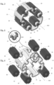
- FIGURES 3 and 4 illustrate a planet carrier 10 of the type without a coupling shaft or without a coupling part between the planet carrier and a rotating shaft.
- the planet carrier is intended to cooperate with only satellite pinions 30, that is to say that the rotation of the cage does not transmit any significant force to any other mechanical element of the mechanism, or any force entering the dynamic chain of actuation.
- FIGURE 7 illustrates such a planet carrier 10, said without coupling part, forming part of a planetary gear train with differential reduction within a brake actuator, for example for actuating a motor vehicle parking brake.
- the planet carrier 10, carrying the planet pinions 30, is inserted between a central sun gear 11 and an internally toothed crown 12; the three elements being arranged coaxially with respect to the axis of rotation A10. Only the planet pinions 30 are in simultaneous contact with the pinion 11 and the crown 12.
- Each planet pinion 30 is carried by the planet carrier 10, by means of one or two rotation guide shafts 31 around a axis of rotation A30.
- This assembly forms for example part of a planetary gear train with differential reduction, for example within a mechanism similar to that of the FIGURE 1 .
- the planet carrier 10 and its planets 30 according to the invention can for example replace the planet carrier 140 and the planets 141 of the FIGURES 1, 2a and 2b .
- the planet carrier 10 forms a frame arranged and configured to carry planet pinions 30 distributed angularly around the axis A10 of the planet carrier and along the frame.
- the satellite pinions 30 are here distributed angularly in a regular manner along said frame.
- the armature consists of a single plate 20 arranged and configured to form a generally cylindrical envelope, so that the armature has the general shape of a circular tube, which is entirely open at each of its two ends.
- the frame has openings 21 through which satellite pinions 30 protrude radially, on the inside and on the outside, see FIGURE 3 .
- the openings 21 are made in the plate 20 so as to each be able to receive a planet pinion, typically only one per opening.
- the openings 21 are of the shape rectangular.
- the openings 21 extend mainly in a direction parallel to the axis of rotation A10 of the planet carrier, and receive elongated satellites along their axis of rotation. These satellites each carry two shafts 31 protruding from the two opposite transverse faces.
- the openings extend mainly in a direction perpendicular to the axis of rotation A10 of the planet carrier, possibly but not necessarily to receive satellites of a larger diameter than along their axis rotation.
- these may comprise only a single shaft projecting from a single one of its transverse faces.
- the shaft or shafts are for example integral with the satellite during its manufacture, for example by molding. According to another example, they are formed for example by one or more preliminary parts on which the body and the teeth of the satellite are molded.
- the shaft or shafts are made by separate parts mounted on the satellite 31 before or after its mounting in the cage 10.
- the armature forms longitudinal grooves 25, the inner surface of which has an arcuate cross-section, to form a bearing each capable of supporting a rotating guide shaft projecting from a planet pinion.
- two grooves 25 are provided for each opening 21.
- the two grooves 25 are arranged coaxially on either side of an opening 21, the axis of said two grooves being parallel to the axis of rotation A10 of the carrier. satellites.
- Each groove 25 opens axially, at a first end towards the outside of the frame, and at a second end on the inside of an opening 21.
- the grooves 25 are made by deformation of the plate 20, as illustrated with FIGURES 3 and 4 and in particular the FIGURE 5 .
- deformation is meant a sudden local change in the contour of the cylindrical envelope.
- the thickness of the plate 20 is here substantially constant along the entire surface of the frame, as well as along the part forming each groove.
- each groove 25 opens radially, on the side, through a passage 26 whose width is less than the diameter of the rotational guide shaft of a satellite pinion that the groove receives, so as to allow insertion by lateral clipping of said guide shaft, ie in a radial direction.
- Each groove 25 has a receiving surface 27 corresponding to the surface of the groove provided to come into contact with the outer surface of a rotating guide shaft 31 of a satellite.
- the receiving surface 27 has a profile in the shape of a horseshoe so that the bottom of the groove has the shape of at least a semicircle, see more in the case of a passage 26 narrower than the shaft 31.
- each planet pinion 30 can be assembled by insertion into its groove according to a movement which brings it closer to the axis of rotation A10 of the planet carrier.
- Each groove projects radially approaching the axis of rotation A10 of the planet carrier.
- the passage of the grooves open radially towards the inside of the planet carrier, so that each planet pinion 30 is inserted into its groove by a movement which separates it from the axis of rotation. A10 from the planet carrier. Each groove then projects radially away from the axis of rotation A10 of the planet carrier.
- a plate 20 of a determined length and width is provided, or cut from a larger plate.
- the term “determined length and width” is understood to mean external dimensions corresponding, or slightly increased, to the dimensions of a cylindrical casing of a planet carrier conforming to the FIGURES 3 or 4 .
- the thickness of plate 20 is substantially constant along its surface.
- the openings 21 have been made in the plate 20.
- a succession of rectangular portions are cut out at regular intervals along the future periphery of the cage of the planet carrier, so as to form the openings 21 to receive the body teeth of the satellites.
- This operation is for example carried out by stamping.
- hooking shapes or cutouts 22, 23 are made at each end of the plate 20, on both sides of the succession of openings 21.
- the hooking cutouts are intended to cause each end with each other and connect them fixedly, for example by cooperation of complementary shapes, after having bent the plate to form a cylindrical envelope.
- a first end of the plate so as to form a containing dovetail 22, also called female
- a second end of said plate opposite the first, so as to form a dovetail contained dovetail 23, also called male
- said dovetails being arranged to fit one inside the other, once the plate 20 is bent and/or curved until the two ends of the plate 20 are connected
- Dovetails can be made by stamping.
- the two ends of the plate can have different hooking shapes. They can also be secured in different ways, for example by welding, crimping, stapling, or by any known means.
- the plate 20 is deformed along a line crossing each opening 21, so as to form two coaxial grooves 25 with axis A30 for each opening 21.
- grooves 25 are arranged and configured to guide the satellite guide shafts in rotation.
- the deformations are for example produced by cold plastic deformation, for example stamping or punching.
- the plate 20 is bent and/or curved so as to form a cylindrical envelope around the axis A10 which will be that of the planet carrier.
- the ends of said plate are then fixed together, here by fitting the dovetails 22, 23 one into the other so as to firmly connect the two ends of the plate.
- each pinion provided with at least one rotational guide shaft and forming a satellite is introduced into an opening, so that said guide shaft in rotation or in a coaxial position in a groove of the armature.
- a rotation guide shaft is inserted in a through bore arranged in a pinion so that said rotation guide shaft protrudes on either side of the pinion.
- the guide shaft has for example a length substantially equal to the length of the pinion and of two grooves.
- the pinion has a bore at each axial end, so as to receive a rotating guide shaft.
- the rotation shafts are for example inserted by shrinking.
- these shafts are integrated into the pinion before assembly. They are for example made in one piece with the pinion, or form an added part around which the pinion is produced by sintering or overmoulding.
- each groove emerges radially via a lateral passage, the width of which is less than the diameter of the drive shaft. rotational guidance that it receives, so that during the step of introducing a planet gear into a groove, said step comprises an operation of clipping each shaft of a planet gear into each groove.
Landscapes
- Engineering & Computer Science (AREA)
- General Engineering & Computer Science (AREA)
- Mechanical Engineering (AREA)
- Retarders (AREA)
Description
La présente invention se rapporte à un porte-satellites pour actionneur de frein à réduction différentielle et à un procédé de fabrication d'un porte-satellites. Le domaine de l'invention est celui des systèmes de freinage pour automobiles.The present invention relates to a planet carrier for a differential reduction brake actuator and to a method of manufacturing a planet carrier. The field of the invention is that of braking systems for automobiles.
L'invention propose un porte-satellites comprenant une armature agencée et configurée pour porter des pignons satellites répartis angulairement autour de l'axe du porte-satellites. L'armature comprend une seule plaque agencée et configurée pour former une enveloppe cylindrique qui présente des ouvertures au travers desquelles fait saillie radialement un pignon satellite. La plaque présente une déformation réalisant une gorge longitudinale d'au moins un côté des ouvertures, le long d'une direction parallèle à l'axe du porte-satellites, de façon à supporter un ou des arbres de guidage en rotation dépassant desdits pignons satellites.The invention proposes a planet carrier comprising a frame arranged and configured to carry planet gears distributed angularly around the axis of the planet carrier. The armature comprises a single plate arranged and configured to form a cylindrical casing which has openings through which a planet pinion projects radially. The plate has a deformation producing a longitudinal groove on at least one side of the openings, along a direction parallel to the axis of the planet carrier, so as to support one or more rotational guide shafts projecting from said planet pinions .
Dans un véhicule, en particulier routier, la fonction de frein de stationnement et/ou de secours consiste à appliquer et maintenir un serrage de patins de freins liés à une partie solidaire du châssis, sur une partie mobile en rotation qui est liée à une ou plusieurs roues, typiquement un disque ou un tambour.In a vehicle, in particular a road vehicle, the parking and/or emergency brake function consists in applying and maintaining a tightening of brake pads linked to a part integral with the chassis, on a rotating mobile part which is linked to one or several wheels, typically a disc or a drum.
Dans les ensembles de freinage utilisant un ou des actionneurs électriques, il est connu d'utiliser un système vis-écrou pour exercer un appui linéaire sur le patin, souvent par l'intermédiaire d'un piston. Ce type de configuration existe pour un fonctionnement électrique seul, ou en combinaison avec un actionnement hydraulique de ce piston ou d'un autre.In braking assemblies using one or more electric actuators, it is known to use a screw-nut system to exert linear support on the pad, often via a piston. This type of configuration exists for electrical operation alone, or in combination with hydraulic actuation of this piston or another.
En général, le système vis-écrou est actionné par un motoréducteur. Certains mécanismes réducteurs à engrenages comprennent un ou plusieurs trains épicycloïdaux. Un train épicycloïdal comprend deux planétaires (un premier planétaire, dit intérieur, et un second planétaire, dit extérieur) et des satellites portés par un porte-satellites. Chaque satellite engrène à la fois avec les deux planétaires qui sont disposés de manière coaxiale. Le plus souvent, le planétaire extérieur est denté intérieurement, et est souvent appelé "couronne". Dans ce cas, le planétaire intérieur est souvent appelé simplement "le planétaire", sans plus de précision.In general, the screw-nut system is operated by a gear motor. Some gear reduction mechanisms include one or more planetary gear sets. An epicyclic gear train comprises two sun gears (a first sun gear, called inner, and a second sun gear, called outer) and satellites carried by a planet carrier. Each satellite meshes simultaneously with the two sun gears which are arranged coaxially. most often the outer sun gear is internally toothed, and is often referred to as the "crown". In this case, the inner planetary is often referred to simply as "the planetary", without further precision.
Le document
De préférence, la couronne fixe 121 est commune aux deux trains épicycloïdaux, et les satellites différentiels 141 sont communs aux deux couronnes 121, 151 du train différentiel, lesquelles portent en général un nombre de dents différent de l'une à l'autre.Preferably, the
Le porte-satellites est généralement usiné ou fritté ou encore moulé, en métal ou en matière plastique. Le porte-satellites comprend une armature de forme générale simplement tubulaire ou approximativement et ouvert à ses extrémités axiales. En référence aux
Cependant, il reste intéressant de faciliter le montage et abaisser le coût de fabrication. Le document
Un but de l'invention est de proposer un porte-satellite permettant de faciliter le montage des satellites sur le porte-satellites. Un autre but de l'invention est de proposer un procédé de fabrication dudit porte-satellites afin d'abaisser son coût de fabrication. Ces objectifs sont recherchés tout en minimisant le poids des pièces en particulier mobiles et en optimisant le mode de fonctionnement et la fiabilité du mécanisme.An object of the invention is to propose a planet carrier making it possible to facilitate the mounting of the satellites on the planet carrier. Another object of the invention is to propose a method of manufacturing said planet carrier in order to lower its manufacturing cost. These objectives are sought while minimizing the weight of the moving parts in particular and optimizing the mode of operation and the reliability of the mechanism.
Selon un premier aspect, l'invention propose un porte-satellites du type sans arbre de couplage d'entrée ou de sortie, et plus particulièrement un porte-satellites pour un train épicycloïdal d'un actionneur de frein à réduction différentielle pour l'actionnement d'un frein de stationnement de véhicule automobile. Le porte-satellites comprend une armature agencée et configurée pour porter des pignons satellites répartis angulairement autour de l'axe du porte-satellites. De préférence, les pignons satellites sont répartis angulairement de manière régulière le long de l'armature.According to a first aspect, the invention proposes a planet carrier of the type without an input or output coupling shaft, and more particularly a planet carrier for an epicyclic gear train of a differential reduction brake actuator for actuation of a motor vehicle parking brake. The planet carrier comprises a frame arranged and configured to carry planet pinions distributed angularly around the axis of the planet carrier. Preferably, the satellite pinions are angularly distributed in a regular manner along the frame.
Selon l'invention l'armature comprend au moins une plaque agencée et configurée pour former une enveloppe cylindrique, ladite plaque présentant des ouvertures au travers desquelles fait saillie radialement un pignon satellite. De préférence, il s'agit d'une plaque formant une pièce unique venue de matière, et par exemple une seule plaque. La plaque présente une succession de gorges longitudinales, s'étendant d'au moins un côté des ouvertures le long d'une direction parallèle à l'axe du porte-satellites, de façon à supporter un ou des arbres de guidage en rotation dépassant desdits pignons satellites. De préférence, cette gorge est réalisée par une partie de la plaque qui est déformée en arc de cercle, typiquement sans modification de son épaisseur, autour de l'axe de cet arc de cercle. Cette déformation est par exemple réalisée par déformation plastique, par exemple par estampage ou matriçage, par exemple simultanément à la découpe des ouvertures ou dans une même série d'opérations réalisées successivement de manière automatisée sous presse. Alternativement ou en combinaison, cette gorge peut aussi être réalisée par d'autres procédé modifiant l'épaisseur de la plaque à cet endroit, par exemple par poinçonnement et/ou par enlèvement de matière.According to the invention, the armature comprises at least one plate arranged and configured to form a cylindrical casing, said plate having openings through which a planet pinion projects radially. Preferably, it is a plate forming a piece unique coming of material, and for example a single plate. The plate has a succession of longitudinal grooves, extending from at least one side of the openings along a direction parallel to the axis of the planet carrier, so as to support one or more rotational guide shafts projecting from said satellite gears. Preferably, this groove is made by a part of the plate which is deformed into an arc of a circle, typically without modifying its thickness, around the axis of this arc of a circle. This deformation is for example carried out by plastic deformation, for example by stamping or stamping, for example simultaneously with the cutting of the openings or in the same series of operations carried out successively in an automated manner under a press. Alternatively or in combination, this groove can also be produced by other processes modifying the thickness of the plate at this location, for example by punching and/or by removing material.
Un porte-satellites selon l'invention permet de faciliter l'opération de montage des satellites sur le porte-satellites, et de faciliter sa fabrication, et d'abaisser ainsi son coût de fabrication.A planet carrier according to the invention facilitates the operation of mounting the planet gears on the planet carrier, and facilitates its manufacture, and thus lowers its manufacturing cost.
On entend ici par "plaque" une pièce mince selon une dimension par rapport à ses autres dimensions, par exemple d'au plus 10%, et typiquement d'une épaisseur sensiblement constante, par exemple à 20% près. De préférence, la plaque de l'armature présente une épaisseur constante le long de la circonférence de l'armature. La plaque, au niveau de chaque gorge, présente par exemple une épaisseur constante, égale au reste de l'armature, par exemple avec une tolérance de plus ou moins 20% (vingt pour cent).The term “plate” is understood here to mean a part that is thin along one dimension with respect to its other dimensions, for example by at most 10%, and typically of a substantially constant thickness, for example to within 20%. Preferably, the armature plate has a constant thickness along the circumference of the armature. The plate, at the level of each groove, has for example a constant thickness, equal to the rest of the reinforcement, for example with a tolerance of plus or minus 20% (twenty percent).
Chaque gorge permet de réaliser un palier de rotation pour guider en rotation un arbre de guidage d'un pignon satellite.Each groove makes it possible to produce a rotation bearing to guide in rotation a guide shaft of a planet pinion.
Selon un mode de réalisation préféré, une gorge longitudinale est prévue de chaque côté des ouvertures le long d'une direction parallèle à l'axe du porte-satellites, de façon à supporter un ou des arbres de guidage en rotation dépassant desdites pignons satellites.According to a preferred embodiment, a longitudinal groove is provided on each side of the openings along a direction parallel to the axis of the planet carrier, so as to support one or more rotational guide shafts projecting from said planet pinions.
Chaque gorge débouche radialement par un passage dont la largeur est inférieure au diamètre de l'arbre de guidage en rotation qu'elle reçoit, de façon à permettre une insertion par clipsage radial dudit arbre de guidage. Cette caractéristique permet de maintenir en position chaque pignon satellite dans une gorge. Cette caractéristique est en particulier avantageuse pour faciliter le montage du porte-satellites dans un actionneur, une fois muni des satellites.Each groove opens radially through a passage whose width is less than the diameter of the rotating guide shaft that it receives, so as to allow insertion by radial clipping of said guide shaft. This characteristic makes it possible to hold each satellite pinion in position in a groove. This characteristic is particularly advantageous for facilitating the mounting of the planet carrier in an actuator, once provided with the planet gears.
La gorge est réalisée par exemple selon l'un des deux modes de réalisation suivants. Selon un premier mode, la déformation de la plaque réalisant la gorge est telle qu'elle s'étend vers l'intérieur du porte-satellites selon une direction radiale à l'axe de rotation du porte-satellites, c'est-à-dire en se rapprochant de l'axe de rotation ; l'ouverture de la gorge étant alors débouchante vers l'extérieur du porte-satellites. Selon un second mode, la déformation de la plaque réalisant la gorge est telle qu'elle s'étend vers l'extérieur selon une direction radiale à l'axe de rotation du porte-satellites, c'est-à-dire en s'écartant de l'axe de rotation, l'ouverture de la gorge étant alors débouchante vers l'intérieur du porte-satellites. Chacun de ces deux modes de réalisation peut être mis en oeuvre pour tous les satellites, ou seulement une partie d'entre eux.The groove is produced for example according to one of the following two embodiments. According to a first mode, the deformation of the plate forming the groove is such that it extends towards the inside of the planet carrier in a direction radial to the axis of rotation of the planet carrier, that is to say say while approaching the axis of rotation; the opening of the groove then opening out towards the outside of the planet carrier. According to a second mode, the deformation of the plate forming the groove is such that it extends outwards in a direction radial to the axis of rotation of the planet carrier, that is to say in s' moving away from the axis of rotation, the opening of the groove then opening out towards the inside of the planet carrier. Each of these two embodiments can be implemented for all the satellites, or only part of them.
Typiquement, l'armature est agencée et configurée pour former seulement une enveloppe cylindrique, sans élément de transmission de couple depuis le porte-satellites vers d'autres éléments mécaniques. L'enveloppe cylindrique forme sensiblement un tube, débouchant à chaque extrémité axiale sans flasque d'obturation. Elle peut être constitué d'une ou de plusieurs plaques. Ces caractéristiques permettent de faciliter la fabrication du porte-satellites.Typically, the armature is arranged and configured to form only a cylindrical casing, with no torque transmission element from the planet carrier to other mechanical elements. The cylindrical casing substantially forms a tube, opening out at each axial end without a sealing flange. It can consist of one or more plates. These characteristics facilitate the manufacture of the planet carrier.
Selon un mode de réalisation préféré, l'armature est constituée d'une seule plaque, formant tout le pourtour de la cage et/ou sur une seule épaisseur. Cette caractéristique permet de faciliter la fabrication et l'assemblage d'un porte-satellites et d'abaisser ainsi le coût de fabrication.According to a preferred embodiment, the reinforcement consists of a single plate, forming the entire periphery of the cage and/or over a single thickness. This characteristic facilitates the manufacture and assembly of a planet carrier and thus lowers the cost of manufacture.
Par exemple, le porte-satellites est réalisé en matériau métallique ou en matériau plastique. Le porte-satellites en matériau plastique est par exemple réalisé par moulage, par exemple à l'aide d'un procédé thermique tel qu'une injection de thermoplastique ou thermodurcissable, et/ou d'une résine chimique.For example, the planet carrier is made of metallic material or of plastic material. The planet carrier made of plastic material is for example produced by molding, for example using a thermal process such as injection of thermoplastic or thermosetting plastic, and/or of a chemical resin.
Selon un second aspect de l'invention, qui est conforme au premier aspect, le porte-satellites comprend au moins un pignon satellite. De préférence, l'au moins un pignon satellite présente un ou au moins deux arbres de guidage en rotation.According to a second aspect of the invention, which is in accordance with the first aspect, the planet carrier comprises at least one planet pinion. Preferably, the at least one satellite pinion has one or at least two rotation guide shafts.
Dans le cas d'un seul arbre, celui-ci traverse entièrement le pignon satellite, via un alésage réalisé de manière coaxiale dans le pignon, de façon à dépasser axialement de part et d'autre d'une partie dentée dudit pignon.In the case of a single shaft, the latter passes entirely through the planet pinion, via a bore made coaxially in the pinion, so as to protrude axially on either side of a toothed part of said pinion.
Dans le cas de deux arbres, chaque arbre est placé dans un alésage réalisé de part et d'autre d'un pignon satellite, les deux alésages étant coaxiaux. Chaque arbre est prévu pour dépasser axialement de part et d'autre d'une partie dentée du pignon.In the case of two shafts, each shaft is placed in a bore made on either side of a planet pinion, the two bores being coaxial. Each shaft is designed to project axially on either side of a toothed portion of the pinion.
Dans les deux cas, chaque arbre de guidage en rotation est agencé et configuré pour être guidé en rotation par une gorge de l'armature du porte-satellites. L'ensemble porte-satellites et satellites ainsi proposé a pour avantage d'être plus facile à fabriquer et à assembler, permettant d'abaisser ainsi son coût de fabrication.In both cases, each rotation guide shaft is arranged and configured to be guided in rotation by a groove in the frame of the planet carrier. The planet carrier and planet gear assembly thus proposed has the advantage of being easier to manufacture and to assemble, thus making it possible to lower its manufacturing cost.
Typiquement, la longueur axiale des satellites est comprise entre 2 mm et 50 mm, de préférence entre 5 et 30 mm, de manière encore préférée entre 15 et 25 mm, par exemple égale à 19 mm, ou 20 mm ou 21 mm.Typically, the axial length of the satellites is between 2 mm and 50 mm, preferably between 5 and 30 mm, more preferably between 15 and 25 mm, for example equal to 19 mm, or 20 mm or 21 mm.
Typiquement, possiblement en combinaison avec différentes valeurs de dimensions axiales exposées ici, le diamètre des satellites est compris entre 2 mm et 40 mm, de préférence entre 4 et 30 mm, de manière encore préférée entre 6 et 20 mm, par exemple égal à 9 mm, ou 10 mm ou 11 mm.Typically, possibly in combination with different values of axial dimensions exposed here, the diameter of the satellites is between 2 mm and 40 mm, preferably between 4 and 30 mm, more preferably between 6 and 20 mm, for example equal to 9 mm, or 10 mm or 11 mm.
Selon un troisième aspect de l'invention, qui est conforme à l'un des deux ou aux deux aspects précédents, il est proposé un procédé de fabrication d'un porte-satellites comprenant les étapes suivantes :
- fournir une plaque d'une longueur déterminée pour réaliser un ou plusieurs porte-satellites tels qu'exposés ici,
- découper des portions à intervalle régulier, de façon à former les ouvertures pour recevoir les satellites dans ladite plaque de manière fonctionnelle,
- mettre en forme la plaque le long d'une ligne traversant chaque ouverture, de façon à former la ou les gorges de ladite ouverture,
- courber la plaque de façon à former une enveloppe cylindrique,
- relier fixement les extrémités de la plaque entre elles.
- provide a plate of a determined length to make one or more planet carriers as set out here,
- cut portions at regular intervals, so as to form the openings to receive the satellites in said plate in a functional manner,
- shaping the plate along a line crossing each opening, so as to form the groove or grooves of said opening,
- bend the plate to form a cylindrical envelope,
- firmly connect the ends of the plate together.
La plaque peut être découpée d'une plaque plus grande provenant par exemple d'un rouleau.The plate can be cut from a larger plate, for example from a roll.
De préférence, les portions à découper sont rectangulaires. Ils sont par exemple réalisés par estampage ou emboutissage.Preferably, the portions to be cut are rectangular. They are for example made by stamping or stamping.
La formation des gorges est par exemple réalisée par poinçonnage, matriçage, estampage ou emboutissage.The formation of the grooves is for example carried out by punching, stamping, stamping or stamping.
L'étape de courber la plaque peut être réalisée par cintrage.The step of bending the plate can be carried out by bending.
Ces types d'opération étant simple et économique à réaliser en grande série, le procédé de fabrication selon l'invention permet ainsi d'abaisser le coût de fabrication d'un porte-satellites.Since these types of operation are simple and economical to carry out in large series, the manufacturing method according to the invention thus makes it possible to lower the manufacturing cost of a planet carrier.
De préférence, le procédé de fabrication comprend en outre les étapes suivantes :
- découper une première extrémité de la plaque de façon à former une queue d'aronde contenante, ou femelle, et découper une deuxième extrémité de ladite plaque, opposée à la première, de façon à former une queue d'aronde contenue, ou mâle, lesdites queues d'aronde étant agencées et configurées pour s'emboîter l'une dans l'autre,
- introduire la queue d'aronde contenue dans la queue d'aronde contenante, après avoir courbée la plaque de façon cylindrique, pour relier lesdites extrémités.
- cutting a first end of the plate so as to form a dovetail containing, or female, and cutting a second end of said plate, opposite to the first, so as to form a dovetail containing, or male, said dovetails being arranged and configured to fit together,
- inserting the dovetail contained in the containing dovetail, after bending the plate cylindrically, to connect said ends.
Ces caractéristiques permettent de fermer l'armature de manière simple et d'abaisser ainsi le coût de fabrication.These characteristics make it possible to close the frame in a simple manner and thus to lower the manufacturing cost.
Selon un quatrième aspect de l'invention, qui est conforme à l'un des deux premiers aspects ou aux deux premiers aspects, il est proposé un procédé de fabrication d'un porte-satellites caractérisé en ce que le porte-satellites est moulé par injection.According to a fourth aspect of the invention, which is in accordance with one of the first two aspects or with the first two aspects, there is proposed a method of manufacturing a planet carrier characterized in that the planet carrier is molded by injection.
Selon un cinquième aspect de l'invention, qui est conforme à l'un des deux premiers aspects ou aux deux premiers aspects, il est proposé un procédé d'assemblage d'un porte-satellites, comportant les étapes consistant à :
- réaliser l'armature du porte-satellites,
- dans la ou les ouvertures de l'armature, introduire un pignon muni d'au moins un arbre de guidage en rotation et formant un satellite, de façon à ce que ledit arbre de guidage en rotation soit dans une position coaxiale dans une gorge de l'armature.
- make the frame of the planet carrier,
- into the opening or openings of the armature, inserting a pinion provided with at least one rotation guide shaft and forming a satellite, so that said rotation guide shaft is in a coaxial position in a groove of the armature.
De préférence, chaque gorge débouche radialement par un passage dont la largeur est inférieure au diamètre de l'arbre de guidage en rotation qu'elle reçoit, de façon que lors de l'étape d'introduction d'un satellite dans une gorge, ladite étape comprend une opération de clipsage de chaque arbre d'un pignon satellite dans chaque gorge. Lors de ce clipsage, chaque arbre de guidage est déplacé dans une direction sensiblement radiale par rapport à l'axe de rotation du porte-satellites pour venir s'insérer dans une gorge, soit en s'écartant de l'axe de rotation, soit en se rapprochant de l'axe de rotation selon la conformation des déformations formant les gorges.Preferably, each groove opens out radially through a passage whose width is less than the diameter of the rotation guide shaft that it receives, so that during the step of introducing a satellite into a groove, said step includes an operation of clipping each shaft of a planet gear into each groove. During this clipping, each guide shaft is moved in a substantially radial direction with respect to the axis of rotation of the planet carrier to be inserted into a groove, either by moving away from the axis of rotation, or approaching the axis of rotation according to the conformation of the deformations forming the grooves.
Selon un sixième aspect de l'invention, qui est conforme au premier aspect, il est proposé un actionneur de frein comprenant un porte-satellites.According to a sixth aspect of the invention, which is in accordance with the first aspect, there is provided a brake actuator comprising a planet carrier.
D'autres particularités et avantages de l'invention ressortiront de la description détaillée d'un mode de mise en oeuvre nullement limitatif, et des dessins annexés sur lesquels :
- la
FIGURE 1 est une vue en coupe longitudinale d'une partie d'un mécanisme d'un actionneur de frein, incluant un porte-satellites selon l'art antérieur, - les
FIGURES 2a et 2b sont des vues du porte-satellites selon l'art antérieur de laFIGURE 1 , laFIGURE 2a étant une vue axiale en légère perspective, laFIGURE 2b étant une vue en perspective d'une coupe du porte-satellites montrant trois de ses satellites, - la
FIGURE 3 est une image de synthèse vue en perspective d'un porte-satellites selon l'invention, une fois assemblé, dans un exemple de mode de réalisation portant six satellites, - la
FIGURE 4 est une vue en perspective et en éclaté, ou avant montage, d'un porte-satellites conforme à laFIGURE 3 , - la
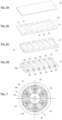
FIGURE 5 est un détail du porte-satellites de laFIGURE 4 , montrant une déformation de la cage réalisant une gorge selon un mode de réalisation, - les
FIGURES 6a, 6b, 6c et 6d sont des vues schématiques en perspective d'une plaque utilisée pour réaliser la cage d'un porte-satellites conforme à celui de laFIGURE 3 , chaque vue montrant le résultat d'une étape de fabrication, laFIGURE 6a montrant une plaque rectangulaire pleine et droite, laFIGURE 6b montrant la plaque de laFIGURE 6a présentant en outre des ouvertures réparties le long de celle-ci, laFIGURE 6c montrant la plaque de laFIGURE 6b présentant en outre une découpe d'accrochage à chaque extrémité longitudinale, laFIGURE 6d montrant la plaque de laFIGURE 6c présentant en outre des gorges agencées dans une direction transversale à la plaque, - la
FIGURE 7 est une vue axiale d'un train épicycloïdal incluant un porte-satellites selon l'invention dans une version à six satellites, les satellites coopérant à la fois avec une couronne dentée intérieurement et avec une roue dentée placée au centre du porte-satellites.
- there
FIGURE 1 is a view in longitudinal section of part of a mechanism of a brake actuator, including a planet carrier according to the prior art, - THE
FIGURES 2a and 2b are views of the planet carrier according to the prior art of theFIGURE 1 , thereFIGURE 2a being an axial view in slight perspective, theFIGURE 2b being a perspective view of a section of the planet carrier showing three of its satellites, - there
FIGURE 3 is a synthetic image seen in perspective of a planet carrier according to the invention, once assembled, in an exemplary embodiment carrying six satellites, - there
FIGURE 4 is a perspective and exploded view, or before assembly, of a planet carrier conforming to theFIGURE 3 , - there
FIGURE 5 is a detail of the satellite carrier of theFIGURE 4 , showing a deformation of the cage producing a groove according to one embodiment, - THE
FIGURES 6a, 6b, 6c and 6d are schematic perspective views of a plate used to make the cage of a planet carrier conforming to that of theFIGURE 3 , each view showing the result of a manufacturing step, theFIGURE 6a showing a solid and straight rectangular plate, theFIGURE 6b showing the plate of theFIGURE 6a further having openings distributed along the latter, theFIGURE 6c showing the plate of theFIGURE 6b further having a hooking cutout at each longitudinal end, theFIGURE 6d showing the plate of theFIGURE 6c further having grooves arranged in a direction transverse to the plate, - there
FIGURE 7 is an axial view of an epicyclic gear train including a planet carrier according to the invention in a version with six planet gears, the planet gears cooperating both with an internally toothed ring gear and with a toothed wheel placed in the center of the planet gear carrier.
Les
Cet ensemble forme par exemple une partie d'un train épicycloïdal à réduction différentielle, par exemple au sein d'un mécanisme similaire à celui de la
Selon le mode de réalisation préféré décrit par les
De manière avantageuse, l'armature est constituée d'une seule plaque 20 agencée et configurée pour former une enveloppe globalement cylindrique, de façon que l'armature présente la forme générale d'un tube circulaire, qui est entièrement débouchant à chacune de ses deux extrémités.Advantageously, the armature consists of a
L'armature présente des ouvertures 21 au travers desquelles des pignons satellites 30 font saillie radialement, du côté intérieur et du côté extérieur, voir
Optionnellement, par exemple dans le cas de satellites plus larges que long, ceux-ci peuvent ne comporter qu'un seul arbre dépassant d'une seule de ses faces transversales.Optionally, for example in the case of satellites that are wider than long, these may comprise only a single shaft projecting from a single one of its transverse faces.
Le ou les arbres sont par exemple venus de matière avec le satellite lors de sa fabrication, par exemple par moulage. Selon un autre exemple, ils sont formés par exemple par une ou des pièces préalables sur lesquelles est surmoulé le corps et la denture du satellite.The shaft or shafts are for example integral with the satellite during its manufacture, for example by molding. According to another example, they are formed for example by one or more preliminary parts on which the body and the teeth of the satellite are molded.
Optionnellement, le ou les arbres sont réalisés par des pièces séparées montées sur le satellite 31 avant ou après son montage dans la cage 10.Optionally, the shaft or shafts are made by separate parts mounted on the
L'armature forme des gorges longitudinales 25 dont la surface intérieure présente une section en arc de cercle, pour former un palier apte à supporter chacune un arbre de guidage en rotation dépassant d'un pignon satellite. Dans cet exemple, comme visible à la
De préférence, et en référence à la
Selon le mode de réalisation représenté aux
Selon un autre mode de réalisation non représenté, le passage des gorges débouchent radialement vers l'intérieur du porte-satellites, de façon que chaque pignon satellite 30 s'insère dans sa gorge par un mouvement qui l'écarte de l'axe de rotation A10 du porte-satellites. Chaque gorge fait alors saillie radialement en s'écartant de l'axe de rotation A10 du porte-satellites.According to another embodiment not shown, the passage of the grooves open radially towards the inside of the planet carrier, so that each
On va maintenant décrire, en référence aux
En référence à la
En référence à la
De préférence mais non obligatoirement, il est réalisé des formes ou des découpes d'accrochage 22, 23 à chaque extrémité de la plaque 20, des deux côtés de la succession d'ouvertures 21. Les découpes d'accrochage sont destinées à faire coopérer chaque extrémité l'une avec l'autre et les relier fixement, par exemple par coopération de formes complémentaires, après avoir cintrée la plaque pour former une enveloppe cylindrique. En référence à la
Alternativement, les deux extrémités de la plaque peuvent comporter des formes d'accrochages différentes. Elles peuvent aussi être solidarisées de façon différente, par exemple par soudure, sertissage, agrafage, ou par tout moyen connu.Alternatively, the two ends of the plate can have different hooking shapes. They can also be secured in different ways, for example by welding, crimping, stapling, or by any known means.
En référence à la
Par exemple après réalisation des ouvertures 21 et des gorges 25 réalisées, dans l'ordre énoncé ci-dessus ou dans un autre ordre, la plaque 20 est cintrée et/ou courbée de façon à former une enveloppe cylindrique autour de l'axe A10 qui sera celui du porte-satellites. Les extrémités de ladite plaque sont alors fixées entre elles, ici par emboîtement des queues d'aronde 22, 23 l'une dans l'autre de façon à relier fixement les deux extrémités de la plaque.For example, after making the
On va maintenant décrire un procédé d'assemblage d'un porte-satellites avec des satellites tels que décrits ci-dessus.We will now describe a method of assembling a planet carrier with satellites as described above.
A partir d'un porte-satellites tel que fabriqué selon le procédé ci-dessus, chaque pignon muni d'au moins un arbre de guidage en rotation et formant un satellite est introduit dans une ouverture, de façon à ce que ledit arbre de guidage en rotation soit dans une position coaxiale dans une gorge de l'armature.From a planet carrier as manufactured according to the above method, each pinion provided with at least one rotational guide shaft and forming a satellite is introduced into an opening, so that said guide shaft in rotation or in a coaxial position in a groove of the armature.
Selon un mode de réalisation des satellites, un arbre de guidage en rotation est inséré dans un alésage traversant agencé dans un pignon de façon que ledit arbre de guidage en rotation dépasse de part et d'autre du pignon. Dans ce mode de réalisation, l'arbre de guidage présente par exemple une longueur sensiblement égale à la longueur du pignon et de deux gorges.According to one embodiment of the satellites, a rotation guide shaft is inserted in a through bore arranged in a pinion so that said rotation guide shaft protrudes on either side of the pinion. In this embodiment, the guide shaft has for example a length substantially equal to the length of the pinion and of two grooves.
Selon un autre mode de réalisation des satellites, le pignon présente un alésage à chaque extrémité axiale, de façon à recevoir un arbre de guidage en rotation. Les arbres de rotation sont par exemple insérés par frettage.According to another embodiment of the satellites, the pinion has a bore at each axial end, so as to receive a rotating guide shaft. The rotation shafts are for example inserted by shrinking.
Encore selon un autre mode de réalisation, ces arbres sont intégrés au pignon avant montage. Ils sont par exemple venus de matière avec le pignon, ou forment une pièce rapportée autour de laquelle le pignon est réalisé par frittage ou surmoulage.Yet according to another embodiment, these shafts are integrated into the pinion before assembly. They are for example made in one piece with the pinion, or form an added part around which the pinion is produced by sintering or overmoulding.
Dans cet exemple, chaque gorge débouche radialement par un passage latéral, dont la largeur est inférieure au diamètre de l'arbre de guidage en rotation qu'elle reçoit, de façon que lors de l'étape d'introduction d'un satellite dans une gorge, ladite étape comprend une opération de clipsage de chaque arbre d'un pignon satellite dans chaque gorge.In this example, each groove emerges radially via a lateral passage, the width of which is less than the diameter of the drive shaft. rotational guidance that it receives, so that during the step of introducing a planet gear into a groove, said step comprises an operation of clipping each shaft of a planet gear into each groove.
Bien sûr, l'invention n'est pas limitée aux exemples qui viennent d'être décrits et de nombreux aménagements peuvent être apportés à ces exemples sans sortir du cadre de l'invention. Le cadre de l'invention est déterminé par les revendications.Of course, the invention is not limited to the examples which have just been described and many adjustments can be made to these examples without departing from the scope of the invention. The scope of the invention is determined by the claims.
- A16A16
- axe de l'actionneuractuator axis
- A140A140
- axe du porte-satellitesplanet carrier axis
- 111111
- pignon planétaire amontupstream planetary gear
- 119119
- extrémité d'entraînement de l'arbre d'entréeinput shaft drive end
- 121121
- denture de la couronne fixefixed crown teeth
- 130130
- porte-satellites amontupstream carrier
- 131131
- satellites du train épicycloïdal amontsatellites of the planetary gear train upstream
- 139139
- pignon planétaireplanetary gear
- 140140
- porte-satellitesplanet carrier
- 141141
- satellitessatellites
- 149149
- fenêtres longitudinales du porte-satellites différentiellongitudinal windows of the differential carrier
- 151151
- denture de la couronne mobiletoothing of the mobile crown
- 152152
- filetage de la visscrew thread
- 1616
- pièce formant écrou et piston de freinpart forming a nut and a brake piston
- 161161
- filetage intérieur de piston-écroupiston-nut internal thread
- A10A10
- axe du porte-satellites de DPRaxis of the DPR planet carrier
- A30A30
- axe d'un arbre de guidage d'un satellite de DPRaxis of a guide shaft of a DPR satellite
- 1010
- porte-satellites de DPRDPR planet carrier
- 1111
- pignon-roue planétaire centrale de DPRDPR Central Planetary Gear
- 1212
- couronne de DPRdpr crown
- 2020
- plaqueplaque
- 2121
- ouvertures longitudinales du porte-satellites de DPRlongitudinal openings of the DPR planet carrier
- 2222
- queue d'aronde contenantedovetail containing
- 2323
- queue d'aronde contenuecontained dovetail
- 2525
- gorgethroat
- 2727
- surface de réceptionlanding area
- 2626
- passagepassage
- 3030
- satellites de DPRDPR satellites
- 3131
- arbre de guidage de satellite de DPRDPR satellite guide shaft
Claims (14)
- Planet carrier (10) for an epicyclic gear train of a brake actuator, in particular a differential reduction brake actuator, for actuating a parking brake of a motor vehicle, which planet carrier comprises a framework arranged and configured in order to carry planet gears (30) distributed angularly about the axis (A10) of the planet carrier,characterized in that the framework comprises at least one plate (20) arranged and configured in order to form a cylindrical shell, said plate having openings (21) through which a planet gear (30) projects radially,and in that the plate (20) has a longitudinal groove (25) extending from at least one side of the openings, along a direction parallel to the axis of the planet carrier, so as to support one or more rotation-guiding shafts (31) protruding from said planet gears (30).
- Planet carrier (10) according to claim 1, characterized in that each groove (25) opens radially through a passage (26) the width of which is smaller than the diameter of the rotation-guiding shaft (31) that it receives so as to allow a radial clip-in insertion of said guide shaft.
- Planet carrier (10) according to claim 1 or 2, characterized in that the framework is arranged and configured in order to form only a cylindrical shell.
- Planet carrier (10) according to one of claims 1 to 3, characterized in that the framework consists of a single plate (20).
- Planet carrier (10) according to one of claims 1 to 4, characterized in that it is made of metallic material.
- Planet carrier (10) according to one of claims 1 to 4, characterized in that it is made of plastic material.
- Planet carrier (10) according to one of claims 1 to 6, characterized in that it comprises at least one planet gear (30).
- Planet carrier (10) according to claim 7, characterized in that the at least one planet gear (30) has at least two rotation-guiding shafts (31) on both sides of a toothed part of said gear, each rotation-guiding shaft being arranged and configured in order to be rotatably guided by a groove (25) of the framework of the planet carrier.
- Method for producing a planet carrier (10) according to any one of claims 1 to 8, comprising the following steps:- supplying a plate (20) of a determined length,- cutting portions at regular intervals, so as to form the openings (21) in order to receive the planets (30) in said plate,- shaping the plate (20) along a line passing through each opening, so as to form the groove or grooves (25) of said opening,- bending the plate (20) so as to form a cylindrical shell,- fixedly connecting the ends of the plate to each other.
- Method for producing a planet carrier (10) according to the preceding claim, further comprising the following steps:- cutting a first end of the plate so as to form a female dovetail (22) and cutting a second end of said plate, opposite the first, so as to form a male dovetail (23), said dovetails being arranged and configured in order to interlock with each other,- introducing the male dovetail (23) into the female dovetail (22), after having bent the plate (20) cylindrically, in order to join said ends.
- Method for producing a planet carrier (10) according to any one of claims 1 to 8, characterized in that the planet carrier is injection-moulded.
- Method for assembling a planet carrier (10) according to any one of claims 1 to 8, characterized in that it contains the steps consisting of:- creating the framework of the planet carrier,- introducing a gear (30) equipped with at least one rotation-guiding shaft (31) and forming a planet into the opening or openings (21) of the framework, in such a way that said rotation-guiding shaft is in a coaxial position in a groove (25) of the framework.
- Method for assembling according to the preceding claim, characterized in that each groove (25) opens radially through a passage (26) the width of which is smaller than the diameter of the rotation-guiding shaft (31) that it receives, in such a way that during the step of introducing a planet (30) into a groove (25), said step comprises an operation of clipping each shaft (31) of a planet gear into each groove (25).
- Brake actuator comprising a planet carrier (10) according to any one of claims 1 to 8.
Applications Claiming Priority (2)
| Application Number | Priority Date | Filing Date | Title |
|---|---|---|---|
| FR1761136A FR3074242B1 (en) | 2017-11-24 | 2017-11-24 | SATELLITE CARRIER FOR A DIFFERENTIALLY REDUCED BRAKE ACTUATOR AND METHOD OF MANUFACTURING THE SATELLITE HOLDER |
| PCT/EP2018/082076 WO2019101792A1 (en) | 2017-11-24 | 2018-11-21 | Planet carrier for differential reduction brake actuator and method for manufacturing said planet carrier |
Publications (2)
| Publication Number | Publication Date |
|---|---|
| EP3714182A1 EP3714182A1 (en) | 2020-09-30 |
| EP3714182B1 true EP3714182B1 (en) | 2023-04-19 |
Family
ID=61132631
Family Applications (1)
| Application Number | Title | Priority Date | Filing Date |
|---|---|---|---|
| EP18814498.4A Active EP3714182B1 (en) | 2017-11-24 | 2018-11-21 | Satellite gear carrier for for a brake reduction gear, and method for manufacturing such satellite gear carrier |
Country Status (3)
| Country | Link |
|---|---|
| EP (1) | EP3714182B1 (en) |
| FR (1) | FR3074242B1 (en) |
| WO (1) | WO2019101792A1 (en) |
Families Citing this family (2)
| Publication number | Priority date | Publication date | Assignee | Title |
|---|---|---|---|---|
| DE102018133388B4 (en) * | 2018-12-21 | 2022-03-03 | Rolls-Royce Deutschland Ltd & Co Kg | Planetary gear and method of assembling a planetary gear |
| FR3097023B1 (en) * | 2019-06-04 | 2021-06-25 | Foundation Brakes France | Planetary gearbox comprising at least one axial force transmission part forming a radially eccentric force path |
Family Cites Families (3)
| Publication number | Priority date | Publication date | Assignee | Title |
|---|---|---|---|---|
| JP2008002603A (en) * | 2006-06-23 | 2008-01-10 | Unipres Corp | Planetary gear mechanism carrier plate and carrier assembly |
| DE102011087078A1 (en) * | 2011-11-25 | 2013-05-29 | Schaeffler Technologies AG & Co. KG | Planet carrier for use in gear i.e. planetary gear, utilized in differential generator, has supporting plate arranged parallel to another supporting plate and comprising connecting link that is radially welded with latter plate |
| FR3031154B1 (en) * | 2014-12-29 | 2018-04-27 | Foundation Brakes France | DIFFERENTIALLY REDUCING BRAKE ACTUATOR, BRAKE OR BRAKE CALIPER INCLUDING SUCH ACTUATOR, AND METHOD FOR LOOSENING SUCH BRAKE |
-
2017
- 2017-11-24 FR FR1761136A patent/FR3074242B1/en active Active
-
2018
- 2018-11-21 EP EP18814498.4A patent/EP3714182B1/en active Active
- 2018-11-21 WO PCT/EP2018/082076 patent/WO2019101792A1/en unknown
Also Published As
| Publication number | Publication date |
|---|---|
| WO2019101792A1 (en) | 2019-05-31 |
| EP3714182A1 (en) | 2020-09-30 |
| FR3074242B1 (en) | 2019-11-01 |
| FR3074242A1 (en) | 2019-05-31 |
Similar Documents
| Publication | Publication Date | Title |
|---|---|---|
| EP2935945B1 (en) | Planet carrier for an electromechanical actuator of a parking brake, actuator and assembly methods | |
| EP3089901B1 (en) | Motor-reducer with planetary gearset, drum and disc brake and braking device provided with same | |
| EP3240964B1 (en) | Differential reduction brake actuator, brake or brake caliper including such an actuator, and method for releasing such a brake | |
| EP3714182B1 (en) | Satellite gear carrier for for a brake reduction gear, and method for manufacturing such satellite gear carrier | |
| FR3029874A1 (en) | ELECTRICAL ACTUATOR FOR PARKING BRAKE LEVER WITH DRUM BRAKE | |
| FR3017174A1 (en) | TRANSMISSION DEVICE FOR CONTROLLING THE ORGANIZATION TRANSLATION MOTION AND BRAKE SYSTEM EQUIPPED WITH SUCH A TRANSMISSION DEVICE FORMING A SERVOFREIN | |
| EP3175136B1 (en) | Vehicle brake actuator | |
| FR2741415A1 (en) | COMPACT REDUCER WITH TWO STAGES OF REDUCTION | |
| FR3091244A1 (en) | GEAR MOTOR FOR DRUM BRAKE PROVIDING IMPORTANT CONFORMABILITY | |
| WO2015101484A2 (en) | Drum brake device suitable for including a parking brake that is conventional or that operates in duo servo mode | |
| FR2573700A1 (en) | HUB BODY FOR BICYCLE WHEEL DRIVE OR THE LIKE, AND METHOD FOR MANUFACTURING THE SAME | |
| EP3089900B1 (en) | Motor-reducer with electric motor for drum brake actuator | |
| FR2734616A1 (en) | MULTIPLE DISC FRICTION CLUTCH HAVING AN AXIAL STOP | |
| FR2827202A1 (en) | Formation of retaining collar especially for wheel hub bearing uses two tools to deform and deploy hub end | |
| EP2551541B1 (en) | Method for assembling a clamp around an outer ring of a bearing | |
| WO2019101793A1 (en) | Gear mechanism for brake actuator with differential reduction, and assembly method | |
| EP3240710B1 (en) | Linear actuator, disc-brake actuator, method of manufacturing an internal toothset | |
| FR2992391A1 (en) | SCREW DRIVE SYSTEM, IN PARTICULAR FOR AN IMMOBILISATION BRAKE | |
| EP3963234B1 (en) | Epicyclic step-down gear comprising at least one axial force transmission component which forms a radially eccentric force path | |
| FR3018328A3 (en) | DIFFERENTIAL FOR MOTOR VEHICLE WITH HOLDING DEVICE IN THE POSITION OF THE AXLE SATELLITE | |
| FR3148064A1 (en) | ELECTROMECHANICAL DISC BRAKE WITH INCREASED COMPACTNESS | |
| WO2020244936A1 (en) | Gear motor for drum brake actuator, comprising a step-down rate of 30 to 210 | |
| EP1317355A1 (en) | Method for fixing at least a guiding insert between two coaxial tubes, in particular in a motor vehicle anti-roll device | |
| FR3091322A1 (en) | METHOD OF DESIGNING A MOTOR-REDUCER ADAPTED TO A PARTICULAR SIZE | |
| FR3095487A1 (en) | SATELLITE SCREW MECHANISM |
Legal Events
| Date | Code | Title | Description |
|---|---|---|---|
| STAA | Information on the status of an ep patent application or granted ep patent |
Free format text: STATUS: UNKNOWN |
|
| STAA | Information on the status of an ep patent application or granted ep patent |
Free format text: STATUS: THE INTERNATIONAL PUBLICATION HAS BEEN MADE |
|
| PUAI | Public reference made under article 153(3) epc to a published international application that has entered the european phase |
Free format text: ORIGINAL CODE: 0009012 |
|
| STAA | Information on the status of an ep patent application or granted ep patent |
Free format text: STATUS: REQUEST FOR EXAMINATION WAS MADE |
|
| 17P | Request for examination filed |
Effective date: 20200610 |
|
| AK | Designated contracting states |
Kind code of ref document: A1 Designated state(s): AL AT BE BG CH CY CZ DE DK EE ES FI FR GB GR HR HU IE IS IT LI LT LU LV MC MK MT NL NO PL PT RO RS SE SI SK SM TR |
|
| AX | Request for extension of the european patent |
Extension state: BA ME |
|
| DAV | Request for validation of the european patent (deleted) | ||
| DAX | Request for extension of the european patent (deleted) | ||
| GRAP | Despatch of communication of intention to grant a patent |
Free format text: ORIGINAL CODE: EPIDOSNIGR1 |
|
| STAA | Information on the status of an ep patent application or granted ep patent |
Free format text: STATUS: GRANT OF PATENT IS INTENDED |
|
| INTG | Intention to grant announced |
Effective date: 20221117 |
|
| RIN1 | Information on inventor provided before grant (corrected) |
Inventor name: CUBIZOLLES, CYRIL Inventor name: BOURLON, PHILIPPE |
|
| GRAS | Grant fee paid |
Free format text: ORIGINAL CODE: EPIDOSNIGR3 |
|
| GRAA | (expected) grant |
Free format text: ORIGINAL CODE: 0009210 |
|
| STAA | Information on the status of an ep patent application or granted ep patent |
Free format text: STATUS: THE PATENT HAS BEEN GRANTED |
|
| AK | Designated contracting states |
Kind code of ref document: B1 Designated state(s): AL AT BE BG CH CY CZ DE DK EE ES FI FR GB GR HR HU IE IS IT LI LT LU LV MC MK MT NL NO PL PT RO RS SE SI SK SM TR |
|
| REG | Reference to a national code |
Ref country code: GB Ref legal event code: FG4D Free format text: NOT ENGLISH |
|
| REG | Reference to a national code |
Ref country code: CH Ref legal event code: EP |
|
| REG | Reference to a national code |
Ref country code: DE Ref legal event code: R096 Ref document number: 602018048667 Country of ref document: DE |
|
| REG | Reference to a national code |
Ref country code: IE Ref legal event code: FG4D Free format text: LANGUAGE OF EP DOCUMENT: FRENCH |
|
| REG | Reference to a national code |
Ref country code: AT Ref legal event code: REF Ref document number: 1561405 Country of ref document: AT Kind code of ref document: T Effective date: 20230515 |
|
| REG | Reference to a national code |
Ref country code: LT Ref legal event code: MG9D |
|
| REG | Reference to a national code |
Ref country code: NL Ref legal event code: MP Effective date: 20230419 |
|
| REG | Reference to a national code |
Ref country code: AT Ref legal event code: MK05 Ref document number: 1561405 Country of ref document: AT Kind code of ref document: T Effective date: 20230419 |
|
| PG25 | Lapsed in a contracting state [announced via postgrant information from national office to epo] |
Ref country code: NL Free format text: LAPSE BECAUSE OF FAILURE TO SUBMIT A TRANSLATION OF THE DESCRIPTION OR TO PAY THE FEE WITHIN THE PRESCRIBED TIME-LIMIT Effective date: 20230419 |
|
| PG25 | Lapsed in a contracting state [announced via postgrant information from national office to epo] |
Ref country code: SE Free format text: LAPSE BECAUSE OF FAILURE TO SUBMIT A TRANSLATION OF THE DESCRIPTION OR TO PAY THE FEE WITHIN THE PRESCRIBED TIME-LIMIT Effective date: 20230419 Ref country code: PT Free format text: LAPSE BECAUSE OF FAILURE TO SUBMIT A TRANSLATION OF THE DESCRIPTION OR TO PAY THE FEE WITHIN THE PRESCRIBED TIME-LIMIT Effective date: 20230821 Ref country code: NO Free format text: LAPSE BECAUSE OF FAILURE TO SUBMIT A TRANSLATION OF THE DESCRIPTION OR TO PAY THE FEE WITHIN THE PRESCRIBED TIME-LIMIT Effective date: 20230719 Ref country code: ES Free format text: LAPSE BECAUSE OF FAILURE TO SUBMIT A TRANSLATION OF THE DESCRIPTION OR TO PAY THE FEE WITHIN THE PRESCRIBED TIME-LIMIT Effective date: 20230419 Ref country code: AT Free format text: LAPSE BECAUSE OF FAILURE TO SUBMIT A TRANSLATION OF THE DESCRIPTION OR TO PAY THE FEE WITHIN THE PRESCRIBED TIME-LIMIT Effective date: 20230419 |
|
| PG25 | Lapsed in a contracting state [announced via postgrant information from national office to epo] |
Ref country code: RS Free format text: LAPSE BECAUSE OF FAILURE TO SUBMIT A TRANSLATION OF THE DESCRIPTION OR TO PAY THE FEE WITHIN THE PRESCRIBED TIME-LIMIT Effective date: 20230419 Ref country code: PL Free format text: LAPSE BECAUSE OF FAILURE TO SUBMIT A TRANSLATION OF THE DESCRIPTION OR TO PAY THE FEE WITHIN THE PRESCRIBED TIME-LIMIT Effective date: 20230419 Ref country code: LV Free format text: LAPSE BECAUSE OF FAILURE TO SUBMIT A TRANSLATION OF THE DESCRIPTION OR TO PAY THE FEE WITHIN THE PRESCRIBED TIME-LIMIT Effective date: 20230419 Ref country code: LT Free format text: LAPSE BECAUSE OF FAILURE TO SUBMIT A TRANSLATION OF THE DESCRIPTION OR TO PAY THE FEE WITHIN THE PRESCRIBED TIME-LIMIT Effective date: 20230419 Ref country code: IS Free format text: LAPSE BECAUSE OF FAILURE TO SUBMIT A TRANSLATION OF THE DESCRIPTION OR TO PAY THE FEE WITHIN THE PRESCRIBED TIME-LIMIT Effective date: 20230819 Ref country code: HR Free format text: LAPSE BECAUSE OF FAILURE TO SUBMIT A TRANSLATION OF THE DESCRIPTION OR TO PAY THE FEE WITHIN THE PRESCRIBED TIME-LIMIT Effective date: 20230419 Ref country code: GR Free format text: LAPSE BECAUSE OF FAILURE TO SUBMIT A TRANSLATION OF THE DESCRIPTION OR TO PAY THE FEE WITHIN THE PRESCRIBED TIME-LIMIT Effective date: 20230720 Ref country code: AL Free format text: LAPSE BECAUSE OF FAILURE TO SUBMIT A TRANSLATION OF THE DESCRIPTION OR TO PAY THE FEE WITHIN THE PRESCRIBED TIME-LIMIT Effective date: 20230419 |
|
| PG25 | Lapsed in a contracting state [announced via postgrant information from national office to epo] |
Ref country code: FI Free format text: LAPSE BECAUSE OF FAILURE TO SUBMIT A TRANSLATION OF THE DESCRIPTION OR TO PAY THE FEE WITHIN THE PRESCRIBED TIME-LIMIT Effective date: 20230419 |
|
| PG25 | Lapsed in a contracting state [announced via postgrant information from national office to epo] |
Ref country code: SK Free format text: LAPSE BECAUSE OF FAILURE TO SUBMIT A TRANSLATION OF THE DESCRIPTION OR TO PAY THE FEE WITHIN THE PRESCRIBED TIME-LIMIT Effective date: 20230419 |
|
| REG | Reference to a national code |
Ref country code: DE Ref legal event code: R097 Ref document number: 602018048667 Country of ref document: DE |
|
| PG25 | Lapsed in a contracting state [announced via postgrant information from national office to epo] |
Ref country code: SM Free format text: LAPSE BECAUSE OF FAILURE TO SUBMIT A TRANSLATION OF THE DESCRIPTION OR TO PAY THE FEE WITHIN THE PRESCRIBED TIME-LIMIT Effective date: 20230419 Ref country code: SK Free format text: LAPSE BECAUSE OF FAILURE TO SUBMIT A TRANSLATION OF THE DESCRIPTION OR TO PAY THE FEE WITHIN THE PRESCRIBED TIME-LIMIT Effective date: 20230419 Ref country code: RO Free format text: LAPSE BECAUSE OF FAILURE TO SUBMIT A TRANSLATION OF THE DESCRIPTION OR TO PAY THE FEE WITHIN THE PRESCRIBED TIME-LIMIT Effective date: 20230419 Ref country code: EE Free format text: LAPSE BECAUSE OF FAILURE TO SUBMIT A TRANSLATION OF THE DESCRIPTION OR TO PAY THE FEE WITHIN THE PRESCRIBED TIME-LIMIT Effective date: 20230419 Ref country code: DK Free format text: LAPSE BECAUSE OF FAILURE TO SUBMIT A TRANSLATION OF THE DESCRIPTION OR TO PAY THE FEE WITHIN THE PRESCRIBED TIME-LIMIT Effective date: 20230419 Ref country code: CZ Free format text: LAPSE BECAUSE OF FAILURE TO SUBMIT A TRANSLATION OF THE DESCRIPTION OR TO PAY THE FEE WITHIN THE PRESCRIBED TIME-LIMIT Effective date: 20230419 |
|
| PGFP | Annual fee paid to national office [announced via postgrant information from national office to epo] |
Ref country code: FR Payment date: 20231019 Year of fee payment: 6 Ref country code: DE Payment date: 20231019 Year of fee payment: 6 |
|
| PLBE | No opposition filed within time limit |
Free format text: ORIGINAL CODE: 0009261 |
|
| STAA | Information on the status of an ep patent application or granted ep patent |
Free format text: STATUS: NO OPPOSITION FILED WITHIN TIME LIMIT |
|
| 26N | No opposition filed |
Effective date: 20240122 |
|
| PG25 | Lapsed in a contracting state [announced via postgrant information from national office to epo] |
Ref country code: SI Free format text: LAPSE BECAUSE OF FAILURE TO SUBMIT A TRANSLATION OF THE DESCRIPTION OR TO PAY THE FEE WITHIN THE PRESCRIBED TIME-LIMIT Effective date: 20230419 |
|
| PG25 | Lapsed in a contracting state [announced via postgrant information from national office to epo] |
Ref country code: SI Free format text: LAPSE BECAUSE OF FAILURE TO SUBMIT A TRANSLATION OF THE DESCRIPTION OR TO PAY THE FEE WITHIN THE PRESCRIBED TIME-LIMIT Effective date: 20230419 Ref country code: IT Free format text: LAPSE BECAUSE OF FAILURE TO SUBMIT A TRANSLATION OF THE DESCRIPTION OR TO PAY THE FEE WITHIN THE PRESCRIBED TIME-LIMIT Effective date: 20230419 |
|
| REG | Reference to a national code |
Ref country code: CH Ref legal event code: PL |
|
| PG25 | Lapsed in a contracting state [announced via postgrant information from national office to epo] |
Ref country code: MC Free format text: LAPSE BECAUSE OF FAILURE TO SUBMIT A TRANSLATION OF THE DESCRIPTION OR TO PAY THE FEE WITHIN THE PRESCRIBED TIME-LIMIT Effective date: 20230419 |
|
| PG25 | Lapsed in a contracting state [announced via postgrant information from national office to epo] |
Ref country code: LU Free format text: LAPSE BECAUSE OF NON-PAYMENT OF DUE FEES Effective date: 20231121 |
|
| PG25 | Lapsed in a contracting state [announced via postgrant information from national office to epo] |
Ref country code: CH Free format text: LAPSE BECAUSE OF NON-PAYMENT OF DUE FEES Effective date: 20231130 |
|
| GBPC | Gb: european patent ceased through non-payment of renewal fee |
Effective date: 20231121 |
|
| PG25 | Lapsed in a contracting state [announced via postgrant information from national office to epo] |
Ref country code: MC Free format text: LAPSE BECAUSE OF FAILURE TO SUBMIT A TRANSLATION OF THE DESCRIPTION OR TO PAY THE FEE WITHIN THE PRESCRIBED TIME-LIMIT Effective date: 20230419 Ref country code: LU Free format text: LAPSE BECAUSE OF NON-PAYMENT OF DUE FEES Effective date: 20231121 Ref country code: CH Free format text: LAPSE BECAUSE OF NON-PAYMENT OF DUE FEES Effective date: 20231130 |
|
| REG | Reference to a national code |
Ref country code: BE Ref legal event code: MM Effective date: 20231130 |
|
| REG | Reference to a national code |
Ref country code: IE Ref legal event code: MM4A |
|
| PG25 | Lapsed in a contracting state [announced via postgrant information from national office to epo] |
Ref country code: IE Free format text: LAPSE BECAUSE OF NON-PAYMENT OF DUE FEES Effective date: 20231121 |
|
| PG25 | Lapsed in a contracting state [announced via postgrant information from national office to epo] |
Ref country code: GB Free format text: LAPSE BECAUSE OF NON-PAYMENT OF DUE FEES Effective date: 20231121 |
|
| PG25 | Lapsed in a contracting state [announced via postgrant information from national office to epo] |
Ref country code: BE Free format text: LAPSE BECAUSE OF NON-PAYMENT OF DUE FEES Effective date: 20231130 |