EP3714182B1 - Planetzahnradträger einer bremse eines planetengetriebes, und herstellungsverfahren so ein planetenzahnradträger - Google Patents
Planetzahnradträger einer bremse eines planetengetriebes, und herstellungsverfahren so ein planetenzahnradträger Download PDFInfo
- Publication number
- EP3714182B1 EP3714182B1 EP18814498.4A EP18814498A EP3714182B1 EP 3714182 B1 EP3714182 B1 EP 3714182B1 EP 18814498 A EP18814498 A EP 18814498A EP 3714182 B1 EP3714182 B1 EP 3714182B1
- Authority
- EP
- European Patent Office
- Prior art keywords
- planet carrier
- plate
- planet
- groove
- rotation
- Prior art date
- Legal status (The legal status is an assumption and is not a legal conclusion. Google has not performed a legal analysis and makes no representation as to the accuracy of the status listed.)
- Active
Links
- 238000004519 manufacturing process Methods 0.000 title claims description 25
- 230000009467 reduction Effects 0.000 title claims description 10
- 238000000034 method Methods 0.000 title claims description 8
- 238000005520 cutting process Methods 0.000 claims description 6
- 239000004033 plastic Substances 0.000 claims description 6
- 239000000463 material Substances 0.000 claims description 5
- 238000005452 bending Methods 0.000 claims description 4
- 238000003780 insertion Methods 0.000 claims description 4
- 230000037431 insertion Effects 0.000 claims description 4
- 239000007769 metal material Substances 0.000 claims description 2
- 238000007493 shaping process Methods 0.000 claims description 2
- 238000011144 upstream manufacturing Methods 0.000 description 8
- 230000007246 mechanism Effects 0.000 description 5
- 230000008878 coupling Effects 0.000 description 4
- 238000010168 coupling process Methods 0.000 description 4
- 238000005859 coupling reaction Methods 0.000 description 4
- 238000004080 punching Methods 0.000 description 3
- 230000008901 benefit Effects 0.000 description 2
- 238000002347 injection Methods 0.000 description 2
- 239000007924 injection Substances 0.000 description 2
- 238000000465 moulding Methods 0.000 description 2
- 230000008569 process Effects 0.000 description 2
- 230000002787 reinforcement Effects 0.000 description 2
- 230000000712 assembly Effects 0.000 description 1
- 238000000429 assembly Methods 0.000 description 1
- 230000004323 axial length Effects 0.000 description 1
- 230000005540 biological transmission Effects 0.000 description 1
- 230000015572 biosynthetic process Effects 0.000 description 1
- 239000000969 carrier Substances 0.000 description 1
- 230000008859 change Effects 0.000 description 1
- 239000003638 chemical reducing agent Substances 0.000 description 1
- 230000000295 complement effect Effects 0.000 description 1
- 238000002788 crimping Methods 0.000 description 1
- 239000002184 metal Substances 0.000 description 1
- 239000011347 resin Substances 0.000 description 1
- 229920005989 resin Polymers 0.000 description 1
- 238000007789 sealing Methods 0.000 description 1
- 238000005245 sintering Methods 0.000 description 1
- 239000007787 solid Substances 0.000 description 1
- 239000000126 substance Substances 0.000 description 1
- 229920001169 thermoplastic Polymers 0.000 description 1
- 229920001187 thermosetting polymer Polymers 0.000 description 1
- 239000004416 thermosoftening plastic Substances 0.000 description 1
- 238000003466 welding Methods 0.000 description 1
Images

Classifications
-
- F—MECHANICAL ENGINEERING; LIGHTING; HEATING; WEAPONS; BLASTING
- F16—ENGINEERING ELEMENTS AND UNITS; GENERAL MEASURES FOR PRODUCING AND MAINTAINING EFFECTIVE FUNCTIONING OF MACHINES OR INSTALLATIONS; THERMAL INSULATION IN GENERAL
- F16D—COUPLINGS FOR TRANSMITTING ROTATION; CLUTCHES; BRAKES
- F16D65/00—Parts or details
- F16D65/14—Actuating mechanisms for brakes; Means for initiating operation at a predetermined position
-
- F—MECHANICAL ENGINEERING; LIGHTING; HEATING; WEAPONS; BLASTING
- F16—ENGINEERING ELEMENTS AND UNITS; GENERAL MEASURES FOR PRODUCING AND MAINTAINING EFFECTIVE FUNCTIONING OF MACHINES OR INSTALLATIONS; THERMAL INSULATION IN GENERAL
- F16H—GEARING
- F16H57/00—General details of gearing
- F16H57/08—General details of gearing of gearings with members having orbital motion
- F16H57/082—Planet carriers
-
- F—MECHANICAL ENGINEERING; LIGHTING; HEATING; WEAPONS; BLASTING
- F16—ENGINEERING ELEMENTS AND UNITS; GENERAL MEASURES FOR PRODUCING AND MAINTAINING EFFECTIVE FUNCTIONING OF MACHINES OR INSTALLATIONS; THERMAL INSULATION IN GENERAL
- F16D—COUPLINGS FOR TRANSMITTING ROTATION; CLUTCHES; BRAKES
- F16D2125/00—Components of actuators
- F16D2125/18—Mechanical mechanisms
- F16D2125/44—Mechanical mechanisms transmitting rotation
- F16D2125/46—Rotating members in mutual engagement
- F16D2125/50—Rotating members in mutual engagement with parallel non-stationary axes, e.g. planetary gearing
Definitions
- the present invention relates to a planet carrier for a differential reduction brake actuator and to a method of manufacturing a planet carrier.
- the field of the invention is that of braking systems for automobiles.
- the invention proposes a planet carrier comprising a frame arranged and configured to carry planet gears distributed angularly around the axis of the planet carrier.
- the armature comprises a single plate arranged and configured to form a cylindrical casing which has openings through which a planet pinion projects radially.
- the plate has a deformation producing a longitudinal groove on at least one side of the openings, along a direction parallel to the axis of the planet carrier, so as to support one or more rotational guide shafts projecting from said planet pinions .
- the parking and/or emergency brake function consists in applying and maintaining a tightening of brake pads linked to a part integral with the chassis, on a rotating mobile part which is linked to one or several wheels, typically a disc or a drum.
- the screw-nut system is operated by a gear motor.
- Some gear reduction mechanisms include one or more planetary gear sets.
- An epicyclic gear train comprises two sun gears (a first sun gear, called inner, and a second sun gear, called outer) and satellites carried by a planet carrier. Each satellite meshes simultaneously with the two sun gears which are arranged coaxially.
- the outer sun gear is internally toothed, and is often referred to as the "crown”.
- the inner planetary is often referred to simply as "the planetary”, without further precision.
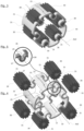
- the document FR 3 031 154 A1 discloses a reducer which includes two stages of reduction. With reference to the Figure 1 , it comprises an upstream reduction stage formed by an upstream planetary gear train with satellites 131 and fixed ring gear 121. This upstream gear is driven at the input by its inner sun gear 111, itself driven by a toothed shaft bearing a drive cavity 119 This upstream planetary gear train drives its planet carrier 130 on its output.
- the second stage comprises an epicyclic gear train driven at the input by the sun gear 139, and whose satellites 141 mesh with a fixed ring gear 121, here the same as for the upstream epicyclic gear train.
- this movable crown 151 carries a thread 152 coaxial with the epicyclic trains, and cooperating with an internal thread 161 of the piston 16 for the drive in translation.
- the fixed crown 121 is common to the two planetary gear sets, and the differential satellites 141 are common to the two crowns 121, 151 of the differential gear set, which generally carry a different number of teeth from one to the other.
- the planet carrier is generally machined or sintered or even molded, in metal or plastic.
- the planet carrier comprises a frame of simply tubular or approximately general shape and open at its axial ends.
- the armature of the planet carrier 140 has the shape of a tube, the thickness of the wall of which is such that the wall encompasses the rotation shaft of each satellite.
- the planet carrier is machined radially along its circumference so as to produce several windows 149, of substantially rectangular shape, each window being provided to receive a satellite. Each window is delimited longitudinally at each end by a support part of the tube forming a rotation support for each satellite.
- a bore is machined on each transverse face of a support part to receive a rotation shaft of a satellite.
- the planet carrier forms a cage for the satellites.
- Each support part forming a transverse flange for each satellite end and the satellites protrude radially from the circumference of the planet carrier.
- Each guide shaft is crimped in a bore of the planet carrier, each satellite being mounted freely in rotation on a guide shaft.
- Each satellite has a through longitudinal bore, which opens onto each transverse face and is arranged and configured to receive a guide shaft.
- An object of the invention is to propose a planet carrier making it possible to facilitate the mounting of the satellites on the planet carrier.
- Another object of the invention is to propose a method of manufacturing said planet carrier in order to lower its manufacturing cost.
- the invention proposes a planet carrier of the type without an input or output coupling shaft, and more particularly a planet carrier for an epicyclic gear train of a differential reduction brake actuator for actuation of a motor vehicle parking brake.
- the planet carrier comprises a frame arranged and configured to carry planet pinions distributed angularly around the axis of the planet carrier.
- the satellite pinions are angularly distributed in a regular manner along the frame.
- the armature comprises at least one plate arranged and configured to form a cylindrical casing, said plate having openings through which a planet pinion projects radially.
- it is a plate forming a piece unique coming of material, and for example a single plate.
- the plate has a succession of longitudinal grooves, extending from at least one side of the openings along a direction parallel to the axis of the planet carrier, so as to support one or more rotational guide shafts projecting from said satellite gears.
- this groove is made by a part of the plate which is deformed into an arc of a circle, typically without modifying its thickness, around the axis of this arc of a circle.
- This deformation is for example carried out by plastic deformation, for example by stamping or stamping, for example simultaneously with the cutting of the openings or in the same series of operations carried out successively in an automated manner under a press.
- this groove can also be produced by other processes modifying the thickness of the plate at this location, for example by punching and/or by removing material.
- a planet carrier according to the invention facilitates the operation of mounting the planet gears on the planet carrier, and facilitates its manufacture, and thus lowers its manufacturing cost.
- the term “plate” is understood here to mean a part that is thin along one dimension with respect to its other dimensions, for example by at most 10%, and typically of a substantially constant thickness, for example to within 20%.
- the armature plate has a constant thickness along the circumference of the armature.
- the plate, at the level of each groove, has for example a constant thickness, equal to the rest of the reinforcement, for example with a tolerance of plus or minus 20% (twenty percent).
- Each groove makes it possible to produce a rotation bearing to guide in rotation a guide shaft of a planet pinion.
- a longitudinal groove is provided on each side of the openings along a direction parallel to the axis of the planet carrier, so as to support one or more rotational guide shafts projecting from said planet pinions.
- Each groove opens radially through a passage whose width is less than the diameter of the rotating guide shaft that it receives, so as to allow insertion by radial clipping of said guide shaft.
- This characteristic makes it possible to hold each satellite pinion in position in a groove.
- This characteristic is particularly advantageous for facilitating the mounting of the planet carrier in an actuator, once provided with the planet gears.
- the groove is produced for example according to one of the following two embodiments.
- the deformation of the plate forming the groove is such that it extends towards the inside of the planet carrier in a direction radial to the axis of rotation of the planet carrier, that is to say say while approaching the axis of rotation; the opening of the groove then opening out towards the outside of the planet carrier.
- the deformation of the plate forming the groove is such that it extends outwards in a direction radial to the axis of rotation of the planet carrier, that is to say in s' moving away from the axis of rotation, the opening of the groove then opening out towards the inside of the planet carrier.
- the armature is arranged and configured to form only a cylindrical casing, with no torque transmission element from the planet carrier to other mechanical elements.
- the cylindrical casing substantially forms a tube, opening out at each axial end without a sealing flange. It can consist of one or more plates. These characteristics facilitate the manufacture of the planet carrier.
- the reinforcement consists of a single plate, forming the entire periphery of the cage and/or over a single thickness. This characteristic facilitates the manufacture and assembly of a planet carrier and thus lowers the cost of manufacture.
- the planet carrier is made of metallic material or of plastic material.
- the planet carrier made of plastic material is for example produced by molding, for example using a thermal process such as injection of thermoplastic or thermosetting plastic, and/or of a chemical resin.
- the planet carrier comprises at least one planet pinion.
- the at least one satellite pinion has one or at least two rotation guide shafts.
- each shaft is placed in a bore made on either side of a planet pinion, the two bores being coaxial.
- Each shaft is designed to project axially on either side of a toothed portion of the pinion.
- each rotation guide shaft is arranged and configured to be guided in rotation by a groove in the frame of the planet carrier.
- the planet carrier and planet gear assembly thus proposed has the advantage of being easier to manufacture and to assemble, thus making it possible to lower its manufacturing cost.
- the axial length of the satellites is between 2 mm and 50 mm, preferably between 5 and 30 mm, more preferably between 15 and 25 mm, for example equal to 19 mm, or 20 mm or 21 mm.
- the diameter of the satellites is between 2 mm and 40 mm, preferably between 4 and 30 mm, more preferably between 6 and 20 mm, for example equal to 9 mm, or 10 mm or 11 mm.
- the plate can be cut from a larger plate, for example from a roll.
- the portions to be cut are rectangular. They are for example made by stamping or stamping.
- the formation of the grooves is for example carried out by punching, stamping, stamping or stamping.
- the step of bending the plate can be carried out by bending.
- the manufacturing method according to the invention thus makes it possible to lower the manufacturing cost of a planet carrier.
- a fourth aspect of the invention which is in accordance with one of the first two aspects or with the first two aspects, there is proposed a method of manufacturing a planet carrier characterized in that the planet carrier is molded by injection.
- each groove opens out radially through a passage whose width is less than the diameter of the rotation guide shaft that it receives, so that during the step of introducing a satellite into a groove, said step includes an operation of clipping each shaft of a planet gear into each groove.
- each guide shaft is moved in a substantially radial direction with respect to the axis of rotation of the planet carrier to be inserted into a groove, either by moving away from the axis of rotation, or approaching the axis of rotation according to the conformation of the deformations forming the grooves.
- a brake actuator comprising a planet carrier.
- FIGURES 3 and 4 illustrate a planet carrier 10 of the type without a coupling shaft or without a coupling part between the planet carrier and a rotating shaft.
- the planet carrier is intended to cooperate with only satellite pinions 30, that is to say that the rotation of the cage does not transmit any significant force to any other mechanical element of the mechanism, or any force entering the dynamic chain of actuation.
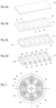
- FIGURE 7 illustrates such a planet carrier 10, said without coupling part, forming part of a planetary gear train with differential reduction within a brake actuator, for example for actuating a motor vehicle parking brake.
- the planet carrier 10, carrying the planet pinions 30, is inserted between a central sun gear 11 and an internally toothed crown 12; the three elements being arranged coaxially with respect to the axis of rotation A10. Only the planet pinions 30 are in simultaneous contact with the pinion 11 and the crown 12.
- Each planet pinion 30 is carried by the planet carrier 10, by means of one or two rotation guide shafts 31 around a axis of rotation A30.
- This assembly forms for example part of a planetary gear train with differential reduction, for example within a mechanism similar to that of the FIGURE 1 .
- the planet carrier 10 and its planets 30 according to the invention can for example replace the planet carrier 140 and the planets 141 of the FIGURES 1, 2a and 2b .
- the planet carrier 10 forms a frame arranged and configured to carry planet pinions 30 distributed angularly around the axis A10 of the planet carrier and along the frame.
- the satellite pinions 30 are here distributed angularly in a regular manner along said frame.
- the armature consists of a single plate 20 arranged and configured to form a generally cylindrical envelope, so that the armature has the general shape of a circular tube, which is entirely open at each of its two ends.
- the frame has openings 21 through which satellite pinions 30 protrude radially, on the inside and on the outside, see FIGURE 3 .
- the openings 21 are made in the plate 20 so as to each be able to receive a planet pinion, typically only one per opening.
- the openings 21 are of the shape rectangular.
- the openings 21 extend mainly in a direction parallel to the axis of rotation A10 of the planet carrier, and receive elongated satellites along their axis of rotation. These satellites each carry two shafts 31 protruding from the two opposite transverse faces.
- the openings extend mainly in a direction perpendicular to the axis of rotation A10 of the planet carrier, possibly but not necessarily to receive satellites of a larger diameter than along their axis rotation.
- these may comprise only a single shaft projecting from a single one of its transverse faces.
- the shaft or shafts are for example integral with the satellite during its manufacture, for example by molding. According to another example, they are formed for example by one or more preliminary parts on which the body and the teeth of the satellite are molded.
- the shaft or shafts are made by separate parts mounted on the satellite 31 before or after its mounting in the cage 10.
- the armature forms longitudinal grooves 25, the inner surface of which has an arcuate cross-section, to form a bearing each capable of supporting a rotating guide shaft projecting from a planet pinion.
- two grooves 25 are provided for each opening 21.
- the two grooves 25 are arranged coaxially on either side of an opening 21, the axis of said two grooves being parallel to the axis of rotation A10 of the carrier. satellites.
- Each groove 25 opens axially, at a first end towards the outside of the frame, and at a second end on the inside of an opening 21.
- the grooves 25 are made by deformation of the plate 20, as illustrated with FIGURES 3 and 4 and in particular the FIGURE 5 .
- deformation is meant a sudden local change in the contour of the cylindrical envelope.
- the thickness of the plate 20 is here substantially constant along the entire surface of the frame, as well as along the part forming each groove.
- each groove 25 opens radially, on the side, through a passage 26 whose width is less than the diameter of the rotational guide shaft of a satellite pinion that the groove receives, so as to allow insertion by lateral clipping of said guide shaft, ie in a radial direction.
- Each groove 25 has a receiving surface 27 corresponding to the surface of the groove provided to come into contact with the outer surface of a rotating guide shaft 31 of a satellite.
- the receiving surface 27 has a profile in the shape of a horseshoe so that the bottom of the groove has the shape of at least a semicircle, see more in the case of a passage 26 narrower than the shaft 31.
- each planet pinion 30 can be assembled by insertion into its groove according to a movement which brings it closer to the axis of rotation A10 of the planet carrier.
- Each groove projects radially approaching the axis of rotation A10 of the planet carrier.
- the passage of the grooves open radially towards the inside of the planet carrier, so that each planet pinion 30 is inserted into its groove by a movement which separates it from the axis of rotation. A10 from the planet carrier. Each groove then projects radially away from the axis of rotation A10 of the planet carrier.
- a plate 20 of a determined length and width is provided, or cut from a larger plate.
- the term “determined length and width” is understood to mean external dimensions corresponding, or slightly increased, to the dimensions of a cylindrical casing of a planet carrier conforming to the FIGURES 3 or 4 .
- the thickness of plate 20 is substantially constant along its surface.
- the openings 21 have been made in the plate 20.
- a succession of rectangular portions are cut out at regular intervals along the future periphery of the cage of the planet carrier, so as to form the openings 21 to receive the body teeth of the satellites.
- This operation is for example carried out by stamping.
- hooking shapes or cutouts 22, 23 are made at each end of the plate 20, on both sides of the succession of openings 21.
- the hooking cutouts are intended to cause each end with each other and connect them fixedly, for example by cooperation of complementary shapes, after having bent the plate to form a cylindrical envelope.
- a first end of the plate so as to form a containing dovetail 22, also called female
- a second end of said plate opposite the first, so as to form a dovetail contained dovetail 23, also called male
- said dovetails being arranged to fit one inside the other, once the plate 20 is bent and/or curved until the two ends of the plate 20 are connected
- Dovetails can be made by stamping.
- the two ends of the plate can have different hooking shapes. They can also be secured in different ways, for example by welding, crimping, stapling, or by any known means.
- the plate 20 is deformed along a line crossing each opening 21, so as to form two coaxial grooves 25 with axis A30 for each opening 21.
- grooves 25 are arranged and configured to guide the satellite guide shafts in rotation.
- the deformations are for example produced by cold plastic deformation, for example stamping or punching.
- the plate 20 is bent and/or curved so as to form a cylindrical envelope around the axis A10 which will be that of the planet carrier.
- the ends of said plate are then fixed together, here by fitting the dovetails 22, 23 one into the other so as to firmly connect the two ends of the plate.
- each pinion provided with at least one rotational guide shaft and forming a satellite is introduced into an opening, so that said guide shaft in rotation or in a coaxial position in a groove of the armature.
- a rotation guide shaft is inserted in a through bore arranged in a pinion so that said rotation guide shaft protrudes on either side of the pinion.
- the guide shaft has for example a length substantially equal to the length of the pinion and of two grooves.
- the pinion has a bore at each axial end, so as to receive a rotating guide shaft.
- the rotation shafts are for example inserted by shrinking.
- these shafts are integrated into the pinion before assembly. They are for example made in one piece with the pinion, or form an added part around which the pinion is produced by sintering or overmoulding.
- each groove emerges radially via a lateral passage, the width of which is less than the diameter of the drive shaft. rotational guidance that it receives, so that during the step of introducing a planet gear into a groove, said step comprises an operation of clipping each shaft of a planet gear into each groove.
Claims (14)
- Planetenträger (10) für einen Planetengetriebezug eines Bremsaktuators, insbesondere mit Differenzialreduktion, zur Betätigung einer Feststellbremse eines Kraftfahrzeugs, wobei der Planetenträger einen Anker umfasst, der so angeordnet und ausgestaltet ist, dass er Planetenräder (30) trägt, die winkelmäßig um die Achse (A10) des Planetenträgers verteilt sind,dadurch gekennzeichnet, dass der Anker wenigstens eine Platte (20) umfasst, die so angeordnet und ausgestaltet ist, dass sie eine zylindrische Hülle bildet, wobei die Platte Öffnungen (21) aufweist, durch die ein Planetenrad (30) radial vorragt,und dass die Platte (20) eine Längsnut (25) aufweist, die sich auf wenigstens einer Seite der Öffnungen entlang einer Richtung parallel zur Achse des Planetenträgers erstreckt, um eine oder mehrere Drehführungswellen (31) zu tragen, die über die Planetenräder (30) hinausragen.
- Planetenträger (10) nach Anspruch 1, dadurch gekennzeichnet, dass jede Nut (25) radial in einen Durchgang (26) mündet, dessen Breite kleiner ist als der Durchmesser der Drehführungswelle (31), die sie aufnimmt, sodass ein Einfügen durch radiales Einklipsen der Führungswelle ermöglicht wird.
- Planetenträger (10) nach Anspruch 1 oder 2, dadurch gekennzeichnet, dass der Anker so angeordnet und ausgestaltet ist, dass er nur eine zylindrische Hülle bildet.
- Planetenträger (10) nach einem der Ansprüche 1 bis 3, dadurch gekennzeichnet, dass der Anker aus einer einzigen Platte (20) besteht.
- Planetenträger (10) nach einem der Ansprüche 1 bis 4, dadurch gekennzeichnet, dass er aus einem metallischen Material hergestellt ist.
- Planetenträger (10) nach einem der Ansprüche 1 bis 4, dadurch gekennzeichnet, dass er aus einem Kunststoffmaterial hergestellt ist.
- Planetenträger (10) nach einem der Ansprüche 1 bis 6, dadurch gekennzeichnet, dass er wenigstens ein Planetenrad (30) umfasst.
- Planetenträger (10) nach Anspruch 7, dadurch gekennzeichnet, dass das wenigstens eine Planetenrad (30) wenigstens zwei Drehführungswellen (31) auf beiden Seiten eines gezahnten Teils des Rades aufweist, wobei jede Drehführungswelle so angeordnet und ausgestaltet ist, dass sie durch eine Nut (25) des Ankers des Planetenträgers drehbar geführt wird.
- Verfahren zur Herstellung eines Planetenträgers (10) nach einem der Ansprüche 1 bis 8, umfassend die folgenden Schritte:- Bereitstellen einer Platte (20) mit einer bestimmten Länge,- Ausschneiden von Abschnitten in regelmäßigen Abständen, um die Öffnungen (21) zur Aufnahme der Planeten (30) in der Platte zu bilden,- Formen der Platte (20) entlang einer durch jede Öffnung verlaufenden Linie, um die eine oder die mehreren Nuten (25) der Öffnung zu bilden,- Krümmen der Platte (20), um eine zylindrische Hülle zu bilden,- festes Verbinden der Enden der Platte miteinander.
- Verfahren zur Herstellung eines Planetenträgers (10) nach dem vorhergehenden Anspruch, ferner umfassend die folgenden Schritte:- Ausschneiden eines ersten Endes der Platte, um einen weiblichen Schwalbenschwanz (22) zu bilden, und Ausschneiden eines zweiten Endes der Platte, das dem ersten entgegengesetzt ist, um einen männlichen Schwalbenschwanz (23) zu bilden, wobei die Schwalbenschwänze so angeordnet und ausgestaltet sind, dass sie ineinandergefügt werden können,- Einfügen des männlichen Schwalbenschwanzes (23) in den weiblichen Schwalbenschwanz (22), nachdem die Platte (20) zylindrisch gekrümmt wurde, um die Enden miteinander zu verbinden.
- Verfahren zur Herstellung eines Planetenträgers (10) nach einem der Ansprüche 1 bis 8, dadurch gekennzeichnet, dass der Planetenträger spritzgegossen wird.
- Verfahren zum Zusammenbauen eines Planetenträgers (10) nach einem der Ansprüche 1 bis 8, dadurch gekennzeichnet, dass es die folgenden Schritte umfasst:- Herstellen des Ankers des Planetenträgers,- Einführen eines Zahnrads (30), das mit wenigstens einer Drehführungswelle (31) versehen ist und einen Planeten bildet, in die eine oder die mehreren Öffnungen (21) des Ankers, sodass sich die Drehführungswelle in einer koaxialen Position in einer Nut (25) des Ankers befindet.
- Verfahren zum Zusammenbauen nach dem vorhergehenden Anspruch, dadurch gekennzeichnet, dass jede Nut (25) radial in einen Durchgang (26) mündet, dessen Breite kleiner ist als der Durchmesser der Drehführungswelle (31), die sie aufnimmt, sodass beim Schritt des Einfügens eines Planeten (30) in eine Nut (25) der Schritt einen Vorgang des Einklipsens jeder Welle (31) eines Planetenrads in jede Nut (25) umfasst.
- Bremsaktuator, umfassend einen Planetenträger (10) nach einem der Ansprüche 1 bis 8.
Applications Claiming Priority (2)
| Application Number | Priority Date | Filing Date | Title |
|---|---|---|---|
| FR1761136A FR3074242B1 (fr) | 2017-11-24 | 2017-11-24 | Porte-satellites pour actionneur de frein a reduction differentielle et procede de fabrication dudit porte-satellites |
| PCT/EP2018/082076 WO2019101792A1 (fr) | 2017-11-24 | 2018-11-21 | Porte-satellites pour actionneur de frein a reduction differentielle et procede de fabrication dudit porte-satellites |
Publications (2)
| Publication Number | Publication Date |
|---|---|
| EP3714182A1 EP3714182A1 (de) | 2020-09-30 |
| EP3714182B1 true EP3714182B1 (de) | 2023-04-19 |
Family
ID=61132631
Family Applications (1)
| Application Number | Title | Priority Date | Filing Date |
|---|---|---|---|
| EP18814498.4A Active EP3714182B1 (de) | 2017-11-24 | 2018-11-21 | Planetzahnradträger einer bremse eines planetengetriebes, und herstellungsverfahren so ein planetenzahnradträger |
Country Status (3)
| Country | Link |
|---|---|
| EP (1) | EP3714182B1 (de) |
| FR (1) | FR3074242B1 (de) |
| WO (1) | WO2019101792A1 (de) |
Families Citing this family (1)
| Publication number | Priority date | Publication date | Assignee | Title |
|---|---|---|---|---|
| DE102018133388B4 (de) * | 2018-12-21 | 2022-03-03 | Rolls-Royce Deutschland Ltd & Co Kg | Planetengetriebe und Verfahren zur Montage eines Planetengetriebes |
Family Cites Families (3)
| Publication number | Priority date | Publication date | Assignee | Title |
|---|---|---|---|---|
| JP2008002603A (ja) * | 2006-06-23 | 2008-01-10 | Unipres Corp | 遊星歯車機構用キャリアプレート及びキャリア組立体 |
| DE102011087078A1 (de) * | 2011-11-25 | 2013-05-29 | Schaeffler Technologies AG & Co. KG | Planetenradträger mit zwei zueinander konzentrisch angeordneten, radial verschweißten Tragblechen |
| FR3031154B1 (fr) * | 2014-12-29 | 2018-04-27 | Foundation Brakes France | Actionneur de frein a reduction differentielle, frein ou etrier de frein incluant un tel actionneur, et procede de desserrage d'un tel frein |
-
2017
- 2017-11-24 FR FR1761136A patent/FR3074242B1/fr active Active
-
2018
- 2018-11-21 EP EP18814498.4A patent/EP3714182B1/de active Active
- 2018-11-21 WO PCT/EP2018/082076 patent/WO2019101792A1/fr unknown
Also Published As
| Publication number | Publication date |
|---|---|
| WO2019101792A1 (fr) | 2019-05-31 |
| EP3714182A1 (de) | 2020-09-30 |
| FR3074242B1 (fr) | 2019-11-01 |
| FR3074242A1 (fr) | 2019-05-31 |
Similar Documents
| Publication | Publication Date | Title |
|---|---|---|
| EP2935945B1 (de) | Planetenträger für einen elektromechanischen aktuator einer parkbremse, aktuator und montageverfahren | |
| EP3240964B1 (de) | Bremsaktuator mit differentieller verringerung, bremse oder bremssattel mit solch einem aktuator und verfahren zur freigabe solch einer bremse | |
| EP3089901B1 (de) | Planetenreduktionsgetriebe, trommel- und scheibenbremse und bremsvorrichtung mit so einem planetenreduktionsgetriebe | |
| EP3230138A1 (de) | Elektrischer aktuator für einen feststellbremshebel in einer trommelbremse | |
| EP3714182B1 (de) | Planetzahnradträger einer bremse eines planetengetriebes, und herstellungsverfahren so ein planetenzahnradträger | |
| FR3017174A1 (fr) | Dispositif de transmission pour commander le mouvement de translation d'un organe et systeme de freinage equipe d'un tel dispositif de transmission formant un servofrein | |
| EP3175136B1 (de) | Fahrzeugbremsenbetätiger | |
| FR2741415A1 (fr) | Reducteur compact a deux etages de reduction | |
| FR3091244A1 (fr) | Motoreducteur pour frein a tambour offrant une conformabilite importante | |
| WO2015101484A2 (fr) | Dispositif de frein a tambour adaptable pour inclure un frein de stationnement traditionnel ou fonctionnant en mode duo servo | |
| FR2573700A1 (fr) | Corps de moyeu pour roue motrice de bicyclette ou similaire,et son procede de fabrication | |
| FR2734616A1 (fr) | Embrayage a friction a disques multiples comportant une butee axiale | |
| FR3016016A1 (fr) | Motoreducteur avec moteur electrique adaptable pour actionneur de frein a tambour | |
| FR3030661A1 (fr) | Piston elastique pour actionneur electrique de frein, frein a tambour ou a disque et procede de montage | |
| EP2551541B1 (de) | Montageverfahren eines Befestigungsflansches um einen Außenring eines Lagers | |
| WO2019101793A1 (fr) | Mecanisme d'engrenages pour actionneur de frein a reduction differentielle et procede d'assemblage | |
| EP3240710B1 (de) | Linearantrieb, scheibenbremsbetätiger, verfahren zur herstellung einer internen verzahnung | |
| EP3963234B1 (de) | Planetenuntersetzungsgetriebe mit mindestens einem axialen kraftübertragungsbauteil, das einen radial exzentrischen kraftweg bildet | |
| FR3018328A3 (fr) | Differentiel pour vehicule automobile avec dispositif de maintien en position de l'axe porte-satellite | |
| EP1317355A1 (de) | Befestigungsverfahren für mindestens einen führungseinsatz zwischen zwei koaxialen rohren, bevorzugt in einem kraftfahrzeug-stabilisator | |
| FR3091322A1 (fr) | Procede de conception d’un motoreducteur adapte a un encombrement particulier | |
| FR3095487A1 (fr) | Mécanisme de vis a rouleaux satellites | |
| EP3902727A1 (de) | Untersetzungsmotor für trommelbremse | |
| WO2022106777A1 (fr) | Motoreducteur pour actionneur de frein de vehicule a duree de vie augmentee | |
| EP2783772B1 (de) | Verfahren zum Herstellen einer Lenkwelle mit verringerter Wanddicke sowie dadurch hergestellte Lenkwelle |
Legal Events
| Date | Code | Title | Description |
|---|---|---|---|
| STAA | Information on the status of an ep patent application or granted ep patent |
Free format text: STATUS: UNKNOWN |
|
| STAA | Information on the status of an ep patent application or granted ep patent |
Free format text: STATUS: THE INTERNATIONAL PUBLICATION HAS BEEN MADE |
|
| PUAI | Public reference made under article 153(3) epc to a published international application that has entered the european phase |
Free format text: ORIGINAL CODE: 0009012 |
|
| STAA | Information on the status of an ep patent application or granted ep patent |
Free format text: STATUS: REQUEST FOR EXAMINATION WAS MADE |
|
| 17P | Request for examination filed |
Effective date: 20200610 |
|
| AK | Designated contracting states |
Kind code of ref document: A1 Designated state(s): AL AT BE BG CH CY CZ DE DK EE ES FI FR GB GR HR HU IE IS IT LI LT LU LV MC MK MT NL NO PL PT RO RS SE SI SK SM TR |
|
| AX | Request for extension of the european patent |
Extension state: BA ME |
|
| DAV | Request for validation of the european patent (deleted) | ||
| DAX | Request for extension of the european patent (deleted) | ||
| GRAP | Despatch of communication of intention to grant a patent |
Free format text: ORIGINAL CODE: EPIDOSNIGR1 |
|
| STAA | Information on the status of an ep patent application or granted ep patent |
Free format text: STATUS: GRANT OF PATENT IS INTENDED |
|
| INTG | Intention to grant announced |
Effective date: 20221117 |
|
| RIN1 | Information on inventor provided before grant (corrected) |
Inventor name: CUBIZOLLES, CYRIL Inventor name: BOURLON, PHILIPPE |
|
| GRAS | Grant fee paid |
Free format text: ORIGINAL CODE: EPIDOSNIGR3 |
|
| GRAA | (expected) grant |
Free format text: ORIGINAL CODE: 0009210 |
|
| STAA | Information on the status of an ep patent application or granted ep patent |
Free format text: STATUS: THE PATENT HAS BEEN GRANTED |
|
| AK | Designated contracting states |
Kind code of ref document: B1 Designated state(s): AL AT BE BG CH CY CZ DE DK EE ES FI FR GB GR HR HU IE IS IT LI LT LU LV MC MK MT NL NO PL PT RO RS SE SI SK SM TR |
|
| REG | Reference to a national code |
Ref country code: GB Ref legal event code: FG4D Free format text: NOT ENGLISH |
|
| REG | Reference to a national code |
Ref country code: CH Ref legal event code: EP |
|
| REG | Reference to a national code |
Ref country code: DE Ref legal event code: R096 Ref document number: 602018048667 Country of ref document: DE |
|
| REG | Reference to a national code |
Ref country code: IE Ref legal event code: FG4D Free format text: LANGUAGE OF EP DOCUMENT: FRENCH |
|
| REG | Reference to a national code |
Ref country code: AT Ref legal event code: REF Ref document number: 1561405 Country of ref document: AT Kind code of ref document: T Effective date: 20230515 |
|
| REG | Reference to a national code |
Ref country code: LT Ref legal event code: MG9D |
|
| REG | Reference to a national code |
Ref country code: NL Ref legal event code: MP Effective date: 20230419 |
|
| REG | Reference to a national code |
Ref country code: AT Ref legal event code: MK05 Ref document number: 1561405 Country of ref document: AT Kind code of ref document: T Effective date: 20230419 |
|
| PG25 | Lapsed in a contracting state [announced via postgrant information from national office to epo] |
Ref country code: NL Free format text: LAPSE BECAUSE OF FAILURE TO SUBMIT A TRANSLATION OF THE DESCRIPTION OR TO PAY THE FEE WITHIN THE PRESCRIBED TIME-LIMIT Effective date: 20230419 |
|
| PG25 | Lapsed in a contracting state [announced via postgrant information from national office to epo] |
Ref country code: SE Free format text: LAPSE BECAUSE OF FAILURE TO SUBMIT A TRANSLATION OF THE DESCRIPTION OR TO PAY THE FEE WITHIN THE PRESCRIBED TIME-LIMIT Effective date: 20230419 Ref country code: PT Free format text: LAPSE BECAUSE OF FAILURE TO SUBMIT A TRANSLATION OF THE DESCRIPTION OR TO PAY THE FEE WITHIN THE PRESCRIBED TIME-LIMIT Effective date: 20230821 Ref country code: NO Free format text: LAPSE BECAUSE OF FAILURE TO SUBMIT A TRANSLATION OF THE DESCRIPTION OR TO PAY THE FEE WITHIN THE PRESCRIBED TIME-LIMIT Effective date: 20230719 Ref country code: ES Free format text: LAPSE BECAUSE OF FAILURE TO SUBMIT A TRANSLATION OF THE DESCRIPTION OR TO PAY THE FEE WITHIN THE PRESCRIBED TIME-LIMIT Effective date: 20230419 Ref country code: AT Free format text: LAPSE BECAUSE OF FAILURE TO SUBMIT A TRANSLATION OF THE DESCRIPTION OR TO PAY THE FEE WITHIN THE PRESCRIBED TIME-LIMIT Effective date: 20230419 |
|
| PG25 | Lapsed in a contracting state [announced via postgrant information from national office to epo] |
Ref country code: RS Free format text: LAPSE BECAUSE OF FAILURE TO SUBMIT A TRANSLATION OF THE DESCRIPTION OR TO PAY THE FEE WITHIN THE PRESCRIBED TIME-LIMIT Effective date: 20230419 Ref country code: PL Free format text: LAPSE BECAUSE OF FAILURE TO SUBMIT A TRANSLATION OF THE DESCRIPTION OR TO PAY THE FEE WITHIN THE PRESCRIBED TIME-LIMIT Effective date: 20230419 Ref country code: LV Free format text: LAPSE BECAUSE OF FAILURE TO SUBMIT A TRANSLATION OF THE DESCRIPTION OR TO PAY THE FEE WITHIN THE PRESCRIBED TIME-LIMIT Effective date: 20230419 Ref country code: LT Free format text: LAPSE BECAUSE OF FAILURE TO SUBMIT A TRANSLATION OF THE DESCRIPTION OR TO PAY THE FEE WITHIN THE PRESCRIBED TIME-LIMIT Effective date: 20230419 Ref country code: IS Free format text: LAPSE BECAUSE OF FAILURE TO SUBMIT A TRANSLATION OF THE DESCRIPTION OR TO PAY THE FEE WITHIN THE PRESCRIBED TIME-LIMIT Effective date: 20230819 Ref country code: HR Free format text: LAPSE BECAUSE OF FAILURE TO SUBMIT A TRANSLATION OF THE DESCRIPTION OR TO PAY THE FEE WITHIN THE PRESCRIBED TIME-LIMIT Effective date: 20230419 Ref country code: GR Free format text: LAPSE BECAUSE OF FAILURE TO SUBMIT A TRANSLATION OF THE DESCRIPTION OR TO PAY THE FEE WITHIN THE PRESCRIBED TIME-LIMIT Effective date: 20230720 Ref country code: AL Free format text: LAPSE BECAUSE OF FAILURE TO SUBMIT A TRANSLATION OF THE DESCRIPTION OR TO PAY THE FEE WITHIN THE PRESCRIBED TIME-LIMIT Effective date: 20230419 |
|
| PG25 | Lapsed in a contracting state [announced via postgrant information from national office to epo] |
Ref country code: FI Free format text: LAPSE BECAUSE OF FAILURE TO SUBMIT A TRANSLATION OF THE DESCRIPTION OR TO PAY THE FEE WITHIN THE PRESCRIBED TIME-LIMIT Effective date: 20230419 |
|
| PG25 | Lapsed in a contracting state [announced via postgrant information from national office to epo] |
Ref country code: SK Free format text: LAPSE BECAUSE OF FAILURE TO SUBMIT A TRANSLATION OF THE DESCRIPTION OR TO PAY THE FEE WITHIN THE PRESCRIBED TIME-LIMIT Effective date: 20230419 |
|
| REG | Reference to a national code |
Ref country code: DE Ref legal event code: R097 Ref document number: 602018048667 Country of ref document: DE |
|
| PG25 | Lapsed in a contracting state [announced via postgrant information from national office to epo] |
Ref country code: SM Free format text: LAPSE BECAUSE OF FAILURE TO SUBMIT A TRANSLATION OF THE DESCRIPTION OR TO PAY THE FEE WITHIN THE PRESCRIBED TIME-LIMIT Effective date: 20230419 Ref country code: SK Free format text: LAPSE BECAUSE OF FAILURE TO SUBMIT A TRANSLATION OF THE DESCRIPTION OR TO PAY THE FEE WITHIN THE PRESCRIBED TIME-LIMIT Effective date: 20230419 Ref country code: RO Free format text: LAPSE BECAUSE OF FAILURE TO SUBMIT A TRANSLATION OF THE DESCRIPTION OR TO PAY THE FEE WITHIN THE PRESCRIBED TIME-LIMIT Effective date: 20230419 Ref country code: EE Free format text: LAPSE BECAUSE OF FAILURE TO SUBMIT A TRANSLATION OF THE DESCRIPTION OR TO PAY THE FEE WITHIN THE PRESCRIBED TIME-LIMIT Effective date: 20230419 Ref country code: DK Free format text: LAPSE BECAUSE OF FAILURE TO SUBMIT A TRANSLATION OF THE DESCRIPTION OR TO PAY THE FEE WITHIN THE PRESCRIBED TIME-LIMIT Effective date: 20230419 Ref country code: CZ Free format text: LAPSE BECAUSE OF FAILURE TO SUBMIT A TRANSLATION OF THE DESCRIPTION OR TO PAY THE FEE WITHIN THE PRESCRIBED TIME-LIMIT Effective date: 20230419 |
|
| PGFP | Annual fee paid to national office [announced via postgrant information from national office to epo] |
Ref country code: FR Payment date: 20231019 Year of fee payment: 6 Ref country code: DE Payment date: 20231019 Year of fee payment: 6 |
|
| PLBE | No opposition filed within time limit |
Free format text: ORIGINAL CODE: 0009261 |
|
| STAA | Information on the status of an ep patent application or granted ep patent |
Free format text: STATUS: NO OPPOSITION FILED WITHIN TIME LIMIT |
|
| 26N | No opposition filed |
Effective date: 20240122 |