EP3714152B1 - Verfahren zur steuerung des drucks von gasförmigem kraftstoff - Google Patents
Verfahren zur steuerung des drucks von gasförmigem kraftstoff Download PDFInfo
- Publication number
- EP3714152B1 EP3714152B1 EP17825371.2A EP17825371A EP3714152B1 EP 3714152 B1 EP3714152 B1 EP 3714152B1 EP 17825371 A EP17825371 A EP 17825371A EP 3714152 B1 EP3714152 B1 EP 3714152B1
- Authority
- EP
- European Patent Office
- Prior art keywords
- accumulator
- pressure
- gaseous fuel
- fuel
- injection
- Prior art date
- Legal status (The legal status is an assumption and is not a legal conclusion. Google has not performed a legal analysis and makes no representation as to the accuracy of the status listed.)
- Active
Links
Images


Classifications
-
- F—MECHANICAL ENGINEERING; LIGHTING; HEATING; WEAPONS; BLASTING
- F02—COMBUSTION ENGINES; HOT-GAS OR COMBUSTION-PRODUCT ENGINE PLANTS
- F02M—SUPPLYING COMBUSTION ENGINES IN GENERAL WITH COMBUSTIBLE MIXTURES OR CONSTITUENTS THEREOF
- F02M21/00—Apparatus for supplying engines with non-liquid fuels, e.g. gaseous fuels stored in liquid form
- F02M21/02—Apparatus for supplying engines with non-liquid fuels, e.g. gaseous fuels stored in liquid form for gaseous fuels
- F02M21/0218—Details on the gaseous fuel supply system, e.g. tanks, valves, pipes, pumps, rails, injectors or mixers
- F02M21/023—Valves; Pressure or flow regulators in the fuel supply or return system
- F02M21/0239—Pressure or flow regulators therefor
-
- F—MECHANICAL ENGINEERING; LIGHTING; HEATING; WEAPONS; BLASTING
- F02—COMBUSTION ENGINES; HOT-GAS OR COMBUSTION-PRODUCT ENGINE PLANTS
- F02D—CONTROLLING COMBUSTION ENGINES
- F02D19/00—Controlling engines characterised by their use of non-liquid fuels, pluralities of fuels, or non-fuel substances added to the combustible mixtures
- F02D19/06—Controlling engines characterised by their use of non-liquid fuels, pluralities of fuels, or non-fuel substances added to the combustible mixtures peculiar to engines working with pluralities of fuels, e.g. alternatively with light and heavy fuel oil, other than engines indifferent to the fuel consumed
- F02D19/0602—Control of components of the fuel supply system
- F02D19/0605—Control of components of the fuel supply system to adjust the fuel pressure or temperature
-
- F—MECHANICAL ENGINEERING; LIGHTING; HEATING; WEAPONS; BLASTING
- F02—COMBUSTION ENGINES; HOT-GAS OR COMBUSTION-PRODUCT ENGINE PLANTS
- F02D—CONTROLLING COMBUSTION ENGINES
- F02D19/00—Controlling engines characterised by their use of non-liquid fuels, pluralities of fuels, or non-fuel substances added to the combustible mixtures
- F02D19/06—Controlling engines characterised by their use of non-liquid fuels, pluralities of fuels, or non-fuel substances added to the combustible mixtures peculiar to engines working with pluralities of fuels, e.g. alternatively with light and heavy fuel oil, other than engines indifferent to the fuel consumed
- F02D19/0639—Controlling engines characterised by their use of non-liquid fuels, pluralities of fuels, or non-fuel substances added to the combustible mixtures peculiar to engines working with pluralities of fuels, e.g. alternatively with light and heavy fuel oil, other than engines indifferent to the fuel consumed characterised by the type of fuels
- F02D19/0642—Controlling engines characterised by their use of non-liquid fuels, pluralities of fuels, or non-fuel substances added to the combustible mixtures peculiar to engines working with pluralities of fuels, e.g. alternatively with light and heavy fuel oil, other than engines indifferent to the fuel consumed characterised by the type of fuels at least one fuel being gaseous, the other fuels being gaseous or liquid at standard conditions
- F02D19/0647—Controlling engines characterised by their use of non-liquid fuels, pluralities of fuels, or non-fuel substances added to the combustible mixtures peculiar to engines working with pluralities of fuels, e.g. alternatively with light and heavy fuel oil, other than engines indifferent to the fuel consumed characterised by the type of fuels at least one fuel being gaseous, the other fuels being gaseous or liquid at standard conditions the gaseous fuel being liquefied petroleum gas [LPG], liquefied natural gas [LNG], compressed natural gas [CNG] or dimethyl ether [DME]
-
- F—MECHANICAL ENGINEERING; LIGHTING; HEATING; WEAPONS; BLASTING
- F02—COMBUSTION ENGINES; HOT-GAS OR COMBUSTION-PRODUCT ENGINE PLANTS
- F02D—CONTROLLING COMBUSTION ENGINES
- F02D41/00—Electrical control of supply of combustible mixture or its constituents
- F02D41/30—Controlling fuel injection
- F02D41/38—Controlling fuel injection of the high pressure type
- F02D41/3809—Common rail control systems
- F02D41/3836—Controlling the fuel pressure
- F02D41/3845—Controlling the fuel pressure by controlling the flow into the common rail, e.g. the amount of fuel pumped
-
- F—MECHANICAL ENGINEERING; LIGHTING; HEATING; WEAPONS; BLASTING
- F02—COMBUSTION ENGINES; HOT-GAS OR COMBUSTION-PRODUCT ENGINE PLANTS
- F02D—CONTROLLING COMBUSTION ENGINES
- F02D41/00—Electrical control of supply of combustible mixture or its constituents
- F02D41/30—Controlling fuel injection
- F02D41/38—Controlling fuel injection of the high pressure type
- F02D41/40—Controlling fuel injection of the high pressure type with means for controlling injection timing or duration
-
- F—MECHANICAL ENGINEERING; LIGHTING; HEATING; WEAPONS; BLASTING
- F02—COMBUSTION ENGINES; HOT-GAS OR COMBUSTION-PRODUCT ENGINE PLANTS
- F02D—CONTROLLING COMBUSTION ENGINES
- F02D41/00—Electrical control of supply of combustible mixture or its constituents
- F02D41/02—Circuit arrangements for generating control signals
- F02D41/14—Introducing closed-loop corrections
- F02D41/1401—Introducing closed-loop corrections characterised by the control or regulation method
- F02D2041/1412—Introducing closed-loop corrections characterised by the control or regulation method using a predictive controller
-
- F—MECHANICAL ENGINEERING; LIGHTING; HEATING; WEAPONS; BLASTING
- F02—COMBUSTION ENGINES; HOT-GAS OR COMBUSTION-PRODUCT ENGINE PLANTS
- F02D—CONTROLLING COMBUSTION ENGINES
- F02D2200/00—Input parameters for engine control
- F02D2200/02—Input parameters for engine control the parameters being related to the engine
- F02D2200/06—Fuel or fuel supply system parameters
- F02D2200/0602—Fuel pressure
-
- F—MECHANICAL ENGINEERING; LIGHTING; HEATING; WEAPONS; BLASTING
- F02—COMBUSTION ENGINES; HOT-GAS OR COMBUSTION-PRODUCT ENGINE PLANTS
- F02D—CONTROLLING COMBUSTION ENGINES
- F02D2250/00—Engine control related to specific problems or objectives
- F02D2250/31—Control of the fuel pressure
-
- F—MECHANICAL ENGINEERING; LIGHTING; HEATING; WEAPONS; BLASTING
- F02—COMBUSTION ENGINES; HOT-GAS OR COMBUSTION-PRODUCT ENGINE PLANTS
- F02D—CONTROLLING COMBUSTION ENGINES
- F02D41/00—Electrical control of supply of combustible mixture or its constituents
- F02D41/0025—Controlling engines characterised by use of non-liquid fuels, pluralities of fuels, or non-fuel substances added to the combustible mixtures
- F02D41/0027—Controlling engines characterised by use of non-liquid fuels, pluralities of fuels, or non-fuel substances added to the combustible mixtures the fuel being gaseous
-
- Y—GENERAL TAGGING OF NEW TECHNOLOGICAL DEVELOPMENTS; GENERAL TAGGING OF CROSS-SECTIONAL TECHNOLOGIES SPANNING OVER SEVERAL SECTIONS OF THE IPC; TECHNICAL SUBJECTS COVERED BY FORMER USPC CROSS-REFERENCE ART COLLECTIONS [XRACs] AND DIGESTS
- Y02—TECHNOLOGIES OR APPLICATIONS FOR MITIGATION OR ADAPTATION AGAINST CLIMATE CHANGE
- Y02T—CLIMATE CHANGE MITIGATION TECHNOLOGIES RELATED TO TRANSPORTATION
- Y02T10/00—Road transport of goods or passengers
- Y02T10/10—Internal combustion engine [ICE] based vehicles
- Y02T10/30—Use of alternative fuels, e.g. biofuels
-
- Y—GENERAL TAGGING OF NEW TECHNOLOGICAL DEVELOPMENTS; GENERAL TAGGING OF CROSS-SECTIONAL TECHNOLOGIES SPANNING OVER SEVERAL SECTIONS OF THE IPC; TECHNICAL SUBJECTS COVERED BY FORMER USPC CROSS-REFERENCE ART COLLECTIONS [XRACs] AND DIGESTS
- Y02—TECHNOLOGIES OR APPLICATIONS FOR MITIGATION OR ADAPTATION AGAINST CLIMATE CHANGE
- Y02T—CLIMATE CHANGE MITIGATION TECHNOLOGIES RELATED TO TRANSPORTATION
- Y02T10/00—Road transport of goods or passengers
- Y02T10/10—Internal combustion engine [ICE] based vehicles
- Y02T10/40—Engine management systems
Definitions
- the invention relates to a method for controlling gaseous fuel pressure in an accumulator of a fuel system for a combustion engine of a vehicle.
- the invention also relates to a fuel system for a combustion engine of a vehicle.
- the invention can be applied in heavy-duty vehicles, such as trucks, buses and construction equipment. Although the invention will be described with respect to a truck, the invention is not restricted to this particular vehicle.
- a fuel system for a combustion engine running on gaseous fuel may include an accumulator in the form of a (common) rail which is fluidly connected to a plurality of fuel injectors.
- the rail pressure is a control variable for the combustion which changes during operation.
- an existing solution today includes venting gas back to a tank, and when the tank pressure pass a certain threshold a pressure controlled valve release the gas to surroundings. To use the gas in the tank as fuel a second time, it usually has to be pressurized again, which require energy.
- DE 10 2008 006567 describes a method for controlling gaseous fuel pressure in an accumulator of a fuel system for a combustion engine of a vehicle.
- the pressure is controlled via an inlet valve at the accumulator.
- An object of the invention is to provide an improved method for controlling gaseous fuel pressure in an accumulator of a fuel system for a combustion engine of a vehicle, which method in particular may minimize the amount of gas that needs to be vented when the pressure in the accumulator needs to be decreased.
- the object is achieved by a method according to claim 1.
- the object is achieved by a fuel system according to claim 12.
- a method for controlling gaseous fuel pressure in an accumulator of a fuel system for a combustion engine of a vehicle, wherein method comprises the steps of: determining a nominal amount of gaseous fuel to be introduced into the accumulator; introducing less gaseous fuel into the accumulator than the determined nominal amount by reducing or closing an inlet valve, which inlet valve is adapted to regulate input of gaseous fuel to the accumulator; and while the inlet valve is reduced or closed, performing at least one injection of gaseous fuel coming from the accumulator into at least one combustion chamber of the combustion engine by at least one injector of the fuel system, which at least one injection contributes to combustion in the combustion engine, thereby reducing pressure in the accumulator.
- the invention is based on the understanding that pressure in the accumulator may be reduced by use of combustion contributing fuel injection(s) only, while the inlet valve is closed or reduced more than normal, without having to vent gaseous fuel from the accumulator to some tank. Consequently, this reduces or eliminates the need of venting the accumulator when the fuel demand is decreasing during operation.
- EP2123890 A1 discloses a method for controlling operating pressure by triggering injections, but for a diesel engine, i.e. liquid fuel. Also, the injections EP2123890 A1 are injections which do not contribute to the combustion process and thus to torque generation, and they are triggered during the exhaust stroke. Contrary to the present invention, the injections in EP2123890 A1 consequently leads to fuel in the exhaust that somehow needs to be handled.
- the at least one injection of the invention may be performed without venting gaseous fuel from the accumulator to a tank of the fuel system.
- the fuel system may for example further comprise a release valve adapted to regulate venting of gaseous fuel from the accumulator to said tank, wherein the at least one injection is performed while the release valve is closed.
- the inlet valve and the release valve may be individually and electrically operated. In this way, both valves can readily be closed at the same time.
- the inlet and release valves may be mechanically coupled and synchronized such that one of the valves is open when the other is closed, and vice versa. In this case, both may be closed at the same time by operating the valves in a deadband (offset) of the valves.
- the inlet valve for methane
- the inlet valve may be reduced or closed by controlling the diesel pressure accordingly.
- the reducing of pressure is performed in response to a current accumulator pressure need.
- the at least one injection may have a near minimum duration, for example up to 120% of minimum duration. That is, the at least one injection may have a duration with is near, but longer than, the minimum duration. In this way, the at least one injection does not produce so much excessive torque.
- 'Minimum duration' is the shortest time that the at least one injector can be open, due to its construction/control/etc. Any excessive torque caused by the reducing of pressure is mitigated by braking the vehicle.
- any excessive torque caused by the reducing of pressure is mitigated by recuperating the energy of the excessive torque in an electric machine and/or energy storage of the vehicle in which case energy losses may be reduced or minimized. Recuperating the energy is particularly useful in case the vehicle has a hybrid powertrain including electric propulsion.
- the excess torque from the combustion engine may be compensated for by an equal amount of negative torque from the electric machine connected to the same powertrain, by that the accelerating torque of the vehicle will still be the nominal torque requested.
- the method further comprises: predicting a future accumulator pressure need, wherein the reducing of pressure is performed in advance in response to the predicted future accumulator pressure need. That is, the pressure is reduced before the need exists. This means that the resulting pressure may be lower than the current need.
- the in advance reducing of pressure may be mitigated by prolonging the duration of the at least one injection, so that enough fuel is supplied, and the ride of the vehicle is not negatively affected.
- the future accumulator pressure need may for example be predicted by means of an e-horizon system, such as Volvo Trucks' I-See system.
- the inlet valve may be reduced or closed and the at least one injection may be performed such that the inlet valve has a reduced gaseous fuel mass flow rate compared to the gaseous fuel mass flow rate of said at least one injection. In other words, less fuel comes in than what comes out, whereby the pressure may be reduced without venting.
- the accumulator may be a common rail in fluid communication with the at least one injector.
- the fuel system may for example have four or six injectors.
- the accumulator is a high pressure chamber included in the injector, which injector may be referred to as a unit injector.
- the fuel system may comprise four or six such unit injectors, for example.
- the gaseous fuel may be natural gas or biogas, for example.
- a fuel system for a combustion engine of a vehicle, wherein the fuel system comprises: an accumulator; an inlet valve adapted to regulate input of gaseous fuel to the accumulator; at least one injector; means configured to determine a nominal amount of gaseous fuel to be introduced into the accumulator; and a control unit configured to reduce or close the inlet valve so as to introduce less gaseous fuel into the accumulator than the nominal amount determined by said means, and to trigger at least one injection of gaseous fuel coming from the accumulator into at least one combustion chamber of the combustion engine by the at least one injector, while the inlet valve is reduced or closed, which at least one injection contributes to combustion in the combustion engine, thereby reducing pressure in the accumulator.
- This aspect may exhibit the same or similar features and technical effects as the previous aspect, and vice versa.
- the invention also relates to a computer program according to claim 13 comprising program code means for performing steps of the first aspect when said program is run on a computer.
- the teaching also relates to a computer readable medium carrying a computer program comprising program code means for performing steps of the first aspect when said program product is run on a computer.
- the invention also relates to a control unit according to claim 14 for controlling gaseous fuel pressure in an accumulator of a fuel system for a combustion engine of a vehicle, the control unit being configured to perform or trigger steps of the first aspect.
- the invention also relates to a vehicle according to claim 15 comprising a fuel system according to the second aspect.
- Fig. 1 illustrates a fuel system 10 for a combustion engine 102 of a vehicle 100 according to an embodiment of the invention.
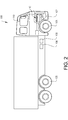
- the vehicle 100 may for example be a truck, as illustrated in fig. 2 , or some other heavy-duty vehicle, such as a bus or construction equipment.
- the fuel system 10 comprises an accumulator in the form of a common rail 12, and a plurality of injectors 14a-f, here six injectors. Each injector 14a-f is in fluid communication with the common rail 12. Each injector 14a-f may perform an injection of fuel coming from the common rail 12 into a respective combustion chamber 104a-f of the combustion engine 102.
- the fuel system 10 may further comprise a tank 18, for example a liquefied natural gas (LNG) tank, a pump 20 connected to the tank 18, and an evaporator 22 connected to the pump 20.
- the pump 20 may pump liquefied natural gas from the tank 18 to the evaporator 22 where the liquefied natural gas is evaporated to form gaseous fuel, i.e. natural gas in this case.
- An inlet valve 24 of the fuel system 10 is arranged between the evaporator 22 and the common rail 12 and adapted to regulate input of gaseous fuel from the evaporator 22 to the common rail 12.
- a buffer (not shown) could be provided between the evaporator 22 and the inlet valve 24.
- the fuel system 10 may further comprise a release valve 26 adapted to regulate venting of gaseous fuel from the common rail 12 to another tank 28 of the fuel system 10.
- the fuel system 10 further comprises nominal fuel amount determination means 30 configured to determine a nominal amount of gaseous fuel to be introduced into the common rail 12.
- the nominal fuel amount determination means 30 may be a fuel injection control function, as the nominal amount of gaseous fuel to be introduced into the common rail 12 should be equal to the fuel demand of the combustion engine 102, which fuel demand in turn depends on torque demand.
- the fuel amount/demand may be expressed as gaseous fuel mass flow rate (kg/s).
- the fuel system 10 further comprises a control unit 32, namely an electronic control unit, connected to the inlet valve 24 and the release valve 26.
- the inlet valve 24 and the release valve 26 are preferably individually and electrically operated, and controlled by the control unit 32.
- the control unit 32 is also configured to trigger injections by the injectors 14a-f.
- the control unit 32 may be connected to the nominal fuel amount determination means 30 and receive the determined nominal amount of gaseous fuel to be introduced into the common rail 12 from the nominal fuel amount determination means 30.
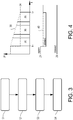
- a method according to an embodiment of the invention including normal operation (not shutting down of engine 102) will in the following be described with further reference to figs. 3-4 .
- pressure P is on the vertical axis and time t is on the horizontal axis.
- positions of the inlet valve 24 and the release valve 26 are illustrated in fig. 4 .
- step S1 a nominal amount of gaseous fuel to be introduced into the common rail 12 is determined by the nominal fuel amount determination means 30 at time t1. At time t1, the current pressure need 34 (dashed line) of the common rail 12 is decreased.
- step S2 less gaseous fuel than the determined nominal amount is introduced into the common rail 12 by closing the inlet valve 24, as controlled by the control unit 32.
- injections 36 of gaseous fuel into the combustion chambers 104a-f are performed by the injectors 14a-f in step S3, as triggered by the control unit 32, such that the gaseous fuel pressure 38 in the common rail 12 is reduced, preferably without venting gaseous fuel from the common rail 12 to the tank 28 via the release valve 26.
- the release valve is closed during step S3. The gaseous fuel in the injections 36 comes from the common rail 12.
- each injection 36 in step S3 contribute to combustion in the combustion engine 102. That is, the injections 36 contribute to torque generation. Furthermore, each injection 36 preferable has a duration which is longer than but near the minimum duration, wherein minimum duration is the shortest time that the injectors 14a-f can be open. The near minimum duration of the injections 36 may for example be up to 120% of the minimum duration. If the injections 36 are shorter, it may take too long time to reduce the pressure, and if the injections 36 are longer they may generate too much excessive torque.
- less gaseous fuel may be introduced by merely reducing the inlet valve 24 more than the current pressure need stipulates, as controlled by the control unit 32 taking into account the nominal fuel amount from the nominal fuel amount determination means 30.
- the "normal" position of the inlet valve 24 as stipulated by the current pressure need is indicated by 40.
- the gaseous fuel mass flow rate at the inlet valve 24 should be lower than the gaseous fuel mass flow rate of the injections 36, such that less fuel comes in than what comes out, whereby the pressure in the common rail 12 may be reduced without venting.
- Excessive torque caused by the injections 36 used to reduce the pressure in the common rail 12 may be mitigated in step S4.
- the excessive torque may for example be mitigated by braking the vehicle 100 using brakes 105.
- the excessive torque may be mitigated by recuperating the energy of the excessive torque in an electric machine 106 and/or energy storage 108 of the vehicle 100, in which case energy losses may be reduced or minimized.
- the inlet valve 24 may be set to its "normal" position as stipulated by the current pressure need.
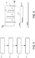
- a method according to another embodiment of the invention will in the following be described with further reference to figs. 5-6 .
- the method in figs. 5-6 is similar to that of figs. 3-4 , but in figs. 5-6 the pressure is reduced in advance in response to a predicted future pressure need of the common rail 12, rather than in response to the current pressure need.
- a future pressure need of the common rail 12 at time t2 namely a decrease in pressure need 34
- the future accumulator pressure need may for example be predicted by means of an e-horizon system 110 (see fig. 2 ), such as Volvo Trucks' I-See system.
- the e-horizon system 110 may for example predict a future decrease in pressure need based on an upcoming speed limit reduction along the road that the vehicle 100 is travelling.
- step S1' a nominal amount of gaseous fuel to be introduced into the common rail 12 is determined by the nominal fuel amount determination means 30 at time t1, wherein the (current) pressure need 34 of the common rail 12 at time t1 is higher than the predicted future pressure need at time t2.
- step S2' less gaseous fuel than the determined nominal amount is introduced into the common rail 12 by reducing the inlet valve 24 compared to the stipulated position 40, as controlled by the control unit 32.
- injections 36 of gaseous fuel into the combustion chambers 104a-f are performed by the injectors 14a-f in step S3', as triggered by the control unit 32, such that the gaseous fuel pressure 38 in the common rail 12 is reduced before time t2, preferably without venting gaseous fuel from the common rail 12 to the tank 28 via the release valve 26.
- the release valve is closed during step S3'.
- the gaseous fuel in the injections 36 comes from the common rail 12.
- the gaseous fuel mass flow rate at the inlet valve 24 should here be lower than the gaseous fuel mass flow rate of the injections 36, such that less fuel comes in than what comes out, whereby the pressure in the common rail 12 may be reduced in advance without venting.
- each injection 36 in step S3' contribute to combustion in the combustion engine 102. That is, the injections 36 contribute to torque generation. Furthermore, each injection 36 may here have a prolonged duration compared to a nominal duration for the current pressure need 34, to compensate for the in advance reduction of gaseous fuel pressure 38 in the common rail 12. Each injection 36 in fig. 6 may for example be prolonged by up to 50% compared to the nominal duration.
- the inlet valve 24 may be set to its "normal” position as stipulated by the current pressure need.
- Fig. 7 illustrates the fuel system 10 similar to that of fig. 1 , but without the tank 18, the pump 20, the evaporator 22, the release valve 26, and the other tank 28.
- the inlet and release valves 24, 26 may be mechanically coupled and synchronized, wherein both may be closed at the same time by operating the valves 24, 26 in a deadband (offset).
- the inlet valve 24 for methane may be reduced or closed by controlling the diesel pressure accordingly.
- each injector may have an accumulator in the form of a high pressure chamber, which injectors may be referred to as unit injectors.
Landscapes
- Engineering & Computer Science (AREA)
- Chemical & Material Sciences (AREA)
- Combustion & Propulsion (AREA)
- Mechanical Engineering (AREA)
- General Engineering & Computer Science (AREA)
- Oil, Petroleum & Natural Gas (AREA)
- Chemical Kinetics & Catalysis (AREA)
- General Chemical & Material Sciences (AREA)
- Electrical Control Of Air Or Fuel Supplied To Internal-Combustion Engine (AREA)
- Fuel-Injection Apparatus (AREA)
- Output Control And Ontrol Of Special Type Engine (AREA)
Claims (15)
- Verfahren zur Steuerung von Gaskraftstoffdruck in einem Akkumulator (12) eines Kraftstoffsystems (10) für einen Verbrennungsmotor (102) eines Fahrzeugs (100) mit den Schritten:Bestimmen einer nominalen Menge an Gaskraftstoff, die in den Akkumulator eingeführt werden soll; wobei die nominale Menge von der Drehmomentanforderung abhängt,
Einführen von weniger Gaskraftstoff in den Akkumulator als die bestimmte nominale Menge, als Reaktion auf eine abnehmende Kraftstoffanforderung durch Reduzieren oder Schließen eines Einlassventils (24), wobei das Einlassventil angepasst ist, die Zufuhr von Gaskraftstoff in den Akkumulator zu regulieren;während das Einlassventil reduziert oder geschlossen wird, Durchführen mindestens einer Einspritzung von aus dem Akkumulator kommenden Gaskraftstoff in mindestens eine Brennkammer (104a-f) des Verbrennungsmotors durch mindestens einen Einspritzer (14a-f) des Kraftstoffsystems, wobei die mindestens eine Einspritzung zur Verbrennung im Verbrennungsmotor beiträgt, wodurch der Druck im Akkumulator reduziert wird, undAbmildern eines eventuellen, durch das Reduzieren des Drucks durch Bremsen des Fahrzeugs verursachten, übermäßigen Drehmoments, oderAbmildern eines eventuellen, durch das Reduzieren des Drucks durch Rückgewinnen der Energie des übermäßigen Drehmoments in einer elektrischen Maschine und/oder einem Energiespeicher des Fahrzeugs verursachten, übermäßigen Drehmoments. - Verfahren nach Anspruch 1, wobei die mindestens eine Einspritzung durchgeführt wird, ohne Gaskraftstoff aus dem Akkumulator zu einem Tank (28) des Kraftstoffsystems zu entlüften.
- Verfahren nach Anspruch 1 oder 2, wobei das Kraftstoffsystem ferner ein Freigabeventil (26) umfasst, das angepasst ist, die Entlüftung von Gaskraftstoff aus dem Akkumulator zu einem Tank (28) des Kraftstoffsystems zu regulieren, und wobei die mindestens eine Einspritzung durchgeführt wird, während das Freigabeventil geschlossen ist.
- Verfahren nach Anspruch 3, wobei das Einlassventil und das Freigabeventil einzeln und elektrisch betrieben werden.
- Verfahren nach einem der vorhergehenden Ansprüche, wobei das Reduzieren des Drucks als Reaktion auf einen aktuellen Akkumulatordruckbedarf durchgeführt wird.
- Verfahren nach einem der vorhergehenden Ansprüche, wobei die mindestens eine Einspritzung eine nahezu minimale Dauer aufweist.
- Verfahren nach einem der vorhergehenden Ansprüche, ferner umfassend:Vorhersagen eines zukünftigen Akkumulatordruckbedarfs,wobei das Reduzieren des Drucks im Voraus, als Reaktion auf den vorhergesagte zukünftigen Akkumulatordruckbedarf durchgeführt wird.
- Verfahren nach Anspruch 7, ferner umfassend:Abmildern des Reduzierens des Drucks im Voraus, durch Verlängerung der Dauer der mindestens einen Einspritzung.
- Verfahren nach einem der vorhergehenden Ansprüche, wobei das Einlassventil reduziert oder geschlossen wird und die mindestens eine Einspritzung derart durchgeführt wird, dass das Einlassventil einen reduzierten Gaskraftstoffmassenstrom im Vergleich zu dem Gaskraftstoffmassenstrom der mindestens einen Einspritzung aufweist.
- Verfahren nach einem der vorhergehenden Ansprüche, wobei der Akkumulator ein Comon-Rail (12) in Fluidverbindung mit dem mindestens einen Einspritzer ist.
- Verfahren nach einem der vorstehenden Ansprüche, wobei der Gaskraftstoff Erdgas oder Biogas ist.
- Kraftstoffsystem (10) für einen Verbrennungsmotor (102) eines Fahrzeugs (100), wobei das Kraftstoffsystem umfasst:einen Akkumulator (12);ein Einlassventil (24), das angepasst ist, die Zufuhr von Gaskraftstoff zum Akkumulator zu regulieren;mindestens einen Einspritzer (14a-f);Mittel (30), die konfiguriert sind zum Bestimmen einer nominalen Menge an Gaskraftstoff, die in den Akkumulator eingeführt werden soll; wobei die nominale Menge von der Drehmomentanforderung abhängt, undeine Steuereinheit (32), die konfiguriert ist, um das Einlassventil zu reduzieren oder zu schließen, um so, als Reaktion auf eine abnehmende Kraftstoffanforderung weniger Gaskraftstoff in den Akkumulator einzuführen, als die durch das Mittel bestimmte nominale Menge, und um mindestens eine Einspritzung von aus dem Akkumulator kommendem Gaskraftstoff in mindestens eine Brennkammer des Verbrennungsmotors durch den mindestens einen Einspritzer auszulösen, während das Einlassventil reduziert oder geschlossen wird, wobei die mindestens eine Einspritzung zur Verbrennung im Verbrennungsmotor beiträgt, wodurch der Druck im Akkumulator reduziert wird, und konfiguriert, um ein eventuelles, durch das Reduzieren des Drucks durch Bremsen des Fahrzeugs verursachtes, übermäßiges Drehmoment abzumildern, oder um ein eventuelles, durch das Reduzieren des Drucks durch Rückgewinnen der Energie des übermäßigen Drehmoments in einer elektrischen Maschine und/oder einem Energiespeicher des Fahrzeugs verursachtes, übermäßiges Drehmoment abzumildern.
- Computerprogramm, das Programmcodemittel zum Durchführen der Schritte nach einem der Ansprüche 1-11 umfasst, wenn das Programm auf einem Computer läuft.
- Steuereinheit (22) zur Steuerung eines Gaskraftstoffdrucks in einem Ackumulator eines Kraftstoffsystems für einen Verbrennungsmotor eines Fahrzeugs, wobei die Steuereinheit konfiguriert ist, um die Schritte des Verfahrens nach einem der Ansprüche 1 bis 11 durchzuführen oder auszulösen.
- Fahrzeug (100), umfassend ein Kraftstoffsystem (10) nach Anspruch 12.
Applications Claiming Priority (1)
| Application Number | Priority Date | Filing Date | Title |
|---|---|---|---|
| PCT/EP2017/080260 WO2019101326A1 (en) | 2017-11-23 | 2017-11-23 | A method for controlling gaseous fuel pressure |
Publications (2)
| Publication Number | Publication Date |
|---|---|
| EP3714152A1 EP3714152A1 (de) | 2020-09-30 |
| EP3714152B1 true EP3714152B1 (de) | 2021-07-28 |
Family
ID=60935761
Family Applications (1)
| Application Number | Title | Priority Date | Filing Date |
|---|---|---|---|
| EP17825371.2A Active EP3714152B1 (de) | 2017-11-23 | 2017-11-23 | Verfahren zur steuerung des drucks von gasförmigem kraftstoff |
Country Status (4)
| Country | Link |
|---|---|
| US (2) | US11268461B2 (de) |
| EP (1) | EP3714152B1 (de) |
| CN (1) | CN111417774B (de) |
| WO (1) | WO2019101326A1 (de) |
Cited By (1)
| Publication number | Priority date | Publication date | Assignee | Title |
|---|---|---|---|---|
| GB2636594A (en) * | 2023-12-18 | 2025-06-25 | Phinia Delphi Luxembourg Sarl | Method for controlling a fuel-supply system for a gaseous-fuel engine |
Families Citing this family (1)
| Publication number | Priority date | Publication date | Assignee | Title |
|---|---|---|---|---|
| US12467414B2 (en) * | 2021-06-23 | 2025-11-11 | Cespira Canada Limited Partnership | Apparatus and method for pressurizing and supplying gaseous fuel to an internal combustion engine |
Family Cites Families (14)
| Publication number | Priority date | Publication date | Assignee | Title |
|---|---|---|---|---|
| US4459084A (en) * | 1981-05-26 | 1984-07-10 | Clark Garry E | Internal combustion driven pumping system and variable torque transmission |
| US4606708A (en) * | 1981-05-26 | 1986-08-19 | Clark Garry E | Internal combustion driven pumping system and variable torque transmission |
| US4541243A (en) * | 1981-05-26 | 1985-09-17 | Clark Garry E | Internal combustion driven pumping system and variable torque transmission |
| JP2003120457A (ja) | 2001-09-18 | 2003-04-23 | Hyundai Motor Co Ltd | 燃料噴射圧力制御システム及びその方法 |
| JP3931120B2 (ja) | 2002-07-10 | 2007-06-13 | ボッシュ株式会社 | 蓄圧式燃料噴射装置 |
| JP2005256703A (ja) | 2004-03-11 | 2005-09-22 | Denso Corp | 蓄圧式燃料噴射装置 |
| JP2006291843A (ja) | 2005-04-11 | 2006-10-26 | Denso Corp | 燃料噴射装置 |
| JP4506662B2 (ja) * | 2005-12-05 | 2010-07-21 | 株式会社デンソー | 燃料噴射制御装置 |
| DE102008006567A1 (de) * | 2008-01-29 | 2009-07-30 | Robert Bosch Gmbh | Verfahren und Vorrichtung zum Einstellen eines Betriebsdruckes in einem Kraftstoffreservoir |
| EP2123890A1 (de) * | 2008-05-21 | 2009-11-25 | GM Global Technology Operations, Inc. | Verfahren und Vorrichtung zur Steuerung des Betriebdrucks eines Common-Rail-Einspritzsystems |
| US8346418B2 (en) * | 2009-11-30 | 2013-01-01 | GM Global Technology Operations LLC | Method of smoothing output torque |
| US8439016B2 (en) * | 2009-12-15 | 2013-05-14 | GM Global Technology Operations LLC | Liquefied petroleum gas engine assembly with flow control |
| DE102015225279B4 (de) * | 2015-12-15 | 2019-09-12 | Mtu Friedrichshafen Gmbh | Verfahren und Einrichtung zum prädiktiven Steuern und/oder Regeln einer Brennkraftmaschine sowie Brennkraftmaschine mit der Einrichtung zur Ausführung des Verfahrens |
| JP7226173B2 (ja) * | 2019-07-30 | 2023-02-21 | 株式会社デンソー | 燃料噴射システムの制御装置 |
-
2017
- 2017-11-23 EP EP17825371.2A patent/EP3714152B1/de active Active
- 2017-11-23 US US16/766,420 patent/US11268461B2/en active Active
- 2017-11-23 CN CN201780097097.4A patent/CN111417774B/zh active Active
- 2017-11-23 WO PCT/EP2017/080260 patent/WO2019101326A1/en not_active Ceased
-
2022
- 2022-02-03 US US17/649,872 patent/US11560858B2/en active Active
Cited By (1)
| Publication number | Priority date | Publication date | Assignee | Title |
|---|---|---|---|---|
| GB2636594A (en) * | 2023-12-18 | 2025-06-25 | Phinia Delphi Luxembourg Sarl | Method for controlling a fuel-supply system for a gaseous-fuel engine |
Also Published As
| Publication number | Publication date |
|---|---|
| US11560858B2 (en) | 2023-01-24 |
| US20220154656A1 (en) | 2022-05-19 |
| EP3714152A1 (de) | 2020-09-30 |
| CN111417774B (zh) | 2022-05-06 |
| WO2019101326A1 (en) | 2019-05-31 |
| US11268461B2 (en) | 2022-03-08 |
| US20210062737A1 (en) | 2021-03-04 |
| CN111417774A (zh) | 2020-07-14 |
Similar Documents
| Publication | Publication Date | Title |
|---|---|---|
| US20220154656A1 (en) | Method for controlling gaseous fuel pressure | |
| US9534544B2 (en) | Electric hybrid powertrain regeneration efficiency improvement | |
| US8515652B2 (en) | Control device for internal combustion engine | |
| US8977473B2 (en) | Pressure control strategy for dual fuel compression ignition engine and machine using same | |
| US20120010047A1 (en) | Method and device for controlling the clutch in coasting operation of a motor vehicle | |
| KR20100058594A (ko) | 차량 구동 유닛의 제어 장치 | |
| US20130333969A1 (en) | Method for Controlling Pressure in a Vehicle and Pressure Control Device | |
| KR20130029879A (ko) | 하이브리드 차량의 페일 세이프티 제어 방법 | |
| EP2543855B1 (de) | Fahrzeug mit einem verbrennungsmotor mit einem ventilstoppmechanismus | |
| US9168902B2 (en) | Method and system for controlling braking of vehicle | |
| US20260049694A1 (en) | Hydrogen (h2) fuel tank system control for improved h2 vehicle efficiency and range | |
| US8074527B2 (en) | Monitoring system for a hybrid drive | |
| CN115328221A (zh) | 一种供气控制方法、装置、设备及存储介质 | |
| US20110083649A1 (en) | Control device for internal combustion engine | |
| JP2002285905A (ja) | 車両制御システム | |
| JP4937837B2 (ja) | 内燃機関制御装置 | |
| US11649773B2 (en) | Control device and method for controlling a compression release brake arrangement for an engine | |
| US20210159525A1 (en) | Fuel cell system | |
| US20190309691A1 (en) | Apparatus and method for controlling variable compression ratio engine | |
| CN106103949B (zh) | 具有汽缸钝化的机动车辆的内燃发动机 | |
| EP4118362B1 (de) | Verfahren zur steuerung eines antriebsstrangs | |
| KR20240176675A (ko) | 친환경 차량의 ams 제어 방법 | |
| JP4755608B2 (ja) | 燃料噴射制御装置 | |
| CN106988909A (zh) | 减少内燃机运行中的爆震事件 | |
| JP2008144702A (ja) | 燃料噴射制御装置 |
Legal Events
| Date | Code | Title | Description |
|---|---|---|---|
| STAA | Information on the status of an ep patent application or granted ep patent |
Free format text: STATUS: UNKNOWN |
|
| STAA | Information on the status of an ep patent application or granted ep patent |
Free format text: STATUS: THE INTERNATIONAL PUBLICATION HAS BEEN MADE |
|
| PUAI | Public reference made under article 153(3) epc to a published international application that has entered the european phase |
Free format text: ORIGINAL CODE: 0009012 |
|
| STAA | Information on the status of an ep patent application or granted ep patent |
Free format text: STATUS: REQUEST FOR EXAMINATION WAS MADE |
|
| 17P | Request for examination filed |
Effective date: 20200623 |
|
| AK | Designated contracting states |
Kind code of ref document: A1 Designated state(s): AL AT BE BG CH CY CZ DE DK EE ES FI FR GB GR HR HU IE IS IT LI LT LU LV MC MK MT NL NO PL PT RO RS SE SI SK SM TR |
|
| AX | Request for extension of the european patent |
Extension state: BA ME |
|
| DAV | Request for validation of the european patent (deleted) | ||
| DAX | Request for extension of the european patent (deleted) | ||
| GRAP | Despatch of communication of intention to grant a patent |
Free format text: ORIGINAL CODE: EPIDOSNIGR1 |
|
| STAA | Information on the status of an ep patent application or granted ep patent |
Free format text: STATUS: GRANT OF PATENT IS INTENDED |
|
| INTG | Intention to grant announced |
Effective date: 20210409 |
|
| GRAS | Grant fee paid |
Free format text: ORIGINAL CODE: EPIDOSNIGR3 |
|
| GRAA | (expected) grant |
Free format text: ORIGINAL CODE: 0009210 |
|
| STAA | Information on the status of an ep patent application or granted ep patent |
Free format text: STATUS: THE PATENT HAS BEEN GRANTED |
|
| AK | Designated contracting states |
Kind code of ref document: B1 Designated state(s): AL AT BE BG CH CY CZ DE DK EE ES FI FR GB GR HR HU IE IS IT LI LT LU LV MC MK MT NL NO PL PT RO RS SE SI SK SM TR |
|
| REG | Reference to a national code |
Ref country code: GB Ref legal event code: FG4D |
|
| REG | Reference to a national code |
Ref country code: CH Ref legal event code: EP |
|
| REG | Reference to a national code |
Ref country code: AT Ref legal event code: REF Ref document number: 1414935 Country of ref document: AT Kind code of ref document: T Effective date: 20210815 |
|
| REG | Reference to a national code |
Ref country code: IE Ref legal event code: FG4D |
|
| REG | Reference to a national code |
Ref country code: DE Ref legal event code: R096 Ref document number: 602017043057 Country of ref document: DE |
|
| REG | Reference to a national code |
Ref country code: LT Ref legal event code: MG9D |
|
| REG | Reference to a national code |
Ref country code: NL Ref legal event code: MP Effective date: 20210728 |
|
| REG | Reference to a national code |
Ref country code: AT Ref legal event code: MK05 Ref document number: 1414935 Country of ref document: AT Kind code of ref document: T Effective date: 20210728 |
|
| PG25 | Lapsed in a contracting state [announced via postgrant information from national office to epo] |
Ref country code: LT Free format text: LAPSE BECAUSE OF FAILURE TO SUBMIT A TRANSLATION OF THE DESCRIPTION OR TO PAY THE FEE WITHIN THE PRESCRIBED TIME-LIMIT Effective date: 20210728 Ref country code: AT Free format text: LAPSE BECAUSE OF FAILURE TO SUBMIT A TRANSLATION OF THE DESCRIPTION OR TO PAY THE FEE WITHIN THE PRESCRIBED TIME-LIMIT Effective date: 20210728 Ref country code: BG Free format text: LAPSE BECAUSE OF FAILURE TO SUBMIT A TRANSLATION OF THE DESCRIPTION OR TO PAY THE FEE WITHIN THE PRESCRIBED TIME-LIMIT Effective date: 20211028 Ref country code: NL Free format text: LAPSE BECAUSE OF FAILURE TO SUBMIT A TRANSLATION OF THE DESCRIPTION OR TO PAY THE FEE WITHIN THE PRESCRIBED TIME-LIMIT Effective date: 20210728 Ref country code: PT Free format text: LAPSE BECAUSE OF FAILURE TO SUBMIT A TRANSLATION OF THE DESCRIPTION OR TO PAY THE FEE WITHIN THE PRESCRIBED TIME-LIMIT Effective date: 20211129 Ref country code: NO Free format text: LAPSE BECAUSE OF FAILURE TO SUBMIT A TRANSLATION OF THE DESCRIPTION OR TO PAY THE FEE WITHIN THE PRESCRIBED TIME-LIMIT Effective date: 20211028 Ref country code: SE Free format text: LAPSE BECAUSE OF FAILURE TO SUBMIT A TRANSLATION OF THE DESCRIPTION OR TO PAY THE FEE WITHIN THE PRESCRIBED TIME-LIMIT Effective date: 20210728 Ref country code: RS Free format text: LAPSE BECAUSE OF FAILURE TO SUBMIT A TRANSLATION OF THE DESCRIPTION OR TO PAY THE FEE WITHIN THE PRESCRIBED TIME-LIMIT Effective date: 20210728 Ref country code: HR Free format text: LAPSE BECAUSE OF FAILURE TO SUBMIT A TRANSLATION OF THE DESCRIPTION OR TO PAY THE FEE WITHIN THE PRESCRIBED TIME-LIMIT Effective date: 20210728 Ref country code: FI Free format text: LAPSE BECAUSE OF FAILURE TO SUBMIT A TRANSLATION OF THE DESCRIPTION OR TO PAY THE FEE WITHIN THE PRESCRIBED TIME-LIMIT Effective date: 20210728 Ref country code: ES Free format text: LAPSE BECAUSE OF FAILURE TO SUBMIT A TRANSLATION OF THE DESCRIPTION OR TO PAY THE FEE WITHIN THE PRESCRIBED TIME-LIMIT Effective date: 20210728 |
|
| PG25 | Lapsed in a contracting state [announced via postgrant information from national office to epo] |
Ref country code: PL Free format text: LAPSE BECAUSE OF FAILURE TO SUBMIT A TRANSLATION OF THE DESCRIPTION OR TO PAY THE FEE WITHIN THE PRESCRIBED TIME-LIMIT Effective date: 20210728 Ref country code: LV Free format text: LAPSE BECAUSE OF FAILURE TO SUBMIT A TRANSLATION OF THE DESCRIPTION OR TO PAY THE FEE WITHIN THE PRESCRIBED TIME-LIMIT Effective date: 20210728 Ref country code: GR Free format text: LAPSE BECAUSE OF FAILURE TO SUBMIT A TRANSLATION OF THE DESCRIPTION OR TO PAY THE FEE WITHIN THE PRESCRIBED TIME-LIMIT Effective date: 20211029 |
|
| PG25 | Lapsed in a contracting state [announced via postgrant information from national office to epo] |
Ref country code: DK Free format text: LAPSE BECAUSE OF FAILURE TO SUBMIT A TRANSLATION OF THE DESCRIPTION OR TO PAY THE FEE WITHIN THE PRESCRIBED TIME-LIMIT Effective date: 20210728 |
|
| REG | Reference to a national code |
Ref country code: DE Ref legal event code: R097 Ref document number: 602017043057 Country of ref document: DE |
|
| PG25 | Lapsed in a contracting state [announced via postgrant information from national office to epo] |
Ref country code: SM Free format text: LAPSE BECAUSE OF FAILURE TO SUBMIT A TRANSLATION OF THE DESCRIPTION OR TO PAY THE FEE WITHIN THE PRESCRIBED TIME-LIMIT Effective date: 20210728 Ref country code: SK Free format text: LAPSE BECAUSE OF FAILURE TO SUBMIT A TRANSLATION OF THE DESCRIPTION OR TO PAY THE FEE WITHIN THE PRESCRIBED TIME-LIMIT Effective date: 20210728 Ref country code: RO Free format text: LAPSE BECAUSE OF FAILURE TO SUBMIT A TRANSLATION OF THE DESCRIPTION OR TO PAY THE FEE WITHIN THE PRESCRIBED TIME-LIMIT Effective date: 20210728 Ref country code: EE Free format text: LAPSE BECAUSE OF FAILURE TO SUBMIT A TRANSLATION OF THE DESCRIPTION OR TO PAY THE FEE WITHIN THE PRESCRIBED TIME-LIMIT Effective date: 20210728 Ref country code: CZ Free format text: LAPSE BECAUSE OF FAILURE TO SUBMIT A TRANSLATION OF THE DESCRIPTION OR TO PAY THE FEE WITHIN THE PRESCRIBED TIME-LIMIT Effective date: 20210728 Ref country code: AL Free format text: LAPSE BECAUSE OF FAILURE TO SUBMIT A TRANSLATION OF THE DESCRIPTION OR TO PAY THE FEE WITHIN THE PRESCRIBED TIME-LIMIT Effective date: 20210728 |
|
| PLBE | No opposition filed within time limit |
Free format text: ORIGINAL CODE: 0009261 |
|
| STAA | Information on the status of an ep patent application or granted ep patent |
Free format text: STATUS: NO OPPOSITION FILED WITHIN TIME LIMIT |
|
| PG25 | Lapsed in a contracting state [announced via postgrant information from national office to epo] |
Ref country code: MC Free format text: LAPSE BECAUSE OF FAILURE TO SUBMIT A TRANSLATION OF THE DESCRIPTION OR TO PAY THE FEE WITHIN THE PRESCRIBED TIME-LIMIT Effective date: 20210728 |
|
| REG | Reference to a national code |
Ref country code: CH Ref legal event code: PL |
|
| 26N | No opposition filed |
Effective date: 20220429 |
|
| GBPC | Gb: european patent ceased through non-payment of renewal fee |
Effective date: 20211123 |
|
| PG25 | Lapsed in a contracting state [announced via postgrant information from national office to epo] |
Ref country code: LU Free format text: LAPSE BECAUSE OF NON-PAYMENT OF DUE FEES Effective date: 20211123 Ref country code: IT Free format text: LAPSE BECAUSE OF FAILURE TO SUBMIT A TRANSLATION OF THE DESCRIPTION OR TO PAY THE FEE WITHIN THE PRESCRIBED TIME-LIMIT Effective date: 20210728 Ref country code: BE Free format text: LAPSE BECAUSE OF NON-PAYMENT OF DUE FEES Effective date: 20211130 |
|
| REG | Reference to a national code |
Ref country code: BE Ref legal event code: MM Effective date: 20211130 |
|
| PG25 | Lapsed in a contracting state [announced via postgrant information from national office to epo] |
Ref country code: IE Free format text: LAPSE BECAUSE OF NON-PAYMENT OF DUE FEES Effective date: 20211123 Ref country code: GB Free format text: LAPSE BECAUSE OF NON-PAYMENT OF DUE FEES Effective date: 20211123 |
|
| PG25 | Lapsed in a contracting state [announced via postgrant information from national office to epo] |
Ref country code: CY Free format text: LAPSE BECAUSE OF FAILURE TO SUBMIT A TRANSLATION OF THE DESCRIPTION OR TO PAY THE FEE WITHIN THE PRESCRIBED TIME-LIMIT Effective date: 20210728 |
|
| PG25 | Lapsed in a contracting state [announced via postgrant information from national office to epo] |
Ref country code: LI Free format text: LAPSE BECAUSE OF NON-PAYMENT OF DUE FEES Effective date: 20220630 Ref country code: HU Free format text: LAPSE BECAUSE OF FAILURE TO SUBMIT A TRANSLATION OF THE DESCRIPTION OR TO PAY THE FEE WITHIN THE PRESCRIBED TIME-LIMIT; INVALID AB INITIO Effective date: 20171123 Ref country code: CH Free format text: LAPSE BECAUSE OF NON-PAYMENT OF DUE FEES Effective date: 20220630 |
|
| PG25 | Lapsed in a contracting state [announced via postgrant information from national office to epo] |
Ref country code: MK Free format text: LAPSE BECAUSE OF FAILURE TO SUBMIT A TRANSLATION OF THE DESCRIPTION OR TO PAY THE FEE WITHIN THE PRESCRIBED TIME-LIMIT Effective date: 20210728 |
|
| PG25 | Lapsed in a contracting state [announced via postgrant information from national office to epo] |
Ref country code: TR Free format text: LAPSE BECAUSE OF FAILURE TO SUBMIT A TRANSLATION OF THE DESCRIPTION OR TO PAY THE FEE WITHIN THE PRESCRIBED TIME-LIMIT Effective date: 20210728 |
|
| PG25 | Lapsed in a contracting state [announced via postgrant information from national office to epo] |
Ref country code: MT Free format text: LAPSE BECAUSE OF FAILURE TO SUBMIT A TRANSLATION OF THE DESCRIPTION OR TO PAY THE FEE WITHIN THE PRESCRIBED TIME-LIMIT Effective date: 20210728 |
|
| PGFP | Annual fee paid to national office [announced via postgrant information from national office to epo] |
Ref country code: FR Payment date: 20241126 Year of fee payment: 8 |
|
| PGFP | Annual fee paid to national office [announced via postgrant information from national office to epo] |
Ref country code: DE Payment date: 20251126 Year of fee payment: 9 |