EP3713824B1 - Combined braking system for vehicles, especially for motorcycles - Google Patents
Combined braking system for vehicles, especially for motorcycles Download PDFInfo
- Publication number
- EP3713824B1 EP3713824B1 EP18811663.6A EP18811663A EP3713824B1 EP 3713824 B1 EP3713824 B1 EP 3713824B1 EP 18811663 A EP18811663 A EP 18811663A EP 3713824 B1 EP3713824 B1 EP 3713824B1
- Authority
- EP
- European Patent Office
- Prior art keywords
- rotating element
- braking system
- actuating
- actuating cable
- combined
- Prior art date
- Legal status (The legal status is an assumption and is not a legal conclusion. Google has not performed a legal analysis and makes no representation as to the accuracy of the status listed.)
- Active
Links
- 230000009471 action Effects 0.000 claims description 15
- 230000007246 mechanism Effects 0.000 claims description 12
- 238000006243 chemical reaction Methods 0.000 claims description 11
- 238000006073 displacement reaction Methods 0.000 claims description 2
- 230000000284 resting effect Effects 0.000 claims description 2
- 230000004913 activation Effects 0.000 description 3
- 229910000831 Steel Inorganic materials 0.000 description 2
- 230000008878 coupling Effects 0.000 description 2
- 238000010168 coupling process Methods 0.000 description 2
- 238000005859 coupling reaction Methods 0.000 description 2
- 239000010959 steel Substances 0.000 description 2
- 239000004809 Teflon Substances 0.000 description 1
- 229920006362 Teflon® Polymers 0.000 description 1
- 230000006978 adaptation Effects 0.000 description 1
- 239000003831 antifriction material Substances 0.000 description 1
- 230000005540 biological transmission Effects 0.000 description 1
- 230000004048 modification Effects 0.000 description 1
- 238000012986 modification Methods 0.000 description 1
- 230000036316 preload Effects 0.000 description 1
- 238000004513 sizing Methods 0.000 description 1
Images


Classifications
-
- B—PERFORMING OPERATIONS; TRANSPORTING
- B60—VEHICLES IN GENERAL
- B60T—VEHICLE BRAKE CONTROL SYSTEMS OR PARTS THEREOF; BRAKE CONTROL SYSTEMS OR PARTS THEREOF, IN GENERAL; ARRANGEMENT OF BRAKING ELEMENTS ON VEHICLES IN GENERAL; PORTABLE DEVICES FOR PREVENTING UNWANTED MOVEMENT OF VEHICLES; VEHICLE MODIFICATIONS TO FACILITATE COOLING OF BRAKES
- B60T11/00—Transmitting braking action from initiating means to ultimate brake actuator without power assistance or drive or where such assistance or drive is irrelevant
- B60T11/04—Transmitting braking action from initiating means to ultimate brake actuator without power assistance or drive or where such assistance or drive is irrelevant transmitting mechanically
- B60T11/046—Using cables
-
- B—PERFORMING OPERATIONS; TRANSPORTING
- B60—VEHICLES IN GENERAL
- B60T—VEHICLE BRAKE CONTROL SYSTEMS OR PARTS THEREOF; BRAKE CONTROL SYSTEMS OR PARTS THEREOF, IN GENERAL; ARRANGEMENT OF BRAKING ELEMENTS ON VEHICLES IN GENERAL; PORTABLE DEVICES FOR PREVENTING UNWANTED MOVEMENT OF VEHICLES; VEHICLE MODIFICATIONS TO FACILITATE COOLING OF BRAKES
- B60T11/00—Transmitting braking action from initiating means to ultimate brake actuator without power assistance or drive or where such assistance or drive is irrelevant
- B60T11/04—Transmitting braking action from initiating means to ultimate brake actuator without power assistance or drive or where such assistance or drive is irrelevant transmitting mechanically
- B60T11/06—Equalising arrangements
-
- B—PERFORMING OPERATIONS; TRANSPORTING
- B60—VEHICLES IN GENERAL
- B60T—VEHICLE BRAKE CONTROL SYSTEMS OR PARTS THEREOF; BRAKE CONTROL SYSTEMS OR PARTS THEREOF, IN GENERAL; ARRANGEMENT OF BRAKING ELEMENTS ON VEHICLES IN GENERAL; PORTABLE DEVICES FOR PREVENTING UNWANTED MOVEMENT OF VEHICLES; VEHICLE MODIFICATIONS TO FACILITATE COOLING OF BRAKES
- B60T8/00—Arrangements for adjusting wheel-braking force to meet varying vehicular or ground-surface conditions, e.g. limiting or varying distribution of braking force
- B60T8/26—Arrangements for adjusting wheel-braking force to meet varying vehicular or ground-surface conditions, e.g. limiting or varying distribution of braking force characterised by producing differential braking between front and rear wheels
- B60T8/261—Arrangements for adjusting wheel-braking force to meet varying vehicular or ground-surface conditions, e.g. limiting or varying distribution of braking force characterised by producing differential braking between front and rear wheels specially adapted for use in motorcycles
-
- B—PERFORMING OPERATIONS; TRANSPORTING
- B62—LAND VEHICLES FOR TRAVELLING OTHERWISE THAN ON RAILS
- B62L—BRAKES SPECIALLY ADAPTED FOR CYCLES
- B62L3/00—Brake-actuating mechanisms; Arrangements thereof
- B62L3/02—Brake-actuating mechanisms; Arrangements thereof for control by a hand lever
-
- B—PERFORMING OPERATIONS; TRANSPORTING
- B62—LAND VEHICLES FOR TRAVELLING OTHERWISE THAN ON RAILS
- B62L—BRAKES SPECIALLY ADAPTED FOR CYCLES
- B62L3/00—Brake-actuating mechanisms; Arrangements thereof
- B62L3/08—Mechanisms specially adapted for braking more than one wheel
-
- F—MECHANICAL ENGINEERING; LIGHTING; HEATING; WEAPONS; BLASTING
- F16—ENGINEERING ELEMENTS AND UNITS; GENERAL MEASURES FOR PRODUCING AND MAINTAINING EFFECTIVE FUNCTIONING OF MACHINES OR INSTALLATIONS; THERMAL INSULATION IN GENERAL
- F16C—SHAFTS; FLEXIBLE SHAFTS; ELEMENTS OR CRANKSHAFT MECHANISMS; ROTARY BODIES OTHER THAN GEARING ELEMENTS; BEARINGS
- F16C1/00—Flexible shafts; Mechanical means for transmitting movement in a flexible sheathing
- F16C1/26—Construction of guiding-sheathings or guiding-tubes
-
- F—MECHANICAL ENGINEERING; LIGHTING; HEATING; WEAPONS; BLASTING
- F16—ENGINEERING ELEMENTS AND UNITS; GENERAL MEASURES FOR PRODUCING AND MAINTAINING EFFECTIVE FUNCTIONING OF MACHINES OR INSTALLATIONS; THERMAL INSULATION IN GENERAL
- F16C—SHAFTS; FLEXIBLE SHAFTS; ELEMENTS OR CRANKSHAFT MECHANISMS; ROTARY BODIES OTHER THAN GEARING ELEMENTS; BEARINGS
- F16C2361/00—Apparatus or articles in engineering in general
- F16C2361/45—Brakes
-
- F—MECHANICAL ENGINEERING; LIGHTING; HEATING; WEAPONS; BLASTING
- F16—ENGINEERING ELEMENTS AND UNITS; GENERAL MEASURES FOR PRODUCING AND MAINTAINING EFFECTIVE FUNCTIONING OF MACHINES OR INSTALLATIONS; THERMAL INSULATION IN GENERAL
- F16D—COUPLINGS FOR TRANSMITTING ROTATION; CLUTCHES; BRAKES
- F16D2125/00—Components of actuators
- F16D2125/18—Mechanical mechanisms
- F16D2125/58—Mechanical mechanisms transmitting linear movement
- F16D2125/60—Cables or chains, e.g. Bowden cables
Definitions
- the present invention relates to a combined braking system, in particular for motorcycles.
- reference numeral 4 indicates as a whole an overall schematic view of a combined braking system according to the present invention.
- the braking system may be applied to vehicles 6 generally not necessarily powered, comprising cycles, motorcycles and vehicles with three or more wheels, as better described hereinafter.
- the combined braking system 4 comprises at least a first braking device 8 operatively connected to a front wheel 12 placed on a first axle 16 of the vehicle 6 and at least a second braking device 20 operatively connected to a rear wheel 24 placed on a second axle 28 of the vehicle 6.
- the braking devices 8, 20 may be of any type; preferably, the first and second braking devices 8, 20 are drum brakes.
- the first axle 16 is a front axle of the vehicle 6, which supports at least one front wheel 12 of the vehicle and the second axle 28 is a rear axle of the vehicle 6 which supports at least one rear wheel 24 of the vehicle 6.
- the braking system 4 comprises a first actuating cable 32 operatively connected to the first braking device 8 and to a first manual actuating lever 33, a second actuating cable 36 which can be operatively connected to the second braking device 20 and to a second manual actuating lever 34.
- the actuating cables 32, 36 are operatively connected to an actuating lever and to a braking device.
- the actuating lever 33, 34 is for the user to perform braking; the actuating lever 33, 34 may be a typical lever arranged, for example, on a cycle or motorcycle handlebar but it may also consist of a pedal.
- each actuating cable 32, 36 is mechanically connected to an actuating member of the relative braking device to enable actuation thereof, in a known manner.
- the braking system 4 comprises an interconnection mechanism 40 between the first and second actuating cables 32, 36.
- the interconnection mechanism 40 serves to suitably interconnect the operation or rather the actuation of the braking devices 8, 20 so as to obtain the combined braking of the vehicle 6.
- the interconnection mechanism 40 comprises a first rotating element 44 connected to the first actuating cable 32 so as to actuate the first braking device 8, when rotated under the traction action of said first actuating cable 32,
- the traction action of the first actuating cable 32 is exerted by the user by acting on the first actuating lever or pedal 33.
- the interconnection mechanism 40 further comprises a fixed support comprising a fixed abutment 52 and a second rotating element 56, crossed by the second actuating cable 36.
- the second rotating element 56 is influenced in rotation by the traction action of the second actuating cable 36, by the manual action of the user on the second actuating lever or pedal 34, and is configured so as to intercept the first rotating element 44 and rotate it to also actuate the first braking device 8.
- the interconnection mechanism 40 is shaped so that the rotation of the first rotating element 44 by means of the first actuating cable 32 does not influence in rotation the second rotating element 56.
- elastic contrast means 60 are interposed between the fixed abutment 52 and the second rotating element 56, which influence the second rotating y element 56 away from the first rotating element 44 to counteract the influence of the second rotating element 56 on the first rotating element 44.
- the thrust action exerted by the elastic contrast means 60 mechanically disengages the first and second rotating elements 44, 56 from each other in such a way as to oppose a combined operation of the system, i.e. of braking.
- the forces acting on the second rotating element 56 overcome the action of the elastic contrast means 60, then the rotation of the second rotating element 56, consequent to the actuation of the second braking device 20 by the second manual actuating n lever 34 causes the rotation of the first rotating element 44 and therefore also the actuation of the first braking device 8.
- the second rotating element 56 in the rest configuration or when not in use, is resting on said first rotating element 44 so as to rotate, dragging with it in rotation the first rotating element 44, when it overcomes the contrast action of the elastic contrast means 60.
- said elastic contrast means 60 comprise a coil spring wound around the second actuating cable 36.
- the second actuating cable 36 is a Bowden cable having a wire 64 slidingly housed in an outer sheath 68.
- the wire is typically a steel wire consisting of one or more twisted, steel strands.
- the outer sheath 68 is preferably internally lined with anti-friction material, such as Teflon, to facilitate the sliding of the wire 64 therein.
- the outer sheath 68 is abutted against the second rotating element 56 and against a support 37 of the second manual actuating n lever 34, so as to exert a reaction thrust on said second rotating element 56, when the wire 64 of the second actuating cable 36 is pulled.
- the wire 64 slides inside the outer sheath 68 and, in doing so, it activates the corresponding second braking device 20.
- the outer sheath 68 of the second actuating cable 36 being constrained to the support 37 of the second actuating lever 34 and to the second rotating element 56, cannot slide and is forced to deform elastically, thereby releasing the reaction on the second rotating element 56 .
- the outer sheath 68 of the second actuating cable 36 is able to exert a reaction thrust on the second rotating element 56.
- this reaction on the second rotating element 56 is in turn countered and overcome by the elastic contrast means 60 which tend to move the second rotating element 56 away from the first rotating element 44.
- the reaction on the second rotating element 56 overcomes the elastic action of the elastic contrast means 60, following an increase in the sliding of the wire 64, i.e. a greater actuation by the user of the second manual actuating lever 34, then the second rotating element 56 abuts against the first rotating element 44 and moves it in rotation, thus generating the actuation of the first braking device 8, without the user having exerted any action on the first manual actuating lever 33.
- first and second rotating elements 44, 56 are hinged on the same fulcrum 72.
- the second rotating element 56 comprises a pair of arms 76, 80 opposite each other with respect to the fulcrum 72, wherein a first arm 76 is influenced by the outer sheath 68 of the second actuating cable 36 and a second arm 80 is configured to influence in rotation the first rotating element 44.
- the second arm 80 is, for example, provided with a cylindrical thrust pin 84 on a corresponding abutment 88 of the first rotating element 44.
- the abutment 88 of the first rotating element 44 is concave towards the cylindrical pin 84 so as to be counter-shaped with respect to the latter.
- a cylindrical coupling facilitates reciprocal rotation between the first and the second rotating elements 44, 56 at the mutual contact, avoiding possible jamming of the interconnection mechanism 40.
- the cylindrical pin 84 moves within an eyelet configured in such a way that the pin 84 is in abutment with said eyelet when the braking system is at rest, i.e. not actuated.
- the first actuating cable 32 is a Bowden cable having an outer sheath 68 and a tie-rod 92, said tie-rod 92 being divided into two pieces 93, 94.
- the first piece 93 is connected to both the first rotating element 44, by means of a pin 96 and a slot 98 in which the pin 96 slides, and to the first manual actuating lever 33; the second piece 94 is connected to the first braking device 8, preferably without clearance.
- the first actuating cable 32 is a Bowden cable having an outer sheath 68 and a tie-rod 92 divided into two pieces 93, 94; the first piece 93 is connected both to the first rotating element 44 and to the first actuating lever 33; the second piece 94 is connected to the first braking device 8.
- the first piece 93 is connected to the first rotating element 44 by means of a pin 96 which engages on a slot 98; in this configuration, the second piece 94 is connected to the first braking device 8 and to the first rotating element 44 without clearance.
- the first piece 93 is connected to the first rotating element 44 without clearance, while a clearance is provided between the first manual lever 33 and a relative support 39 of the first manual lever 33: this clearance can also in this case be obtained by means of a coupling with a pin which engages on a slot.
- the clearance serves to allow the extension of the first piece 93 when, following the actuation of the second manual lever 34, the second rotating element 56 also rotates the first rotating element 44, without the user having in turn actuated the first manual lever 33.
- first and second pieces 93, 94 and the first rotating element 44 there should be a connection allowing an overall relative stroke between the first actuating cable 32 and the first rotating element 44 when, following the actuation of the second manual lever 34, the second rotating element 56 also rotates the first rotating element 44.
- said slot 98 has an extension or stroke not less than the displacement or stroke of the second rotating element 56 under the dragging action of the first rotating element 44.
- the interconnection mechanism 40 comprises an end stop 100 which limits the rotation stroke of the first arm 76 of the second rotating element 56 in the event of a fault or breakage of the second piece 94 of the first actuating cable 32.
- the first rotating element 44 would be idle and the second rotating element 56 would only encounter the resistance of the elastic contrast means 60 and no longer the thrust exerted by said second piece 94. Due to the end stop 100, the driver does not perceive the brake of the rear wheel 24 as too soft or even as not working.
- the braking system is able to perform a conventional braking action ( figure 3 ), that is, to actuate only the corresponding first braking device 8 in a known manner.
- the wire 64 of the first actuating cable 32 is driven by the first manual actuating lever 33 and therefore generates the rotation of the first rotating element alone which, due to the second section 94, activates the corresponding first braking device 8.
- the second rotating element 56 is in no way influenced and the braking does not involve the second braking device 20.
- the braking system is capable of both performing a single braking of the corresponding second braking device ( figure 4 ) and a combined braking ( figure 5 ).
- the second actuating cable 36 is pulled, the wire 64 slides inside the outer sheath 68 and, in doing so, it activates the corresponding second braking device 20.
- the outer sheath 68 of the second actuating cable 36 is constrained to the second actuating lever 34 and therefore cannot in turn move or slide. For this reason, the outer sheath 68 of the second actuating cable 36 tends to stretch elastically, thus releasing the reaction on the second rotating element 56.
- the braking is still conventional, as it involves only the second braking device 20.
- the stroke between the pin 96 and the relative slot 98 serves to allow the traction of the second piece 94 of the tie-rod 92 and therefore the activation of the first braking device 8, even without having actuated the first manual actuating lever 33.
- interconnection mechanism 40 is configured so as to function both in case of fault of the second piece 94 of the first actuating cable 32 and in the event of a fault in the cable or rear wire 64: in this way, the braking of the vehicle by means of the brake not affected is always possible.
- the present invention allows overcoming the drawbacks of the prior art.
- the braking system is particularly simple and cost-effective from a mechanical point of view.
- the braking system always ensures combined braking in a reliable and safe manner.
- the interconnection mechanism is in fact able to guarantee both single (conventional) braking and combined braking.
- the braking system can also be easily calibrated according to the user's needs, by acting appropriately on the preload of the contrast spring and/or the sizing of the corresponding rotating transmissions.
- the present invention lends itself to being effectively applied to cycles, motorcycles and to any motorized motor vehicle also as back-fitting, i.e. as an adaptation of a pre-existing braking system.
Landscapes
- Engineering & Computer Science (AREA)
- Mechanical Engineering (AREA)
- Transportation (AREA)
- General Engineering & Computer Science (AREA)
- Health & Medical Sciences (AREA)
- Oral & Maxillofacial Surgery (AREA)
- Braking Arrangements (AREA)
- Transmission Of Braking Force In Braking Systems (AREA)
Description
- The present invention relates to a combined braking system, in particular for motorcycles.
- As is known, in the motorcycle sector the need is felt to perform a combined braking, that is, involving both the front and rear brake at the same time.
- This need arises from safety reasons since the dynamic stability of the vehicle can be strongly affected by an unbalanced braking between the axles thereof.
- In fact, in the absence of a combined braking dangerous hazards of yaw and loss of adhesion can occur.
- In this regard, some national laws have made it compulsory to use braking systems for motorcycles that require combined braking.
- Therefore there are solutions of combined type braking systems on the market which, with various mechanical solutions, guarantee combined braking.
- Nevertheless, known solutions are often mechanically complex and expensive. An example of such solutions of the prior art is disclosed in
IN217724B EP 3 040 260 A1 andCN 1 299 760 A - The need of solving the drawbacks and limitations mentioned with reference to the prior art is therefore felt.
- In particular, the need is felt to provide a
braking system 4 for combined-type cycles which, while ensuring a reliable combined braking, is both mechanically simple, reliable and cost-effective. - This requirement is met by a combined braking system according to
claim 1. - Further features and advantages of the present invention will appear more clearly from the following description of preferred non-limiting embodiments thereof, in which:
-
figures 1a and1b are partial views of a combined braking system according to embodiments of the present invention; -
figure 2 shows a sectional view offigure 1a along the sectional plane II-II infigure 1 ; -
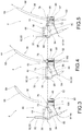
figure 3 is a view of the system infigure 1a in which only the front brake is actuated; -
figure 4 is a view of the system infigure 1a in which only the rear brake is actuated; -
figure 5 is a view of the system infigure 1a in which, following the actuation of the rear brake alone, the front brake is also actuated, obtaining a combined braking; -
figure 6 shows a schematic view of a vehicle comprising a braking system according to the present invention. - Elements or parts of elements in common to the embodiments described below are referred to with the same reference numerals.
- With reference to the above figures,
reference numeral 4 indicates as a whole an overall schematic view of a combined braking system according to the present invention. - For the purposes of the present invention, it should be noted that the braking system may be applied to vehicles 6 generally not necessarily powered, comprising cycles, motorcycles and vehicles with three or more wheels, as better described hereinafter.
- The combined
braking system 4 comprises at least a first braking device 8 operatively connected to afront wheel 12 placed on afirst axle 16 of the vehicle 6 and at least asecond braking device 20 operatively connected to arear wheel 24 placed on asecond axle 28 of the vehicle 6. - For the purposes of the present invention, the
braking devices 8, 20 may be of any type; preferably, the first andsecond braking devices 8, 20 are drum brakes. - Moreover, preferably, but not necessarily, the
first axle 16 is a front axle of the vehicle 6, which supports at least onefront wheel 12 of the vehicle and thesecond axle 28 is a rear axle of the vehicle 6 which supports at least onerear wheel 24 of the vehicle 6. - Moreover, the
braking system 4 comprises a first actuatingcable 32 operatively connected to the first braking device 8 and to a firstmanual actuating lever 33, a second actuatingcable 36 which can be operatively connected to thesecond braking device 20 and to a secondmanual actuating lever 34. - The actuating
cables lever lever - Typically, each
actuating cable - Moreover, the
braking system 4 comprises aninterconnection mechanism 40 between the first and second actuatingcables interconnection mechanism 40 serves to suitably interconnect the operation or rather the actuation of thebraking devices 8, 20 so as to obtain the combined braking of the vehicle 6. - The
interconnection mechanism 40 comprises a first rotatingelement 44 connected to the first actuatingcable 32 so as to actuate the first braking device 8, when rotated under the traction action of said first actuatingcable 32, - The traction action of the first actuating
cable 32 is exerted by the user by acting on the first actuating lever orpedal 33. - The
interconnection mechanism 40 further comprises a fixed support comprising afixed abutment 52 and a second rotatingelement 56, crossed by the second actuatingcable 36. - In particular, the second rotating
element 56 is influenced in rotation by the traction action of the second actuatingcable 36, by the manual action of the user on the second actuating lever orpedal 34, and is configured so as to intercept the first rotatingelement 44 and rotate it to also actuate the first braking device 8. - At the same time, the
interconnection mechanism 40 is shaped so that the rotation of the first rotatingelement 44 by means of the first actuatingcable 32 does not influence in rotation the secondrotating element 56. - In this way, by manually acting on the first manual actuating lever or
pedal 33, only thefirst braking device 20 is actuated; conversely, by manually acting on the second manual actuating lever orpedal 34, thesecond braking device 20 is mainly actuated and the first braking device 8 is also secondarily actuated. - Preferably, elastic contrast means 60 are interposed between the
fixed abutment 52 and the second rotatingelement 56, which influence the secondrotating y element 56 away from the first rotatingelement 44 to counteract the influence of the second rotatingelement 56 on the first rotatingelement 44. - In other words, the thrust action exerted by the elastic contrast means 60, as long as it prevails over the forces acting on the second rotating
element 56, mechanically disengages the first and second rotatingelements element 56 overcome the action of the elastic contrast means 60, then the rotation of the second rotatingelement 56, consequent to the actuation of thesecond braking device 20 by the second manual actuatingn lever 34 causes the rotation of the first rotatingelement 44 and therefore also the actuation of the first braking device 8. - To this end, the second rotating
element 56, in the rest configuration or when not in use, is resting on said first rotatingelement 44 so as to rotate, dragging with it in rotation the firstrotating element 44, when it overcomes the contrast action of the elastic contrast means 60. For example, said elastic contrast means 60 comprise a coil spring wound around the second actuatingcable 36. - The second actuating
cable 36 is a Bowden cable having awire 64 slidingly housed in anouter sheath 68. The wire is typically a steel wire consisting of one or more twisted, steel strands. Theouter sheath 68 is preferably internally lined with anti-friction material, such as Teflon, to facilitate the sliding of thewire 64 therein. - The
outer sheath 68 is abutted against the second rotatingelement 56 and against asupport 37 of the second manual actuatingn lever 34, so as to exert a reaction thrust on said second rotatingelement 56, when thewire 64 of the second actuatingcable 36 is pulled. - In other words, by pulling the second actuating
cable 36 through the second actuatinglever 34, thewire 64 slides inside theouter sheath 68 and, in doing so, it activates the correspondingsecond braking device 20. At the same time, theouter sheath 68 of the second actuatingcable 36, being constrained to thesupport 37 of the second actuatinglever 34 and to the second rotatingelement 56, cannot slide and is forced to deform elastically, thereby releasing the reaction on the second rotatingelement 56 . - In this way, the
outer sheath 68 of the second actuatingcable 36 is able to exert a reaction thrust on the second rotatingelement 56. - Initially this reaction on the second rotating
element 56 is in turn countered and overcome by the elastic contrast means 60 which tend to move the second rotatingelement 56 away from the first rotatingelement 44. When the reaction on the second rotatingelement 56 overcomes the elastic action of the elastic contrast means 60, following an increase in the sliding of thewire 64, i.e. a greater actuation by the user of the secondmanual actuating lever 34, then the second rotatingelement 56 abuts against the first rotatingelement 44 and moves it in rotation, thus generating the actuation of the first braking device 8, without the user having exerted any action on the firstmanual actuating lever 33. - According to a preferred embodiment, the first and second rotating
elements same fulcrum 72. - The second rotating
element 56 comprises a pair ofarms fulcrum 72, wherein afirst arm 76 is influenced by theouter sheath 68 of the second actuatingcable 36 and asecond arm 80 is configured to influence in rotation the firstrotating element 44. - The
second arm 80 is, for example, provided with acylindrical thrust pin 84 on acorresponding abutment 88 of the first rotatingelement 44. - For example, the
abutment 88 of the first rotatingelement 44 is concave towards thecylindrical pin 84 so as to be counter-shaped with respect to the latter. Moreover, such a cylindrical coupling facilitates reciprocal rotation between the first and the secondrotating elements interconnection mechanism 40. In a particular embodiment of the invention (not shown), thecylindrical pin 84 moves within an eyelet configured in such a way that thepin 84 is in abutment with said eyelet when the braking system is at rest, i.e. not actuated. - Preferably, the first actuating
cable 32 is a Bowden cable having anouter sheath 68 and a tie-rod 92, said tie-rod 92 being divided into two pieces 93, 94. - According to a possible embodiment, the first piece 93 is connected to both the first rotating
element 44, by means of apin 96 and aslot 98 in which thepin 96 slides, and to the firstmanual actuating lever 33; the second piece 94 is connected to the first braking device 8, preferably without clearance. - According to a further possible embodiment, the first actuating
cable 32 is a Bowden cable having anouter sheath 68 and a tie-rod 92 divided into two pieces 93, 94; the first piece 93 is connected both to the first rotatingelement 44 and to the first actuatinglever 33; the second piece 94 is connected to the first braking device 8. - According to an embodiment, the first piece 93 is connected to the first rotating
element 44 by means of apin 96 which engages on aslot 98; in this configuration, the second piece 94 is connected to the first braking device 8 and to the first rotatingelement 44 without clearance. - According to a further embodiment (
figure 1b ), the first piece 93 is connected to the firstrotating element 44 without clearance, while a clearance is provided between the firstmanual lever 33 and arelative support 39 of the first manual lever 33: this clearance can also in this case be obtained by means of a coupling with a pin which engages on a slot. The clearance serves to allow the extension of the first piece 93 when, following the actuation of the secondmanual lever 34, the secondrotating element 56 also rotates the firstrotating element 44, without the user having in turn actuated the firstmanual lever 33. - In general, between at least one of said first and second pieces 93, 94 and the first
rotating element 44 there should be a connection allowing an overall relative stroke between thefirst actuating cable 32 and the firstrotating element 44 when, following the actuation of the secondmanual lever 34, the secondrotating element 56 also rotates the firstrotating element 44. - Preferably, said
slot 98 has an extension or stroke not less than the displacement or stroke of the secondrotating element 56 under the dragging action of the firstrotating element 44. - The stroke between the
pin 96 and therelative slot 98 serves to allow the traction of the second piece 94 of the tie-rod 92 and therefore the activation of the first braking device 8, even without having actuated the firstmanual actuating lever 33. According to a further embodiment, theinterconnection mechanism 40 comprises anend stop 100 which limits the rotation stroke of thefirst arm 76 of the secondrotating element 56 in the event of a fault or breakage of the second piece 94 of thefirst actuating cable 32. In fact, in case of fault of the second piece 94 of thefirst actuating cable 32, the firstrotating element 44 would be idle and the secondrotating element 56 would only encounter the resistance of the elastic contrast means 60 and no longer the thrust exerted by said second piece 94. Due to theend stop 100, the driver does not perceive the brake of therear wheel 24 as too soft or even as not working. - The operation of a combined brake system according to the present invention shall now be described.
- In particular, if the first
manual actuating lever 33 is actuated, the braking system is able to perform a conventional braking action (figure 3 ), that is, to actuate only the corresponding first braking device 8 in a known manner. - In particular, the
wire 64 of thefirst actuating cable 32 is driven by the firstmanual actuating lever 33 and therefore generates the rotation of the first rotating element alone which, due to the second section 94, activates the corresponding first braking device 8. In this condition, the secondrotating element 56 is in no way influenced and the braking does not involve thesecond braking device 20. - If the second manual actuating
lever 34 is actuated, the braking system is capable of both performing a single braking of the corresponding second braking device (figure 4 ) and a combined braking (figure 5 ). - In particular, during the first stroke of the second manual actuating
lever 34,
thesecond actuating cable 36 is pulled, thewire 64 slides inside theouter sheath 68 and, in doing so, it activates the correspondingsecond braking device 20. At the same time, theouter sheath 68 of thesecond actuating cable 36 is constrained to thesecond actuating lever 34 and therefore cannot in turn move or slide. For this reason, theouter sheath 68 of thesecond actuating cable 36 tends to stretch elastically, thus releasing the reaction on the secondrotating element 56. - Initially this reaction on the second
rotating element 56 is in turn countered and overcome by the elastic contrast means 60 which tend to move the secondrotating element 56 away from the first rotating element 44 (figure 4 ). - In this condition, the braking is still conventional, as it involves only the
second braking device 20. - When the reaction on the second
rotating element 56 overcomes the elastic action of the elastic contrast means 60, following an increase in the sliding of thewire 64, i.e. a greater actuation by the user of the second manual actuatinglever 34, then the secondrotating element 56 abuts against the firstrotating element 44 and moves it in rotation, thus generating the actuation of the first braking device 8, without the user having exerted any action on the firstmanual actuating lever 33. This operation represents a braking of the combined type, since even if acting on a single manual actuating lever acting on a braking device, the activation also of a separate braking device is obtained, not directly connected to said single manual actuating lever. - It should be noted that in the combined operation, the stroke between the
pin 96 and therelative slot 98 serves to allow the traction of the second piece 94 of the tie-rod 92 and therefore the activation of the first braking device 8, even without having actuated the firstmanual actuating lever 33. - It should also be noted that the
interconnection mechanism 40 is configured so as to function both in case of fault of the second piece 94 of thefirst actuating cable 32 and in the event of a fault in the cable or rear wire 64: in this way, the braking of the vehicle by means of the brake not affected is always possible. - As can be appreciated from the description, the present invention allows overcoming the drawbacks of the prior art.
- In particular, the braking system is particularly simple and cost-effective from a mechanical point of view.
- However, the braking system always ensures combined braking in a reliable and safe manner.
- The interconnection mechanism is in fact able to guarantee both single (conventional) braking and combined braking.
- The braking system can also be easily calibrated according to the user's needs, by acting appropriately on the preload of the contrast spring and/or the sizing of the corresponding rotating transmissions.
- The present invention lends itself to being effectively applied to cycles, motorcycles and to any motorized motor vehicle also as back-fitting, i.e. as an adaptation of a pre-existing braking system.
- A man skilled in the art, in order to meet contingent and specific requirements, may make several modifications and variants to the brake systems described above, all of which fall within the scope of the invention as defined by the following claims.
Claims (15)
- Combined braking system (4) for vehicles (6) comprising:- at least a first braking device (8) operatively connected to a front wheel (12) of the vehicle (6),- at least a second braking device (20) operatively connected to a rear wheel (24) of the vehicle (6),- a first actuating cable (32) operatively connected to the first braking device (8) which can be connected to a first actuating lever (33), a second actuating cable (36) which can be operatively connected to the second braking device (20) and to a second actuating lever (34),- an interconnection mechanism (40) between the first and second actuating cables (32,36) comprising:wherein the second actuating cable (36) is a Bowden cable having a wire (64) slidingly housed in an outer sheath (68), characterized in that the outer sheath (68) is abutting against the second rotating element (56) so as to exert a reaction thrust on said second rotating element (56) when the wire (64) of the second actuating cable (36) is pulled by said second lever (34).- a first rotating element (44) connected to the first actuating cable (32) in order to actuate the first braking device (8) when rotated,- a second rotating element (56) configured to intercept the first rotating element (44) and rotate it to actuate the first braking device (8), influenced in rotation by the traction action exerted on the second actuating cable (36) by said second actuating lever (34),
- Combined braking system (4) according to claim 1, in which the second rotating element (56) is moved away from a fixed abutment (52) and from the first rotating element (44) by elastic contrast means (60).
- Combined braking system (4) according to claim 2, in which said elastic contrast means (60) comprise a coil spring wound around the second actuating cable (36).
- Combined braking system (4) according to claim 2 or 3, wherein said reaction thrust of the outer sheath (68) of the second actuating cable (36) is countered by elastic contrast means (60).
- Combined braking system (4) according to any of the claims from 1 to 4, wherein the second rotating element (56), in the rest configuration or when not in use, is resting on said first rotating element (44) so as to rotate, dragging with it in rotation the first rotating element (44), when the reaction thrust of the outer sheath (68) of the second actuating cable (36) overcomes the contrast action of the elastic contrast means (60).
- Combined braking system (4) according to any one of the claims from 1 to 5, wherein the first and second rotating elements (44, 56) are hinged on the same fulcrum (72).
- Combined braking system (4) according to any of the preceding claims, wherein the second rotating element (56) comprises a pair of arms (76, 80) opposite each other with respect to the fulcrum (72), the first arm (76) being influenced by an outer sheath (68) of the second actuating cable (36), the second arm (80) being configured to influence in rotation the first rotating element (44).
- Combined braking system (4) according to claim 7, wherein said second arm (80) is provided with a cylindrical thrust pin (84) on an abutment (88) of the first rotating element (44).
- Combined braking system (4) according to any of the claims from 7 to 8, wherein the interconnection mechanism (40) comprises an end stop (100) which limits the stroke in rotation of the second rotating element (56).
- Combined braking system (4) according to any one of the claims from 1 to 9, wherein the first actuating cable (32) comprises a tie-rod (92) divided into two pieces (93, 94), wherein a first piece (93) is connected both to the first rotating element (44), by means of a pin (96) and a slot (98) in which the pin (96) slides, and to the first manual actuating lever (33), and wherein the second piece (94) is connected to the first braking device (8) and to the first rotating element (44) without clearance.
- Combined braking system (4) according to any one of the claims from 1 to 9, wherein the first actuating cable (32) comprises a tie-rod (92) divided into two pieces (93, 94), wherein the first piece (93) is connected to the first rotating element (44) without clearance, while clearance is provided between the first manual lever (33) and a relative support (39) of the first manual lever (33).
- Combined braking system (4) according to claim 10 or 11, wherein said slot (98) has an extension or stroke no less than the displacement or stroke of the second rotating element (56) when rotated by the first rotating element (44).
- Combined braking system (4) according to any one of the claims from 1 to 12, wherein the interconnection mechanism (40) is shaped so that the rotation of the first rotating element (44) by means of the first actuating cable (32) does not influence in rotation the second rotating element (56).
- Vehicle (6) comprising a braking system (4) according to any of the claims from 1 to 13, in particular wherein said vehicle (6) is a bicycle or motorcycle.
- Vehicle (6) according to claim 14, wherein the first and second braking devices (8, 20) are drum brakes.
Applications Claiming Priority (2)
| Application Number | Priority Date | Filing Date | Title |
|---|---|---|---|
| IT201700133654 | 2017-11-22 | ||
| PCT/IB2018/059183 WO2019102375A1 (en) | 2017-11-22 | 2018-11-21 | Combined braking system for vehicles, especially for motorcycles |
Publications (2)
| Publication Number | Publication Date |
|---|---|
| EP3713824A1 EP3713824A1 (en) | 2020-09-30 |
| EP3713824B1 true EP3713824B1 (en) | 2021-11-24 |
Family
ID=61527374
Family Applications (1)
| Application Number | Title | Priority Date | Filing Date |
|---|---|---|---|
| EP18811663.6A Active EP3713824B1 (en) | 2017-11-22 | 2018-11-21 | Combined braking system for vehicles, especially for motorcycles |
Country Status (3)
| Country | Link |
|---|---|
| EP (1) | EP3713824B1 (en) |
| TW (1) | TWI758564B (en) |
| WO (1) | WO2019102375A1 (en) |
Family Cites Families (7)
| Publication number | Priority date | Publication date | Assignee | Title |
|---|---|---|---|---|
| JP4090593B2 (en) * | 1998-10-20 | 2008-05-28 | 日信工業株式会社 | Bar handle vehicle brake system |
| JP4206181B2 (en) * | 1999-12-15 | 2009-01-07 | 本田技研工業株式会社 | Interlocking brake device |
| JP2004345508A (en) * | 2003-05-22 | 2004-12-09 | Nippon Cable Syst Inc | Combination brake system for motorcycle |
| JP4344541B2 (en) * | 2003-05-30 | 2009-10-14 | 本田技研工業株式会社 | Interlocking brake device for small vehicles |
| JP5860856B2 (en) * | 2013-08-29 | 2016-02-16 | 日信工業株式会社 | Bar handle vehicle brake system |
| JP2017043108A (en) * | 2013-12-24 | 2017-03-02 | 日信工業株式会社 | Bar handle vehicle brake system |
| TWI582007B (en) * | 2016-02-25 | 2017-05-11 | 三陽工業股份有限公司 | Linked brake system |
-
2018
- 2018-11-21 EP EP18811663.6A patent/EP3713824B1/en active Active
- 2018-11-21 WO PCT/IB2018/059183 patent/WO2019102375A1/en not_active Ceased
- 2018-11-22 TW TW107141640A patent/TWI758564B/en not_active IP Right Cessation
Also Published As
| Publication number | Publication date |
|---|---|
| TWI758564B (en) | 2022-03-21 |
| TW201925016A (en) | 2019-07-01 |
| EP3713824A1 (en) | 2020-09-30 |
| WO2019102375A1 (en) | 2019-05-31 |
Similar Documents
| Publication | Publication Date | Title |
|---|---|---|
| US4644816A (en) | Brake actuator | |
| US4286699A (en) | Dual function handgrip control | |
| EP2301815B1 (en) | Parking brake device for motorcycle | |
| JP5907639B2 (en) | Brake device for motorcycle | |
| US8881878B2 (en) | Brake device for motorcycle | |
| US5370017A (en) | Handlebar cable control with biased return feature | |
| KR102176060B1 (en) | Drum brake apparatus for vehicle | |
| CN104229049A (en) | Bicycle handlebar assembly with integrated oleo-hydraulic controls | |
| WO2019102375A1 (en) | Combined braking system for vehicles, especially for motorcycles | |
| CA1104470A (en) | Brake pedal linkage mechanism | |
| JP2015186954A (en) | Brake device for bar handle vehicle | |
| BR112019017623B1 (en) | PEDAL OPERATED SYNCHRONIZED BRAKING SYSTEM | |
| EP3752397B1 (en) | Combined front/rear braking system for a vehicle and vehicle equipped with such a braking system | |
| EP2857303B1 (en) | Time difference safety brake | |
| US1000113A (en) | Vehicle-brake. | |
| JP2018021657A (en) | Vehicle drum brake device and vehicle equipped with the same | |
| EP3604057B1 (en) | Vehicle brake system and vehicle including same brake system | |
| US20260091843A1 (en) | Energy-saving brake lever assembly for vehicles | |
| US550067A (en) | Vehicle-brake | |
| CN104802773A (en) | Braking device for vehicle, and anti-lock braking system | |
| JP6322009B2 (en) | Bar handle vehicle brake system | |
| US1295226A (en) | Brake-operating attachment for automobiles. | |
| CN106926964B (en) | Safety brake device | |
| KR101612371B1 (en) | Clutch pedal effort reduction structure | |
| WO2026047714A1 (en) | A braking system for a vehicle |
Legal Events
| Date | Code | Title | Description |
|---|---|---|---|
| STAA | Information on the status of an ep patent application or granted ep patent |
Free format text: STATUS: UNKNOWN |
|
| STAA | Information on the status of an ep patent application or granted ep patent |
Free format text: STATUS: THE INTERNATIONAL PUBLICATION HAS BEEN MADE |
|
| PUAI | Public reference made under article 153(3) epc to a published international application that has entered the european phase |
Free format text: ORIGINAL CODE: 0009012 |
|
| STAA | Information on the status of an ep patent application or granted ep patent |
Free format text: STATUS: REQUEST FOR EXAMINATION WAS MADE |
|
| 17P | Request for examination filed |
Effective date: 20200513 |
|
| AK | Designated contracting states |
Kind code of ref document: A1 Designated state(s): AL AT BE BG CH CY CZ DE DK EE ES FI FR GB GR HR HU IE IS IT LI LT LU LV MC MK MT NL NO PL PT RO RS SE SI SK SM TR |
|
| AX | Request for extension of the european patent |
Extension state: BA ME |
|
| DAV | Request for validation of the european patent (deleted) | ||
| DAX | Request for extension of the european patent (deleted) | ||
| GRAP | Despatch of communication of intention to grant a patent |
Free format text: ORIGINAL CODE: EPIDOSNIGR1 |
|
| STAA | Information on the status of an ep patent application or granted ep patent |
Free format text: STATUS: GRANT OF PATENT IS INTENDED |
|
| INTG | Intention to grant announced |
Effective date: 20210621 |
|
| GRAS | Grant fee paid |
Free format text: ORIGINAL CODE: EPIDOSNIGR3 |
|
| GRAA | (expected) grant |
Free format text: ORIGINAL CODE: 0009210 |
|
| STAA | Information on the status of an ep patent application or granted ep patent |
Free format text: STATUS: THE PATENT HAS BEEN GRANTED |
|
| AK | Designated contracting states |
Kind code of ref document: B1 Designated state(s): AL AT BE BG CH CY CZ DE DK EE ES FI FR GB GR HR HU IE IS IT LI LT LU LV MC MK MT NL NO PL PT RO RS SE SI SK SM TR |
|
| REG | Reference to a national code |
Ref country code: GB Ref legal event code: FG4D |
|
| REG | Reference to a national code |
Ref country code: AT Ref legal event code: REF Ref document number: 1449672 Country of ref document: AT Kind code of ref document: T Effective date: 20211215 |
|
| REG | Reference to a national code |
Ref country code: DE Ref legal event code: R096 Ref document number: 602018027254 Country of ref document: DE |
|
| REG | Reference to a national code |
Ref country code: IE Ref legal event code: FG4D |
|
| REG | Reference to a national code |
Ref country code: LT Ref legal event code: MG9D |
|
| REG | Reference to a national code |
Ref country code: NL Ref legal event code: MP Effective date: 20211124 |
|
| REG | Reference to a national code |
Ref country code: AT Ref legal event code: MK05 Ref document number: 1449672 Country of ref document: AT Kind code of ref document: T Effective date: 20211124 |
|
| PG25 | Lapsed in a contracting state [announced via postgrant information from national office to epo] |
Ref country code: RS Free format text: LAPSE BECAUSE OF FAILURE TO SUBMIT A TRANSLATION OF THE DESCRIPTION OR TO PAY THE FEE WITHIN THE PRESCRIBED TIME-LIMIT Effective date: 20211124 Ref country code: LT Free format text: LAPSE BECAUSE OF FAILURE TO SUBMIT A TRANSLATION OF THE DESCRIPTION OR TO PAY THE FEE WITHIN THE PRESCRIBED TIME-LIMIT Effective date: 20211124 Ref country code: FI Free format text: LAPSE BECAUSE OF FAILURE TO SUBMIT A TRANSLATION OF THE DESCRIPTION OR TO PAY THE FEE WITHIN THE PRESCRIBED TIME-LIMIT Effective date: 20211124 Ref country code: BG Free format text: LAPSE BECAUSE OF FAILURE TO SUBMIT A TRANSLATION OF THE DESCRIPTION OR TO PAY THE FEE WITHIN THE PRESCRIBED TIME-LIMIT Effective date: 20220224 Ref country code: AT Free format text: LAPSE BECAUSE OF FAILURE TO SUBMIT A TRANSLATION OF THE DESCRIPTION OR TO PAY THE FEE WITHIN THE PRESCRIBED TIME-LIMIT Effective date: 20211124 |
|
| PG25 | Lapsed in a contracting state [announced via postgrant information from national office to epo] |
Ref country code: IS Free format text: LAPSE BECAUSE OF FAILURE TO SUBMIT A TRANSLATION OF THE DESCRIPTION OR TO PAY THE FEE WITHIN THE PRESCRIBED TIME-LIMIT Effective date: 20220324 Ref country code: SE Free format text: LAPSE BECAUSE OF FAILURE TO SUBMIT A TRANSLATION OF THE DESCRIPTION OR TO PAY THE FEE WITHIN THE PRESCRIBED TIME-LIMIT Effective date: 20211124 Ref country code: PT Free format text: LAPSE BECAUSE OF FAILURE TO SUBMIT A TRANSLATION OF THE DESCRIPTION OR TO PAY THE FEE WITHIN THE PRESCRIBED TIME-LIMIT Effective date: 20220324 Ref country code: PL Free format text: LAPSE BECAUSE OF FAILURE TO SUBMIT A TRANSLATION OF THE DESCRIPTION OR TO PAY THE FEE WITHIN THE PRESCRIBED TIME-LIMIT Effective date: 20211124 Ref country code: NO Free format text: LAPSE BECAUSE OF FAILURE TO SUBMIT A TRANSLATION OF THE DESCRIPTION OR TO PAY THE FEE WITHIN THE PRESCRIBED TIME-LIMIT Effective date: 20220224 Ref country code: NL Free format text: LAPSE BECAUSE OF FAILURE TO SUBMIT A TRANSLATION OF THE DESCRIPTION OR TO PAY THE FEE WITHIN THE PRESCRIBED TIME-LIMIT Effective date: 20211124 Ref country code: LV Free format text: LAPSE BECAUSE OF FAILURE TO SUBMIT A TRANSLATION OF THE DESCRIPTION OR TO PAY THE FEE WITHIN THE PRESCRIBED TIME-LIMIT Effective date: 20211124 Ref country code: HR Free format text: LAPSE BECAUSE OF FAILURE TO SUBMIT A TRANSLATION OF THE DESCRIPTION OR TO PAY THE FEE WITHIN THE PRESCRIBED TIME-LIMIT Effective date: 20211124 Ref country code: GR Free format text: LAPSE BECAUSE OF FAILURE TO SUBMIT A TRANSLATION OF THE DESCRIPTION OR TO PAY THE FEE WITHIN THE PRESCRIBED TIME-LIMIT Effective date: 20220225 |
|
| PG25 | Lapsed in a contracting state [announced via postgrant information from national office to epo] |
Ref country code: SM Free format text: LAPSE BECAUSE OF FAILURE TO SUBMIT A TRANSLATION OF THE DESCRIPTION OR TO PAY THE FEE WITHIN THE PRESCRIBED TIME-LIMIT Effective date: 20211124 Ref country code: SK Free format text: LAPSE BECAUSE OF FAILURE TO SUBMIT A TRANSLATION OF THE DESCRIPTION OR TO PAY THE FEE WITHIN THE PRESCRIBED TIME-LIMIT Effective date: 20211124 Ref country code: RO Free format text: LAPSE BECAUSE OF FAILURE TO SUBMIT A TRANSLATION OF THE DESCRIPTION OR TO PAY THE FEE WITHIN THE PRESCRIBED TIME-LIMIT Effective date: 20211124 Ref country code: ES Free format text: LAPSE BECAUSE OF FAILURE TO SUBMIT A TRANSLATION OF THE DESCRIPTION OR TO PAY THE FEE WITHIN THE PRESCRIBED TIME-LIMIT Effective date: 20211124 Ref country code: EE Free format text: LAPSE BECAUSE OF FAILURE TO SUBMIT A TRANSLATION OF THE DESCRIPTION OR TO PAY THE FEE WITHIN THE PRESCRIBED TIME-LIMIT Effective date: 20211124 Ref country code: DK Free format text: LAPSE BECAUSE OF FAILURE TO SUBMIT A TRANSLATION OF THE DESCRIPTION OR TO PAY THE FEE WITHIN THE PRESCRIBED TIME-LIMIT Effective date: 20211124 Ref country code: CZ Free format text: LAPSE BECAUSE OF FAILURE TO SUBMIT A TRANSLATION OF THE DESCRIPTION OR TO PAY THE FEE WITHIN THE PRESCRIBED TIME-LIMIT Effective date: 20211124 |
|
| REG | Reference to a national code |
Ref country code: DE Ref legal event code: R097 Ref document number: 602018027254 Country of ref document: DE |
|
| PLBE | No opposition filed within time limit |
Free format text: ORIGINAL CODE: 0009261 |
|
| STAA | Information on the status of an ep patent application or granted ep patent |
Free format text: STATUS: NO OPPOSITION FILED WITHIN TIME LIMIT |
|
| PG25 | Lapsed in a contracting state [announced via postgrant information from national office to epo] |
Ref country code: AL Free format text: LAPSE BECAUSE OF FAILURE TO SUBMIT A TRANSLATION OF THE DESCRIPTION OR TO PAY THE FEE WITHIN THE PRESCRIBED TIME-LIMIT Effective date: 20211124 |
|
| 26N | No opposition filed |
Effective date: 20220825 |
|
| PG25 | Lapsed in a contracting state [announced via postgrant information from national office to epo] |
Ref country code: SI Free format text: LAPSE BECAUSE OF FAILURE TO SUBMIT A TRANSLATION OF THE DESCRIPTION OR TO PAY THE FEE WITHIN THE PRESCRIBED TIME-LIMIT Effective date: 20211124 |
|
| PG25 | Lapsed in a contracting state [announced via postgrant information from national office to epo] |
Ref country code: IT Free format text: LAPSE BECAUSE OF FAILURE TO SUBMIT A TRANSLATION OF THE DESCRIPTION OR TO PAY THE FEE WITHIN THE PRESCRIBED TIME-LIMIT Effective date: 20211124 |
|
| PG25 | Lapsed in a contracting state [announced via postgrant information from national office to epo] |
Ref country code: MC Free format text: LAPSE BECAUSE OF FAILURE TO SUBMIT A TRANSLATION OF THE DESCRIPTION OR TO PAY THE FEE WITHIN THE PRESCRIBED TIME-LIMIT Effective date: 20211124 |
|
| REG | Reference to a national code |
Ref country code: CH Ref legal event code: PL |
|
| P01 | Opt-out of the competence of the unified patent court (upc) registered |
Effective date: 20230529 |
|
| GBPC | Gb: european patent ceased through non-payment of renewal fee |
Effective date: 20221121 |
|
| REG | Reference to a national code |
Ref country code: BE Ref legal event code: MM Effective date: 20221130 |
|
| PG25 | Lapsed in a contracting state [announced via postgrant information from national office to epo] |
Ref country code: LI Free format text: LAPSE BECAUSE OF NON-PAYMENT OF DUE FEES Effective date: 20221130 Ref country code: CH Free format text: LAPSE BECAUSE OF NON-PAYMENT OF DUE FEES Effective date: 20221130 |
|
| PG25 | Lapsed in a contracting state [announced via postgrant information from national office to epo] |
Ref country code: LU Free format text: LAPSE BECAUSE OF NON-PAYMENT OF DUE FEES Effective date: 20221121 |
|
| PG25 | Lapsed in a contracting state [announced via postgrant information from national office to epo] |
Ref country code: IE Free format text: LAPSE BECAUSE OF NON-PAYMENT OF DUE FEES Effective date: 20221121 Ref country code: GB Free format text: LAPSE BECAUSE OF NON-PAYMENT OF DUE FEES Effective date: 20221121 |
|
| PG25 | Lapsed in a contracting state [announced via postgrant information from national office to epo] |
Ref country code: BE Free format text: LAPSE BECAUSE OF NON-PAYMENT OF DUE FEES Effective date: 20221130 |
|
| PG25 | Lapsed in a contracting state [announced via postgrant information from national office to epo] |
Ref country code: CY Free format text: LAPSE BECAUSE OF FAILURE TO SUBMIT A TRANSLATION OF THE DESCRIPTION OR TO PAY THE FEE WITHIN THE PRESCRIBED TIME-LIMIT Effective date: 20211124 |
|
| PG25 | Lapsed in a contracting state [announced via postgrant information from national office to epo] |
Ref country code: MK Free format text: LAPSE BECAUSE OF FAILURE TO SUBMIT A TRANSLATION OF THE DESCRIPTION OR TO PAY THE FEE WITHIN THE PRESCRIBED TIME-LIMIT Effective date: 20211124 Ref country code: HU Free format text: LAPSE BECAUSE OF FAILURE TO SUBMIT A TRANSLATION OF THE DESCRIPTION OR TO PAY THE FEE WITHIN THE PRESCRIBED TIME-LIMIT; INVALID AB INITIO Effective date: 20181121 |
|
| PG25 | Lapsed in a contracting state [announced via postgrant information from national office to epo] |
Ref country code: TR Free format text: LAPSE BECAUSE OF FAILURE TO SUBMIT A TRANSLATION OF THE DESCRIPTION OR TO PAY THE FEE WITHIN THE PRESCRIBED TIME-LIMIT Effective date: 20211124 |
|
| PG25 | Lapsed in a contracting state [announced via postgrant information from national office to epo] |
Ref country code: MT Free format text: LAPSE BECAUSE OF FAILURE TO SUBMIT A TRANSLATION OF THE DESCRIPTION OR TO PAY THE FEE WITHIN THE PRESCRIBED TIME-LIMIT Effective date: 20211124 |
|
| PGFP | Annual fee paid to national office [announced via postgrant information from national office to epo] |
Ref country code: DE Payment date: 20241125 Year of fee payment: 7 |
|
| PGFP | Annual fee paid to national office [announced via postgrant information from national office to epo] |
Ref country code: FR Payment date: 20241025 Year of fee payment: 7 |