EP3040260A1 - Brake device for vehicle that has handlebars - Google Patents
Brake device for vehicle that has handlebars Download PDFInfo
- Publication number
- EP3040260A1 EP3040260A1 EP14839732.6A EP14839732A EP3040260A1 EP 3040260 A1 EP3040260 A1 EP 3040260A1 EP 14839732 A EP14839732 A EP 14839732A EP 3040260 A1 EP3040260 A1 EP 3040260A1
- Authority
- EP
- European Patent Office
- Prior art keywords
- brake
- lever
- rotary lever
- master cylinder
- hydraulic
- Prior art date
- Legal status (The legal status is an assumption and is not a legal conclusion. Google has not performed a legal analysis and makes no representation as to the accuracy of the status listed.)
- Granted
Links
Images







Classifications
-
- B—PERFORMING OPERATIONS; TRANSPORTING
- B60—VEHICLES IN GENERAL
- B60T—VEHICLE BRAKE CONTROL SYSTEMS OR PARTS THEREOF; BRAKE CONTROL SYSTEMS OR PARTS THEREOF, IN GENERAL; ARRANGEMENT OF BRAKING ELEMENTS ON VEHICLES IN GENERAL; PORTABLE DEVICES FOR PREVENTING UNWANTED MOVEMENT OF VEHICLES; VEHICLE MODIFICATIONS TO FACILITATE COOLING OF BRAKES
- B60T11/00—Transmitting braking action from initiating means to ultimate brake actuator without power assistance or drive or where such assistance or drive is irrelevant
- B60T11/10—Transmitting braking action from initiating means to ultimate brake actuator without power assistance or drive or where such assistance or drive is irrelevant transmitting by fluid means, e.g. hydraulic
- B60T11/16—Master control, e.g. master cylinders
- B60T11/18—Connection thereof to initiating means
-
- B—PERFORMING OPERATIONS; TRANSPORTING
- B60—VEHICLES IN GENERAL
- B60T—VEHICLE BRAKE CONTROL SYSTEMS OR PARTS THEREOF; BRAKE CONTROL SYSTEMS OR PARTS THEREOF, IN GENERAL; ARRANGEMENT OF BRAKING ELEMENTS ON VEHICLES IN GENERAL; PORTABLE DEVICES FOR PREVENTING UNWANTED MOVEMENT OF VEHICLES; VEHICLE MODIFICATIONS TO FACILITATE COOLING OF BRAKES
- B60T11/00—Transmitting braking action from initiating means to ultimate brake actuator without power assistance or drive or where such assistance or drive is irrelevant
- B60T11/04—Transmitting braking action from initiating means to ultimate brake actuator without power assistance or drive or where such assistance or drive is irrelevant transmitting mechanically
- B60T11/046—Using cables
-
- B—PERFORMING OPERATIONS; TRANSPORTING
- B60—VEHICLES IN GENERAL
- B60T—VEHICLE BRAKE CONTROL SYSTEMS OR PARTS THEREOF; BRAKE CONTROL SYSTEMS OR PARTS THEREOF, IN GENERAL; ARRANGEMENT OF BRAKING ELEMENTS ON VEHICLES IN GENERAL; PORTABLE DEVICES FOR PREVENTING UNWANTED MOVEMENT OF VEHICLES; VEHICLE MODIFICATIONS TO FACILITATE COOLING OF BRAKES
- B60T11/00—Transmitting braking action from initiating means to ultimate brake actuator without power assistance or drive or where such assistance or drive is irrelevant
- B60T11/10—Transmitting braking action from initiating means to ultimate brake actuator without power assistance or drive or where such assistance or drive is irrelevant transmitting by fluid means, e.g. hydraulic
- B60T11/102—Transmitting braking action from initiating means to ultimate brake actuator without power assistance or drive or where such assistance or drive is irrelevant transmitting by fluid means, e.g. hydraulic in combination with mechanical elements
-
- B—PERFORMING OPERATIONS; TRANSPORTING
- B60—VEHICLES IN GENERAL
- B60T—VEHICLE BRAKE CONTROL SYSTEMS OR PARTS THEREOF; BRAKE CONTROL SYSTEMS OR PARTS THEREOF, IN GENERAL; ARRANGEMENT OF BRAKING ELEMENTS ON VEHICLES IN GENERAL; PORTABLE DEVICES FOR PREVENTING UNWANTED MOVEMENT OF VEHICLES; VEHICLE MODIFICATIONS TO FACILITATE COOLING OF BRAKES
- B60T7/00—Brake-action initiating means
- B60T7/02—Brake-action initiating means for personal initiation
- B60T7/08—Brake-action initiating means for personal initiation hand actuated
- B60T7/10—Disposition of hand control
- B60T7/102—Disposition of hand control by means of a tilting lever
-
- B—PERFORMING OPERATIONS; TRANSPORTING
- B60—VEHICLES IN GENERAL
- B60T—VEHICLE BRAKE CONTROL SYSTEMS OR PARTS THEREOF; BRAKE CONTROL SYSTEMS OR PARTS THEREOF, IN GENERAL; ARRANGEMENT OF BRAKING ELEMENTS ON VEHICLES IN GENERAL; PORTABLE DEVICES FOR PREVENTING UNWANTED MOVEMENT OF VEHICLES; VEHICLE MODIFICATIONS TO FACILITATE COOLING OF BRAKES
- B60T8/00—Arrangements for adjusting wheel-braking force to meet varying vehicular or ground-surface conditions, e.g. limiting or varying distribution of braking force
- B60T8/26—Arrangements for adjusting wheel-braking force to meet varying vehicular or ground-surface conditions, e.g. limiting or varying distribution of braking force characterised by producing differential braking between front and rear wheels
- B60T8/261—Arrangements for adjusting wheel-braking force to meet varying vehicular or ground-surface conditions, e.g. limiting or varying distribution of braking force characterised by producing differential braking between front and rear wheels specially adapted for use in motorcycles
-
- B—PERFORMING OPERATIONS; TRANSPORTING
- B62—LAND VEHICLES FOR TRAVELLING OTHERWISE THAN ON RAILS
- B62L—BRAKES SPECIALLY ADAPTED FOR CYCLES
- B62L3/00—Brake-actuating mechanisms; Arrangements thereof
- B62L3/02—Brake-actuating mechanisms; Arrangements thereof for control by a hand lever
- B62L3/023—Brake-actuating mechanisms; Arrangements thereof for control by a hand lever acting on fluid pressure systems
-
- B—PERFORMING OPERATIONS; TRANSPORTING
- B62—LAND VEHICLES FOR TRAVELLING OTHERWISE THAN ON RAILS
- B62L—BRAKES SPECIALLY ADAPTED FOR CYCLES
- B62L3/00—Brake-actuating mechanisms; Arrangements thereof
- B62L3/08—Mechanisms specially adapted for braking more than one wheel
-
- F—MECHANICAL ENGINEERING; LIGHTING; HEATING; WEAPONS; BLASTING
- F16—ENGINEERING ELEMENTS AND UNITS; GENERAL MEASURES FOR PRODUCING AND MAINTAINING EFFECTIVE FUNCTIONING OF MACHINES OR INSTALLATIONS; THERMAL INSULATION IN GENERAL
- F16D—COUPLINGS FOR TRANSMITTING ROTATION; CLUTCHES; BRAKES
- F16D2125/00—Components of actuators
- F16D2125/18—Mechanical mechanisms
- F16D2125/58—Mechanical mechanisms transmitting linear movement
- F16D2125/60—Cables or chains, e.g. Bowden cables
-
- F—MECHANICAL ENGINEERING; LIGHTING; HEATING; WEAPONS; BLASTING
- F16—ENGINEERING ELEMENTS AND UNITS; GENERAL MEASURES FOR PRODUCING AND MAINTAINING EFFECTIVE FUNCTIONING OF MACHINES OR INSTALLATIONS; THERMAL INSULATION IN GENERAL
- F16D—COUPLINGS FOR TRANSMITTING ROTATION; CLUTCHES; BRAKES
- F16D2125/00—Components of actuators
- F16D2125/18—Mechanical mechanisms
- F16D2125/58—Mechanical mechanisms transmitting linear movement
- F16D2125/64—Levers
Definitions
- the present invention relates to a brake device for a bar handle vehicle, and more particularly to a brake device for a bar handle vehicle where either one of a front wheel brake and a rear wheel brake is formed of a hydraulic brake and the other brake is formed of a mechanical brake, the hydraulic brake is operated singly by operating a first brake operator, and the hydraulic brake and the mechanical brake are operated in an interlocking manner by operating a second brake operator.
- a brake device where at least one of a front wheel brake and a rear wheel brake is formed of a hydraulic brake, and the hydraulic brake is operated by operating a first brake operator through a master cylinder unit formed by combining a hydraulic master cylinder and a lever mechanism with each other.
- a master cylinder unit there has been known a combination of a master cylinder and a lever mechanism.
- the lever mechanism includes four levers consisting of a first rotary lever, a second rotary lever, a knocker lever and an equalizer lever.
- the hydraulic brake on one side is operated by the first rotary lever and the knocker rotated by operating the first brake operator, and both brakes are operated in an interlocking manner by an equalizer lever, the second rotary lever and the knocker (see patent literature 1, for example) rotated by operating the second brake operator.
- a delay spring which biases the second rotary lever about a rotary fulcrum in a non-operating direction is provided between the second rotary lever and a cylinder body.
- a body contact portion is formed on a distal end side of the second rotary lever, and an initial position of the second rotary lever is set by bringing the body contact portion into contact with an outer side surface of the cylinder body.
- the second rotary lever when the second rotary lever is rotated about the rotary fulcrum at the time of operating the second rotary lever, the other end side of the second rotary lever which projects toward the outside of the cylinder body largely projects to an outer peripheral side of the cylinder body. Accordingly, the master cylinder unit becomes large-sized. Further, there is a possibility that the distal end side of the second rotary lever is brought into contact with other parts during the operation so that the arrangement of the master cylinder unit is restricted.
- the present invention is directed to a brake device for a bar handle vehicle where either one of a front wheel brake and a rear wheel brake is formed of a hydraulic brake and the other brake is formed of a mechanical brake, the hydraulic brake is operated singly by operating a first brake operator by means of a master cylinder unit formed by combining a hydraulic master cylinder and a lever mechanism, the hydraulic brake and the mechanical brake are operated in an interlocking manner by operating a second brake operator by means of the master cylinder unit, the lever mechanism includes a first rotary lever, a second rotary lever, a knocker and an equalizer lever, a first brake connecting means connected to the first brake operator is connected to the first rotary lever, a piston of the hydraulic master cylinder is operated by operating the first brake operator by means of the knocker which the first rotary lever moves by pushing thus singly operating the hydraulic brake, a second brake connecting means connected to the second brake operator, a mechanical brake side connecting means connected to the mechanical brake and the second rotary lever are connected to the
- a lever holder which rotatably and pivotally supports the first rotary lever, the second rotary lever and the knocker by means of the fixing pin be mounted on a cylinder hole opening side of the cylinder body in a projecting manner, and the guide portion be formed on a projecting side end portion of the lever holder.
- the hydraulic master cylinder be a plunger-type hydraulic master cylinder.
- the guide portion which guides the mechanical brake side connecting means toward the equalizer lever is mounted on the cylinder body of the hydraulic master cylinder in a projecting manner, the second rotary lever contact surface brought into contact with the second rotary lever is formed on a cylinder body center axis side of the guide portion, the second rotary lever is biased so as to rotate in a non-operating direction about the fixing pin which forms a rotational fulcrum due to a repulsive force of the delay spring disposed between the second rotary lever and the cylinder body, and the guide portion contact surface which sets an initial position of the second rotary lever by being brought into contact with the second rotary lever contact surface is formed on the second rotary lever.
- the lever holder which rotatably and pivotally supports the first rotary lever, the second rotary lever and the knocker by means of the fixing pin is mounted on a cylinder hole opening side of the cylinder body in a projecting manner, and the guide portion is formed on a projecting side end portion of the lever holder.
- the first rotary lever, the second rotary lever, the knocker, and the guide portion can be arranged in a state where these parts are disposed close to a cylinder hole opening side and hence, the miniaturization of the master cylinder unit can be realized.
- the hydraulic master cylinder is a plunger-type hydraulic master cylinder. With such a configuration, a length of the cylinder body in a cylinder center axis direction can be decreased, and the further miniaturization of the master cylinder unit can be realized.
- a brake device 1 for a bar handle vehicle of this embodiment includes: a front wheel brake 2 and a rear wheel brake 3; a front-wheel-brake-use operator 4 (first brake operator of the present invention) ; and a rear-wheel-brake-use operator 5 (second brake operator of the present invention).
- a master cylinder unit 20 is interposed between the front wheel brake 2 and the front-wheel-brake-use operator 4 and between the rear wheel brake 3 and the rear-wheel-brake-use operator 5.
- a left side and a right side are a left side and a right side as viewed in a front view from a driver's side as shown in Fig. 1 . Accordingly, the explanation is made by assuming a front-wheel-brake-use operator 4 side as a right side and a rear-wheel-brake-use operator 5 side as a left side. Further, the description relating to a clockwise direction and a counterclockwise direction is also made by assuming these directions as directions as viewed in a front view in the same manner as described above.
- a hydraulic disk brake is used where a caliper body 2b provided with a piston is combined with a disc rotor 2a which rotates integrally with a front wheel.
- a mechanical drum brake is used where a pair of brake shoes 3b, 3b is arranged on a back plate 3a in an expandable and opposedly facing manner, and both brake shoes 3b, 3b can be expanded using an anchor pin 3c as a fulcrum.
- a second brake wire 9 (second brake connecting means of the present invention) is towed so that a rear-wheel-use brake wire 10 (mechanical-brake-side connecting means of the present invention) which operates the rear wheel brake 3 is towed through the master cylinder unit 20 whereby the rear wheel brake 3 is operated.
- Towing of the second brake wire 9 also operates a hydraulic master cylinder 21 of the master cylinder unit 20 so that a hydraulic pressure is supplied to the front wheel brake 2 through the hydraulic pressure pipe 8 thus operating the front wheel brake 2 in an interlocking manner with the operation of the rear wheel brake 3.
- the master cylinder unit 20 is formed by combining the hydraulic master cylinder 21 which supplies a hydraulic pressure to the front wheel brake 2 and a lever mechanism 40.
- the lever mechanism 40 includes a first rotary lever 41, a second rotary lever 42, a knocker 43 and an equalizer lever 44.
- a bottomed cylinder hole 21b is formed in a cylinder body 21a with an open lower end, and a union boss portion 21c is formed on a bottom portion side of the cylinder hole 21b in a projecting manner.
- a boss portion 21e provided with a fluid through hole 21d which communicates with the cylinder hole 21b is formed on a right side of the cylinder body 21a in a projecting manner.
- a connector 12 connected to a reservoir 11 by means of a seal member 12a is mounted on the boss portion 21e.
- a plunger 22 (piston of the present invention) is slidably inserted into the cylinder hole 21b by means of a first cup seal 23 and a second cup seal 24.
- the first cup seal 23 is fitted in a first seal groove 23a formed on an inner peripheral surface of the cylinder hole 21b on a side closer to a cylinder hole bottom portion than the fluid through hole 21d and adjacently to the fluid through hole 21d.
- the second cup seal 24 is fitted in a second seal groove 24a formed on the inner peripheral surface of the cylinder hole 21b on a side closer to a cylinder hole opening than the fluid through hole 21d and adjacently to the fluid through hole 21d.
- a hydraulic pressure chamber 25 is defined between a bottom portion of the cylinder hole 21b and the first cup seal 23.
- a replenishing chamber 21f which communicates with the first seal groove 23a, the second seal groove 24a and the fluid through hole 21d is formed on the inner peripheral surface of the cylinder hole 21b between the first seal groove 23a and the second seal groove 24a.
- a union hole 21g which opens in a bottom portion of the cylinder hole is formed in the union boss portion 21c.
- the hydraulic pressure pipe 8 is connected to the union boss portion 21c by means of a banjo bolt 26 and a banjo 27 mounted in the union hole 21g.
- the cylinder hole 21b and a caliper body 2b of the front wheel brake 2 communicate with each other through the hydraulic pressure pipe 8.
- the plunger 22 is formed of a bottomed cylindrical shape having a recessed portion 22a which opens on a cylinder hole bottom portion side.
- a plurality of communication ports 22b having a small diameter which penetrate the peripheral wall so as to communicate the inside and the outside of the peripheral wall with each other and make the hydraulic pressure chamber 25 and the replenishing chamber 21f communicate with each other at an initial position in a non-operative state are formed in a circumferential direction.
- a return spring 28 which makes the plunger 22 in a non-operative state return to a preset predetermined initial position is disposed.
- a small-diameter shaft portion 22d is formed on a sleeve portion 22c which slides in the cylinder hole 21b on a cylinder hole opening side.
- the plunger 22 is configured such that the small-diameter shaft portion 22d projects downward from a lower end opening of the cylinder body 21a, and a dustproof boot 30 is mounted between a distal end portion of the small-diameter shaft portion 22d and an outer surface of the circlip 29.
- an upper bracket 21h having a rectangular shape as viewed in a plan view is formed in a projecting manner toward a front side and a left side of the upper wall.
- the union boss portion 21c is arranged on a back surface side and a right side of the upper bracket 21h.
- a first wire guide portion 21i which guides the first brake wire 7 is arranged on a left side of the union boss portion 21c.
- a second wire guide portion 21j which guides the second brake wire 9 is arranged on a front side of the union boss portion 21c.
- a stopper bolt mounting portion 21k on which a stopper bolt 31 for restricting the rotation of the second rotary lever 42 is mounted is arranged on a left side of the second wire guide portion 21j.
- Vehicle body mounting brackets 21m, 21m which project toward a right side and a left lower side are formed on a back surface side of the upper bracket 21h in a projecting manner.
- a bolt hole 21n in which a vehicle body mounting bolt is mounted is formed in the vehicle body mounting brackets 21m, 21m respectively in a direction orthogonal to a cylinder center axis CL1.
- a spring mounting hole 21p in which a delay spring 32 is mounted is formed in a lower surface of the upper bracket 21h disposed between the first wire guide portion 21i and the stopper bolt mounting portion 21k.
- a pair of lever holders 21q, 21r is formed in a projecting manner on the cylinder body 21a on a front side and a back side in the vicinity of the cylinder hole opening portion.
- a through hole 21s and a female threaded hole 21t in which a fixing pin 33 is mounted are coaxially formed in the lever holders 21q, 21r.
- a rear-wheel-use brake wire guide portion 21u (guide portion of the present invention) is formed in a projecting manner on a lower end portion of the lever holder 21q on a front side.
- a second rotary lever contact surface 21v which sets an initial position of the second rotary lever 42 by coming into contact with the second rotary lever 42 is formed on a left side surface (a side surface on a cylinder body center axis side of the present invention) of the rear-wheel-use brake wire guide portion 21u.
- the stopper bolt 31 includes a shaft portion 31a provided with a male threaded portion, and a head portion 31c having a large-diameter seat surface 31b.
- the stopper bolt 31 is fixed using a nut member 31d in a state where the stopper bolt 31 is threaded into a female threaded hole formed in a stopper bolt mounting portion 21k, and the shaft portion 31a projects downward from the upper bracket 21h by a predetermined length.
- a bifurcated second rotary base portion 42b which is formed on the second rotary lever 42 is arranged between the lever holders 21q, 21r.
- a third rotary base portion 43a formed on the knocker 43 is arranged on a front side of an inner side of the second rotary base portion 42b.
- a first rotary base portion 41a formed on the first rotary lever 41 is arranged on a back surface side of the second rotary base portion 42b.
- the fixing pin 33 is inserted into and over the lever holders 21q, 21r, the first rotary base portion 41a, the second rotary base portion 42b and the third rotary base portion 43a, and the fixing pin 33 is fixed using a nut member 33a.
- the first rotary lever 41, the second rotary lever 42 and the knocker 43 are rotatably connected to the lever holders 21q, 21r by the following configuration. Further, on a front side of the lever holder 21q, an equalizer 44 is arranged above the rear-wheel-use brake wire guide portion 21u.
- An equalizer connecting arm 42c formed on the second rotary lever 42 and a second rotary lever connecting portion 44a formed on a left end portion of the equalizer lever 44 are rotatably and pivotally supported by means of a connecting pin 45 and a retainer ring 45a.
- the first rotary lever 41 is configured such that an adjustment bolt mounting portion 41c extends downward to an opening portion of the cylinder hole 21b from the first rotary base portion 41a provided with an insertion hole 41b for the fixing pin 33, an adjustment bolt 46 which comes into contact with the knocker 43 is mounted on a female threaded portion 41d of the adjustment bolt mounting portion 41c such that a projecting amount of the adjustment bolt 46 is adjustable using a nut member 46a.
- a first brake wire connecting portion 41e to which an end portion of the first brake wire 7 is connected is formed on a back surface side of the adjustment bolt mounting portion 41c.
- the second rotary lever 42 is formed into a block shape, and includes: the second rotary base portion 42d formed in a bifurcated shape and having a front side arm portion 42e and a back side arm portion 42f provided with an insertion hole 42d for the fixing pin 33 respectively; a connecting arm 42g projecting toward a front surface direction and extending in a left direction from a lower portion of the front side arm portion 42e; and an equalizer connecting arm 42c projecting upward from a left end portion of the connecting arm 42g.
- An insertion hole 42h for the connecting pin 45 is formed in the equalizer connecting arm 42c.
- a delay spring mounting portion 42i projecting in a back surface direction at a right angle is formed on an upper end portion of the equalizer connecting arm 42c in a projecting manner.
- the spring mounting boss 42a projecting toward the upper bracket 21h is formed on an upper surface of the delay spring mounting portion 42i in a projecting manner.
- a knocker pushing and moving surface 42j coming into contact with the knocker 43 and moving the knocker 43 by pushing is formed on a left lower portion of the back side arm portion 42f.
- a guide portion contact surface 42k is formed on an outer surface of a right end of the connecting arm 42g. The guide portion contact surface 42k comes into contact with a second rotary lever contact surface 21v formed on the rear-wheel-use brake wire guide portion 21u so as to set an initial position of the second rotary lever 42.
- the delay spring 32 is formed of a compression-type coil spring. An upper end side of the delay spring 32 is mounted in the spring mounting hole 21p formed in the upper bracket 21h, and a lower end side of the delay spring 32 is mounted on the spring mounting boss 42a of the second rotary lever 42.
- the knocker 43 is configured such that a plunger pushing and moving portion 43c which is constantly brought into contact with a lower end portion of the plunger 22 is formed on a left side of the third rotary base portion 43a provided with an insertion hole 43b for the fixing pin 33.
- a head portion 47a of a pin member 47 embedded in the knocker 43 is arranged on a lower surface of the plunger pushing and moving portion 43c, and an outer end surface of the head portion 47a forms an adjustment bolt contact surface 47b which is brought into contact with the adjustment bolt 46.
- a receiving surface 43d which is pushed and moved by the knocker pushing and moving surface 42j formed on the second rotary lever 42 is brought into contact with the knocker pushing and moving surface 42j with a slight clearance therebetween.
- the equalizer lever 44 is arranged on a front side of the cylinder body 21a.
- a rear-wheel-use brake wire connecting portion 44b to which the rear-wheel-use brake wire 10 is connected is formed on one end portion of the equalizer lever 44.
- a second brake wire connecting portion 44c to which the second brake wire 9 is connected is formed on a center portion of the equalizer lever 44.
- the second rotary lever connecting portion 44a which is connected to the equalizer connecting arm 42c of the second rotary lever 42 is formed on the other end portion of the equalizer lever 44.
- the second rotary lever connecting portion 44a is formed into a bifurcated shape where an insertion hole 44d of the connecting pin 45 is formed in the bifurcated portions respectively.
- the second rotary lever connecting portion 44a is rotatably connected to the equalizer connecting arm 42c by inserting the equalizer connecting arm 42c between portions of the second rotary lever connecting portion 44a, by inserting the connecting pin 45 into the insertion holes 44d, 44h and by mounting the retainer ring 45a on the connecting pin 45.
- the above-mentioned first rotary lever 41, second rotary lever 42, and knocker 43 are respectively rotatably connected between the lever holders 21q, 21r.
- the second rotary lever connecting portion 44a of the equalizer lever 44 is connected to the equalizer connecting arm 42c of the second rotary lever 42 by means of the connecting pin 45.
- the rear-wheel-use brake wire 10 which is towed by means of the rear-wheel-use brake wire guide portion 21u is connected to the rear-wheel-use brake wire connecting portion 44b of the equalizer lever 44, and the second brake wire 9 which is towed by means of the second wire guide portion 21j is connected to the second brake wire connecting portion 44c.
- the first brake wire 7 which is towed by means of the first wire guide portion 21i is connected to the first brake wire connecting portion 41e of the first rotary lever 41.
- the spring mounting boss 42a of the second rotary lever 42 is arranged on a left side of a center axis CL2 of the spring mounting hole 21p formed in the upper bracket 21h which is an outer peripheral side of the cylinder body.
- One end of the delay spring 32 is fitted into the inside of the spring mounting hole 21p, and the other end of the delay spring 32 is inserted into the spring mounting boss 42a.
- the delay spring 32 is arranged such that a lower end side of the delay spring 32 is inclined leftwardly, that is, in an outer peripheral direction of the cylinder body, with respect to the center axis CL2 of the spring mounting hole 21p.
- the plunger 22 of the hydraulic master cylinder 21 in a non-operative state, as shown in Fig. 1 to Fig. 10 , the plunger 22 of the hydraulic master cylinder 21 is brought into a state where the plunger 22 is biased in a direction toward the cylinder hole opening portion due to a repulsive force of the return spring 28, and an initial position of the plunger 22 is set by a contact between a stepped portion 22e of the plunger 22 and the circlip 29.
- An initial position of the first rotary lever 41 is held by a tension of the first brake wire 7 connected to the first brake wire connecting portion 41e.
- An initial position of the second rotary lever 42 is set in such a manner that a guide portion contact surface 42k is brought into contact with the second rotary lever contact surface 21v of the rear-wheel-use brake wire guide portion 21u due to a repulsive force of the delay spring 32.
- the second rotary lever contact surface 21v and the guide portion contact surface 42k are arranged parallel to the cylinder center axis CL1.
- the adjustment bolt contact surface 47b is brought into contact with a distal end portion of the adjustment bolt 46, and the receiving surface 43d is brought into contact with the knocker pushing and moving surface 42j with a slight clearance therebetween, and the plunger pushing and moving portion 43c is brought into contact with the plunger 22.
- the receiving surface 43d and the knocker pushing and moving surface 42j are respectively arranged parallel to a radial direction line D1 which passes the center of the fixing pin 33 in a non-operative state.
- the contact surface between the receiving surface 43d and the knocker pushing and moving surface 42j is arranged on the radial direction line D1 which passes the center of fixing pin 33.
- the equalizer lever 44 in a state where the second rotary lever connecting portion 44a is connected to the equalizer connecting arm 42c, a tension of the second brake wire 9 and a tension of the rear-wheel-use brake wire 10 are balanced with each other so that the equalizer lever 44 is held in a horizontal state.
- the delay spring 32 is in a state where the lower end side of the delay spring 32 is inclined leftward with respect to the center axis CL2 of the spring mounting hole 21p as viewed in a front view.
- the front-wheel-brake-use operator 4 When the front-wheel-brake-use operator 4 is operated from a non-operative state, as shown in Fig. 11 , the first brake wire 7 is towed, the first brake wire connecting portion 41e of the first rotary lever 41 is towed upward, and the first rotary lever 41 is rotated in a counterclockwise direction about the first rotary base portion 41a.
- the adjustment bolt 46 pushes and moves the adjustment bolt contact surface 47b of the knocker 43 thus rotating the knocker 43 in a counterclockwise direction about the third rotary base portion 43a so that the plunger pushing and moving portion 43c moves the plunger 22 by pushing.
- a working fluid whose fluid pressure is increased applies a fluid pressure to the front wheel brake 2 by means of the hydraulic pressure pipe 8 thus singly operating the front wheel brake 2.
- the second rotary lever 42 is rotated in a counterclockwise direction about the second rotary base portion 42b against a repulsive force of the delay spring 32.
- the knocker pushing and moving surface 42j is brought into contact with the receiving surface 43d of the knocker 43 and pushes and moves the receiving surface 43d of the knocker 43 so that the plunger 22 is pushed and moved. Accordingly, a working fluid whose pressure is increased applies a fluid pressure to the front wheel brake 2 by means of the hydraulic pressure pipe 8 thus operating the front wheel brake 2 in an interlocking manner with the operation of the rear wheel brake 3.
- the equalizer lever 44 is further towed upward and, at the same time, the second rotary lever 42 is rotated in the counterclockwise direction about the second rotary base portion 42b, the delay spring mounting portion 42i is brought into contact with a distal end of a shaft portion of the stopper bolt 31 so that the rotation of the delay spring mounting portion 42i is restricted, and the rotation of the knocker 43 is stopped so that the applying of a fluid pressure to the front wheel brake 2 is restricted.
- the delay spring 32 is operated such that, along with the rotation of the second rotary lever 42, a center line of the delay spring 32 is temporarily arranged on the center axis CL2 of the spring mounting hole 21p and, thereafter, the delay spring 32 is brought into a state where a lower end side of the delay spring 32 is inclined rightward (toward the cylinder center axis CL1) with respect to the center axis CL2.
- the rear wheel brake is operated as follows. That is, the delay spring mounting portion 42i is brought into contact with the distal end of the shaft portion of the stopper bolt 31 so that the rotation of the second rotary lever 42 is restricted whereby the position of the connecting pin 45 is fixed. Accordingly, the equalizer lever 44 is rotated in a clockwise direction about the connecting pin 45, and only the rear-wheel-use brake wire 10 is towed so that the rear wheel brake 3 is operated further strongly.
- the delay spring mounting portion 42i is brought into contact with the distal end of the shaft portion of the stopper bolt 3 so that the second rotary lever 42 is brought into a state where the rotation of the second rotary lever 42 is restricted and, thereafter, the equalizer lever 44 is rotated about the connecting pin 45 and tows the rear-wheel-use brake wire 10 thus strongly operating the rear wheel brake 3.
- the rear-wheel-use brake wire guide portion 21u is formed on a lower end portion of the front side lever holder 21q in a proj ecting manner
- the second rotary lever contact surface 21v which sets an initial position of the second rotary lever 42 by coming into contact with the second rotary lever 42 is formed on the left side surface of the rear-wheel-use brake wire guide portion 21u on a center axis side of the cylinder body. Accordingly, even when the second rotary lever 42 is rotated about the fixing pin 33 at the time of operating the brake device, there is no possibility that a distal end side of the second rotary lever 42 projects toward an outer peripheral side of the cylinder body 21a and hence, the miniaturization of the master cylinder unit 20 can be realized.
- the lever holders 21q, 21r are disposed on a cylinder hole opening side of the cylinder body 21a, and the first rotary lever 41, the second rotary lever 42, the knocker 43, and the rear-wheel-use brake wire guide portion 21u can be arranged in a state where these parts are disposed close to the cylinder hole opening side and hence, the miniaturization of the master cylinder unit 20 can be realized.
- the plunger-type hydraulic master cylinder is used as the hydraulic master cylinder 21, a length of the cylinder body 21a in the cylinder center axis CL1 direction can be decreased.
- the first seal groove 23a in which the first cup seal 23 is fitted and the second seal groove 24a in which the second cup seal 24 is fitted are formed close to the fluid through hole 21d connected to the reservoir 11, and the replenishing chamber 21f which communicates with the first seal groove 23a, the second seal groove 24a and the fluid through hole 21d is formed on the inner peripheral surface of the cylinder hole 21b and hence, a length of the cylinder body 21a in a cylinder center axis CL1 direction can be further decreased.
- the present invention is not limited to the above-mentioned embodiment, and there is no problem even when the hydraulic master cylinder is not a plunger-type hydraulic master cylinder.
- a mounting direction and a mounting position and the like of the master cylinder unit on a vehicle body are arbitrarily determined.
- the rear wheel brake is formed of a hydraulic brake and the front wheel brake is formed of a mechanical brake.
- the second brake connecting means and the mechanical brake side connecting means of the present invention are not limited to the brake wire described in the above-mentioned embodiment.
Landscapes
- Engineering & Computer Science (AREA)
- Mechanical Engineering (AREA)
- Transportation (AREA)
- Physics & Mathematics (AREA)
- Fluid Mechanics (AREA)
- Transmission Of Braking Force In Braking Systems (AREA)
Abstract
Description
- The present invention relates to a brake device for a bar handle vehicle, and more particularly to a brake device for a bar handle vehicle where either one of a front wheel brake and a rear wheel brake is formed of a hydraulic brake and the other brake is formed of a mechanical brake, the hydraulic brake is operated singly by operating a first brake operator, and the hydraulic brake and the mechanical brake are operated in an interlocking manner by operating a second brake operator.
- Conventionally, there has been known a brake device where at least one of a front wheel brake and a rear wheel brake is formed of a hydraulic brake, and the hydraulic brake is operated by operating a first brake operator through a master cylinder unit formed by combining a hydraulic master cylinder and a lever mechanism with each other. As such a master cylinder unit, there has been known a combination of a master cylinder and a lever mechanism. The lever mechanism includes four levers consisting of a first rotary lever, a second rotary lever, a knocker lever and an equalizer lever. The hydraulic brake on one side is operated by the first rotary lever and the knocker rotated by operating the first brake operator, and both brakes are operated in an interlocking manner by an equalizer lever, the second rotary lever and the knocker (see
patent literature 1, for example) rotated by operating the second brake operator. - PTL 1: Japanese Patent
4532753 - In the above-mentioned patent literature, in operating both brakes in an interlocking manner, to operate the front wheel brake with a delay compared to an operation of the rear wheel brake, a delay spring which biases the second rotary lever about a rotary fulcrum in a non-operating direction is provided between the second rotary lever and a cylinder body. A body contact portion is formed on a distal end side of the second rotary lever, and an initial position of the second rotary lever is set by bringing the body contact portion into contact with an outer side surface of the cylinder body.
- With the above-mentioned structure, however, when the second rotary lever is rotated about the rotary fulcrum at the time of operating the second rotary lever, the other end side of the second rotary lever which projects toward the outside of the cylinder body largely projects to an outer peripheral side of the cylinder body. Accordingly, the master cylinder unit becomes large-sized. Further, there is a possibility that the distal end side of the second rotary lever is brought into contact with other parts during the operation so that the arrangement of the master cylinder unit is restricted.
- Accordingly, it is an object of the present invention to provide a brake device for a bar handle vehicle which can realize the miniaturization of a master cylinder unit and, at the same time, can enhance the degree of freedom in layout of the master cylinder unit.
- To achieve the above-mentioned object, the present invention is directed to a brake device for a bar handle vehicle where either one of a front wheel brake and a rear wheel brake is formed of a hydraulic brake and the other brake is formed of a mechanical brake, the hydraulic brake is operated singly by operating a first brake operator by means of a master cylinder unit formed by combining a hydraulic master cylinder and a lever mechanism, the hydraulic brake and the mechanical brake are operated in an interlocking manner by operating a second brake operator by means of the master cylinder unit, the lever mechanism includes a first rotary lever, a second rotary lever, a knocker and an equalizer lever, a first brake connecting means connected to the first brake operator is connected to the first rotary lever, a piston of the hydraulic master cylinder is operated by operating the first brake operator by means of the knocker which the first rotary lever moves by pushing thus singly operating the hydraulic brake, a second brake connecting means connected to the second brake operator, a mechanical brake side connecting means connected to the mechanical brake and the second rotary lever are connected to the equalizer lever, the mechanical brake side connecting means is towed by operating the second brake operator by means of the equalizer lever thus operating the mechanical brake, and the equalizer lever rotates the second rotary lever so that the piston of the hydraulic master cylinder is operated by means of the knocker which the second rotary lever moves by pushing thus operating the hydraulic brake in an interlocking manner with the mechanical brake, wherein
a guide portion which guides the mechanical brake side connecting means toward the equalizer lever is mounted on a cylinder body of the hydraulic master cylinder in a projecting manner, a second rotary lever contact surface brought into contact with the second rotary lever is formed on a cylinder body center axis side of the guide portion, the second rotary lever is biased so as to rotate in a non-operating direction about a fixing pin which forms a rotational fulcrum due to a repulsive force of a delay spring disposed between the second rotary lever and the cylinder body, and a guide portion contact surface which sets an initial position of the second rotary lever by coming into contact with the second rotary lever contact surface is formed on the second rotary lever. - It is preferable that a lever holder which rotatably and pivotally supports the first rotary lever, the second rotary lever and the knocker by means of the fixing pin be mounted on a cylinder hole opening side of the cylinder body in a projecting manner, and the guide portion be formed on a projecting side end portion of the lever holder. Further, it is preferable that the hydraulic master cylinder be a plunger-type hydraulic master cylinder.
- According to the brake device for a bar handle vehicle of the present invention, the guide portion which guides the mechanical brake side connecting means toward the equalizer lever is mounted on the cylinder body of the hydraulic master cylinder in a projecting manner, the second rotary lever contact surface brought into contact with the second rotary lever is formed on a cylinder body center axis side of the guide portion, the second rotary lever is biased so as to rotate in a non-operating direction about the fixing pin which forms a rotational fulcrum due to a repulsive force of the delay spring disposed between the second rotary lever and the cylinder body, and the guide portion contact surface which sets an initial position of the second rotary lever by being brought into contact with the second rotary lever contact surface is formed on the second rotary lever. With such a configuration, even when the second rotary lever is rotated about the fixing pin at the time of operating the brake device, there is no possibility that a distal end side of the second rotary lever projects toward an outer peripheral side of the cylinder body and hence, the miniaturization of the master cylinder unit can be realized. Further, there is no possibility that the distal end side of the second rotary lever is brought into contact with other parts at the time of operating the brake device and hence, the degree of freedom in layout of the master cylinder unit can be enhanced.
- Further, the lever holder which rotatably and pivotally supports the first rotary lever, the second rotary lever and the knocker by means of the fixing pin is mounted on a cylinder hole opening side of the cylinder body in a projecting manner, and the guide portion is formed on a projecting side end portion of the lever holder. With such a configuration, the first rotary lever, the second rotary lever, the knocker, and the guide portion can be arranged in a state where these parts are disposed close to a cylinder hole opening side and hence, the miniaturization of the master cylinder unit can be realized. Further, the hydraulic master cylinder is a plunger-type hydraulic master cylinder. With such a configuration, a length of the cylinder body in a cylinder center axis direction can be decreased, and the further miniaturization of the master cylinder unit can be realized.
-
- [
Fig. 1] Fig. 1 is a system view of a brake device for a vehicle showing one embodiment of the present invention. - [
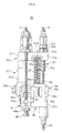
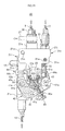
Fig. 2] Fig. 2 is a front view of a master cylinder unit of the brake device for a vehicle. - [
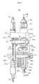
Fig. 3] Fig. 3 is a back view of the master cylinder unit of the brake device for a vehicle. - [
Fig. 4] Fig. 4 is a right side view with a part in cross section of the master cylinder unit of the brake device for a vehicle. - [
Fig. 5] Fig. 5 is a left side view with a part in cross section of the master cylinder unit of the brake device for a vehicle. - [
Fig. 6] Fig. 6 is a plan view of the master cylinder unit of the brake device for a vehicle. - [
Fig. 7] Fig. 7 is a bottom view of the master cylinder unit of the brake device for a vehicle. - [
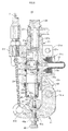
Fig. 8] Fig. 8 is a cross-sectional view taken along a line VIII-VIII inFig. 5 . - [
Fig. 9] Fig. 9 is a perspective view of a front side of the master cylinder unit showing an embodiment of the present invention. - [
Fig. 10] Fig. 10 is a perspective view of a back side of the hydraulic master cylinder unit. - [
Fig. 11] Fig. 11 is a back view with a part in cross section of the master cylinder unit in a state where only a first operation lever is operated so as to operate only a hydraulic brake. - [
Fig. 12] Fig. 12 is a front view of the master cylinder unit brought into an interlocking state by operating only a second operation lever. - [
Fig. 13] Fig. 13 is a front view of the master cylinder unit in a state where an operation of the hydraulic brake is restricted by operating only the second operation lever. - [
Fig. 14] Fig. 14 is a back view with a part in cross section of the master cylinder unit in a state where only the second operation lever is operated so as to restrict an operation of a hydraulic brake. - [
Fig. 15] Fig. 15 is a front view of the master cylinder unit when both operation levers are operated. - [
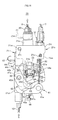
Fig. 16] Fig. 16 is a back view with a part in cross section of the master cylinder unit when both operation levers are operated. - [
Fig. 17] Fig. 17 is an exploded perspective view of the master cylinder unit. -
Fig. 1 to Fig. 17 show one embodiment of a brake device for a bar handle vehicle of the present invention. As shown inFig. 1 , abrake device 1 for a bar handle vehicle of this embodiment includes: afront wheel brake 2 and arear wheel brake 3; a front-wheel-brake-use operator 4 (first brake operator of the present invention) ; and a rear-wheel-brake-use operator 5 (second brake operator of the present invention). Amaster cylinder unit 20 is interposed between thefront wheel brake 2 and the front-wheel-brake-use operator 4 and between therear wheel brake 3 and the rear-wheel-brake-use operator 5. - In the explanation of the master cylinder unit made hereinafter, a left side and a right side are a left side and a right side as viewed in a front view from a driver's side as shown in
Fig. 1 . Accordingly, the explanation is made by assuming a front-wheel-brake-use operator 4 side as a right side and a rear-wheel-brake-use operator 5 side as a left side. Further, the description relating to a clockwise direction and a counterclockwise direction is also made by assuming these directions as directions as viewed in a front view in the same manner as described above. - As the
front wheel brake 2, a hydraulic disk brake is used where acaliper body 2b provided with a piston is combined with adisc rotor 2a which rotates integrally with a front wheel. As therear wheel brake 3, a mechanical drum brake is used where a pair ofbrake shoes back plate 3a in an expandable and opposedly facing manner, and bothbrake shoes anchor pin 3c as a fulcrum. - With respect to the front-wheel-brake-use operator 4, when the
operation lever 4a mounted on ahandle bar 6 is operated, afirst brake wire 7 is towed so that ahydraulic master cylinder 21 of themaster cylinder unit 20 is operated whereby a hydraulic pressure is supplied to thefront wheel brake 2 through ahydraulic pressure pipe 8 thus operating thefront wheel brake 2 singly. - With respect to the rear-wheel-brake-
use operator 5, when theoperation lever 5a mounted on thehandle bar 6 is operated, a second brake wire 9 (second brake connecting means of the present invention) is towed so that a rear-wheel-use brake wire 10 (mechanical-brake-side connecting means of the present invention) which operates therear wheel brake 3 is towed through themaster cylinder unit 20 whereby therear wheel brake 3 is operated. Towing of thesecond brake wire 9 also operates ahydraulic master cylinder 21 of themaster cylinder unit 20 so that a hydraulic pressure is supplied to thefront wheel brake 2 through thehydraulic pressure pipe 8 thus operating thefront wheel brake 2 in an interlocking manner with the operation of therear wheel brake 3. - The
master cylinder unit 20 is formed by combining thehydraulic master cylinder 21 which supplies a hydraulic pressure to thefront wheel brake 2 and alever mechanism 40. Thelever mechanism 40 includes a firstrotary lever 41, a secondrotary lever 42, aknocker 43 and anequalizer lever 44. - In the
hydraulic master cylinder 21, a bottomedcylinder hole 21b is formed in acylinder body 21a with an open lower end, and aunion boss portion 21c is formed on a bottom portion side of thecylinder hole 21b in a projecting manner. Aboss portion 21e provided with a fluid throughhole 21d which communicates with thecylinder hole 21b is formed on a right side of thecylinder body 21a in a projecting manner. Aconnector 12 connected to areservoir 11 by means of aseal member 12a is mounted on theboss portion 21e. As shown inFig. 8 , a plunger 22 (piston of the present invention) is slidably inserted into thecylinder hole 21b by means of afirst cup seal 23 and asecond cup seal 24. Thefirst cup seal 23 is fitted in afirst seal groove 23a formed on an inner peripheral surface of thecylinder hole 21b on a side closer to a cylinder hole bottom portion than the fluid throughhole 21d and adjacently to the fluid throughhole 21d. Thesecond cup seal 24 is fitted in asecond seal groove 24a formed on the inner peripheral surface of thecylinder hole 21b on a side closer to a cylinder hole opening than the fluid throughhole 21d and adjacently to the fluid throughhole 21d. Ahydraulic pressure chamber 25 is defined between a bottom portion of thecylinder hole 21b and thefirst cup seal 23. A replenishingchamber 21f which communicates with thefirst seal groove 23a, thesecond seal groove 24a and the fluid throughhole 21d is formed on the inner peripheral surface of thecylinder hole 21b between thefirst seal groove 23a and thesecond seal groove 24a. Aunion hole 21g which opens in a bottom portion of the cylinder hole is formed in theunion boss portion 21c. Thehydraulic pressure pipe 8 is connected to theunion boss portion 21c by means of abanjo bolt 26 and abanjo 27 mounted in theunion hole 21g. Thecylinder hole 21b and acaliper body 2b of thefront wheel brake 2 communicate with each other through thehydraulic pressure pipe 8. - The
plunger 22 is formed of a bottomed cylindrical shape having a recessedportion 22a which opens on a cylinder hole bottom portion side. In a peripheral wall of theplunger 22 on a recessed portion opening side, a plurality ofcommunication ports 22b having a small diameter which penetrate the peripheral wall so as to communicate the inside and the outside of the peripheral wall with each other and make thehydraulic pressure chamber 25 and the replenishingchamber 21f communicate with each other at an initial position in a non-operative state are formed in a circumferential direction. Between a bottom surface of the recessedportion 22a of theplunger 22 and a bottom surface of thecylinder hole 21b, areturn spring 28 which makes theplunger 22 in a non-operative state return to a preset predetermined initial position is disposed. In theplunger 22, a small-diameter shaft portion 22d is formed on asleeve portion 22c which slides in thecylinder hole 21b on a cylinder hole opening side. By bringing a steppedportion 22e formed between the small-diameter shaft portion 22d and thesleeve portion 22c into contact with acirclip 29 fitted on a large-diameter portion formed on a lower end side of thecylinder hole 21b, the initial position of theplunger 22 is set. Further, theplunger 22 is configured such that the small-diameter shaft portion 22d projects downward from a lower end opening of thecylinder body 21a, and adustproof boot 30 is mounted between a distal end portion of the small-diameter shaft portion 22d and an outer surface of thecirclip 29. - On an upper wall of the
cylinder body 21a, anupper bracket 21h having a rectangular shape as viewed in a plan view is formed in a projecting manner toward a front side and a left side of the upper wall. Theunion boss portion 21c is arranged on a back surface side and a right side of theupper bracket 21h. A firstwire guide portion 21i which guides thefirst brake wire 7 is arranged on a left side of theunion boss portion 21c. A secondwire guide portion 21j which guides thesecond brake wire 9 is arranged on a front side of theunion boss portion 21c. A stopperbolt mounting portion 21k on which astopper bolt 31 for restricting the rotation of the secondrotary lever 42 is mounted is arranged on a left side of the secondwire guide portion 21j. Vehiclebody mounting brackets upper bracket 21h in a projecting manner. Abolt hole 21n in which a vehicle body mounting bolt is mounted is formed in the vehiclebody mounting brackets upper bracket 21h disposed between the firstwire guide portion 21i and the stopperbolt mounting portion 21k, aspring mounting hole 21p in which adelay spring 32 is mounted is formed. - A pair of
lever holders cylinder body 21a on a front side and a back side in the vicinity of the cylinder hole opening portion. A throughhole 21s and a female threadedhole 21t in which a fixingpin 33 is mounted are coaxially formed in thelever holders wire guide portion 21u (guide portion of the present invention) is formed in a projecting manner on a lower end portion of thelever holder 21q on a front side. A second rotarylever contact surface 21v which sets an initial position of the secondrotary lever 42 by coming into contact with the secondrotary lever 42 is formed on a left side surface (a side surface on a cylinder body center axis side of the present invention) of the rear-wheel-use brakewire guide portion 21u. - The
stopper bolt 31 includes ashaft portion 31a provided with a male threaded portion, and ahead portion 31c having a large-diameter seat surface 31b. Thestopper bolt 31 is fixed using anut member 31d in a state where thestopper bolt 31 is threaded into a female threaded hole formed in a stopperbolt mounting portion 21k, and theshaft portion 31a projects downward from theupper bracket 21h by a predetermined length. - In the
lever mechanism 40, a bifurcated secondrotary base portion 42b which is formed on the secondrotary lever 42 is arranged between thelever holders rotary base portion 43a formed on theknocker 43 is arranged on a front side of an inner side of the secondrotary base portion 42b. A firstrotary base portion 41a formed on the firstrotary lever 41 is arranged on a back surface side of the secondrotary base portion 42b. The fixingpin 33 is inserted into and over thelever holders rotary base portion 41a, the secondrotary base portion 42b and the thirdrotary base portion 43a, and the fixingpin 33 is fixed using anut member 33a. Due to such a configuration, the firstrotary lever 41, the secondrotary lever 42 and theknocker 43 are rotatably connected to thelever holders lever holder 21q, anequalizer 44 is arranged above the rear-wheel-use brakewire guide portion 21u. Anequalizer connecting arm 42c formed on the secondrotary lever 42 and a second rotarylever connecting portion 44a formed on a left end portion of theequalizer lever 44 are rotatably and pivotally supported by means of a connectingpin 45 and aretainer ring 45a. - The first
rotary lever 41 is configured such that an adjustmentbolt mounting portion 41c extends downward to an opening portion of thecylinder hole 21b from the firstrotary base portion 41a provided with aninsertion hole 41b for the fixingpin 33, anadjustment bolt 46 which comes into contact with theknocker 43 is mounted on a female threadedportion 41d of the adjustmentbolt mounting portion 41c such that a projecting amount of theadjustment bolt 46 is adjustable using anut member 46a. A first brakewire connecting portion 41e to which an end portion of thefirst brake wire 7 is connected is formed on a back surface side of the adjustmentbolt mounting portion 41c. - The second
rotary lever 42 is formed into a block shape, and includes: the secondrotary base portion 42d formed in a bifurcated shape and having a frontside arm portion 42e and a backside arm portion 42f provided with aninsertion hole 42d for the fixingpin 33 respectively; a connectingarm 42g projecting toward a front surface direction and extending in a left direction from a lower portion of the frontside arm portion 42e; and anequalizer connecting arm 42c projecting upward from a left end portion of the connectingarm 42g. Aninsertion hole 42h for the connectingpin 45 is formed in theequalizer connecting arm 42c. A delayspring mounting portion 42i projecting in a back surface direction at a right angle is formed on an upper end portion of theequalizer connecting arm 42c in a projecting manner. Thespring mounting boss 42a projecting toward theupper bracket 21h is formed on an upper surface of the delayspring mounting portion 42i in a projecting manner. A knocker pushing and movingsurface 42j coming into contact with theknocker 43 and moving theknocker 43 by pushing is formed on a left lower portion of the backside arm portion 42f. Further, a guideportion contact surface 42k is formed on an outer surface of a right end of the connectingarm 42g. The guideportion contact surface 42k comes into contact with a second rotarylever contact surface 21v formed on the rear-wheel-use brakewire guide portion 21u so as to set an initial position of the secondrotary lever 42. - The
delay spring 32 is formed of a compression-type coil spring. An upper end side of thedelay spring 32 is mounted in thespring mounting hole 21p formed in theupper bracket 21h, and a lower end side of thedelay spring 32 is mounted on thespring mounting boss 42a of the secondrotary lever 42. - The
knocker 43 is configured such that a plunger pushing and movingportion 43c which is constantly brought into contact with a lower end portion of theplunger 22 is formed on a left side of the thirdrotary base portion 43a provided with aninsertion hole 43b for the fixingpin 33. Ahead portion 47a of apin member 47 embedded in theknocker 43 is arranged on a lower surface of the plunger pushing and movingportion 43c, and an outer end surface of thehead portion 47a forms an adjustmentbolt contact surface 47b which is brought into contact with theadjustment bolt 46. On a back surface side of the adjustmentbolt contact surface 47b, a receivingsurface 43d which is pushed and moved by the knocker pushing and movingsurface 42j formed on the secondrotary lever 42 is brought into contact with the knocker pushing and movingsurface 42j with a slight clearance therebetween. - The
equalizer lever 44 is arranged on a front side of thecylinder body 21a. A rear-wheel-use brakewire connecting portion 44b to which the rear-wheel-use brake wire 10 is connected is formed on one end portion of theequalizer lever 44. A second brakewire connecting portion 44c to which thesecond brake wire 9 is connected is formed on a center portion of theequalizer lever 44. The second rotarylever connecting portion 44a which is connected to theequalizer connecting arm 42c of the secondrotary lever 42 is formed on the other end portion of theequalizer lever 44. The second rotarylever connecting portion 44a is formed into a bifurcated shape where aninsertion hole 44d of the connectingpin 45 is formed in the bifurcated portions respectively. The second rotarylever connecting portion 44a is rotatably connected to theequalizer connecting arm 42c by inserting theequalizer connecting arm 42c between portions of the second rotarylever connecting portion 44a, by inserting the connectingpin 45 into theinsertion holes 44d, 44h and by mounting theretainer ring 45a on the connectingpin 45. - The above-mentioned first
rotary lever 41, secondrotary lever 42, andknocker 43 are respectively rotatably connected between thelever holders lever connecting portion 44a of theequalizer lever 44 is connected to theequalizer connecting arm 42c of the secondrotary lever 42 by means of the connectingpin 45. The rear-wheel-use brake wire 10 which is towed by means of the rear-wheel-use brakewire guide portion 21u is connected to the rear-wheel-use brakewire connecting portion 44b of theequalizer lever 44, and thesecond brake wire 9 which is towed by means of the secondwire guide portion 21j is connected to the second brakewire connecting portion 44c. Thefirst brake wire 7 which is towed by means of the firstwire guide portion 21i is connected to the first brakewire connecting portion 41e of the firstrotary lever 41. Thespring mounting boss 42a of the secondrotary lever 42 is arranged on a left side of a center axis CL2 of thespring mounting hole 21p formed in theupper bracket 21h which is an outer peripheral side of the cylinder body. One end of thedelay spring 32 is fitted into the inside of thespring mounting hole 21p, and the other end of thedelay spring 32 is inserted into thespring mounting boss 42a. With such a configuration, as viewed in a front view, thedelay spring 32 is arranged such that a lower end side of thedelay spring 32 is inclined leftwardly, that is, in an outer peripheral direction of the cylinder body, with respect to the center axis CL2 of thespring mounting hole 21p. - In the
master cylinder unit 20 formed as described above, in a non-operative state, as shown inFig. 1 to Fig. 10 , theplunger 22 of thehydraulic master cylinder 21 is brought into a state where theplunger 22 is biased in a direction toward the cylinder hole opening portion due to a repulsive force of thereturn spring 28, and an initial position of theplunger 22 is set by a contact between a steppedportion 22e of theplunger 22 and thecirclip 29. - An initial position of the first
rotary lever 41 is held by a tension of thefirst brake wire 7 connected to the first brakewire connecting portion 41e. An initial position of the secondrotary lever 42 is set in such a manner that a guideportion contact surface 42k is brought into contact with the second rotarylever contact surface 21v of the rear-wheel-use brakewire guide portion 21u due to a repulsive force of thedelay spring 32. The second rotarylever contact surface 21v and the guideportion contact surface 42k are arranged parallel to the cylinder center axis CL1. With respect to theknocker 43, the adjustmentbolt contact surface 47b is brought into contact with a distal end portion of theadjustment bolt 46, and the receivingsurface 43d is brought into contact with the knocker pushing and movingsurface 42j with a slight clearance therebetween, and the plunger pushing and movingportion 43c is brought into contact with theplunger 22. The receivingsurface 43d and the knocker pushing and movingsurface 42j are respectively arranged parallel to a radial direction line D1 which passes the center of the fixingpin 33 in a non-operative state. At the time of operating themaster cylinder unit 20, in an initial state where the receivingsurface 43d and the knocker pushing and movingsurface 42j are brought into contact with each other by eliminating the clearance, the contact surface between the receivingsurface 43d and the knocker pushing and movingsurface 42j is arranged on the radial direction line D1 which passes the center of fixingpin 33. With respect to theequalizer lever 44, in a state where the second rotarylever connecting portion 44a is connected to theequalizer connecting arm 42c, a tension of thesecond brake wire 9 and a tension of the rear-wheel-use brake wire 10 are balanced with each other so that theequalizer lever 44 is held in a horizontal state. As described previously, thedelay spring 32 is in a state where the lower end side of thedelay spring 32 is inclined leftward with respect to the center axis CL2 of thespring mounting hole 21p as viewed in a front view. - When the front-wheel-brake-use operator 4 is operated from a non-operative state, as shown in
Fig. 11 , thefirst brake wire 7 is towed, the first brakewire connecting portion 41e of the firstrotary lever 41 is towed upward, and the firstrotary lever 41 is rotated in a counterclockwise direction about the firstrotary base portion 41a. Along with the rotation of the firstrotary lever 41, theadjustment bolt 46 pushes and moves the adjustmentbolt contact surface 47b of theknocker 43 thus rotating theknocker 43 in a counterclockwise direction about the thirdrotary base portion 43a so that the plunger pushing and movingportion 43c moves theplunger 22 by pushing. With such an operation, a working fluid whose fluid pressure is increased applies a fluid pressure to thefront wheel brake 2 by means of thehydraulic pressure pipe 8 thus singly operating thefront wheel brake 2. - When the rear-wheel-brake-
use operator 5 is operated, firstly, as shown inFig. 12 , thesecond brake wire 9 is towed, and the whole equalizer lever is towed upward by means of the second brakewire connecting portion 44c of theequalizer lever 44. Along with the towing of theequalizer lever 44, the rear-wheel-use brake wire 10 connected to the rear-wheel-use brakewire connecting portion 44b is towed so that the operation of therear wheel brake 3 is started. At the same time, theequalizer connecting arm 42c of the secondrotary lever 42 which is connected to the second rotarylever connecting portion 44a of theequalizer lever 44 is also towed upward. The secondrotary lever 42 is rotated in a counterclockwise direction about the secondrotary base portion 42b against a repulsive force of thedelay spring 32. The knocker pushing and movingsurface 42j is brought into contact with the receivingsurface 43d of theknocker 43 and pushes and moves the receivingsurface 43d of theknocker 43 so that theplunger 22 is pushed and moved. Accordingly, a working fluid whose pressure is increased applies a fluid pressure to thefront wheel brake 2 by means of thehydraulic pressure pipe 8 thus operating thefront wheel brake 2 in an interlocking manner with the operation of therear wheel brake 3. - When the rear-wheel-brake-
use operator 5 is further operated, as shown inFig. 13 andFig. 14 , theequalizer lever 44 is further towed upward and, at the same time, the secondrotary lever 42 is rotated in the counterclockwise direction about the secondrotary base portion 42b, the delayspring mounting portion 42i is brought into contact with a distal end of a shaft portion of thestopper bolt 31 so that the rotation of the delayspring mounting portion 42i is restricted, and the rotation of theknocker 43 is stopped so that the applying of a fluid pressure to thefront wheel brake 2 is restricted. In such an operation, thedelay spring 32 is operated such that, along with the rotation of the secondrotary lever 42, a center line of thedelay spring 32 is temporarily arranged on the center axis CL2 of thespring mounting hole 21p and, thereafter, thedelay spring 32 is brought into a state where a lower end side of thedelay spring 32 is inclined rightward (toward the cylinder center axis CL1) with respect to the center axis CL2. - When the rear-wheel-brake-
use operator 5 is further strongly operated, the rear wheel brake is operated as follows. That is, the delayspring mounting portion 42i is brought into contact with the distal end of the shaft portion of thestopper bolt 31 so that the rotation of the secondrotary lever 42 is restricted whereby the position of the connectingpin 45 is fixed. Accordingly, theequalizer lever 44 is rotated in a clockwise direction about the connectingpin 45, and only the rear-wheel-use brake wire 10 is towed so that therear wheel brake 3 is operated further strongly. - As shown in
Fig. 15 andFig. 16 , when the front-wheel-brake-use operator 4 and the rear-wheel-brake-use operator 5 are simultaneously strongly operated, the firstrotary lever 41 is singly rotated by being towed by thefirst brake wire 7 thus strongly operating thefront wheel brake 2 by pushing and moving theplunger 22. At the same time, due to the movement of theequalizer lever 44 towed by thesecond brake wire 9, as described previously, the delayspring mounting portion 42i is brought into contact with the distal end of the shaft portion of thestopper bolt 3 so that the secondrotary lever 42 is brought into a state where the rotation of the secondrotary lever 42 is restricted and, thereafter, theequalizer lever 44 is rotated about the connectingpin 45 and tows the rear-wheel-use brake wire 10 thus strongly operating therear wheel brake 3. - In this embodiment, the rear-wheel-use brake
wire guide portion 21u is formed on a lower end portion of the frontside lever holder 21q in a proj ecting manner, the second rotarylever contact surface 21v which sets an initial position of the secondrotary lever 42 by coming into contact with the secondrotary lever 42 is formed on the left side surface of the rear-wheel-use brakewire guide portion 21u on a center axis side of the cylinder body. Accordingly, even when the secondrotary lever 42 is rotated about the fixingpin 33 at the time of operating the brake device, there is no possibility that a distal end side of the secondrotary lever 42 projects toward an outer peripheral side of thecylinder body 21a and hence, the miniaturization of themaster cylinder unit 20 can be realized. Further, there is no possibility that the distal end side of the secondrotary lever 42 projects toward the outer peripheral side of thecylinder body 21a and interferes with other parts at the time of operating the brake device and hence, the degree of freedom in layout of themaster cylinder unit 20 can be enhanced. Further, thelever holders cylinder body 21a, and the firstrotary lever 41, the secondrotary lever 42, theknocker 43, and the rear-wheel-use brakewire guide portion 21u can be arranged in a state where these parts are disposed close to the cylinder hole opening side and hence, the miniaturization of themaster cylinder unit 20 can be realized. Since the plunger-type hydraulic master cylinder is used as thehydraulic master cylinder 21, a length of thecylinder body 21a in the cylinder center axis CL1 direction can be decreased. Further, in this embodiment, thefirst seal groove 23a in which thefirst cup seal 23 is fitted and thesecond seal groove 24a in which thesecond cup seal 24 is fitted are formed close to the fluid throughhole 21d connected to thereservoir 11, and the replenishingchamber 21f which communicates with thefirst seal groove 23a, thesecond seal groove 24a and the fluid throughhole 21d is formed on the inner peripheral surface of thecylinder hole 21b and hence, a length of thecylinder body 21a in a cylinder center axis CL1 direction can be further decreased. - Here, the present invention is not limited to the above-mentioned embodiment, and there is no problem even when the hydraulic master cylinder is not a plunger-type hydraulic master cylinder. A mounting direction and a mounting position and the like of the master cylinder unit on a vehicle body are arbitrarily determined. There is also no problem even when the rear wheel brake is formed of a hydraulic brake and the front wheel brake is formed of a mechanical brake. Further, the second brake connecting means and the mechanical brake side connecting means of the present invention are not limited to the brake wire described in the above-mentioned embodiment.
-
- 1:
- brake device
- 2:
- front wheel brake
- 2a:
- disc rotor
- 2b:
- caliper body
- 3:
- rear wheel brake
- 3a:
- back plate
- 3b:
- brake shoe
- 3c:
- anchor pin
- 4:
- front-wheel-brake-use operator
- 4a:
- operation lever
- 5:
- rear-wheel-brake-use operator
- 5a:
- operation lever
- 6:
- handle bar
- 7:
- first brake wire
- 8:
- hydraulic pressure pipe
- 9:
- second brake wire
- 10:
- rear-wheel-use brake wire
- 11:
- reservoir
- 12:
- connector
- 12a:
- seal member
- 20:
- master cylinder unit
- 21:
- hydraulic master cylinder
- 21a:
- cylinder body
- 21b:
- cylinder hole
- 21c:
- union boss portion
- 21d:
- fluid through hole
- 21e:
- boss portion
- 21f:
- replenishing oil chamber
- 21g:
- union hole
- 21h:
- upper bracket
- 21i:
- first wire guide portion
- 21j:
- second wire guide portion
- 21k:
- stopper bolt mounting portion
- 21m:
- vehicle body mounting bracket
- 21n:
- bolt hole
- 21p:
- spring mounting hole
- 21q, 21r:
- lever holder
- 21s:
- through hole
- 21t:
- female threaded hole
- 21u:
- rear wheel brake wire guide portion
- 21v:
- second rotary lever contact surface
- 22:
- plunger
- 22a:
- recessed portion
- 22b:
- communication port
- 22c:
- sleeve portion
- 22d:
- small-diameter shaft portion
- 22e:
- stepped portion
- 23:
- first cup seal
- 23a:
- first seal groove
- 24:
- second cup seal
- 24a:
- second seal groove
- 25:
- hydraulic pressure chamber
- 26:
- banjo bolt
- 27:
- banjo
- 28:
- return spring
- 29:
- circlip
- 30:
- boot
- 31:
- stopper bolt
- 31a:
- shaft portion
- 31b:
- seat surface
- 31c:
- head portion
- 31d:
- nut member
- 32:
- delay spring
- 33:
- fixing pin
- 33a:
- nut member
- 40:
- lever mechanism
- 41:
- first rotary lever
- 41a:
- first rotary base portion
- 41b:
- insertion hole
- 41c:
- adjustment bolt mounting portion
- 41d:
- female threaded portion
- 41e:
- first brake wire connecting portion
- 42:
- second rotary lever
- 42a:
- spring mounting boss
- 42b:
- second rotary base portion
- 42c:
- equalizer connecting arm
- 42d:
- insertion hole
- 42e:
- front side arm portion
- 42f:
- back side arm portion
- 42g:
- connecting arm
- 42h:
- insertion hole
- 42i:
- delay spring mounting portion
- 42j:
- knocker pushing and moving surface
- 42k:
- guide portion contact surface
- 43:
- knocker
- 43a:
- third rotary base portion
- 43b:
- insertion hole
- 43c:
- plunger pushing and moving portion
- 43d:
- receiving surface
- 44:
- equalizer lever
- 44a:
- second rotary lever connecting portion
- 44b:
- rear-wheel-use brake wire connecting portion
- 44c:
- second brake wire connecting portion
- 44d:
- insertion hole
- 45:
- connecting pin
- 45a:
- retainer ring
- 46:
- adjustment bolt
- 46a:
- nut member
- 47:
- pin member
- 47a:
- head portion
- 47b:
- adjustment bolt contact surface
Claims (3)
- A brake device for a bar handle vehicle where either one of a front wheel brake and a rear wheel brake is formed of a hydraulic brake and the other brake is formed of a mechanical brake, the hydraulic brake is operated singly by operating a first brake operator by means of a master cylinder unit formed by combining a hydraulic master cylinder and a lever mechanism, the hydraulic brake and the mechanical brake are operated in an interlocking manner by operating a second brake operator by means of the master cylinder unit, the lever mechanism includes a first rotary lever, a second rotary lever, a knocker and an equalizer lever, a first brake connecting means connected to the first brake operator is connected to the first rotary lever, a piston of the hydraulic master cylinder is operated by operating the first brake operator by means of the knocker which the first rotary lever moves by pushing thus singly operating the hydraulic brake, a second brake connecting means connected to the second brake operator, a mechanical brake side connecting means connected to the mechanical brake and the second rotary lever are connected to the equalizer lever, the mechanical brake side connecting means is towed by operating the second brake operator by means of the equalizer lever thus operating the mechanical brake, and the equalizer lever rotates the second rotary lever so that the piston of the hydraulic master cylinder is operated by means of the knocker which the second rotary lever moves by pushing thus operating the hydraulic brake in an interlocking manner with the operation of the mechanical brake, wherein
a guide portion which guides the mechanical brake side connecting means toward the equalizer lever is mounted on a cylinder body of the hydraulic master cylinder in a projecting manner, a second rotary lever contact surface brought into contact with the second rotary lever is formed on a cylinder body center axis side of the guide portion, the second rotary lever is biased so as to rotate in a non-operating direction about a fixing pin which forms a rotational fulcrum due to a repulsive force of a delay spring disposed between the second rotary lever and the cylinder body, and a guide portion contact surface which sets an initial position of the second rotary lever by being brought into contact with the second rotary lever contact surface is formed on the second rotary lever. - The brake device for a bar handle vehicle according to claim 1, wherein a lever holder which rotatably and pivotally supports the first rotary lever, the second rotary lever and the knocker by means of the fixing pin is mounted on a cylinder hole opening side of the cylinder body in a projecting manner, and the guide portion is formed on a projecting side end portion of the lever holder.
- The brake device for a bar handle vehicle according to claim 1 or 2, wherein the hydraulic master cylinder is a plunger-type hydraulic master cylinder.
Applications Claiming Priority (2)
| Application Number | Priority Date | Filing Date | Title |
|---|---|---|---|
| JP2013177883A JP5860856B2 (en) | 2013-08-29 | 2013-08-29 | Bar handle vehicle brake system |
| PCT/JP2014/072360 WO2015030026A1 (en) | 2013-08-29 | 2014-08-27 | Brake device for vehicle that has handlebars |
Publications (3)
| Publication Number | Publication Date |
|---|---|
| EP3040260A1 true EP3040260A1 (en) | 2016-07-06 |
| EP3040260A4 EP3040260A4 (en) | 2017-05-17 |
| EP3040260B1 EP3040260B1 (en) | 2020-03-11 |
Family
ID=52586578
Family Applications (1)
| Application Number | Title | Priority Date | Filing Date |
|---|---|---|---|
| EP14839732.6A Active EP3040260B1 (en) | 2013-08-29 | 2014-08-27 | Brake device for vehicle that has handlebars |
Country Status (5)
| Country | Link |
|---|---|
| EP (1) | EP3040260B1 (en) |
| JP (1) | JP5860856B2 (en) |
| CN (1) | CN105452096B (en) |
| ES (1) | ES2797485T3 (en) |
| WO (1) | WO2015030026A1 (en) |
Cited By (1)
| Publication number | Priority date | Publication date | Assignee | Title |
|---|---|---|---|---|
| WO2019102375A1 (en) * | 2017-11-22 | 2019-05-31 | Piaggio & C. S.P.A. | Combined braking system for vehicles, especially for motorcycles |
Families Citing this family (4)
| Publication number | Priority date | Publication date | Assignee | Title |
|---|---|---|---|---|
| JP6606520B2 (en) * | 2017-02-17 | 2019-11-13 | 日信工業株式会社 | Brake hydraulic pressure control device for vehicles |
| WO2019235040A1 (en) * | 2018-06-07 | 2019-12-12 | 本田技研工業株式会社 | Interlocking brake device for straddle type vehicle |
| CN111731431A (en) * | 2019-03-25 | 2020-10-02 | 明鸿工业股份有限公司 | Brake linkage system |
| CN117509070B (en) * | 2024-01-05 | 2024-04-05 | 常州海图信息科技股份有限公司 | Mining belt conveyor with tearing detection function and mining belt conveyor method |
Family Cites Families (6)
| Publication number | Priority date | Publication date | Assignee | Title |
|---|---|---|---|---|
| JP3790025B2 (en) * | 1997-09-18 | 2006-06-28 | 株式会社日立製作所 | Brake device for motorcycle |
| JP4206181B2 (en) * | 1999-12-15 | 2009-01-07 | 本田技研工業株式会社 | Interlocking brake device |
| JP4532753B2 (en) * | 2001-01-24 | 2010-08-25 | 日信工業株式会社 | Bar handle vehicle brake system |
| CN2542548Y (en) * | 2002-04-03 | 2003-04-02 | 夏伟 | Double-coupled brake device of motorcycle |
| JP2009202650A (en) * | 2008-02-26 | 2009-09-10 | Honda Motor Co Ltd | Interlocking brake device for vehicle |
| CN201472594U (en) * | 2009-06-22 | 2010-05-19 | 徐盟贵 | Front and post brake link device of two-wheel vehicle |
-
2013
- 2013-08-29 JP JP2013177883A patent/JP5860856B2/en not_active Expired - Fee Related
-
2014
- 2014-08-27 CN CN201480044058.4A patent/CN105452096B/en active Active
- 2014-08-27 EP EP14839732.6A patent/EP3040260B1/en active Active
- 2014-08-27 ES ES14839732T patent/ES2797485T3/en active Active
- 2014-08-27 WO PCT/JP2014/072360 patent/WO2015030026A1/en not_active Ceased
Non-Patent Citations (1)
| Title |
|---|
| See references of WO2015030026A1 * |
Cited By (2)
| Publication number | Priority date | Publication date | Assignee | Title |
|---|---|---|---|---|
| WO2019102375A1 (en) * | 2017-11-22 | 2019-05-31 | Piaggio & C. S.P.A. | Combined braking system for vehicles, especially for motorcycles |
| TWI758564B (en) * | 2017-11-22 | 2022-03-21 | 義大利商比雅久股份有限公司 | Combined braking system for vehicles |
Also Published As
| Publication number | Publication date |
|---|---|
| CN105452096A (en) | 2016-03-30 |
| ES2797485T3 (en) | 2020-12-02 |
| WO2015030026A1 (en) | 2015-03-05 |
| EP3040260A4 (en) | 2017-05-17 |
| CN105452096B (en) | 2018-01-12 |
| JP5860856B2 (en) | 2016-02-16 |
| EP3040260B1 (en) | 2020-03-11 |
| JP2015044528A (en) | 2015-03-12 |
Similar Documents
| Publication | Publication Date | Title |
|---|---|---|
| EP3048035B1 (en) | Brake device for vehicle that has handlebars | |
| EP3040260B1 (en) | Brake device for vehicle that has handlebars | |
| JP6327978B2 (en) | Bar handle vehicle brake system | |
| CN107697213B (en) | Brake device for operating handle type vehicle | |
| CN105073572B (en) | Braking device for joystick type vehicles | |
| JP6346815B2 (en) | Bar handle vehicle brake system | |
| JP6042759B2 (en) | Bar handle vehicle brake system | |
| JP6510882B2 (en) | Bar handle brake system | |
| JP6316137B2 (en) | Bar handle vehicle brake system | |
| JP6202933B2 (en) | Bar handle vehicle brake system | |
| JP6400567B2 (en) | Bar handle vehicle brake system | |
| JP2016007970A (en) | Bar handle vehicle brake system | |
| JP4234237B2 (en) | Brake equipment for motorcycles | |
| US9200687B2 (en) | Mechanical type disc brake | |
| JP2015044530A (en) | Brake device for bar handle vehicle | |
| JP2014196019A (en) | Brake device for bar handle vehicle | |
| JP2005022533A (en) | Hydraulic master cylinder device for bar handle vehicle | |
| JPH10218067A (en) | Dual system disc brake system for bar handle vehicles | |
| JP2014189123A (en) | Brake device for lever handle vehicle | |
| JP6202934B2 (en) | Bar handle vehicle brake system | |
| JP2014189125A (en) | Brake device for lever handle vehicle | |
| JP2005280621A (en) | Bar handle vehicle control lever |
Legal Events
| Date | Code | Title | Description |
|---|---|---|---|
| PUAI | Public reference made under article 153(3) epc to a published international application that has entered the european phase |
Free format text: ORIGINAL CODE: 0009012 |
|
| 17P | Request for examination filed |
Effective date: 20160226 |
|
| AK | Designated contracting states |
Kind code of ref document: A1 Designated state(s): AL AT BE BG CH CY CZ DE DK EE ES FI FR GB GR HR HU IE IS IT LI LT LU LV MC MK MT NL NO PL PT RO RS SE SI SK SM TR |
|
| AX | Request for extension of the european patent |
Extension state: BA ME |
|
| DAX | Request for extension of the european patent (deleted) | ||
| A4 | Supplementary search report drawn up and despatched |
Effective date: 20170419 |
|
| RIC1 | Information provided on ipc code assigned before grant |
Ipc: B62L 3/08 20060101AFI20170411BHEP Ipc: B62L 3/02 20060101ALI20170411BHEP Ipc: B60T 11/04 20060101ALI20170411BHEP Ipc: B60T 7/10 20060101ALI20170411BHEP Ipc: B60T 11/18 20060101ALI20170411BHEP Ipc: B60T 11/10 20060101ALI20170411BHEP Ipc: B60T 8/26 20060101ALI20170411BHEP |
|
| GRAP | Despatch of communication of intention to grant a patent |
Free format text: ORIGINAL CODE: EPIDOSNIGR1 |
|
| STAA | Information on the status of an ep patent application or granted ep patent |
Free format text: STATUS: GRANT OF PATENT IS INTENDED |
|
| INTG | Intention to grant announced |
Effective date: 20191125 |
|
| GRAS | Grant fee paid |
Free format text: ORIGINAL CODE: EPIDOSNIGR3 |
|
| GRAA | (expected) grant |
Free format text: ORIGINAL CODE: 0009210 |
|
| STAA | Information on the status of an ep patent application or granted ep patent |
Free format text: STATUS: THE PATENT HAS BEEN GRANTED |
|
| RIN1 | Information on inventor provided before grant (corrected) |
Inventor name: UEHARA, KAZUMASA |
|
| RAP1 | Party data changed (applicant data changed or rights of an application transferred) |
Owner name: NISSIN KOGYO CO., LTD. |
|
| RIN1 | Information on inventor provided before grant (corrected) |
Inventor name: UEHARA, KAZUMASA |
|
| AK | Designated contracting states |
Kind code of ref document: B1 Designated state(s): AL AT BE BG CH CY CZ DE DK EE ES FI FR GB GR HR HU IE IS IT LI LT LU LV MC MK MT NL NO PL PT RO RS SE SI SK SM TR |
|
| REG | Reference to a national code |
Ref country code: GB Ref legal event code: FG4D |
|
| REG | Reference to a national code |
Ref country code: CH Ref legal event code: EP |
|
| REG | Reference to a national code |
Ref country code: AT Ref legal event code: REF Ref document number: 1242828 Country of ref document: AT Kind code of ref document: T Effective date: 20200315 |
|
| REG | Reference to a national code |
Ref country code: DE Ref legal event code: R096 Ref document number: 602014062296 Country of ref document: DE |
|
| REG | Reference to a national code |
Ref country code: IE Ref legal event code: FG4D |
|
| PG25 | Lapsed in a contracting state [announced via postgrant information from national office to epo] |
Ref country code: NO Free format text: LAPSE BECAUSE OF FAILURE TO SUBMIT A TRANSLATION OF THE DESCRIPTION OR TO PAY THE FEE WITHIN THE PRESCRIBED TIME-LIMIT Effective date: 20200611 Ref country code: FI Free format text: LAPSE BECAUSE OF FAILURE TO SUBMIT A TRANSLATION OF THE DESCRIPTION OR TO PAY THE FEE WITHIN THE PRESCRIBED TIME-LIMIT Effective date: 20200311 Ref country code: RS Free format text: LAPSE BECAUSE OF FAILURE TO SUBMIT A TRANSLATION OF THE DESCRIPTION OR TO PAY THE FEE WITHIN THE PRESCRIBED TIME-LIMIT Effective date: 20200311 |
|
| REG | Reference to a national code |
Ref country code: NL Ref legal event code: MP Effective date: 20200311 |
|
| PG25 | Lapsed in a contracting state [announced via postgrant information from national office to epo] |
Ref country code: GR Free format text: LAPSE BECAUSE OF FAILURE TO SUBMIT A TRANSLATION OF THE DESCRIPTION OR TO PAY THE FEE WITHIN THE PRESCRIBED TIME-LIMIT Effective date: 20200612 Ref country code: BG Free format text: LAPSE BECAUSE OF FAILURE TO SUBMIT A TRANSLATION OF THE DESCRIPTION OR TO PAY THE FEE WITHIN THE PRESCRIBED TIME-LIMIT Effective date: 20200611 Ref country code: LV Free format text: LAPSE BECAUSE OF FAILURE TO SUBMIT A TRANSLATION OF THE DESCRIPTION OR TO PAY THE FEE WITHIN THE PRESCRIBED TIME-LIMIT Effective date: 20200311 Ref country code: SE Free format text: LAPSE BECAUSE OF FAILURE TO SUBMIT A TRANSLATION OF THE DESCRIPTION OR TO PAY THE FEE WITHIN THE PRESCRIBED TIME-LIMIT Effective date: 20200311 Ref country code: HR Free format text: LAPSE BECAUSE OF FAILURE TO SUBMIT A TRANSLATION OF THE DESCRIPTION OR TO PAY THE FEE WITHIN THE PRESCRIBED TIME-LIMIT Effective date: 20200311 |
|
| REG | Reference to a national code |
Ref country code: LT Ref legal event code: MG4D |
|
| PG25 | Lapsed in a contracting state [announced via postgrant information from national office to epo] |
Ref country code: NL Free format text: LAPSE BECAUSE OF FAILURE TO SUBMIT A TRANSLATION OF THE DESCRIPTION OR TO PAY THE FEE WITHIN THE PRESCRIBED TIME-LIMIT Effective date: 20200311 |
|
| PG25 | Lapsed in a contracting state [announced via postgrant information from national office to epo] |
Ref country code: PT Free format text: LAPSE BECAUSE OF FAILURE TO SUBMIT A TRANSLATION OF THE DESCRIPTION OR TO PAY THE FEE WITHIN THE PRESCRIBED TIME-LIMIT Effective date: 20200805 Ref country code: IS Free format text: LAPSE BECAUSE OF FAILURE TO SUBMIT A TRANSLATION OF THE DESCRIPTION OR TO PAY THE FEE WITHIN THE PRESCRIBED TIME-LIMIT Effective date: 20200711 Ref country code: SK Free format text: LAPSE BECAUSE OF FAILURE TO SUBMIT A TRANSLATION OF THE DESCRIPTION OR TO PAY THE FEE WITHIN THE PRESCRIBED TIME-LIMIT Effective date: 20200311 Ref country code: SM Free format text: LAPSE BECAUSE OF FAILURE TO SUBMIT A TRANSLATION OF THE DESCRIPTION OR TO PAY THE FEE WITHIN THE PRESCRIBED TIME-LIMIT Effective date: 20200311 Ref country code: EE Free format text: LAPSE BECAUSE OF FAILURE TO SUBMIT A TRANSLATION OF THE DESCRIPTION OR TO PAY THE FEE WITHIN THE PRESCRIBED TIME-LIMIT Effective date: 20200311 Ref country code: LT Free format text: LAPSE BECAUSE OF FAILURE TO SUBMIT A TRANSLATION OF THE DESCRIPTION OR TO PAY THE FEE WITHIN THE PRESCRIBED TIME-LIMIT Effective date: 20200311 Ref country code: CZ Free format text: LAPSE BECAUSE OF FAILURE TO SUBMIT A TRANSLATION OF THE DESCRIPTION OR TO PAY THE FEE WITHIN THE PRESCRIBED TIME-LIMIT Effective date: 20200311 Ref country code: RO Free format text: LAPSE BECAUSE OF FAILURE TO SUBMIT A TRANSLATION OF THE DESCRIPTION OR TO PAY THE FEE WITHIN THE PRESCRIBED TIME-LIMIT Effective date: 20200311 |
|
| REG | Reference to a national code |
Ref country code: AT Ref legal event code: MK05 Ref document number: 1242828 Country of ref document: AT Kind code of ref document: T Effective date: 20200311 |
|
| REG | Reference to a national code |
Ref country code: ES Ref legal event code: FG2A Ref document number: 2797485 Country of ref document: ES Kind code of ref document: T3 Effective date: 20201202 |
|
| REG | Reference to a national code |
Ref country code: DE Ref legal event code: R097 Ref document number: 602014062296 Country of ref document: DE |
|
| PLBE | No opposition filed within time limit |
Free format text: ORIGINAL CODE: 0009261 |
|
| STAA | Information on the status of an ep patent application or granted ep patent |
Free format text: STATUS: NO OPPOSITION FILED WITHIN TIME LIMIT |
|
| PG25 | Lapsed in a contracting state [announced via postgrant information from national office to epo] |
Ref country code: DK Free format text: LAPSE BECAUSE OF FAILURE TO SUBMIT A TRANSLATION OF THE DESCRIPTION OR TO PAY THE FEE WITHIN THE PRESCRIBED TIME-LIMIT Effective date: 20200311 Ref country code: AT Free format text: LAPSE BECAUSE OF FAILURE TO SUBMIT A TRANSLATION OF THE DESCRIPTION OR TO PAY THE FEE WITHIN THE PRESCRIBED TIME-LIMIT Effective date: 20200311 |
|
| 26N | No opposition filed |
Effective date: 20201214 |
|
| PG25 | Lapsed in a contracting state [announced via postgrant information from national office to epo] |
Ref country code: SI Free format text: LAPSE BECAUSE OF FAILURE TO SUBMIT A TRANSLATION OF THE DESCRIPTION OR TO PAY THE FEE WITHIN THE PRESCRIBED TIME-LIMIT Effective date: 20200311 Ref country code: PL Free format text: LAPSE BECAUSE OF FAILURE TO SUBMIT A TRANSLATION OF THE DESCRIPTION OR TO PAY THE FEE WITHIN THE PRESCRIBED TIME-LIMIT Effective date: 20200311 |
|
| PG25 | Lapsed in a contracting state [announced via postgrant information from national office to epo] |
Ref country code: MC Free format text: LAPSE BECAUSE OF FAILURE TO SUBMIT A TRANSLATION OF THE DESCRIPTION OR TO PAY THE FEE WITHIN THE PRESCRIBED TIME-LIMIT Effective date: 20200311 |
|
| REG | Reference to a national code |
Ref country code: CH Ref legal event code: PL |
|
| PG25 | Lapsed in a contracting state [announced via postgrant information from national office to epo] |
Ref country code: CH Free format text: LAPSE BECAUSE OF NON-PAYMENT OF DUE FEES Effective date: 20200831 Ref country code: LU Free format text: LAPSE BECAUSE OF NON-PAYMENT OF DUE FEES Effective date: 20200827 Ref country code: LI Free format text: LAPSE BECAUSE OF NON-PAYMENT OF DUE FEES Effective date: 20200831 |
|
| REG | Reference to a national code |
Ref country code: BE Ref legal event code: MM Effective date: 20200831 |
|
| PG25 | Lapsed in a contracting state [announced via postgrant information from national office to epo] |
Ref country code: FR Free format text: LAPSE BECAUSE OF NON-PAYMENT OF DUE FEES Effective date: 20200831 |
|
| PG25 | Lapsed in a contracting state [announced via postgrant information from national office to epo] |
Ref country code: IE Free format text: LAPSE BECAUSE OF NON-PAYMENT OF DUE FEES Effective date: 20200827 Ref country code: BE Free format text: LAPSE BECAUSE OF NON-PAYMENT OF DUE FEES Effective date: 20200831 |
|
| REG | Reference to a national code |
Ref country code: DE Ref legal event code: R081 Ref document number: 602014062296 Country of ref document: DE Owner name: HITACHI ASTEMO, LTD., HITACHINAKA-SHI, JP Free format text: FORMER OWNER: NISSIN KOGYO CO., LTD., TOMI-CITY, NAGANO, JP |
|
| REG | Reference to a national code |
Ref country code: GB Ref legal event code: 732E Free format text: REGISTERED BETWEEN 20211210 AND 20211215 |
|
| REG | Reference to a national code |
Ref country code: ES Ref legal event code: PC2A Owner name: HITACHI ASTEMO, LTD. Effective date: 20220512 |
|
| PG25 | Lapsed in a contracting state [announced via postgrant information from national office to epo] |
Ref country code: TR Free format text: LAPSE BECAUSE OF FAILURE TO SUBMIT A TRANSLATION OF THE DESCRIPTION OR TO PAY THE FEE WITHIN THE PRESCRIBED TIME-LIMIT Effective date: 20200311 Ref country code: MT Free format text: LAPSE BECAUSE OF FAILURE TO SUBMIT A TRANSLATION OF THE DESCRIPTION OR TO PAY THE FEE WITHIN THE PRESCRIBED TIME-LIMIT Effective date: 20200311 Ref country code: CY Free format text: LAPSE BECAUSE OF FAILURE TO SUBMIT A TRANSLATION OF THE DESCRIPTION OR TO PAY THE FEE WITHIN THE PRESCRIBED TIME-LIMIT Effective date: 20200311 |
|
| PG25 | Lapsed in a contracting state [announced via postgrant information from national office to epo] |
Ref country code: MK Free format text: LAPSE BECAUSE OF FAILURE TO SUBMIT A TRANSLATION OF THE DESCRIPTION OR TO PAY THE FEE WITHIN THE PRESCRIBED TIME-LIMIT Effective date: 20200311 Ref country code: AL Free format text: LAPSE BECAUSE OF FAILURE TO SUBMIT A TRANSLATION OF THE DESCRIPTION OR TO PAY THE FEE WITHIN THE PRESCRIBED TIME-LIMIT Effective date: 20200311 |
|
| PGFP | Annual fee paid to national office [announced via postgrant information from national office to epo] |
Ref country code: DE Payment date: 20240702 Year of fee payment: 11 |
|
| PGFP | Annual fee paid to national office [announced via postgrant information from national office to epo] |
Ref country code: GB Payment date: 20240701 Year of fee payment: 11 |
|
| PGFP | Annual fee paid to national office [announced via postgrant information from national office to epo] |
Ref country code: ES Payment date: 20240902 Year of fee payment: 11 |
|
| PGFP | Annual fee paid to national office [announced via postgrant information from national office to epo] |
Ref country code: IT Payment date: 20240710 Year of fee payment: 11 |
|
| REG | Reference to a national code |
Ref country code: DE Ref legal event code: R119 Ref document number: 602014062296 Country of ref document: DE |
|
| GBPC | Gb: european patent ceased through non-payment of renewal fee |
Effective date: 20250827 |