EP3713050B1 - Induktionsmotor - Google Patents
Induktionsmotor Download PDFInfo
- Publication number
- EP3713050B1 EP3713050B1 EP19164551.4A EP19164551A EP3713050B1 EP 3713050 B1 EP3713050 B1 EP 3713050B1 EP 19164551 A EP19164551 A EP 19164551A EP 3713050 B1 EP3713050 B1 EP 3713050B1
- Authority
- EP
- European Patent Office
- Prior art keywords
- rotor
- resistivity
- conducting element
- axis
- copper
- Prior art date
- Legal status (The legal status is an assumption and is not a legal conclusion. Google has not performed a legal analysis and makes no representation as to the accuracy of the status listed.)
- Active
Links
- 230000006698 induction Effects 0.000 title claims description 25
- 230000003247 decreasing effect Effects 0.000 claims description 21
- 239000000463 material Substances 0.000 claims description 21
- RYGMFSIKBFXOCR-UHFFFAOYSA-N Copper Chemical compound [Cu] RYGMFSIKBFXOCR-UHFFFAOYSA-N 0.000 claims description 17
- 229910052802 copper Inorganic materials 0.000 claims description 16
- 239000010949 copper Substances 0.000 claims description 16
- 241000555745 Sciuridae Species 0.000 claims description 12
- 239000007787 solid Substances 0.000 claims description 11
- 239000011701 zinc Substances 0.000 claims description 11
- HCHKCACWOHOZIP-UHFFFAOYSA-N Zinc Chemical compound [Zn] HCHKCACWOHOZIP-UHFFFAOYSA-N 0.000 claims description 10
- 238000004519 manufacturing process Methods 0.000 claims description 10
- 230000007423 decrease Effects 0.000 claims description 9
- 229910000881 Cu alloy Inorganic materials 0.000 claims description 6
- 229910001297 Zn alloy Inorganic materials 0.000 claims description 6
- 239000000654 additive Substances 0.000 claims description 6
- 230000000996 additive effect Effects 0.000 claims description 6
- 229910045601 alloy Inorganic materials 0.000 claims description 5
- 239000000956 alloy Substances 0.000 claims description 5
- 229910052725 zinc Inorganic materials 0.000 claims description 5
- 239000004411 aluminium Substances 0.000 description 11
- 229910052782 aluminium Inorganic materials 0.000 description 11
- XAGFODPZIPBFFR-UHFFFAOYSA-N aluminium Chemical compound [Al] XAGFODPZIPBFFR-UHFFFAOYSA-N 0.000 description 11
- 230000005291 magnetic effect Effects 0.000 description 9
- 230000001360 synchronised effect Effects 0.000 description 9
- 239000004020 conductor Substances 0.000 description 7
- XEEYBQQBJWHFJM-UHFFFAOYSA-N Iron Chemical compound [Fe] XEEYBQQBJWHFJM-UHFFFAOYSA-N 0.000 description 6
- 230000007613 environmental effect Effects 0.000 description 4
- 238000000034 method Methods 0.000 description 4
- 229910000576 Laminated steel Inorganic materials 0.000 description 3
- 230000015556 catabolic process Effects 0.000 description 3
- -1 e.g. Substances 0.000 description 3
- 229910052742 iron Inorganic materials 0.000 description 3
- 229910000842 Zamak Inorganic materials 0.000 description 2
- 238000000429 assembly Methods 0.000 description 2
- 230000000712 assembly Effects 0.000 description 2
- 230000002500 effect on skin Effects 0.000 description 2
- 229910052751 metal Inorganic materials 0.000 description 2
- 239000002184 metal Substances 0.000 description 2
- 238000004804 winding Methods 0.000 description 2
- 229910000831 Steel Inorganic materials 0.000 description 1
- 238000001816 cooling Methods 0.000 description 1
- 230000001419 dependent effect Effects 0.000 description 1
- 238000009826 distribution Methods 0.000 description 1
- 230000000694 effects Effects 0.000 description 1
- 238000005516 engineering process Methods 0.000 description 1
- 230000002349 favourable effect Effects 0.000 description 1
- 239000003302 ferromagnetic material Substances 0.000 description 1
- 238000003475 lamination Methods 0.000 description 1
- 239000012768 molten material Substances 0.000 description 1
- 239000000843 powder Substances 0.000 description 1
- 239000010959 steel Substances 0.000 description 1
- 230000007704 transition Effects 0.000 description 1
Images


Classifications
-
- H—ELECTRICITY
- H02—GENERATION; CONVERSION OR DISTRIBUTION OF ELECTRIC POWER
- H02K—DYNAMO-ELECTRIC MACHINES
- H02K3/00—Details of windings
- H02K3/02—Windings characterised by the conductor material
-
- H—ELECTRICITY
- H02—GENERATION; CONVERSION OR DISTRIBUTION OF ELECTRIC POWER
- H02K—DYNAMO-ELECTRIC MACHINES
- H02K17/00—Asynchronous induction motors; Asynchronous induction generators
- H02K17/02—Asynchronous induction motors
- H02K17/16—Asynchronous induction motors having rotors with internally short-circuited windings, e.g. cage rotors
- H02K17/20—Asynchronous induction motors having rotors with internally short-circuited windings, e.g. cage rotors having deep-bar rotors
-
- H—ELECTRICITY
- H02—GENERATION; CONVERSION OR DISTRIBUTION OF ELECTRIC POWER
- H02K—DYNAMO-ELECTRIC MACHINES
- H02K19/00—Synchronous motors or generators
- H02K19/02—Synchronous motors
- H02K19/10—Synchronous motors for multi-phase current
-
- H—ELECTRICITY
- H02—GENERATION; CONVERSION OR DISTRIBUTION OF ELECTRIC POWER
- H02K—DYNAMO-ELECTRIC MACHINES
- H02K19/00—Synchronous motors or generators
- H02K19/02—Synchronous motors
- H02K19/14—Synchronous motors having additional short-circuited windings for starting as asynchronous motors
Definitions
- the present disclosure relates to electric motors of the types solid salient pole synchronous motors and squirrel cage induction motors.
- the present disclosure also relates to a method for producing such electric motors.
- a squirrel cage induction motor comprises a stator carrying a three-phase winding and a rotor with a squirrel cage comprising either die-cast or machined short-circuited rotor bars.
- die-cast rotor bars is more common in low power, small machine applications while machined bars are more common in high power, large machine applications. The reason for this is mainly the difficulty to die cast long rotor bars due to the cooling of the molten material.
- the rotor bars are most often made of copper or aluminium. By changing the material of the rotor bars, the induction motor obtains different starting characteristics.
- a low resistivity material such as, e.g., copper will have a break-down torque occurring at a higher rotor speed than a high resistivity material, such as, e.g., aluminium.
- the starting torque is higher for a high resistivity material, such as, e.g., aluminium, than for a material with lower resistivity, such as, e.g., copper.
- a high resistivity material such as, e.g., aluminium
- a material with lower resistivity such as, e.g., copper.
- Copper rotor induction motors will have higher efficiency than aluminium rotor induction motors.
- US 2014/0091668 A1 describes hybrid rotor bar assemblies, electric motors including hybrid rotor bar assemblies and methods of assembling the same.
- the hybrid rotor bar assembly includes a copper rotor bar, and an aluminium shims lining the rotor bars.
- the aluminium shim has the effect of tightening the copper rotor bars in the squirrel cage so as not to shave or abrade the soft copper rotors as they expand or shrink.
- the aluminium shims also functions as a secondary rotor bar which improves the starting torque of the electric motor.
- DE 10 2013 016654 A1 discloses a squirrel-cage induction motor, which has a rotor constructed of laminated steel sheets with a plurality of slots. A copper wire extending in a lamination direction is arranged in the slots, and a gap-filling conductor is poured into the slot.
- a dynamo-electric machine which comprises a rotor that is rotatable within a stator provided with stator windings.
- the rotor has an annular core of ferromagnetic material provided with external circumferential layers, and the layers comprise an environmental enclosure and at least one sleeve of electrically conductive material disposed between the rotor core and the environmental enclosure.
- the environmental enclosure is made from an electrically conductive material and the electrical resistance of the environmental enclosure is higher than that of the or each sleeve.
- US 1 777 320 A discloses a rotor with radial slits, wherein an axially oriented coarse copper wire is fitted at the bottom of each slit before pouring Zamak, an alloy with 93% zinc. This produces a heterogenous copper-Zamak body in each slit.
- EP 3 373 424 A1 relates to a method for producing a rotor of an electric machine by additive manufacturing.
- the rotor is preferably designed as a squirrel-cage rotor.
- the end rings and/or squirrel-cage bars are produced by means of a metal powder application method.
- JP S16 116952 A discloses a rotor for an electrical machine, where homogeneous rotor bars of 65% Cu and 35% Zn are inserted into a rotor core of iron in a direction parallel with the rotation axis.
- An object of the present invention is to provide a rotor for an electric induction machine and/or a synchronous machine of the solid salient pole type, which rotor at least alleviates one of the problems with the prior art.
- Another object of the present invention is to provide a rotor for a squirrel cage induction motor and/or a synchronous machine of the solid salient pole type, which rotor enables an electric induction motor and/or a synchronous machine of the solid salient pole type which has high efficiency and good starting torque characteristics when operated as a motor, compared to electric machines according to the prior art.
- At least one of these objects is provided with a rotor according to the independent claim.
- a rotor according to claim 1 According to a first aspect of the present invention, there is provided a rotor according to claim 1.
- a current is induced in the conducting elements and a torque is produced on the rotor.
- the part of the conducting element at the largest distance from the rotor axis will determine the starting characteristics at high slips as the current distribution is determined by the skin effect. As the rotor speed increases, the current in the conducting element will successively progress deeper into the conducting element due to the skin effect.
- the resistivity in the conducting element may decrease continuously with a decreasing distance from the rotor axis.
- the resistivity in the conducting element may decrease in steps with a decreasing distance from the rotor axis.
- a conducting element in which the resistivity decreases in steps may be easier to manufacture than a conducting element with continuously decreasing resistivity.
- the resistivity of the conducting element may be constant at a specific distance from the rotor axis, i.e., the resistivity profile perpendicular to the length axis of the conducting element is the same along the entire conducting element.
- the rotor may be of the solid salient pole type. This type of rotor has conducting elements of solid metal such as, e.g., pole shoes.
- the rotor may be for a squirrel cage induction motor and the conducting element a rotor bar.
- a squirrel cage induction motor usually comprises a number of rotor bars which are inserted in slots in the rotor cage, which consists of laminated steel plates.
- the rotor bar may comprise at least a first layer constituted of a material with a first resistivity, and a second layer constituted of a material with a second resistivity which is lower than the first resistivity, wherein the second layer is arranged closer to the rotor axis than the first layer.
- the first layer may consist an alloy of copper and zinc, and the second layer may consist of copper. This combination of materials gives the desired difference in
- the rotor bar may have a continuously decreasing resistivity with a decreasing distance from the rotor axis. By having a continuously decreasing resistivity the characteristics of the electric induction motor may be optimized.
- the rotor bar consists of by an alloy of copper and zinc, wherein the ratio of zinc in the alloy decreases with a decreasing distance to the rotor axis. This is a favourable embodiment of the rotor bar.
- the rotor bar may be manufactured by additive manufacturing. This gives a large degree of freedom in how the resistivity varies in the rotor bar.
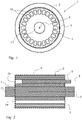
- FIG. 1 shows schematically an electric induction motor 1 of the type squirrel cage induction motor with a rotor according to an embodiment of the invention.
- the motor 1 comprises a stator 2, and a rotor 3 with a rotor axis 4, arranged with an air gap 5 between the rotor 3 and the stator 2.
- the rotor 3 comprises conducting material, and during operation of the motor 1, the stator 2 is arranged to provide a main magnetic field, which produces a torque on the rotor 3 in relation to the stator 2.
- the rotor 3 comprises a rotor shaft 13 through which the rotor axis 4 extends.
- the rotor comprises a large number of slots 10 in which rotor bars are arranged.
- Figure 2 shows schematically the electric induction motor 1 of Fig. 1 in a longitudinal cross sectional view. Two of the slots 10 are shown.
- the conducting material in the rotor 3 comprises a number of conducting elements of solid conducting material in the form of rotor bars 6, of which only one is shown in Fig. 2 .
- the rotor bar 6 is shown partially inserted in the corresponding slot 6.
- the resistivity within each rotor bar 6 decreases with a decreasing distance from the rotor axis 4.
- the rotor bar 6 comprises a length axis 8 and extends with its length axis 8 essentially parallel to the rotor axis 4 along at least half of the main magnetic field provided by the stator 2 during operation.
- the rotor bar 6 extends along the entire iron in the rotor.
- the main magnetic field of the stator 2 is constrained by the iron in the stator 2 and the rotor 3 as indicated by the boundary 9.
- the main magnetic field of the stator 2 is indicated with the dotted line 9.
- the rotor 3 comprises laminated steel sheets in which slots 10 are formed.
- the rotor bars 6 are arranged in the slots 10.
- the rotor bars 6 may be manufactured by additive manufacturing (AM). With the present technology it is possible to 3D-print a rotor bar 6 consisting of several materials or even mixing materials to have a continuous transition between different materials throughout the height perpendicular to the length axis 8 of the rotor bar 6. In this way, the starting characteristics of the motor 1 may be optimized throughout the starting operation of the motor 1 with a smaller impact on efficiency compared to the single material rotor bar design according to the prior art. This is due to the low resistivity in the parts of the rotor bar 6 being closer to the rotor axis 4. In theory, the rotor bar 6 can be designed such that the motor 1 can ride on the break-down torque throughout the entire starting operation. This would result in extremely high torque per current performance.
- AM additive manufacturing
- the skin depth of the rotor bars 6 will increase and the current in the rotor bars 6 will penetrate deeper and deeper into the rotor bars 6 as the motor 1 accelerates. It is therefore desirable to have a high resistivity in the parts of the rotor bars 6 at the largest distance from the rotor axis 4, for starting purposes and to have lower resistivity in the parts of the rotor bars 6 closer to the rotor axis 4 for steady-state operation.
- a rotor bar 6 having a varying resistivity along it height perpendicular to the length axis 8 will provide good starting characteristics of the motor while maintaining a high efficiency at steady-state operation.
- This kind of multi-material rotor bar 6 design can be manufactured by additive manufacturing or by other means.
- Figures 3a-3c show three different embodiments of a rotor bar 6.
- the rotor bar shown in Fig. 3a has two layers 11' and 11".
- the uppermost layer 11' in Fig. 3a is to be arranged at the largest distance from the rotor axis 4 and has a higher resistivity than the lowermost layer 11".
- the uppermost layer 11' may consist of an alloy of copper and zinc while the innermost layer may be made of pure copper.
- a suitable alloy for the layer at the largest distance from the rotor axis 4 is an alloy sold under the name CuZn37.
- the rotor bar 6 shown in Fig. 3b has a continuously decreasing resistivity with a decreasing distance from the rotor axis.
- the rotor bars 6 in figures 3a-3c are illustrated with rectangular shapes. However, the rotor bars 6 may have any shapes. The shape of the layers does not have to be rectangular and the thickness of the layers 11 does not have to be constant.
- the material in the different layers 11 consists of an alloy of copper and zinc with a decreasing ratio of zinc in the layers towards the rotor axis 4.
- the layer closest to the rotor axis 4 may be of essentially pure copper.
- the rotor bars shown in Fig. 3a-3c are preferably manufactured using an additive manufacturing technique. This is especially important for the embodiments shown in Fig. 3b and 3c , which would be particularly difficult to manufacture with other methods.
- Fig. 4 shows in an axial view a motor 1 in the form of a solid salient pole synchronous motor with a rotor according to another embodiment of the invention.
- the motor 1 comprises a stator 2, and a rotor 3 with a rotor axis 4, arranged with an air gap 5 between the rotor 3 and the stator 2.
- the rotor 3 comprises conducting material, and during operation of the motor 1, the stator 2 is arranged to provide a main magnetic field, which produces a torque on the rotor 3 in relation to the stator 2.
- the rotor 3 comprises conducting elements in the form of pole shoes 12.
- the pole shoes 12 comprises a varying resistivity with a decreasing resistivity with an decreasing distance from the rotor axis 4.
- Pole shoes in a solid salient pole synchronous machine are, due to strength considerations and magnetic properties, usually made from steel.
- Figure 5 shows a comparison of starting characteristic between rotor bars 6, shown in Fig. 3 , of different materials.
- Curve 21 shows the current on the left axis as a function of the rotational speed of the induced magnetic field in the rotor 3 for rotor bars 6 of copper.
- Curve 22 shows the current for rotor bars 6 of aluminium, while curve 23 shows the current for rotor bars 6 of CuZn37.
- Curve 31 shows the torque on the right axis as a function of the speed of the magnetic field in the rotor 3 for rotor bars of copper.
- Curve 32 shows the torque for rotor bars 6 of aluminium, while curve 33 shows the torque for rotor bars 6 of CuZn37.
- the scale on the left side is in kiloamperes (kA).
- the scale on the right side is in kilonewton meters (kNm).
- the speed on the x-axis shows rotational speed of the rotor in revolutions per minute (rpm).
- the rotational speed is 1500 rpm when the rotor runs at synchronous speed.
- the rotational speed is zero when the rotor is at standstill. It can be clearly seen in Fig. 5 that the torque at 1500 rpm, for CuZn37 is highest followed by aluminium and copper. Also, it is shown that the current at zero speed, is highest for copper followed by aluminium and CuZn37.
- a high speed for the breakdown torque is equivalent to low rotor resistive losses.
Landscapes
- Engineering & Computer Science (AREA)
- Power Engineering (AREA)
- Induction Machinery (AREA)
Claims (12)
- Rotor (3) für eine Elektromaschine (1), wobei der Rotor (3) eine Rotorachse (4), um die der Rotor (3) auslegungsgemäß rotiert, und zumindest ein leitfähiges Element (6, 12) aufweist, das ausgelegt ist, um Strom in Richtung der Rotorachse (4) zu leiten, wobei der spezifische Widerstand innerhalb des leitfähigen Elements (6, 12) mit abnehmendem Abstand zu der Rotorachse (4) abnimmt, dadurch gekennzeichnet, dass das leitfähige Element (6, 12) aus einer Legierung aus Kupfer und Zink besteht, wobei das Verhältnis von Zink in der Legierung mit einem abnehmenden Abstand zu der Rotorachse (4) abnimmt.
- Rotor (3) nach Anspruch 1, wobei der spezifische Widerstand in dem leitfähigen Element (6, 12) kontinuierlich mit einem abnehmenden Abstand zu der Rotorachse (4) abnimmt.
- Rotor (3) nach Anspruch 1, wobei der spezifische Widerstand in dem leitfähigen Element (6, 12) in Stufen mit einem abnehmenden Abstand zu der Rotorachse (4) abnimmt.
- Rotor (3) nach einem der vorhergehenden Ansprüche, wobei der spezifische Widerstand des leitfähigen Elements (6, 12) in einem bestimmten Abstand zu der Rotorachse (4) konstant ist.
- Rotor (3) nach einem der vorhergehenden Ansprüche, wobei das leitfähige Element (6, 12) zumindest Folgendes aufweist:- eine erste Schicht (11'), die aus einem Material mit einem ersten spezifischen Widerstand besteht, und- eine zweite Schicht (11"), die aus einem Material mit einem zweiten spezifischen Widerstand besteht, der niedriger als der erste spezifische Widerstand ist, wobei die zweite Schicht (11") näher an der Rotorachse (4) als die erste Schicht angeordnet ist.
- Rotor (3) nach Anspruch 5, wobei die erste Schicht (11') aus einer Legierung aus Kupfer und Zink besteht und die zweite Schicht (11") aus Kupfer besteht.
- Rotor (3) nach einem der vorhergehenden Ansprüche, wobei das leitfähige Element (6, 12) durch generative Fertigung gefertigt worden ist.
- Rotor (3) nach einem der vorhergehenden Ansprüche, wobei der Rotor (3) vom massiven Schenkelpoltyp ist.
- Rotor (3) nach einem der vorhergehenden Ansprüche, wobei das leitfähige Element (6, 12) ein Rotorstab (6) ist.
- Rotor (3) nach einem der vorhergehenden Ansprüche, wobei das leitfähige Element (6, 12) ein Polschuh (12) ist.
- Elektromaschine (1), aufweisend einen Rotor (3) nach einem der vorhergehenden Ansprüche.
- Kurzschluss-Käfigläufermotor (1), aufweisend einen Rotor (3) gemäß einem der Ansprüche 1 bis 10.
Priority Applications (3)
| Application Number | Priority Date | Filing Date | Title |
|---|---|---|---|
| EP19164551.4A EP3713050B1 (de) | 2019-03-22 | 2019-03-22 | Induktionsmotor |
| CN202080021510.0A CN113574772B (zh) | 2019-03-22 | 2020-03-19 | 感应电动机 |
| PCT/EP2020/057582 WO2020193353A1 (en) | 2019-03-22 | 2020-03-19 | Induction motor |
Applications Claiming Priority (1)
| Application Number | Priority Date | Filing Date | Title |
|---|---|---|---|
| EP19164551.4A EP3713050B1 (de) | 2019-03-22 | 2019-03-22 | Induktionsmotor |
Publications (2)
| Publication Number | Publication Date |
|---|---|
| EP3713050A1 EP3713050A1 (de) | 2020-09-23 |
| EP3713050B1 true EP3713050B1 (de) | 2022-05-25 |
Family
ID=65904299
Family Applications (1)
| Application Number | Title | Priority Date | Filing Date |
|---|---|---|---|
| EP19164551.4A Active EP3713050B1 (de) | 2019-03-22 | 2019-03-22 | Induktionsmotor |
Country Status (3)
| Country | Link |
|---|---|
| EP (1) | EP3713050B1 (de) |
| CN (1) | CN113574772B (de) |
| WO (1) | WO2020193353A1 (de) |
Citations (1)
| Publication number | Priority date | Publication date | Assignee | Title |
|---|---|---|---|---|
| JPS566658A (en) * | 1979-06-26 | 1981-01-23 | Toshiba Corp | Rotor of electric rotary machine |
Family Cites Families (14)
| Publication number | Priority date | Publication date | Assignee | Title |
|---|---|---|---|---|
| US1777320A (en) * | 1929-10-14 | 1930-10-07 | Mccollum Hoist & Mfg Co | Rotor |
| JPS61116952A (ja) * | 1984-11-13 | 1986-06-04 | Toshiba Corp | 同期電動機 |
| SE0003944L (sv) * | 2000-03-30 | 2001-10-01 | Abb Ab | Ledande material |
| GB2482689A (en) * | 2010-08-10 | 2012-02-15 | Rolls Royce Plc | Rotor structure of dynamo-electric machine |
| CN103236752B (zh) * | 2010-08-20 | 2014-11-26 | 株式会社藤仓 | 电动机 |
| US9154008B2 (en) | 2012-10-02 | 2015-10-06 | Siemens Industry, Inc. | Hybrid rotor bar assemblies, electric motors including hybrid rotor bar assemblies, and methods of assemblying same |
| JP6076711B2 (ja) * | 2012-11-27 | 2017-02-08 | 住友重機械工業株式会社 | かご形誘導電動機 |
| CN105051833B (zh) * | 2013-03-18 | 2017-03-15 | 株式会社藤仓 | 电线及线圈 |
| GB201321420D0 (en) * | 2013-12-04 | 2014-01-15 | Eaton Ltd | High slip variable frequency induction motors |
| EP3178096A4 (de) * | 2014-08-07 | 2018-05-23 | Henkel AG & Co. KGaA | Elektrokeramische beschichtung eines drahtes zur verwendung in einem gebündelten stromübertragungskabel |
| CN104388746B (zh) * | 2014-11-13 | 2016-08-24 | 无锡信大气象传感网科技有限公司 | 一种高导电率铜合金材料及制造方法 |
| CN106521232B (zh) * | 2016-11-22 | 2018-05-18 | 陕西斯瑞新材料股份有限公司 | 一种高强、中导新型铜合金Cu-Zn-Cr-RE导条及制备方法 |
| CN106787552A (zh) * | 2017-02-28 | 2017-05-31 | 常州市裕成富通电机有限公司 | 一种铸铜转子感应电机 |
| EP3373424A1 (de) * | 2017-03-10 | 2018-09-12 | Siemens Aktiengesellschaft | Herstellung eines rotors mittels additiver fertigung |
-
2019
- 2019-03-22 EP EP19164551.4A patent/EP3713050B1/de active Active
-
2020
- 2020-03-19 CN CN202080021510.0A patent/CN113574772B/zh active Active
- 2020-03-19 WO PCT/EP2020/057582 patent/WO2020193353A1/en active Application Filing
Patent Citations (1)
| Publication number | Priority date | Publication date | Assignee | Title |
|---|---|---|---|---|
| JPS566658A (en) * | 1979-06-26 | 1981-01-23 | Toshiba Corp | Rotor of electric rotary machine |
Also Published As
| Publication number | Publication date |
|---|---|
| EP3713050A1 (de) | 2020-09-23 |
| CN113574772A (zh) | 2021-10-29 |
| CN113574772B (zh) | 2023-09-15 |
| WO2020193353A1 (en) | 2020-10-01 |
Similar Documents
| Publication | Publication Date | Title |
|---|---|---|
| US10523099B2 (en) | Rotor, reluctance machine and production method for a rotor | |
| CN107210659B (zh) | 同步磁阻电机的转子 | |
| US20120133236A1 (en) | Method for producing beveled cage rotor and beveled cage rotor | |
| CN110663158B (zh) | 用于交流电机的双磁相材料环 | |
| US4131814A (en) | Concentrated winding salient-pole shaded pole motors having multiple short circuited shading coils for each pole and methods of making same | |
| JP4098939B2 (ja) | リラクタンスモータ | |
| US20040119374A1 (en) | Axial flux induction motor | |
| US7116030B2 (en) | High-speed synchronous motor | |
| EP2999100B1 (de) | Verfahren zur Herstellung eines Käfigläuferrotors | |
| EP3713050B1 (de) | Induktionsmotor | |
| CN110880818B (zh) | 转子以及具有该转子的马达 | |
| KR20100046654A (ko) | 유도전동기의 농형 회전자 | |
| KR101010404B1 (ko) | 유도전동기의 회전자 | |
| KR20130056980A (ko) | 유도전동기의 농형 회전자 | |
| KR20060095399A (ko) | 유도전동기의 농형 회전자 | |
| KR20090124038A (ko) | 농형 유도전동기의 회전자 | |
| KR20080058577A (ko) | 농형 유도전동기의 회전자 | |
| CN216290384U (zh) | 电机转子和自起动同步磁阻电机 | |
| CN216959467U (zh) | 电机转子和自起动同步磁阻电机 | |
| KR102595065B1 (ko) | 오버행 구조를 포함하는 라인 기동식 동기 릴럭턴스 전동기 | |
| JP5900319B2 (ja) | 誘導モータ | |
| JP2002345219A (ja) | リラクタンスモータ | |
| CN114530954A (zh) | 电机转子和自起动同步磁阻电机 | |
| CN113964974A (zh) | 电机转子和自起动同步磁阻电机 | |
| USRE30585E (en) | Concentrated winding salient-pole shaded pole motors having multiple short circuited shading coils for each pole |
Legal Events
| Date | Code | Title | Description |
|---|---|---|---|
| PUAI | Public reference made under article 153(3) epc to a published international application that has entered the european phase |
Free format text: ORIGINAL CODE: 0009012 |
|
| STAA | Information on the status of an ep patent application or granted ep patent |
Free format text: STATUS: THE APPLICATION HAS BEEN PUBLISHED |
|
| AK | Designated contracting states |
Kind code of ref document: A1 Designated state(s): AL AT BE BG CH CY CZ DE DK EE ES FI FR GB GR HR HU IE IS IT LI LT LU LV MC MK MT NL NO PL PT RO RS SE SI SK SM TR |
|
| AX | Request for extension of the european patent |
Extension state: BA ME |
|
| STAA | Information on the status of an ep patent application or granted ep patent |
Free format text: STATUS: REQUEST FOR EXAMINATION WAS MADE |
|
| 17P | Request for examination filed |
Effective date: 20210309 |
|
| RBV | Designated contracting states (corrected) |
Designated state(s): AL AT BE BG CH CY CZ DE DK EE ES FI FR GB GR HR HU IE IS IT LI LT LU LV MC MK MT NL NO PL PT RO RS SE SI SK SM TR |
|
| GRAP | Despatch of communication of intention to grant a patent |
Free format text: ORIGINAL CODE: EPIDOSNIGR1 |
|
| STAA | Information on the status of an ep patent application or granted ep patent |
Free format text: STATUS: GRANT OF PATENT IS INTENDED |
|
| RIC1 | Information provided on ipc code assigned before grant |
Ipc: H02K 19/14 20060101ALN20220112BHEP Ipc: H02K 19/10 20060101ALI20220112BHEP Ipc: H02K 17/16 20060101ALI20220112BHEP Ipc: H02K 3/02 20060101AFI20220112BHEP |
|
| RIC1 | Information provided on ipc code assigned before grant |
Ipc: H02K 19/14 20060101ALN20220120BHEP Ipc: H02K 19/10 20060101ALI20220120BHEP Ipc: H02K 17/16 20060101ALI20220120BHEP Ipc: H02K 3/02 20060101AFI20220120BHEP |
|
| INTG | Intention to grant announced |
Effective date: 20220207 |
|
| GRAS | Grant fee paid |
Free format text: ORIGINAL CODE: EPIDOSNIGR3 |
|
| GRAA | (expected) grant |
Free format text: ORIGINAL CODE: 0009210 |
|
| STAA | Information on the status of an ep patent application or granted ep patent |
Free format text: STATUS: THE PATENT HAS BEEN GRANTED |
|
| AK | Designated contracting states |
Kind code of ref document: B1 Designated state(s): AL AT BE BG CH CY CZ DE DK EE ES FI FR GB GR HR HU IE IS IT LI LT LU LV MC MK MT NL NO PL PT RO RS SE SI SK SM TR |
|
| RAP3 | Party data changed (applicant data changed or rights of an application transferred) |
Owner name: ABB SCHWEIZ AG |
|
| REG | Reference to a national code |
Ref country code: GB Ref legal event code: FG4D |
|
| REG | Reference to a national code |
Ref country code: CH Ref legal event code: EP |
|
| REG | Reference to a national code |
Ref country code: DE Ref legal event code: R096 Ref document number: 602019015174 Country of ref document: DE |
|
| REG | Reference to a national code |
Ref country code: AT Ref legal event code: REF Ref document number: 1494635 Country of ref document: AT Kind code of ref document: T Effective date: 20220615 |
|
| REG | Reference to a national code |
Ref country code: IE Ref legal event code: FG4D |
|
| REG | Reference to a national code |
Ref country code: LT Ref legal event code: MG9D |
|
| REG | Reference to a national code |
Ref country code: NL Ref legal event code: MP Effective date: 20220525 |
|
| REG | Reference to a national code |
Ref country code: AT Ref legal event code: MK05 Ref document number: 1494635 Country of ref document: AT Kind code of ref document: T Effective date: 20220525 |
|
| PG25 | Lapsed in a contracting state [announced via postgrant information from national office to epo] |
Ref country code: SE Free format text: LAPSE BECAUSE OF FAILURE TO SUBMIT A TRANSLATION OF THE DESCRIPTION OR TO PAY THE FEE WITHIN THE PRESCRIBED TIME-LIMIT Effective date: 20220525 Ref country code: PT Free format text: LAPSE BECAUSE OF FAILURE TO SUBMIT A TRANSLATION OF THE DESCRIPTION OR TO PAY THE FEE WITHIN THE PRESCRIBED TIME-LIMIT Effective date: 20220926 Ref country code: NO Free format text: LAPSE BECAUSE OF FAILURE TO SUBMIT A TRANSLATION OF THE DESCRIPTION OR TO PAY THE FEE WITHIN THE PRESCRIBED TIME-LIMIT Effective date: 20220825 Ref country code: NL Free format text: LAPSE BECAUSE OF FAILURE TO SUBMIT A TRANSLATION OF THE DESCRIPTION OR TO PAY THE FEE WITHIN THE PRESCRIBED TIME-LIMIT Effective date: 20220525 Ref country code: LT Free format text: LAPSE BECAUSE OF FAILURE TO SUBMIT A TRANSLATION OF THE DESCRIPTION OR TO PAY THE FEE WITHIN THE PRESCRIBED TIME-LIMIT Effective date: 20220525 Ref country code: HR Free format text: LAPSE BECAUSE OF FAILURE TO SUBMIT A TRANSLATION OF THE DESCRIPTION OR TO PAY THE FEE WITHIN THE PRESCRIBED TIME-LIMIT Effective date: 20220525 Ref country code: GR Free format text: LAPSE BECAUSE OF FAILURE TO SUBMIT A TRANSLATION OF THE DESCRIPTION OR TO PAY THE FEE WITHIN THE PRESCRIBED TIME-LIMIT Effective date: 20220826 Ref country code: FI Free format text: LAPSE BECAUSE OF FAILURE TO SUBMIT A TRANSLATION OF THE DESCRIPTION OR TO PAY THE FEE WITHIN THE PRESCRIBED TIME-LIMIT Effective date: 20220525 Ref country code: ES Free format text: LAPSE BECAUSE OF FAILURE TO SUBMIT A TRANSLATION OF THE DESCRIPTION OR TO PAY THE FEE WITHIN THE PRESCRIBED TIME-LIMIT Effective date: 20220525 Ref country code: BG Free format text: LAPSE BECAUSE OF FAILURE TO SUBMIT A TRANSLATION OF THE DESCRIPTION OR TO PAY THE FEE WITHIN THE PRESCRIBED TIME-LIMIT Effective date: 20220825 Ref country code: AT Free format text: LAPSE BECAUSE OF FAILURE TO SUBMIT A TRANSLATION OF THE DESCRIPTION OR TO PAY THE FEE WITHIN THE PRESCRIBED TIME-LIMIT Effective date: 20220525 |
|
| PG25 | Lapsed in a contracting state [announced via postgrant information from national office to epo] |
Ref country code: RS Free format text: LAPSE BECAUSE OF FAILURE TO SUBMIT A TRANSLATION OF THE DESCRIPTION OR TO PAY THE FEE WITHIN THE PRESCRIBED TIME-LIMIT Effective date: 20220525 Ref country code: PL Free format text: LAPSE BECAUSE OF FAILURE TO SUBMIT A TRANSLATION OF THE DESCRIPTION OR TO PAY THE FEE WITHIN THE PRESCRIBED TIME-LIMIT Effective date: 20220525 Ref country code: LV Free format text: LAPSE BECAUSE OF FAILURE TO SUBMIT A TRANSLATION OF THE DESCRIPTION OR TO PAY THE FEE WITHIN THE PRESCRIBED TIME-LIMIT Effective date: 20220525 Ref country code: IS Free format text: LAPSE BECAUSE OF FAILURE TO SUBMIT A TRANSLATION OF THE DESCRIPTION OR TO PAY THE FEE WITHIN THE PRESCRIBED TIME-LIMIT Effective date: 20220925 |
|
| PG25 | Lapsed in a contracting state [announced via postgrant information from national office to epo] |
Ref country code: SM Free format text: LAPSE BECAUSE OF FAILURE TO SUBMIT A TRANSLATION OF THE DESCRIPTION OR TO PAY THE FEE WITHIN THE PRESCRIBED TIME-LIMIT Effective date: 20220525 Ref country code: SK Free format text: LAPSE BECAUSE OF FAILURE TO SUBMIT A TRANSLATION OF THE DESCRIPTION OR TO PAY THE FEE WITHIN THE PRESCRIBED TIME-LIMIT Effective date: 20220525 Ref country code: RO Free format text: LAPSE BECAUSE OF FAILURE TO SUBMIT A TRANSLATION OF THE DESCRIPTION OR TO PAY THE FEE WITHIN THE PRESCRIBED TIME-LIMIT Effective date: 20220525 Ref country code: EE Free format text: LAPSE BECAUSE OF FAILURE TO SUBMIT A TRANSLATION OF THE DESCRIPTION OR TO PAY THE FEE WITHIN THE PRESCRIBED TIME-LIMIT Effective date: 20220525 Ref country code: DK Free format text: LAPSE BECAUSE OF FAILURE TO SUBMIT A TRANSLATION OF THE DESCRIPTION OR TO PAY THE FEE WITHIN THE PRESCRIBED TIME-LIMIT Effective date: 20220525 Ref country code: CZ Free format text: LAPSE BECAUSE OF FAILURE TO SUBMIT A TRANSLATION OF THE DESCRIPTION OR TO PAY THE FEE WITHIN THE PRESCRIBED TIME-LIMIT Effective date: 20220525 |
|
| REG | Reference to a national code |
Ref country code: DE Ref legal event code: R097 Ref document number: 602019015174 Country of ref document: DE |
|
| PG25 | Lapsed in a contracting state [announced via postgrant information from national office to epo] |
Ref country code: AL Free format text: LAPSE BECAUSE OF FAILURE TO SUBMIT A TRANSLATION OF THE DESCRIPTION OR TO PAY THE FEE WITHIN THE PRESCRIBED TIME-LIMIT Effective date: 20220525 |
|
| PLBE | No opposition filed within time limit |
Free format text: ORIGINAL CODE: 0009261 |
|
| STAA | Information on the status of an ep patent application or granted ep patent |
Free format text: STATUS: NO OPPOSITION FILED WITHIN TIME LIMIT |
|
| PGFP | Annual fee paid to national office [announced via postgrant information from national office to epo] |
Ref country code: FR Payment date: 20230327 Year of fee payment: 5 |
|
| 26N | No opposition filed |
Effective date: 20230228 |
|
| PG25 | Lapsed in a contracting state [announced via postgrant information from national office to epo] |
Ref country code: SI Free format text: LAPSE BECAUSE OF FAILURE TO SUBMIT A TRANSLATION OF THE DESCRIPTION OR TO PAY THE FEE WITHIN THE PRESCRIBED TIME-LIMIT Effective date: 20220525 |
|
| PG25 | Lapsed in a contracting state [announced via postgrant information from national office to epo] |
Ref country code: MC Free format text: LAPSE BECAUSE OF FAILURE TO SUBMIT A TRANSLATION OF THE DESCRIPTION OR TO PAY THE FEE WITHIN THE PRESCRIBED TIME-LIMIT Effective date: 20220525 |
|
| REG | Reference to a national code |
Ref country code: CH Ref legal event code: PL |
|
| REG | Reference to a national code |
Ref country code: BE Ref legal event code: MM Effective date: 20230331 |
|
| PG25 | Lapsed in a contracting state [announced via postgrant information from national office to epo] |
Ref country code: LU Free format text: LAPSE BECAUSE OF NON-PAYMENT OF DUE FEES Effective date: 20230322 |
|
| REG | Reference to a national code |
Ref country code: IE Ref legal event code: MM4A |
|
| PG25 | Lapsed in a contracting state [announced via postgrant information from national office to epo] |
Ref country code: LI Free format text: LAPSE BECAUSE OF NON-PAYMENT OF DUE FEES Effective date: 20230331 Ref country code: IT Free format text: LAPSE BECAUSE OF FAILURE TO SUBMIT A TRANSLATION OF THE DESCRIPTION OR TO PAY THE FEE WITHIN THE PRESCRIBED TIME-LIMIT Effective date: 20220525 Ref country code: IE Free format text: LAPSE BECAUSE OF NON-PAYMENT OF DUE FEES Effective date: 20230322 Ref country code: CH Free format text: LAPSE BECAUSE OF NON-PAYMENT OF DUE FEES Effective date: 20230331 |
|
| PG25 | Lapsed in a contracting state [announced via postgrant information from national office to epo] |
Ref country code: BE Free format text: LAPSE BECAUSE OF NON-PAYMENT OF DUE FEES Effective date: 20230331 |
|
| PGFP | Annual fee paid to national office [announced via postgrant information from national office to epo] |
Ref country code: DE Payment date: 20240320 Year of fee payment: 6 Ref country code: GB Payment date: 20240321 Year of fee payment: 6 |