EP3713049B1 - Rotor mit gegossenen magnetelementen mit vorsprüngen - Google Patents
Rotor mit gegossenen magnetelementen mit vorsprüngen Download PDFInfo
- Publication number
- EP3713049B1 EP3713049B1 EP20160883.3A EP20160883A EP3713049B1 EP 3713049 B1 EP3713049 B1 EP 3713049B1 EP 20160883 A EP20160883 A EP 20160883A EP 3713049 B1 EP3713049 B1 EP 3713049B1
- Authority
- EP
- European Patent Office
- Prior art keywords
- magnetic
- magnetic elements
- rotor
- projections
- rotor according
- Prior art date
- Legal status (The legal status is an assumption and is not a legal conclusion. Google has not performed a legal analysis and makes no representation as to the accuracy of the status listed.)
- Active
Links
Images

Classifications
-
- H—ELECTRICITY
- H02—GENERATION; CONVERSION OR DISTRIBUTION OF ELECTRIC POWER
- H02K—DYNAMO-ELECTRIC MACHINES
- H02K1/00—Details of the magnetic circuit
- H02K1/06—Details of the magnetic circuit characterised by the shape, form or construction
- H02K1/22—Rotating parts of the magnetic circuit
- H02K1/27—Rotor cores with permanent magnets
- H02K1/2706—Inner rotors
- H02K1/272—Inner rotors the magnetisation axis of the magnets being perpendicular to the rotor axis
- H02K1/274—Inner rotors the magnetisation axis of the magnets being perpendicular to the rotor axis the rotor consisting of two or more circumferentially positioned magnets
- H02K1/2753—Inner rotors the magnetisation axis of the magnets being perpendicular to the rotor axis the rotor consisting of two or more circumferentially positioned magnets the rotor consisting of magnets or groups of magnets arranged with alternating polarity
- H02K1/276—Magnets embedded in the magnetic core, e.g. interior permanent magnets [IPM]
- H02K1/2766—Magnets embedded in the magnetic core, e.g. interior permanent magnets [IPM] having a flux concentration effect
-
- H—ELECTRICITY
- H02—GENERATION; CONVERSION OR DISTRIBUTION OF ELECTRIC POWER
- H02K—DYNAMO-ELECTRIC MACHINES
- H02K1/00—Details of the magnetic circuit
- H02K1/06—Details of the magnetic circuit characterised by the shape, form or construction
- H02K1/22—Rotating parts of the magnetic circuit
- H02K1/27—Rotor cores with permanent magnets
- H02K1/2706—Inner rotors
- H02K1/272—Inner rotors the magnetisation axis of the magnets being perpendicular to the rotor axis
- H02K1/274—Inner rotors the magnetisation axis of the magnets being perpendicular to the rotor axis the rotor consisting of two or more circumferentially positioned magnets
- H02K1/2753—Inner rotors the magnetisation axis of the magnets being perpendicular to the rotor axis the rotor consisting of two or more circumferentially positioned magnets the rotor consisting of magnets or groups of magnets arranged with alternating polarity
- H02K1/276—Magnets embedded in the magnetic core, e.g. interior permanent magnets [IPM]
-
- H—ELECTRICITY
- H02—GENERATION; CONVERSION OR DISTRIBUTION OF ELECTRIC POWER
- H02K—DYNAMO-ELECTRIC MACHINES
- H02K2213/00—Specific aspects, not otherwise provided for and not covered by codes H02K2201/00 - H02K2211/00
- H02K2213/03—Machines characterised by numerical values, ranges, mathematical expressions or similar information
-
- Y—GENERAL TAGGING OF NEW TECHNOLOGICAL DEVELOPMENTS; GENERAL TAGGING OF CROSS-SECTIONAL TECHNOLOGIES SPANNING OVER SEVERAL SECTIONS OF THE IPC; TECHNICAL SUBJECTS COVERED BY FORMER USPC CROSS-REFERENCE ART COLLECTIONS [XRACs] AND DIGESTS
- Y02—TECHNOLOGIES OR APPLICATIONS FOR MITIGATION OR ADAPTATION AGAINST CLIMATE CHANGE
- Y02T—CLIMATE CHANGE MITIGATION TECHNOLOGIES RELATED TO TRANSPORTATION
- Y02T10/00—Road transport of goods or passengers
- Y02T10/60—Other road transportation technologies with climate change mitigation effect
- Y02T10/64—Electric machine technologies in electromobility
Definitions
- the invention relates to a rotor made of a magnetic material of a synchronous drive motor with several rotor poles, wherein each magnetic layer comprises a series of magnetic elements which are formed by injection molding or casting and solidifying permanent magnetic material in rotor cavities, wherein at least some of the magnetic elements (each in their radially inner halves with respect to their extension) have projections protruding on both sides to support the centrifugal forces of the magnetic elements on the rotor.
- the invention further relates to a synchronous drive motor provided therewith and to a motor vehicle provided with such a drive motor.
- Synchronous drive motors are often used as drive units for electric vehicles because they have a high torque and thus a high power density over the entire speed range and ensure high driving dynamics of the driven vehicle with low weight.
- such motors have high Esson utilization factors, so that a high cost-performance ratio can be achieved.
- the torque In hybrid synchronous motors (HSM), the torque consists of two components, namely the reluctance torque and the synchronous torque, whereby it is desirable to increase the proportion of the reluctance torque in the total torque as much as possible, ideally 50% or higher.
- the rotors of synchronous drive motors have several poles, with each pole being assigned buried magnetic layers which are arranged essentially in a U-shape symmetrically around the pole center axes (namely the d-axis) and consist of a series of cavities in which permanent magnets are arranged.
- Such a rotor is known in which the magnetic layers are formed by a flowable plastic matrix with embedded magnetizable magnetic particles, wherein the heated substance is injected into the cavities formed in the rotor by means of an injection molding process, wherein the uniform alignment of the magnets is achieved during the injection process by means of a strong external magnetic field.
- One problem is that the injected magnet material shrinks more than the area surrounding the cavity during the cooling process due to the higher thermal expansion coefficient and then remains in the cavity with some play when cooled.
- the magnet produced in this way is subjected to a very high centrifugal force, which means that an increased pressure load acts on the radially outer edge of the cavity due to the play.
- the object of the invention is to provide a geometry for magnetic elements of a rotor which enables the rotational centrifugal forces to be absorbed as effectively as possible.
- the design according to the invention provides a support option in the radially inner area of the magnetic element, where there is enough rotor material to enable problem-free support. This makes it possible to either completely prevent the radially outer end of a magnetic element from hitting the cavity wall, which is particularly important for magnetic elements located radially outside, or to significantly reduce the pressure forces compared to a conventional magnetic element, which reduces the loads and deformations in the webs and bridges between the magnetic elements or to the outer edge of the rotor.
- the projections have support surfaces for centrifugal force support on the rotor, the surface tangents of which form an angle of 30° to 80° to the direction of extension of the Magnetic elements are aligned, the cooling and shrinking process that results in the magnetic element being displaced in the opposite direction to the radial direction, i.e. towards the center of the rotor, which increases the gap between the magnetic element and the cavity wall in the area of the radial end.
- the centrifugal forces have a centering and thus stabilizing effect on the magnetic element.
- all magnetic elements of the second and third magnetic layers are designed in this way.
- the magnetic elements are aligned relatively tangentially, so that the cavity wall is only subjected to a small amount of pressure.
- the magnetic elements located on the edge are aligned more or less radially, so that the support arrangement according to the invention is effective.
- the surface tangents have an angle of 40° to 60° to the direction of extension of the magnetic elements. 0° would be the direction of extension itself.
- the maximum extension of each of the projections normal to the direction of extension of the magnetic elements is less than 50% of the width of the magnetic elements at this point.
- This limitation serves to not block too much of the reluctance flux path, since in this type of synchronous machine large parts of the torque are produced via the reluctance effect. become.
- opposing projections of adjacent magnetic elements of different magnetic layers are laterally offset from one another in such a way that the shortest distance from one projection to the closest projection of the adjacent magnetic element is not less than the shortest distance of the projection to the side edge of the adjacent magnetic element. This advantageously ensures that the material thickness of the rotor material between adjacent magnetic layers remains largely constant and thus magnetically saturated areas are avoided.
- end faces of magnetic elements which are opposite neighboring magnetic elements in the same magnetic position and thus form bridges between opposite end faces of neighboring magnetic elements are essentially flat and parallel to one another in at least a partial area of 50%, such that the bridges have a constant cross-section over at least half of their extent.
- the width of the bridge in this partial area does not change by more than 20%. In this way, bridges with a largely constant cross-section are achieved, which serves to minimize magnetic losses.
- the projections are arranged at the radially inner end of the magnetic elements and their rear sides form the radially inner end surface of the respective magnetic element and widen it. This results in bridges of greater extent with a largely constant width, which has the advantage that the harmful so-called leakage flux has a longer path, whereby less magnetic force becomes leakage flux and thus torque is produced instead of increasing the torque ripple, which this influences.
- the invention further comprises a synchronous drive motor with a rotor according to one of the previously described embodiments or further developments.
- FIGS. 1 to 3 show three embodiments of sector-like parts of rotors 10a, 10b, 10c, each symmetrical with respect to a radial pole axis.
- a rotor 10a, 10b, 10c has six to ten poles that are evenly distributed over the circumference.
- a stator (not shown) with the same number of poles is arranged.
- Each pole of a rotor 10a, 10b, 10c has several magnetic layers, each consisting of a row of magnetic elements.
- the embodiment according to Figure 1 comprises three magnetic layers I, II, III.
- the first magnetic layer I consists of three magnetic elements 12, which have a conventional design.
- the magnetic elements 14a and 14b have the design according to the invention.
- the magnetic elements 16a and 16b of the third magnetic layer III have the design according to the invention. It should be mentioned in this context that, within the scope of the invention, not all magnetic elements 14, 16 of the two magnetic layers have to have such a design.
- a conventional design can be used in particular for the inner magnetic elements 14b, 16b, which have a more tangential orientation.
- the magnetic elements 14, 16 are formed by means of injection molding or casting and solidification of permanent magnetic material in appropriately shaped rotor cavities.
- the magnetic elements 14, 16 each have projections 18 protruding on both sides in their radially inner halves.
- the projections 18 are located in the radially inner part of the magnetic elements 14a, 16a in the radially outer magnetic elements 14a, 16a.
- FIG. 1 a further embodiment of magnetic elements 16b of position III is shown, which have a length/width ratio of more than 3:1 (without taking into account the widening caused by the projections 18), with two further projections 19 protruding on both sides being formed in the radially outer half. This results in a less stressful introduction of the centrifugal forces of the magnetic elements 16b into the rotor 10a, because this is divided between four projections 18, 19.
- the execution according to Figure 2 comprises only two magnetic layers I and II, wherein all magnetic elements 20 of both the outer magnetic layer I and the magnetic elements 22a, 22b of the inner magnetic layer II have the inventive design with projections 18 on both sides.
- the execution according to Figure 3 comprises three magnetic layers I, II and III, whereby all magnetic elements 20, 22, 24 of all magnetic layers have the inventive design with projections 18 on both sides.
- the magnetic elements 22, 24 of the second and third magnetic layers II, III are arranged in a straight line one behind the other.
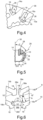
- the magnetic elements 14a, 16a have the respective projections 18 in the region of the radially inner half, i.e. the areas A, which lie behind the respective connecting line 26 of the widest extent of the projections, are smaller than the areas B in front of this connecting line 26.
- the support of the magnetic elements 14a, 16a takes place relatively far radially inward, which reduces the mechanical loads in the radially outer region.
- FIG. 5 a preferred embodiment of the invention is shown, according to which the projections 18 of the magnetic elements 14 (16, 20,22, 24) have support surfaces 28 for centrifugal force support on the rotor 10, the surface tangents 29 of which have an angle ⁇ between 30° and 80° to the direction of extension 30 of the magnetic elements.
- This causes the magnetic element to be displaced against the radial direction, i.e. towards the center of the rotor, during the cooling and associated shrinking process, which increases the gap between the magnetic element and the cavity wall in the area of the radial end.
- the centrifugal forces have a centering and thus stabilizing effect on the magnetic element.
- FIG 6 is an excerpt from Figure 1 which is designated VI there.
- Two adjacent magnetic elements 14b, 16b are shown, between which bridges 36a, 36b are defined by end faces 38a, 38b of the magnetic elements 14b, 16b.
- Opposite end faces 38a, 38b of adjacent magnetic elements 14b, 16b are essentially flat and approximately parallel to one another, at least in a partial area of 50%, which means that the bridges 36a, 36b have an approximately constant cross-section or a constant width over at least half the extent or length.
- the ratio of the smallest width X2 to the largest width X1 within the bridge 36b is less than 1.2 (X1/X2 ⁇ 1.2), i.e. the width of the bridge 36b does not change by more than 20% in this partial area.
- the magnetic losses are reduced by these bridges 36a, 36b with a relatively constant width.
- the projections 18 are arranged on the radially inner end of these magnetic elements 14b, 16b. As a result, their respective rear sides form the radially inner end surfaces 38a, 38b of the respective magnetic elements 14b, 16b and thus extend the bridges 36a, 36b.
- Opposite projections 18', 18" of adjacent magnetic elements 14b, 16b of different magnetic layers II, III are laterally offset from one another in such a way that the shortest distance E from a projection 18' to the nearest projection 18" of the adjacent magnetic element 14b is not less than the shortest distance A of the projection 18' to the side edge of the adjacent magnetic element 16b. This avoids constrictions between radially adjacent magnetic elements 14b, 16b and thus magnetically saturated zones.
Landscapes
- Engineering & Computer Science (AREA)
- Power Engineering (AREA)
- Permanent Field Magnets Of Synchronous Machinery (AREA)
Description
- Die Erfindung betrifft einen Rotor aus einem magnetischen Material eines Synchron-Antriebsmotors mit mehreren Rotorpolen, wobei jede Magnetlage eine Reihe von Magnetelementen umfasst, die durch Spritzgießen oder Gießen und Verfestigen von permanentmagnetischem Material in Rotorkavitäten gebildet sind, wobei mindestens ein Teil der Magnetelemente (jeweils in ihren radial inneren Hälften bezüglich ihrer Erstreckung beidseitig abstehende Vorsprünge zur Abstützung der Fliehkräfte der Magnetelemente am Rotor aufweist. Die Erfindung betrifft ferner einen damit versehenen Synchron-Antriebsmotor sowie ein mit einem solchen Antriebsmotor versehenes Kraftfahrzeug.
- Synchron-Antriebsmotoren werden vielfach als Antriebsmaschine für Elektrofahrzeuge verwendet, weil diese über dem gesamten Geschwindigkeitsbereich ein hohes Drehmoment und damit eine hohe Leistungsdichte aufweisen und bei geringem Gewicht eine hohe Fahrdynamik des angetriebenen Fahrzeugs gewährleisten. Insbesondere weisen derartige Motoren hohe Essonsche Ausnutzungsziffern auf, so dass ein hohes Kosten-Leistungsverhältnis erreicht werden kann.
- Bei Hybrid-Sychronmotoren (HSM) setzt sich das Drehmoment aus zwei Komponenten zusammen, nämlich dem Reluktanzmoment und dem Synchronmoment wobei es wünschenswert ist, den Anteil des Reluktanzmoments am Gesamtdrehmoment so weit wie möglich zu erhöhen, idealerweise 50% oder höher.
- Die Rotoren von Synchron-Antriebsmotoren weisen mehrere Pole auf, wobei jedem Pol vergrabene Magnetlagen zugeordnet werden, die im Wesentlichen U-förmig symmetrisch um die Polmittelachsen (nämlich d-Achse) angeordnet sind und aus einer Reihe von Kavitäten bestehen, in denen Permanentmagneten angeordnet sind.
- Aus der
JP 2000197320A - Aus den Druckschriften
DE 40 33 454 A1 ,DE 10 2013 211858 A1 ,EP 2 858 214 A1 ,WO 2018/024605 A1 undUS 2018/205276 A1 sind Rotoren mit durch Spritzgießverfahren eingebrachten Permanentmagneten bekannt, die seitliche Vorsprünge zur Aufnahme von Fließkräften aufweisen. - Ein Problem dabei ist, dass das eingespritzte Magnetmaterial aufgrund des höheren thermischen Ausdehnungskoeffizienten beim Abkühlvorgang stärker schrumpft als die Umgebung der Kavität und dann im abgekühlten Zustand mit etwas Spiel in der Kavität verbleibt.
- Während des Betriebs wird der so hergestellte Magnet einer sehr hohen Zentrifugalkraft ausgesetzt, wodurch aufgrund des Spiels eine erhöhte Druckbelastung auf den radial äußeren Rand der Kavität wirkt. Insbesondere bei den radial außen liegenden Magneten ist es zur Ausrichtung der magnetischen Ströme und Minimierung von Kurzschlussströmen wünschenswert, nur einen relativ schmalen Steg zum Rotoraußenrand zu belassen, was dann zu unerwünschten Belastungen und Verformungen in derartigen Stegen führen würde.
- Die Aufgabe der Erfindung ist es, eine Geometrie für Magnetelemente eines Rotors bereitzustellen, welche eine möglichst wirksame Aufnahme der Rotationsfliehkräfte ermöglicht.
- Die Erfindung ergibt sich aus den Merkmalen von Anspruch 1. Vorteilhafte Weiterbildungen und Ausgestaltungen sind Gegenstand der abhängigen Ansprüche. Weitere Merkmale, Anwendungsmöglichkeiten und Vorteile der Erfindung ergeben sich aus der nachfolgenden Beschreibung, sowie der Erläuterung von Ausführungsbeispielen der Erfindung, die in der Figur dargestellt sind.
- Die erfindungsgemäße Ausbildung bewirkt eine Abstützmöglichkeit im radial inneren Bereich des Magnetelements, wo genügend Rotormaterial vorhanden ist, um eine problemlose Abstützung zu ermöglichen. Dadurch ist es möglich, ein Anstoßen des radial außen liegenden Endes eines Magnetelements an der Kavitätswandung entweder ganz zu unterbinden, was vor allem bei den radial außen befindlichen Magnetelementen wichtig ist, oder die Druckkräfte gegenüber einem herkömmlichen Magnetelement wesentlich zu reduzieren, was die Belastungen und Verformungen in den Stegen und Brücken zwischen den Magnetelementen bzw. zum Rotoraußenrand vermindert. Da die Vorsprünge Abstützflächen zur Fliehkraftabstützung am Rotor aufweisen, deren Flächentangenten einen Winkel von 30° bis 80° zur Erstreckungsrichtung der Magnetelemente ausgerichtet sind, wird zum einen beim Abkühl- und damit einhergehenden Schrumpfungsprozess eine Verschiebung des Magnetelements entgegen der Radialrichtung, also zur Rotormitte bewirkt, was den Spalt zwischen dem Magnetelement und der Kavitätswandung im Bereich des radialen Endes erhöht. Darüber hinaus wird durch die Fliehkräfte eine zentrierende und damit stabilisierende Wirkung auf das Magnetelement erzielt.
- Gemäß einer vorteilhaften Weiterbildung der Erfindung sind bei Magnetelementen mit dem Längen/Breitenverhältnis von mehr als 3:1 in der äußeren Hälfte zwei weitere beidseitig abstehende Vorsprünge ausgebildet. Diese Ausbildung ist bei derart länglichen Magnetelementen wegen der größeren fliehkraftinduzierten Längenänderung von Vorteil, insbesondere wenn die Längsachsen derartiger Magnetelemente eher radial ausgerichtet sind und daher die Tendenz zur Druckbeaufschlagung der radial äußeren Kavitätswandung durch das Magnetelement besonders hoch ist.
- Gemäß einer vorteilhaften Weiterbildung der Erfindung sind alle Magnetelemente der von radial außen gesehen zweiten und dritten Magnetlage derart ausgebildet. Bei der radial äußersten Magnetlage sind die Magnetelemente relativ tangential ausgerichtet, so dass die Druckbeaufschlagung der Kavitätswandung nur in geringem Maße besteht. Bei der zweiten und noch mehr der dritten Magnetlage sind vor allem die am Rand befindlichen Magnetelemente mehr oder weniger radial ausgerichtet, so dass die erfindungsgemäße Abstützanordnung wirksam ist.
- Gemäß einer alternativen vorteilhaften Weiterbildung der Erfindung sind nur die jeweils radial außen befindlichen Magnetelemente einer Magnetlage derart ausgebildet, weil bei diesen, wie oben erwähnt, eine im Wesentlichen radiale Ausrichtung der Längsachse gegeben ist und damit die Fliehkräfte stärkere Auswirkungen haben.
- Gemäß einer alternativen vorteilhaften Weiterbildung der Erfindung weisen die Flächentangenten einen Winkel 40° bis 60°, zur Erstreckungsrichtung der Magnetelemente aufweisen. Dabei wäre 0 ° die Erstreckungsrichtung selber.
- Gemäß einer vorteilhaften Weiterbildung der Erfindung beträgt die maximale Erstreckung jeder der Vorsprünge normal zur Erstreckungsrichtung der Magnetelemente weniger als 50% der Breite der Magnetelemente an dieser Stelle. Diese Begrenzung dient dazu, nicht allzu viel des Reluktanzflusspfades zu blockieren, da bei dieser Art von Synchronmaschinen große Teile des Moments über den Reluktanzeffekt produziert werden.
- Gemäß einer vorteilhaften Weiterbildung der Erfindung sind sich gegenüberliegende Vorsprünge von benachbarten Magnetelementen verschiedener Magnetlagen derart gegeneinander seitlich versetzt, dass die kürzeste Entfernung von einem Vorsprung zum nächstliegenden Vorsprung des benachbarten Magnetelements nicht geringer ist als die kürzeste Entfernung des Vorsprungs zum Seitenrand des benachbarten Magnetelements. Dadurch wird vorteilhafterweise sichergestellt, dass die Materialstärke des Rotormaterials zwischen benachbarten Magnetlagen weitgehend konstant bleibt und dadurch magnetisch gesättigte Bereiche vermieden werden.
- Gemäß einer vorteilhaften Weiterbildung der Erfindung sind Endflächen von Magnetelementen, die in der gleichen Magnetlage benachbarten Magnetelementen gegenüberliegen und so Brücken zwischen gegenüberliegenden Endflächen von benachbarten Magnetelementen ausbilden, mindestens in einem Teilbereich von 50% im Wesentlichen eben und parallel zueinander derart geformt, dass die Brücken über mindestens der halben Erstreckung einen konstanten Querschnitt aufweisen. Gemäß einer vorteilhaften Weiterbildung dieser Ausbildung verändert sich die Breite der Brücke in diesem Teilbereich um nicht mehr als 20%. Auf diese Weise werden Brücken mit weitgehend konstantem Querschnitt erzielt, was der Minimierung von magnetischen Verlusten dient.
- Gemäß einer vorteilhaften Weiterbildung der Erfindung sind die Vorsprünge jeweils am radial inneren Ende der Magnetelemente angeordnet und deren Rückseiten bilden die radial innere Endfläche des jeweiligen Magnetelements mit aus und verbreitern diese. Dadurch werden Brücken von größerer Erstreckung bei weitgehend konstanter Breite erzielt, was den Vorteil hat, dass der schädliche sogenannte Streufluss einen weiteren Weg hat, wodurch weniger Magnetkraft zu Streufluss wird und somit Drehmoment produziert wird anstatt das Drehmomentrippel, welchen dieser beeinflusst, zu erhöhen.
- Die Erfindung umfasst ferner einen Synchron-Antriebsmotor mit einem Rotor nach einer der vorbeschriebenen Aus- oder Weiterbildungen.
- Weitere Vorteile, Merkmale und Einzelheiten ergeben sich aus der nachfolgenden Beschreibung, in der - gegebenenfalls unter Bezug auf die Zeichnung - zumindest ein Ausführungsbeispiel im Einzelnen beschrieben ist. Gleiche, ähnliche und/oder funktionsgleiche Teile sind mit gleichen Bezugszeichen versehen.
- Es zeigen:
- Figur 1:
- eine schematische Darstellung eines Rotorsektors gemäß einer ersten Ausführungsform der Erfindung,
- Figur 2:
- eine schematische Darstellung eines Rotorsektors gemäß einer zweiten Ausführungsform der Erfindung,
- Figur 3:
- eine schematische Darstellung eines Rotorsektors gemäß einer dritten Ausführungsform der Erfindung,
- Figur 4:
- einen Ausschnitt der Ausführungsform gemäß
Figur 1 , - Figur 5:
- den in
Figur 1 mit V bezeichneten Ausschnitt, - Figur 6:
- den in
Figur 1 mit VI bezeichneten Ausschnitt. - Die
Figuren 1 bis 3 zeigen drei Ausführungsformen von sektorartigen Teilen von Rotoren 10a, 10b, 10c, jeweils symmetrisch bezüglich einer radialen Polachse. Normalerweise hat ein Rotor 10a, 10b, 10c sechs bis zehn Pole, die gleichmäßig über dem Umfang verteilt sind. Radial au ßerhalb des Rotors 10a, 10b, 10c ist jeweils ein nicht gezeigter Stator mit der gleichen Polanzahl angeordnet. - Jeder Pol eines Rotors 10a, 10b, 10c weist mehrere Magnetlagen auf, die jeweils aus einer Reihe von Magnetelementen bestehen. Die Ausführungsform gemäß
Figur 1 umfasst drei Magnetlagen I, II, III. Die erste Magnetlage I besteht aus drei Magnetelementen 12, die eine herkömmliche Gestaltung aufweisen. Die Magnetelemente 14a und 14b haben die erfindungsgemäße Ausgestaltung. In gleicher Weise haben die Magnetelemente 16a und 16b der dritten Magnetlage III die erfindungsgemäße Ausgestaltung. Es sei in diesem Zusammenhang erwähnt, dass im Rahmen der Erfindung jedoch nicht alle Magnetelemente 14, 16 der beiden Magnetlagen eine derartige Ausgestaltung aufweisen müssen. Insbesondere bei den inneren Magnetelementen 14b, 16b, die eine eher tangentiale Ausrichtung aufweisen, kann eine herkömmliche Gestaltung zur Anwendung gelangen. - Die Magnetelemente 14, 16 sind mittels Spritzgießen oder Gießen und Verfestigen von permanentmagnetischem Material in entsprechend geformten Rotorkavitäten gebildet. Die Magnetelemente 14, 16 weisen jeweils in ihren radial inneren Hälften beidseitig abstehende Vorsprünge 18 auf. Die Vorsprünge 18 liegen bei den radial äußeren Magnetelementen 14a, 16a im radial inneren Teil der Magnetelemente 14a, 16a.
- In
Figur 1 ist eine weitere Ausführung von Magnetelementen 16b der Lage III dargestellt, die ein Längen/Breitenverhältnis von mehr als 3:1 (ohne Berücksichtigung der durch die Vorsprünge 18 bewirkten Verbreiterungen) aufweisen, wobei in der radial äußeren Hälfte zwei weitere beidseitig abstehende Vorsprünge 19 ausgebildet sind. Dies bewirkt eine weniger belastende Krafteinleitung der Fliehkräfte der Magnetelemente 16b in den Rotor 10a, weil diese auf vier Vorsprünge 18, 19 aufgeteilt wird. - Die Ausführung gemäß
Figur 2 umfasst lediglich zwei Magnetlagen I und II, wobei alle Magnetelemente 20 sowohl der äußeren Magnetlage I als auch die Magnetelemente 22a, 22b der inneren Magnetlage II die erfindungsgemäße Ausbildung mit beidseitigen Vorsprüngen 18 aufweisen. - Die Ausführung gemäß
Figur 3 umfasst wiederum drei Magnetlagen I, II und III, wobei alle Magnetelemente 20, 22, 24 aller Magnetlagen die erfindungsgemäße Ausbildung mit beidseitigen Vorsprüngen 18 aufweisen. In denFiguren 2 und 3 sind die Magnetelemente 22, 24 der zweiten bzw. dritten Magnetlage II, III geradlinig hintereinander angeordnet. Es ist alternativ im Rahmen der Erfindung selbstverständlich möglich, die Magnetlagen wie inFigur 1 bogenartig auszubilden. - In
Figur 4 ist dargestellt, dass die Magnetelemente 14a, 16a die jeweiligen Vorsprünge 18 im Bereich der radial inneren Hälfte aufweisen, also die Flächen A, die hinter der jeweiligen Verbindungslinie 26 der breitesten Erstreckung der Vorsprünge liegen, kleiner sind als die Flächen B vor dieser Verbindungslinie 26. Dadurch erfolgt die Abstützung der Magnetelemente 14a, 16a relativ weit radial innen, was die mechanischen Belastungen im radial äußeren Bereich vermindert. - In
Figur 5 ist eine bevorzugte Ausbildung der Erfindung dargestellt, wonach die Vorsprünge 18 der Magnetelemente 14 (16, 20,22, 24) Abstützflächen 28 zur Fliehkraftabstützung am Rotor 10 aufweisen, deren Flächentangenten 29 einen Winkel α zwischen 30° bis 80° zur Erstreckungsrichtung 30 der Magnetelemente aufweisen. Dadurch wird beim Abkühl- und damit einhergehenden Schrumpfungsprozess eine Verschiebung des Magnetelements entgegen der Radialrichtung, also zur Rotormitte bewirkt, was den Spalt zwischen dem Magnetelement und der Kavitätswandung im Bereich des radialen Endes erhöht. Darüber hinaus wird durch die Fliehkräfte eine zentrierende und damit stabilisierende Wirkung auf das Magnetelement erzielt. InFigur 5 ist auch ein stark vergrößert dargestellter Spalt 32 zwischen der Kavitätswandung 34 zu sehen, der durch den Schrumpfungsvorgang des Magnetelements 14 entsteht. Die maximale Erstreckung C jeder der Vorsprünge 18 senkrecht zur Erstreckungsrichtung 30 der Magnetelemente 14 (16, 20,22, 24) beträgt weniger als 50% der Breite D der Magnetelemente 14 an dieser Stelle (inFigur 5 ist D/2 dargestellt). - In
Figur 6 ist ein Ausschnitt ausFigur 1 zu sehen, der dort mit VI bezeichnet ist. Dargestellt sind je zwei benachbarte Magnetelemente 14b, 16b, zwischen denen jeweils Brücken 36a, 36b durch Endflächen 38a, 38b der Magnetelemente 14b, 16b definiert sind. Dabei sind gegenüberliegende Endflächen 38a, 38b von benachbarten Magnetelementen 14b, 16b, mindestens in einem Teilbereich von 50% im Wesentlichen eben und näherungsweise parallel zueinander ausgebildet, was dazu führt, dass die Brücken 36a, 36b über mindestens der halben Erstreckung bzw. Länge einen näherungsweise konstanten Querschnitt bzw. eine konstante Breite aufweisen. Mit anderen Worten beträgt über einen Längenabschnitt B, der mindestens die Hälfte der Gesamtlänge A aufweist, das Verhältnis der geringsten Breite X2 zur größten Breite X1 innerhalb der Brücke 36b weniger als 1,2 (X1/X2 < 1,2), also die Breite der Brücke 36b verändert sich in diesem Teilbereich um nicht mehr als 20%. Durch diese Brücken 36a, 36b mit relativ konstanter Breite werden die magnetischen Verluste reduziert. - Die Vorsprünge 18 sind bei diesen Magnetelementen 14b, 16b jeweils am radial inneren Ende dieser Magnetelemente 14b, 16b angeordnet. Dadurch bilden deren jeweilige Rückseiten die radial inneren Endflächen 38a, 38b der jeweiligen Magnetelemente 14b, 16b mit aus und verlängern damit die Brücken 36a, 36b..
- Eine bevorzugte Weiterbildung der Erfindung ist in
Figur 6 dargestellt. Gegenüberliegende Vorsprünge 18', 18" von benachbarten Magnetelementen 14b, 16b verschiedener Magnetlagen II, III sind dabei derart gegeneinander seitlich versetzt, dass die kürzeste Entfernung E von einem Vorsprung 18' zum nächstliegenden Vorsprung 18" des benachbarten Magnetelements 14b nicht geringer ist als die kürzeste Entfernung A des Vorsprungs 18' zum Seitenrand des benachbarten Magnetelements 16b. Dadurch werden Verengungen zwischen radial benachbarten Magnetelementen 14b, 16b und damit magnetisch gesättigte Zonen vermieden - Obwohl die Erfindung im Detail durch bevorzugte Ausführungsbeispiele näher illustriert und erläutert wurde, so ist die Erfindung nicht durch die offenbarten Beispiele eingeschränkt und andere Variationen können vom Fachmann hieraus abgeleitet werden, ohne den Schutzumfang der Erfindung zu verlassen. Es ist daher klar, dass eine Vielzahl von Variationsmöglichkeiten existiert. Es ist ebenfalls klar, dass beispielhaft genannte Ausführungsformen wirklich nur Beispiele darstellen, die nicht in irgendeiner Weise als Begrenzung etwa des Schutzbereichs, der Anwendungsmöglichkeiten oder der Konfiguration der Erfindung aufzufassen sind. Vielmehr versetzen die vorhergehende Beschreibung und die Figurenbeschreibung den Fachmann in die Lage, die beispielhaften Ausführungsformen konkret umzusetzen, wobei der Fachmann in Kenntnis des offenbarten Erfindungsgedankens vielfältige Änderungen beispielsweise hinsichtlich der Funktion oder der Anordnung einzelner, in einer beispielhaften Ausführungsform genannter Elemente vornehmen kann, ohne den Schutzbereich zu verlassen, der durch die Ansprüche und deren rechtliche Entsprechungen, wie etwa einer weitergehenden Erläuterungen in der Beschreibung, definiert wird.
-
- 10a,b,c
- Rotoren
- 12
- Magnetelemente
- 14a,b
- Magnetelemente
- 16a,b
- Magnetelemente
- 18, 18',18"
- Vorsprung
- 19
- Vorsprung
- 20
- Magnetelemente
- 22a,b
- Magnetelemente
- 24a,b
- Magnetelemente
- 26
- Verbindungslinien
- 28
- Abstützfläche
- 29
- Flächentangente
- 30
- Erstreckungsrichtung
- 32
- Spalt
- 34
- Kavitätswandung
- 36a,b
- Brücken
- 38a,b
- Endflächen
Claims (12)
- Rotor (10) aus einem magnetischen Material eines Synchron-Antriebsmotors mit mehreren Rotorpolen, die aus mehreren Magnetlagen (I, II, III) aufgebaut sind,wobei in jeder Magnetlage (I, II, III) eine Reihe von einem oder mehreren Magnetelementen (14, 16, 20, 22, 24) angeordnet ist, die durch Spritzgießen oder Gießen und Verfestigen von permanentmagnetischem Material in Rotorkavitäten eines magnetischen Jochs gebildet sind, wobei mindestens ein Teil der Magnetelemente (14, 16, 20, 22, 24) dessen Längsachsen eher radial ausgerichtet sind, in Bezug auf ihre jeweilige Erstreckung eine radial innere und eine radial äußere Hälfte aufweisen, wobei jeweils in ihren radial inneren Hälften bezüglich ihrer Erstreckung beidseitig der Magnetelemente quer zur Erstreckungsrichtung (30) der Magnetelemente (14, 16, 20, 22, 24) abstehende Vorsprünge (18) zur Abstützung der Fliehkräfte der Magnetelemente am Rotor (10) aufweisen, dadurch gekennzeichnet, dassjeder Rotorpol mindestens zwei radial hinter einander angeordnete Magnetlagen (I, II, III) aufweist, und die Vorsprünge (18, 19) Abstützflächen aufweisen, deren Flächentangenten (29) einen Winkel α von 30° bis 80°zur Erstreckungsrichtung (30) der Magnetelemente aufweisen.
- Rotor nach Anspruch 1, dadurch gekennzeichnet, dass bei Magnetelementen (16b) mit dem Längen/Breitenverhältnis von mehr als 3:1 in der äußeren Hälfte zwei weitere beidseitig abstehende Vorsprünge (19) ausgebildet sind.
- Rotor nach einem der vorherigen Ansprüche, dadurch gekennzeichnet, dass alle Magnetelemente (14, 16, 20, 22, 24) der von radial außen gesehen zweiten und dritten Magnetlage (II, III) derart ausgebildet sind.
- Rotor nach Anspruch 1 oder 2, dadurch gekennzeichnet, dass die jeweils radial außen befindlichen Magnetelemente (14a, 16a, 22a, 24a) einer Magnetlage (I, II, III) derart ausgebildet sind.
- Rotor nach einem der vorherigen Ansprüche, dadurch gekennzeichnet, dass die Vorsprünge (18, 19) Abstützflächen zur Fliehkraftabstützung am Rotor (10) aufweisen, deren Flächentangenten (29) einen Winkel α von 40° bis 60°, zur Erstreckungsrichtung (30) der Magnetelemente aufweisen.
- Rotor nach einem der vorherigen Ansprüche, dadurch gekennzeichnet, dass die maximale Erstreckung (C) jeder der Vorsprünge (18, 19) normal zur Erstreckungsrichtung (30) der Magnetelemente (14, 16, 20, 22, 24) weniger als 50% der Breite (D) der Magnetelemente (14, 16, 20, 22, 24) an dieser Stelle beträgt.
- Rotor nach einem der vorherigen Ansprüche, dadurch gekennzeichnet, dass sich gegenüberliegende Vorsprünge (18', 18") von benachbarten Magnetelementen (14b, 16b) verschiedener Magnetlagen (II, III) derart gegeneinander seitlich versetzt sind, dass die kürzeste Entfernung (E) von einem Vorsprung (18') eines Magnetelements (14b) zum nächstliegenden Vorsprung (18") des benachbarten Magnetelements (16b) nicht geringer ist als die kürzeste Entfernung (A) des Vorsprungs (18') zum Seitenrand des benachbarten Magnetelements (16b).
- Rotor nach einem der vorherigen Ansprüche, dadurch gekennzeichnet, dass Endflächen von Magnetelementen (14b, 16b), die in der gleichen Magnetlage (II, III) benachbarten Magnetelementen (14b, 16b) gegenüber liegen und so Brücken (36a, 36b), zwischen gegenüberliegenden Endflächen (38a, 38b) von benachbarten Magnetelementen (14b, 16b) ausbilden, mindestens in einem Teilbereich von 50% im Wesentlichen eben und parallel zueinander geformt sind, so dass die Brücken (36a, 36b) über mindestens der halben Erstreckung (B) einen konstanten Querschnitt aufweisen.
- Rotor nach Anspruch 8, dadurch gekennzeichnet, dass sich die Breite der Brücke (36) in diesem Teilbereich (B) um nicht mehr als 20% verändert.
- Rotor nach Anspruch 8 oder 9, dadurch gekennzeichnet, dass die Vorsprünge (18) jeweils am radial inneren Ende der Magnetelemente (14b, 16b) angeordnet sind und deren jeweilige Rückseite die radial innere Endfläche (38) des jeweiligen Magnetelements (14b, 16b) mit ausbildet und verbreitert.
- Synchron-Antriebsmotor mit einem Rotor nach einem der vorhergehenden Ansprüche.
- Kraftfahrzeug mit einem Synchron-Antriebsmotor nach Anspruch 11.
Applications Claiming Priority (1)
| Application Number | Priority Date | Filing Date | Title |
|---|---|---|---|
| DE102019107394.4A DE102019107394A1 (de) | 2019-03-22 | 2019-03-22 | Rotor mit gegossenen Magnetelementen mit Vorsprüngen |
Publications (2)
| Publication Number | Publication Date |
|---|---|
| EP3713049A1 EP3713049A1 (de) | 2020-09-23 |
| EP3713049B1 true EP3713049B1 (de) | 2024-06-26 |
Family
ID=69770596
Family Applications (1)
| Application Number | Title | Priority Date | Filing Date |
|---|---|---|---|
| EP20160883.3A Active EP3713049B1 (de) | 2019-03-22 | 2020-03-04 | Rotor mit gegossenen magnetelementen mit vorsprüngen |
Country Status (5)
| Country | Link |
|---|---|
| US (1) | US11489382B2 (de) |
| EP (1) | EP3713049B1 (de) |
| CN (1) | CN111725912A (de) |
| DE (1) | DE102019107394A1 (de) |
| ES (1) | ES2988322T3 (de) |
Families Citing this family (3)
| Publication number | Priority date | Publication date | Assignee | Title |
|---|---|---|---|---|
| FR3113988B1 (fr) | 2020-09-07 | 2023-04-28 | Commissariat Energie Atomique | Dispositif pour la formation de poles d’un rotor |
| CN113131645B (zh) * | 2021-05-21 | 2025-09-16 | 珠海格力节能环保制冷技术研究中心有限公司 | 转子结构及具有其的电机 |
| US20250119009A1 (en) * | 2023-10-09 | 2025-04-10 | GM Global Technology Operations LLC | Rotor for electric machine |
Family Cites Families (15)
| Publication number | Priority date | Publication date | Assignee | Title |
|---|---|---|---|---|
| DE4033454A1 (de) * | 1990-10-20 | 1992-04-23 | Bosch Gmbh Robert | Permanentmagnetrotor |
| JP4089072B2 (ja) * | 1998-10-23 | 2008-05-21 | 三菱電機株式会社 | 永久磁石埋込み形モータ |
| JP2002010547A (ja) * | 2000-06-16 | 2002-01-11 | Yamaha Motor Co Ltd | 永久磁石回転子及びその製造方法 |
| JP2007187283A (ja) * | 2006-01-16 | 2007-07-26 | Shinko Electric Co Ltd | 電磁クラッチ |
| US7556082B2 (en) * | 2006-03-29 | 2009-07-07 | Gm Global Technology Operations, Inc. | Interior permanent magnet rotors with multiple properties and methods of making same |
| DE102009050991A1 (de) * | 2009-10-28 | 2011-05-05 | Bayerische Motoren Werke Aktiengesellschaft | Elektrische Antriebsmaschine für ein Fahrzeug |
| CN102761182B (zh) * | 2011-08-05 | 2013-03-27 | 珠海格力电器股份有限公司 | 电动机转子及具有其的电动机 |
| JP6223968B2 (ja) * | 2012-05-31 | 2017-11-01 | エドワーズ株式会社 | 真空ポンプ用ipmモータ |
| DE102013211858A1 (de) * | 2013-06-21 | 2014-12-24 | Robert Bosch Gmbh | Oberflächen- Magnete und vergrabene Magnete für einen Rotor oder Stator einer elektrischen Maschine, der eine Haltegeometrie aufweist |
| EP3232549B1 (de) * | 2016-04-14 | 2020-12-16 | Levitronix GmbH | Elektromagnetischer drehantrieb und rotationsvorrichtung |
| DE102016114362A1 (de) * | 2016-08-03 | 2018-02-08 | Feaam Gmbh | Rotor für eine elektrische Maschine sowie elektrische Maschine |
| DE102016214542A1 (de) * | 2016-08-05 | 2018-02-08 | Robert Bosch Gmbh | Rotor für eine Synchron-Reluktanzmaschine |
| US20180205276A1 (en) * | 2017-01-13 | 2018-07-19 | United Technologies Corporation | Internal mount permanent magnet attachment for electric machine |
| DE102017201029A1 (de) * | 2017-01-23 | 2018-07-26 | Audi Ag | Rotor für elektrische Maschine |
| US10644576B2 (en) * | 2017-12-30 | 2020-05-05 | Abb Schweiz Ag | Method for manufacturing an electrical machine |
-
2019
- 2019-03-22 DE DE102019107394.4A patent/DE102019107394A1/de not_active Withdrawn
-
2020
- 2020-03-04 EP EP20160883.3A patent/EP3713049B1/de active Active
- 2020-03-04 ES ES20160883T patent/ES2988322T3/es active Active
- 2020-03-13 US US16/818,626 patent/US11489382B2/en active Active
- 2020-03-20 CN CN202010199817.1A patent/CN111725912A/zh active Pending
Also Published As
| Publication number | Publication date |
|---|---|
| US20200303977A1 (en) | 2020-09-24 |
| ES2988322T3 (es) | 2024-11-20 |
| CN111725912A (zh) | 2020-09-29 |
| US11489382B2 (en) | 2022-11-01 |
| DE102019107394A1 (de) | 2020-09-24 |
| EP3713049A1 (de) | 2020-09-23 |
Similar Documents
| Publication | Publication Date | Title |
|---|---|---|
| EP3651316B1 (de) | Rotor für einen synchron-antriebsmotor | |
| EP2951909B1 (de) | Rotor, reluktanzmaschine und herstellungsverfahren für den rotor | |
| DE102010007617B4 (de) | Verfahren und Vorrichtung für eine Permanentmagnetmaschine mit asymmetrischen Rotormagneten | |
| EP2073352B1 (de) | Permanenterregte Synchronmaschine mit Schalenmagneten | |
| EP2688183B1 (de) | Gießtechnisch hergestellte elektrische Spule | |
| EP3084936B1 (de) | Reluktanzrotor aufweisend ein reluktanzrotorblech mit aussparung zur spannungsreduktion | |
| DE69216587T2 (de) | Rotor synchroner drehmaschinen | |
| DE60115758T2 (de) | Permanentmagnetischer Reluktanzmotor | |
| EP3103183B1 (de) | Reluktanzrotor mit mechanischer stabilisierung | |
| EP3248271B1 (de) | Rotor einer asynchronmaschine | |
| EP2494678B1 (de) | Elektrische antriebsmaschine für ein fahrzeug | |
| DE112014006129T5 (de) | Rotierende elektrische Maschine | |
| DE69600160T2 (de) | Anker für eine Reluktanzmaschine | |
| EP3713049A1 (de) | Rotor mit gegossenen magnetelementen mit vorsprüngen | |
| DE112009004504T5 (de) | Rotierende elektrische Maschine und Verfahren zur Herstellung einer rotierenden elektrischen Maschine | |
| DE102018215864A1 (de) | Rotor eines Elektromotors sowie Elektromotor | |
| DE102012219003A1 (de) | Läuferanordnung für eine rotatorische elektrische Maschine | |
| DE102016209711A1 (de) | Rotorkern | |
| WO2022089920A1 (de) | Rotor für eine permanenterregte synchronmaschine und permanenterregte synchronmaschine | |
| EP3314728A1 (de) | Synchrone reluktanzmaschine | |
| EP2957024B1 (de) | Fliehkraftabstützung eines kurzschlussrings bei induktionsmaschinen | |
| EP3618228A1 (de) | Statoranordnung für einen rotatorischen synchronmotor | |
| DE2262045A1 (de) | Turbogenerator | |
| DE69415471T2 (de) | Reluktanz-Synchronmotor mit ausgeprägten Polen und hohem Wirkungsgrad | |
| WO2014166826A2 (de) | Reluktanzmotor mit stabilisiertem rotor |
Legal Events
| Date | Code | Title | Description |
|---|---|---|---|
| PUAI | Public reference made under article 153(3) epc to a published international application that has entered the european phase |
Free format text: ORIGINAL CODE: 0009012 |
|
| STAA | Information on the status of an ep patent application or granted ep patent |
Free format text: STATUS: THE APPLICATION HAS BEEN PUBLISHED |
|
| AK | Designated contracting states |
Kind code of ref document: A1 Designated state(s): AL AT BE BG CH CY CZ DE DK EE ES FI FR GB GR HR HU IE IS IT LI LT LU LV MC MK MT NL NO PL PT RO RS SE SI SK SM TR |
|
| AX | Request for extension of the european patent |
Extension state: BA ME |
|
| STAA | Information on the status of an ep patent application or granted ep patent |
Free format text: STATUS: REQUEST FOR EXAMINATION WAS MADE |
|
| 17P | Request for examination filed |
Effective date: 20210323 |
|
| RBV | Designated contracting states (corrected) |
Designated state(s): AL AT BE BG CH CY CZ DE DK EE ES FI FR GB GR HR HU IE IS IT LI LT LU LV MC MK MT NL NO PL PT RO RS SE SI SK SM TR |
|
| STAA | Information on the status of an ep patent application or granted ep patent |
Free format text: STATUS: EXAMINATION IS IN PROGRESS |
|
| 17Q | First examination report despatched |
Effective date: 20210730 |
|
| REG | Reference to a national code |
Ref country code: DE Ref legal event code: R079 Free format text: PREVIOUS MAIN CLASS: H02K0001270000 Ipc: H02K0001276000 Ref country code: DE Ref legal event code: R079 Ref document number: 502020008345 Country of ref document: DE Free format text: PREVIOUS MAIN CLASS: H02K0001270000 Ipc: H02K0001276000 |
|
| RIC1 | Information provided on ipc code assigned before grant |
Ipc: H02K 1/276 20220101AFI20221114BHEP |
|
| GRAP | Despatch of communication of intention to grant a patent |
Free format text: ORIGINAL CODE: EPIDOSNIGR1 |
|
| STAA | Information on the status of an ep patent application or granted ep patent |
Free format text: STATUS: GRANT OF PATENT IS INTENDED |
|
| INTG | Intention to grant announced |
Effective date: 20230329 |
|
| GRAJ | Information related to disapproval of communication of intention to grant by the applicant or resumption of examination proceedings by the epo deleted |
Free format text: ORIGINAL CODE: EPIDOSDIGR1 |
|
| STAA | Information on the status of an ep patent application or granted ep patent |
Free format text: STATUS: EXAMINATION IS IN PROGRESS |
|
| INTC | Intention to grant announced (deleted) | ||
| GRAS | Grant fee paid |
Free format text: ORIGINAL CODE: EPIDOSNIGR3 |
|
| STAA | Information on the status of an ep patent application or granted ep patent |
Free format text: STATUS: GRANT OF PATENT IS INTENDED |
|
| GRAP | Despatch of communication of intention to grant a patent |
Free format text: ORIGINAL CODE: EPIDOSNIGR1 |
|
| INTG | Intention to grant announced |
Effective date: 20230915 |
|
| RAP1 | Party data changed (applicant data changed or rights of an application transferred) |
Owner name: BRUSA TECHNOLOGY AG |
|
| GRAJ | Information related to disapproval of communication of intention to grant by the applicant or resumption of examination proceedings by the epo deleted |
Free format text: ORIGINAL CODE: EPIDOSDIGR1 |
|
| GRAL | Information related to payment of fee for publishing/printing deleted |
Free format text: ORIGINAL CODE: EPIDOSDIGR3 |
|
| STAA | Information on the status of an ep patent application or granted ep patent |
Free format text: STATUS: EXAMINATION IS IN PROGRESS |
|
| GRAP | Despatch of communication of intention to grant a patent |
Free format text: ORIGINAL CODE: EPIDOSNIGR1 |
|
| STAA | Information on the status of an ep patent application or granted ep patent |
Free format text: STATUS: GRANT OF PATENT IS INTENDED |
|
| INTC | Intention to grant announced (deleted) | ||
| INTG | Intention to grant announced |
Effective date: 20240110 |
|
| GRAF | Information related to payment of grant fee modified |
Free format text: ORIGINAL CODE: EPIDOSCIGR3 |
|
| GRAA | (expected) grant |
Free format text: ORIGINAL CODE: 0009210 |
|
| STAA | Information on the status of an ep patent application or granted ep patent |
Free format text: STATUS: THE PATENT HAS BEEN GRANTED |
|
| AK | Designated contracting states |
Kind code of ref document: B1 Designated state(s): AL AT BE BG CH CY CZ DE DK EE ES FI FR GB GR HR HU IE IS IT LI LT LU LV MC MK MT NL NO PL PT RO RS SE SI SK SM TR |
|
| REG | Reference to a national code |
Ref country code: GB Ref legal event code: FG4D Free format text: NOT ENGLISH |
|
| REG | Reference to a national code |
Ref country code: CH Ref legal event code: EP |
|
| REG | Reference to a national code |
Ref country code: DE Ref legal event code: R096 Ref document number: 502020008345 Country of ref document: DE |
|
| PG25 | Lapsed in a contracting state [announced via postgrant information from national office to epo] |
Ref country code: BG Free format text: LAPSE BECAUSE OF FAILURE TO SUBMIT A TRANSLATION OF THE DESCRIPTION OR TO PAY THE FEE WITHIN THE PRESCRIBED TIME-LIMIT Effective date: 20240626 |
|
| PG25 | Lapsed in a contracting state [announced via postgrant information from national office to epo] |
Ref country code: FI Free format text: LAPSE BECAUSE OF FAILURE TO SUBMIT A TRANSLATION OF THE DESCRIPTION OR TO PAY THE FEE WITHIN THE PRESCRIBED TIME-LIMIT Effective date: 20240626 Ref country code: HR Free format text: LAPSE BECAUSE OF FAILURE TO SUBMIT A TRANSLATION OF THE DESCRIPTION OR TO PAY THE FEE WITHIN THE PRESCRIBED TIME-LIMIT Effective date: 20240626 |
|
| REG | Reference to a national code |
Ref country code: LT Ref legal event code: MG9D |
|
| PG25 | Lapsed in a contracting state [announced via postgrant information from national office to epo] |
Ref country code: GR Free format text: LAPSE BECAUSE OF FAILURE TO SUBMIT A TRANSLATION OF THE DESCRIPTION OR TO PAY THE FEE WITHIN THE PRESCRIBED TIME-LIMIT Effective date: 20240927 |
|
| PG25 | Lapsed in a contracting state [announced via postgrant information from national office to epo] |
Ref country code: LV Free format text: LAPSE BECAUSE OF FAILURE TO SUBMIT A TRANSLATION OF THE DESCRIPTION OR TO PAY THE FEE WITHIN THE PRESCRIBED TIME-LIMIT Effective date: 20240626 |
|
| REG | Reference to a national code |
Ref country code: NL Ref legal event code: MP Effective date: 20240626 |
|
| PG25 | Lapsed in a contracting state [announced via postgrant information from national office to epo] |
Ref country code: NO Free format text: LAPSE BECAUSE OF FAILURE TO SUBMIT A TRANSLATION OF THE DESCRIPTION OR TO PAY THE FEE WITHIN THE PRESCRIBED TIME-LIMIT Effective date: 20240926 Ref country code: LV Free format text: LAPSE BECAUSE OF FAILURE TO SUBMIT A TRANSLATION OF THE DESCRIPTION OR TO PAY THE FEE WITHIN THE PRESCRIBED TIME-LIMIT Effective date: 20240626 Ref country code: HR Free format text: LAPSE BECAUSE OF FAILURE TO SUBMIT A TRANSLATION OF THE DESCRIPTION OR TO PAY THE FEE WITHIN THE PRESCRIBED TIME-LIMIT Effective date: 20240626 Ref country code: GR Free format text: LAPSE BECAUSE OF FAILURE TO SUBMIT A TRANSLATION OF THE DESCRIPTION OR TO PAY THE FEE WITHIN THE PRESCRIBED TIME-LIMIT Effective date: 20240927 Ref country code: FI Free format text: LAPSE BECAUSE OF FAILURE TO SUBMIT A TRANSLATION OF THE DESCRIPTION OR TO PAY THE FEE WITHIN THE PRESCRIBED TIME-LIMIT Effective date: 20240626 Ref country code: BG Free format text: LAPSE BECAUSE OF FAILURE TO SUBMIT A TRANSLATION OF THE DESCRIPTION OR TO PAY THE FEE WITHIN THE PRESCRIBED TIME-LIMIT Effective date: 20240626 Ref country code: RS Free format text: LAPSE BECAUSE OF FAILURE TO SUBMIT A TRANSLATION OF THE DESCRIPTION OR TO PAY THE FEE WITHIN THE PRESCRIBED TIME-LIMIT Effective date: 20240926 |
|
| PG25 | Lapsed in a contracting state [announced via postgrant information from national office to epo] |
Ref country code: NL Free format text: LAPSE BECAUSE OF FAILURE TO SUBMIT A TRANSLATION OF THE DESCRIPTION OR TO PAY THE FEE WITHIN THE PRESCRIBED TIME-LIMIT Effective date: 20240626 |
|
| REG | Reference to a national code |
Ref country code: ES Ref legal event code: FG2A Ref document number: 2988322 Country of ref document: ES Kind code of ref document: T3 Effective date: 20241120 |
|
| PG25 | Lapsed in a contracting state [announced via postgrant information from national office to epo] |
Ref country code: NL Free format text: LAPSE BECAUSE OF FAILURE TO SUBMIT A TRANSLATION OF THE DESCRIPTION OR TO PAY THE FEE WITHIN THE PRESCRIBED TIME-LIMIT Effective date: 20240626 |
|
| PG25 | Lapsed in a contracting state [announced via postgrant information from national office to epo] |
Ref country code: PT Free format text: LAPSE BECAUSE OF FAILURE TO SUBMIT A TRANSLATION OF THE DESCRIPTION OR TO PAY THE FEE WITHIN THE PRESCRIBED TIME-LIMIT Effective date: 20241028 |
|
| PG25 | Lapsed in a contracting state [announced via postgrant information from national office to epo] |
Ref country code: PT Free format text: LAPSE BECAUSE OF FAILURE TO SUBMIT A TRANSLATION OF THE DESCRIPTION OR TO PAY THE FEE WITHIN THE PRESCRIBED TIME-LIMIT Effective date: 20241028 |
|
| PG25 | Lapsed in a contracting state [announced via postgrant information from national office to epo] |
Ref country code: PL Free format text: LAPSE BECAUSE OF FAILURE TO SUBMIT A TRANSLATION OF THE DESCRIPTION OR TO PAY THE FEE WITHIN THE PRESCRIBED TIME-LIMIT Effective date: 20240626 |
|
| PG25 | Lapsed in a contracting state [announced via postgrant information from national office to epo] |
Ref country code: EE Free format text: LAPSE BECAUSE OF FAILURE TO SUBMIT A TRANSLATION OF THE DESCRIPTION OR TO PAY THE FEE WITHIN THE PRESCRIBED TIME-LIMIT Effective date: 20240626 |
|
| PG25 | Lapsed in a contracting state [announced via postgrant information from national office to epo] |
Ref country code: IS Free format text: LAPSE BECAUSE OF FAILURE TO SUBMIT A TRANSLATION OF THE DESCRIPTION OR TO PAY THE FEE WITHIN THE PRESCRIBED TIME-LIMIT Effective date: 20241026 |
|
| PG25 | Lapsed in a contracting state [announced via postgrant information from national office to epo] |
Ref country code: CZ Free format text: LAPSE BECAUSE OF FAILURE TO SUBMIT A TRANSLATION OF THE DESCRIPTION OR TO PAY THE FEE WITHIN THE PRESCRIBED TIME-LIMIT Effective date: 20240626 |
|
| PG25 | Lapsed in a contracting state [announced via postgrant information from national office to epo] |
Ref country code: RO Free format text: LAPSE BECAUSE OF FAILURE TO SUBMIT A TRANSLATION OF THE DESCRIPTION OR TO PAY THE FEE WITHIN THE PRESCRIBED TIME-LIMIT Effective date: 20240626 Ref country code: SK Free format text: LAPSE BECAUSE OF FAILURE TO SUBMIT A TRANSLATION OF THE DESCRIPTION OR TO PAY THE FEE WITHIN THE PRESCRIBED TIME-LIMIT Effective date: 20240626 |
|
| PG25 | Lapsed in a contracting state [announced via postgrant information from national office to epo] |
Ref country code: SM Free format text: LAPSE BECAUSE OF FAILURE TO SUBMIT A TRANSLATION OF THE DESCRIPTION OR TO PAY THE FEE WITHIN THE PRESCRIBED TIME-LIMIT Effective date: 20240626 |
|
| PG25 | Lapsed in a contracting state [announced via postgrant information from national office to epo] |
Ref country code: SM Free format text: LAPSE BECAUSE OF FAILURE TO SUBMIT A TRANSLATION OF THE DESCRIPTION OR TO PAY THE FEE WITHIN THE PRESCRIBED TIME-LIMIT Effective date: 20240626 Ref country code: SK Free format text: LAPSE BECAUSE OF FAILURE TO SUBMIT A TRANSLATION OF THE DESCRIPTION OR TO PAY THE FEE WITHIN THE PRESCRIBED TIME-LIMIT Effective date: 20240626 Ref country code: RO Free format text: LAPSE BECAUSE OF FAILURE TO SUBMIT A TRANSLATION OF THE DESCRIPTION OR TO PAY THE FEE WITHIN THE PRESCRIBED TIME-LIMIT Effective date: 20240626 Ref country code: PL Free format text: LAPSE BECAUSE OF FAILURE TO SUBMIT A TRANSLATION OF THE DESCRIPTION OR TO PAY THE FEE WITHIN THE PRESCRIBED TIME-LIMIT Effective date: 20240626 Ref country code: IS Free format text: LAPSE BECAUSE OF FAILURE TO SUBMIT A TRANSLATION OF THE DESCRIPTION OR TO PAY THE FEE WITHIN THE PRESCRIBED TIME-LIMIT Effective date: 20241026 Ref country code: EE Free format text: LAPSE BECAUSE OF FAILURE TO SUBMIT A TRANSLATION OF THE DESCRIPTION OR TO PAY THE FEE WITHIN THE PRESCRIBED TIME-LIMIT Effective date: 20240626 Ref country code: CZ Free format text: LAPSE BECAUSE OF FAILURE TO SUBMIT A TRANSLATION OF THE DESCRIPTION OR TO PAY THE FEE WITHIN THE PRESCRIBED TIME-LIMIT Effective date: 20240626 |
|
| REG | Reference to a national code |
Ref country code: DE Ref legal event code: R097 Ref document number: 502020008345 Country of ref document: DE |
|
| PG25 | Lapsed in a contracting state [announced via postgrant information from national office to epo] |
Ref country code: DK Free format text: LAPSE BECAUSE OF FAILURE TO SUBMIT A TRANSLATION OF THE DESCRIPTION OR TO PAY THE FEE WITHIN THE PRESCRIBED TIME-LIMIT Effective date: 20240626 |
|
| PLBE | No opposition filed within time limit |
Free format text: ORIGINAL CODE: 0009261 |
|
| STAA | Information on the status of an ep patent application or granted ep patent |
Free format text: STATUS: NO OPPOSITION FILED WITHIN TIME LIMIT |
|
| 26N | No opposition filed |
Effective date: 20250327 |
|
| PGFP | Annual fee paid to national office [announced via postgrant information from national office to epo] |
Ref country code: ES Payment date: 20250416 Year of fee payment: 6 |
|
| PGFP | Annual fee paid to national office [announced via postgrant information from national office to epo] |
Ref country code: IT Payment date: 20250331 Year of fee payment: 6 |
|
| PG25 | Lapsed in a contracting state [announced via postgrant information from national office to epo] |
Ref country code: SE Free format text: LAPSE BECAUSE OF FAILURE TO SUBMIT A TRANSLATION OF THE DESCRIPTION OR TO PAY THE FEE WITHIN THE PRESCRIBED TIME-LIMIT Effective date: 20240626 |
|
| PG25 | Lapsed in a contracting state [announced via postgrant information from national office to epo] |
Ref country code: MC Free format text: LAPSE BECAUSE OF FAILURE TO SUBMIT A TRANSLATION OF THE DESCRIPTION OR TO PAY THE FEE WITHIN THE PRESCRIBED TIME-LIMIT Effective date: 20240626 |
|
| REG | Reference to a national code |
Ref country code: CH Ref legal event code: H13 Free format text: ST27 STATUS EVENT CODE: U-0-0-H10-H13 (AS PROVIDED BY THE NATIONAL OFFICE) Effective date: 20251023 |
|
| PG25 | Lapsed in a contracting state [announced via postgrant information from national office to epo] |
Ref country code: LU Free format text: LAPSE BECAUSE OF NON-PAYMENT OF DUE FEES Effective date: 20250304 |
|
| REG | Reference to a national code |
Ref country code: BE Ref legal event code: MM Effective date: 20250331 |
|
| PG25 | Lapsed in a contracting state [announced via postgrant information from national office to epo] |
Ref country code: BE Free format text: LAPSE BECAUSE OF NON-PAYMENT OF DUE FEES Effective date: 20250331 |
|
| PG25 | Lapsed in a contracting state [announced via postgrant information from national office to epo] |
Ref country code: CH Free format text: LAPSE BECAUSE OF NON-PAYMENT OF DUE FEES Effective date: 20250331 |
|
| PG25 | Lapsed in a contracting state [announced via postgrant information from national office to epo] |
Ref country code: IE Free format text: LAPSE BECAUSE OF NON-PAYMENT OF DUE FEES Effective date: 20250304 |
|
| PGFP | Annual fee paid to national office [announced via postgrant information from national office to epo] |
Ref country code: GB Payment date: 20260324 Year of fee payment: 7 |
|
| PGFP | Annual fee paid to national office [announced via postgrant information from national office to epo] |
Ref country code: DE Payment date: 20260324 Year of fee payment: 7 |
|
| PGFP | Annual fee paid to national office [announced via postgrant information from national office to epo] |
Ref country code: FR Payment date: 20260324 Year of fee payment: 7 |
|
| PGFP | Annual fee paid to national office [announced via postgrant information from national office to epo] |
Ref country code: TR Payment date: 20260227 Year of fee payment: 7 |