EP3712096A1 - Method for correcting meander in non-contact transport device for strip substrate, and device for same - Google Patents
Method for correcting meander in non-contact transport device for strip substrate, and device for same Download PDFInfo
- Publication number
- EP3712096A1 EP3712096A1 EP18878100.9A EP18878100A EP3712096A1 EP 3712096 A1 EP3712096 A1 EP 3712096A1 EP 18878100 A EP18878100 A EP 18878100A EP 3712096 A1 EP3712096 A1 EP 3712096A1
- Authority
- EP
- European Patent Office
- Prior art keywords
- strip material
- floater
- roll
- cant
- meandering
- Prior art date
- Legal status (The legal status is an assumption and is not a legal conclusion. Google has not performed a legal analysis and makes no representation as to the accuracy of the status listed.)
- Granted
Links
Images


Classifications
-
- B—PERFORMING OPERATIONS; TRANSPORTING
- B65—CONVEYING; PACKING; STORING; HANDLING THIN OR FILAMENTARY MATERIAL
- B65H—HANDLING THIN OR FILAMENTARY MATERIAL, e.g. SHEETS, WEBS, CABLES
- B65H23/00—Registering, tensioning, smoothing or guiding webs
- B65H23/04—Registering, tensioning, smoothing or guiding webs longitudinally
- B65H23/24—Registering, tensioning, smoothing or guiding webs longitudinally by fluid action, e.g. to retard the running web
-
- B—PERFORMING OPERATIONS; TRANSPORTING
- B65—CONVEYING; PACKING; STORING; HANDLING THIN OR FILAMENTARY MATERIAL
- B65H—HANDLING THIN OR FILAMENTARY MATERIAL, e.g. SHEETS, WEBS, CABLES
- B65H20/00—Advancing webs
- B65H20/02—Advancing webs by friction roller
-
- B—PERFORMING OPERATIONS; TRANSPORTING
- B65—CONVEYING; PACKING; STORING; HANDLING THIN OR FILAMENTARY MATERIAL
- B65H—HANDLING THIN OR FILAMENTARY MATERIAL, e.g. SHEETS, WEBS, CABLES
- B65H20/00—Advancing webs
- B65H20/14—Advancing webs by direct action on web of moving fluid
-
- B—PERFORMING OPERATIONS; TRANSPORTING
- B65—CONVEYING; PACKING; STORING; HANDLING THIN OR FILAMENTARY MATERIAL
- B65H—HANDLING THIN OR FILAMENTARY MATERIAL, e.g. SHEETS, WEBS, CABLES
- B65H23/00—Registering, tensioning, smoothing or guiding webs
-
- B—PERFORMING OPERATIONS; TRANSPORTING
- B65—CONVEYING; PACKING; STORING; HANDLING THIN OR FILAMENTARY MATERIAL
- B65H—HANDLING THIN OR FILAMENTARY MATERIAL, e.g. SHEETS, WEBS, CABLES
- B65H23/00—Registering, tensioning, smoothing or guiding webs
- B65H23/02—Registering, tensioning, smoothing or guiding webs transversely
- B65H23/032—Controlling transverse register of web
- B65H23/038—Controlling transverse register of web by rollers
-
- C—CHEMISTRY; METALLURGY
- C21—METALLURGY OF IRON
- C21D—MODIFYING THE PHYSICAL STRUCTURE OF FERROUS METALS; GENERAL DEVICES FOR HEAT TREATMENT OF FERROUS OR NON-FERROUS METALS OR ALLOYS; MAKING METAL MALLEABLE, e.g. BY DECARBURISATION OR TEMPERING
- C21D9/00—Heat treatment, e.g. annealing, hardening, quenching or tempering, adapted for particular articles; Furnaces therefor
- C21D9/52—Heat treatment, e.g. annealing, hardening, quenching or tempering, adapted for particular articles; Furnaces therefor for wires; for strips ; for rods of unlimited length
- C21D9/54—Furnaces for treating strips or wire
- C21D9/56—Continuous furnaces for strip or wire
- C21D9/63—Continuous furnaces for strip or wire the strip being supported by a cushion of gas
-
- B—PERFORMING OPERATIONS; TRANSPORTING
- B65—CONVEYING; PACKING; STORING; HANDLING THIN OR FILAMENTARY MATERIAL
- B65H—HANDLING THIN OR FILAMENTARY MATERIAL, e.g. SHEETS, WEBS, CABLES
- B65H2404/00—Parts for transporting or guiding the handled material
- B65H2404/10—Rollers
- B65H2404/15—Roller assembly, particular roller arrangement
- B65H2404/152—Arrangement of roller on a movable frame
- B65H2404/1521—Arrangement of roller on a movable frame rotating, pivoting or oscillating around an axis, e.g. parallel to the roller axis
- B65H2404/15212—Arrangement of roller on a movable frame rotating, pivoting or oscillating around an axis, e.g. parallel to the roller axis rotating, pivoting or oscillating around an axis perpendicular to the roller axis
-
- B—PERFORMING OPERATIONS; TRANSPORTING
- B65—CONVEYING; PACKING; STORING; HANDLING THIN OR FILAMENTARY MATERIAL
- B65H—HANDLING THIN OR FILAMENTARY MATERIAL, e.g. SHEETS, WEBS, CABLES
- B65H2701/00—Handled material; Storage means
- B65H2701/10—Handled articles or webs
- B65H2701/17—Nature of material
- B65H2701/173—Metal
Definitions
- This invention relates to a method for correcting meandering of a strip material in a non-contact conveying apparatus of a strip material that performs conveyance of a continuously travelling strip material at a non-contact state with conveyance rolls while floating the strip material by a floater group comprising one or more floaters, and a device for correcting the meandering by using such a method.
- the manufacturing process of steel products includes some steps for subjecting a strip material such as cold rolled steel strip to various treatments such as heat treatment, plating treatment, painting treatment and so on while keeping the strip material travel continuously.
- a strip material such as cold rolled steel strip
- various treatments such as heat treatment, plating treatment, painting treatment and so on while keeping the strip material travel continuously.
- roll conveyance in which the strip material is conveyed while being supported in contact with a roll is usually used as a means for the conveyance of the strip material.
- the conventional roll conveyance method has problems that, for example, in a step when a strip material such as cold rolled steel strip is coated on its surface with various coatings, then dried and baked or when a strip material is subjected to a heat treatment at a high temperature while travelling continuously, defects such as scratches, scraping and the like are easily caused on the material surface or coated film due to the contact between the strip material and the conveyance roll.
- a non-contact conveying apparatus for the conveyance of a strip material at a non-contact state with the conveyance roll by using a floater which can float the strip material by a gaseous pressure or the like.
- the non-contact conveying apparatus Since the strip material is floated in the non-contact conveying apparatus that uses such a floater, the friction force caused by the contact with a supporter is not developed. Therefore, it is pointed out that the non-contact conveying apparatus has a problem in the sheet passing stability that the strip material is slipped laterally to cause meandering or flapped by air draft or the like jetted to float the strip material. Many examinations have been made to prevent the floated strip material from meandering and flapping for stable conveyance of the strip material.
- Patent Literature 1 proposes a conveyance method of a strip material by using a floater that supports the strip material at a non-contact state like a catenary form by jetting gas in which a side plate having a height higher than a usual conveyance level of the strip material is arranged outside each widthwise end portion of the strip material above the floater, whereby a meandering strip material can be conveyed without each widthwise end portion thereof coming in contact with the side plate.
- Patent Literature 2 discloses a device for preventing meandering of a strip material by arranging a steering roll at an outlet side of a horizontal floater for floating a travelling strip material, winding the strip material therearound, and swinging the steering roll so as to forcibly correct the meandering of the strip material.
- the invention is made in view of the above problems inherent to the prior art, and an object thereof is to propose a method for correcting meandering of a strip material in a conveying apparatus for the strip material at a non-contact state while floating the strip material by jetting gas or the like, in which, even when the meandering amount of the strip material is small, the meandering of the strip material can be corrected to perform stable conveyance without adversely affecting the surface of the strip material and to provide a device for correcting the meandering.
- the invention proposes a method for correcting meandering of a strip material in an apparatus that performs conveyance of a continuously travelling strip material at a non-contact state while floating the strip material by a floater group comprising one or more floaters arranged in line, characterized in that the strip material is tilted by forcibly changing a height position in the widthwise direction of the strip material in at least one of a zone between the most upstream floater in the floater group and a conveyance roll located immediately upstream of such a floater, a zone between two adjacent floaters, and a zone between the most downstream floater in the floater group and a conveyance roll located immediately downstream of such a floater to change the height position in the widthwise direction of the strip material above the floater, whereby a static pressure applied to the strip material above the floater is changed to correct meandering thereof.
- the method for correcting meandering of a strip material according to the invention is characterized in that a cant roll is arranged in the zone where the strip material is tilted so as to come in contact with the lower face of the travelling strip material and push up the strip material and the cant roll is tilted with respect to a horizontal surface to change the height position of the cant roll in the widthwise direction of the strip material, whereby the strip material is tilted.
- the method for correcting meandering of a strip material according to the invention is characterized in that an arrangement distance of the cant roll falls within S/2 from the center of the floater, where S is a distance between a center of the most upstream floater in the floater group and a center of the conveyance roll located immediately upstream of such a floater, a distance between the centers of the two adjacent floaters, or a distance between a center of the most downstream floater in the floater group and a center of the conveyance roll located immediately downstream of such a floater.
- the method for correcting meandering of a strip material according to the invention is characterized in that a pushing-up amount L of the cant roll falls within the range of H/3 to 6H with respect to a pass line of the strip material before the arrangement of the cant roll, where H is an average floating amount of the strip material above the floater.
- the method for correcting meandering of a strip material according to the invention is characterized in that a tilt angle of the cant roll falls within the range of ⁇ 0.3 to 5° with respect to a horizontal surface.
- the method for correcting meandering of a strip material according to the invention is characterized in that the tilt angle of the cant roll is controlled by feed-back control and/or feed-forward control based on measurement results of the meandering amount of the strip material.
- the method for correcting meandering of a strip material according to the invention is characterized in that a peripheral speed of the cant roll is controlled within the range of ⁇ 4 m/min with respect to a conveyance speed of the strip material.
- the invention is a device for correcting meandering of a strip material in an apparatus that performs conveyance of a continuously travelling strip material at a non-contact state while floating the strip material by a floater group comprising one or more floaters arranged in line, characterized in that the device is provided with a tilting means for correcting meandering of a strip material in at least one of a zone between the most upstream floater in the floater group and a conveyance roll located immediately upstream of the floater, a zone between two adjacent floaters, and a zone between the most downstream floater in the floater group and a conveyance roll located immediately downstream of such a floater and the tilting means forcibly changes the height position in the widthwise direction of the strip material to tilt thereof and change the height position in the widthwise direction of the strip material above the floater, whereby a static pressure applied to the strip material above the floater is changed to correct meandering thereof.
- the device for correcting meandering of a strip material is characterized the tilting means for correcting meandering of the strip material is provided with a cant roll arranged so as to come in contact with the lower face of the travelling strip material and push up the strip material in the zone where the strip material is tilted and the cant roll is tilted with respect to a horizontal surface to change a height position of the cant roll in the widthwise direction of the strip material, whereby the strip material is tilted.
- the device for correcting meandering of a strip material according to the invention is characterized in that the cant roll is arranged in a position within S/2 from the center of the floater, where S is a distance between a center of the most upstream floater in the floater group and a center of the conveyance roll located immediately upstream of such a floater, a distance between the centers of the two adjacent floaters, or a distance between a center of the most downstream floater in the floater group and a center of the conveyance roll located immediately downstream of such a floater.
- the device for correcting meandering of a strip material according to the invention is characterized in that the cant roll can push up the strip material within the range of H/3 to 6H with respect to a pass line of the strip material before the arrangement of the cant roll, where H is an average floating amount of the strip material above the floater.
- the device for correcting meandering of a strip material according to the invention is characterized in that the tilt angle of the cant roll can be controlled within the range of ⁇ 0.3 to 5° to a horizontal surface.
- the device for correcting meandering of a strip material according to the invention is characterized in that the tilt angle of the cant roll is controlled by feed-back control and/or feed-forward control based on measurement results of the meandering amount of the strip material.
- the strip material in the conveying apparatus for conveying a continuously travelling strip material at a non-contact state with a conveyance roll while floating the strip material by the floater, is forcibly tilted in a zone other than ones where the strip material is floated by the floater to thereby correct meandering of the strip material, so that the strip material can be returned to a center position in the widthwise direction even at a slight meandering amount, whereby it is possible to convey the strip material stably.
- FIG. 1 is a side view of a floater that performs conveyance of a continuously travelling strip material at a floated state which can be used in the invention as an example.
- the floater is to convey the strip material at a floated state by jetting gas toward a lower face of the strip material from underneath thereof.
- a floater 2 is arranged underneath a travelling strip material 1.
- the pressure in the interior of the floater 2 is made higher than atmospheric pressure by feeding gas from a fan, a blower or the like not shown.
- the high-pressure gas in the interior of the floater 2 is jetted from a slit-like gas jetting port (slit nozzle) 5 disposed on the top portion of the floater 2 in the widthwise direction of the strip material toward the lower face of the strip material.
- the slit nozzle 5 is arranged at two places in the travelling direction of the strip material, and the gas jetting directions from these slit nozzles are opposite to each other. Therefore, the gas jetted from the slit nozzle 5 is confined between the strip material 1 and a top plate 6 located in a top portion of the floater to generate a static pressure, and the strip material 1 is supported at a floating state by the static pressure.
- FIG. 2 is a sectional view of the floater taken along a line A-A in FIG. 1 .
- a plurality of rib plates 4 are stood on the top plate 6 in the top portion of the floater at a given interval in the widthwise direction of the strip material.
- the rib plates 4 prevent the outflow of the gas that is jetted from the slit nozzle 5 toward the widthwise direction to stably generate static pressure between the strip material 1 and the top plate 6, whereby the strip material 1 can be floated stably.
- a plurality of rib plates may be stood in the travelling direction of the strip material from a viewpoint of suppressing outflow of the gas jetted from the slit nozzle 5 toward the travelling direction of the strip material.
- Side plates 3 having a height higher than that of the rib plates 4 are stood on both outer sides of the rib plates 4 or on both widthwise end portions of the top plate 6 in the widthwise direction of the strip material to prevent the meandering of the strip material.
- the floater shown in FIGS. 1 and 2 has for correcting meandering of a strip material, with reference to FIG. 3 .
- the gas pathway between the side plate 3 at the meandering side and the strip material 1 is made narrow, so that static pressure generated in the lower face of the strip material 1 increases.
- the floating amount of the strip material 1 at the meandering side increases, and the strip material 1 is rendered into a tilted state as shown in FIG. 3 .
- the static pressure applied to the lower face of the strip material 1 acts as a force in a direction perpendicular to the surface of the strip material.
- This force can be divided into vectors of a vertical force and a horizontal force.
- the vertical force is a floating force supporting the deadweight of the strip material 1
- the horizontal force acts as a correction force for correcting meandering of the strip material 1. That is, when the strip material 1 is tilted above the floater, a component force in the horizontal direction of the static pressure applied to the lower face is generated, and the component force acts as a correction force for correcting the meandering. As a result, the strip material 1 can be conveyed above the floater without continuing the meandering.
- the above conventional floater is effective to large meandering but hardly expected to have the meandering correction force to small meandering.
- the inventors have studied for a meandering correction method effective to the small meandering, taking account of the above-described performance of the floater, and, as a result, have conceived of an idea of tilting the strip material by forcibly changing the height position in the widthwise direction thereof so that the height position in the widthwise direction of the strip material above the floater is changed, and thus the static pressure applied to the strip material above the floater is changed, whereby the meandering correction force can be generated even in the small meandering amount, and the invention has been accomplished.
- the cant roll may be arranged at least one of a zone between the most upstream floater in the floater group and a conveyance roll located immediately upstream of such a floater, a zone between two adjacent floaters, and a zone between the most downstream floater in the floater group and a conveyance roll located immediately downstream of such a floater.
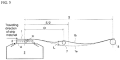
- the arrangement position of the cant roll (arrangement distance D of the cant roll from a center of the floater) is preferably within S/2, where S is a distance between a center of the most upstream floater in the floater group and a center of the conveyance roll located immediately upstream of such a floater, a distance between the centers of the two adjacent floaters, or a distance between a center of the most downstream floater in the floater group and a center of the conveyance roll located immediately downstream of such a floater.
- the cant roll is preferably arranged at the side closer to the floater than the lowest point of a suspending curve (catenary) formed by the strip material between the most upstream floater and the conveyance roll located immediately upstream of such a floater, between the two adjacent floaters, and between the most downstream floater and the conveyance roll located immediately downstream of such a floater.
- a suspending curve catenary
- FIG. 5 shows an example that the distance between the center of the most downstream floater and the center of the conveyance roll located immediately downstream of such a floater is S.
- the arrangement of the cant roll causes the strip material to come in contact with the cant roll and generates a friction force therebetween, which may lead a case that the surface of the strip material is badly affected.
- the cant roll is disposed between the most downstream floater in the floater group and the conveyance roll located immediately downstream of such a floater, or at a position where heat treatment, painting treatment and the like are almost completed, whereby the above bad influence can be suppressed to a minimum level.
- the cant roll is in contact with the strip material, but the most part of the deadweight of the strip material is supported by the floater and the conveyance rolls located immediately upstream and immediately downstream of the floater, so that the friction force generated due to the contact is sufficiently small as compared to that in the usual roll conveyance and does not damage the product quality remarkably.
- An amount that the cant roll pushes up the strip material in contact with the lower face is preferably within the range of H/3 to 6H with respect to a pass line of the strip material before the arrangement of the cant roll, where H is an average floating amount of the strip material above the floater.
- the pushing-up amount L is defined as a distance from a position of the pass line of the strip material before the arrangement of the cant roll, or a pass line position of a catenary formed by the strip material before the arrangement of the cant roll to a pass line position of a catenary formed by the strip material after the pushing up with the cant roll and before the tilting of the cant roll as shown in FIG. 5 .
- the average floating amount H is defined as an average value of a distance from the strip material to the top portion of the rib plate over a full width when the rib plate is present also as shown in FIG. 5 or an average value of a distance from the strip material to the top plate of the floater over the full width when the rib plate is not present.
- the pushing-up amount L is less than H/3, the effect of tilting the strip material above the floater is deteriorated and the meandering correction performance lowers.
- the pushing-up amount L exceeds 6H, a greater part of the deadweight of the strip material is supported by the cant roll, and the static pressure between the top plate of the floater and the strip material decreases, so that the meandering correction performance cannot be obtained sufficiently even when the strip material is tilted. More preferably, the pushing-up amount L falls within the range of H ⁇ L ⁇ 4H.
- the pushing-up mechanism of the cant roll may be such that the pushing-up amount can be freely adjusted, and may use, for example, a power-operated cylinder, a hydraulic cylinder and so on. Also, the pushing-up mechanism is preferable to have such an evacuation function that the cant roll does not come in contact with the strip material when not in use.
- the tilt angle ⁇ of the cant roll in the meandering correction preferably falls within the range of ⁇ 0.3 to 5° to a horizontal surface.
- the absolute value of the tilt angle ⁇ is less than 0.3°, the tilt amount of the strip material is so small that the sufficient meandering correction performance cannot be developed.
- the absolute value of the tilt angle ⁇ exceeds 5°, the tilt amount of the strip material is so large that the floating of the strip material becomes unstable and horizontal oscillation increases, leading the contact with the side plate. More preferably, it falls within the range of ⁇ 1 to 4°.
- the meandering rate is very fast in the conveying apparatus, where the strip material is floated by the floater and the like, and the friction force (restraining force in the widthwise direction) is not exerted on the strip material, so that it is necessary to control the generated meandering in a good responsivity.
- the meandering amount is measured at an exit side of the conveying apparatus (floater group) and the tilt angle ⁇ of the cant roll is controlled by feedback of the measurement value on the meandering correction device arranged at the upstream side, or the meandering amount is measured at an entry side of the conveying apparatus (floater group) and the tilt angle ⁇ of the cant roll is controlled by feedforward of the measurement value on the meandering correction device disposed at the downstream side.
- the shape of the strip material is measured at a stage before the step in the conveying apparatus and the meandering tendency is predicted from the measurement result and the tilt angle ⁇ of the cant roll is controlled by feedforward of the prediction on the meandering correction apparatus disposed in the conveying apparatus.
- the cant roll comes in contact with the strip material.
- surface defects such as scratch and the like might be caused on the surface of the strip material when the threading speed (conveyance speed) of the strip material is not coincident with the rotating speed (peripheral speed) of the cant roll.
- the difference between the conveyance speed of the strip material and the peripheral speed of the cant roll is controlled preferably within ⁇ 4 m/min, irrespectively of the value of the conveyance speed. More preferably, it is within ⁇ 2 m/min.
- the cant roll used in the invention is preferably made from a material durable to a higher temperature and a corrosive environment inside an annealing furnace or a drying furnace.
- a ceramic roll, a metal-sprayed roll, a heat-resistant steel roll and so on are favorably used.
- the surface of the roll is preferably low in the friction coefficient and slippery when being in contact with the strip material, because it is advantageous to the damage of the strip material or the meandering correction. Therefore, the surface of the cant roll is preferably polished to have a surface roughness of about not more than 6 ⁇ m as an arithmetic average roughness Ra.
- the cant roll is disposed fully separated from the high temperature zone and a heat insulating material, a gas cooling device, a water cooling device and the like are disposed in the roll bearing and the sealing member.
- a meandering correction device using a cant roll shown in FIG. 4 is arranged between the most downstream floater and a conveyance roll located immediately downstream of such a floater in a painting line provided with a non-contact conveying apparatus, wherein five floaters as shown in FIGS. 1 and 2 are arranged in line at an interval of 10 m between the centers of the adjacent floaters, and a cold rolled steel sheet having a sheet thickness of 0.3 mm and a sheet width of 1200 mm is conveyed under conditions described in Table 1, and the steel sheet after the painting is heated and dried at a non-contact state.
- Each of the distance between the centers of the most upstream floater and the conveyance roll located immediately upstream of the floater and the distance between the centers of the most downstream floater and the conveyance roll located immediately downstream of such a floater in the above conveyance apparatus is 10 m.
- the floater has a length of 1500 mm in the travelling direction of the steel sheet and a length of 1500 mm in the widthwise direction of the steel sheet, and is provided with two slit nozzles each having an opening width of 20 mm and a length in the widthwise direction of the steel sheet of 1500 mm on the top portion of the floater at an interval of 1100 mm in the travelling direction of the steel sheet.
- Side plates having a height of 50 mm are arranged standing on a top plate located on the top portion at both widthwise end parts thereof, and rib plates having a height of 25 mm are arranged standing at an interval of 100 mm in the widthwise direction of the sheet in 14 rows between the side plates.
- the cold rolled steel sheet used in this experiment has a good shape having an elongation difference rate in the widthwise direction of less than 0.005%.
- an internal pressure of the floater is set to about 0.6 kPa, and an average floating height of the steel sheet is set to 25 mm on average, and a tension of the steel sheet is set to 0.6 kgf/mm 2 .
- a meandering correction performance is evaluated by tilting the cant roll at a non-meandering state (meandering amount: 0 mm) to generate meandering of 20 mm, then reversing the cant roll to have a tilt angle ⁇ shown in Table 1, and measuring a time required for the meandering amount returning to 0 mm (meandering correction time), and further the presence or absence of generation of the scratch on the steel sheet surface and the degree thereof are evaluated.
- the arrangement distance D of the cant roll (distance from the center of the most downstream floater to a top of the cant roll), the pushing-up amount L of the cant roll, the threading speed of the cold rolled steel sheet, and a peripheral speed of the cant roll are variously changed as shown in Table 1, and also a surface inspection is conducted at an exit side of the line to evaluate the presence or absence of generation of the scratch on the steel sheet surface and the degree thereof.
- the meandering amount is measured by detecting an edge position of the steel sheet by a two-dimensional laser sensor in the vicinity of the conveyance roll located immediately downstream of the most downstream (the first) floater. Also, the scratch is inspected visually under a sufficiently bright fluorescent lamp at an exit side of the painting line.
- the meandering correction time until the meandering amount is returned to 0 mm tends to increase.
- the difference between the peripheral speed of the roll (rotating speed) and the conveyance speed (threading speed) of the steel sheet is not more than 4 m/min, the generation of scratch is not observed, while when the speed difference exceeds 4 m/min, minute scratch is confirmed.
- the tilt angle ⁇ of the cant roll exceeds the preferable range, the floating of the steel sheet becomes unstable and scratch is observed in a part of the end portion of the steel sheet (edge portion). However, the observed scratch is minimal and is within an acceptable range as a product.
- the technique of the invention is not limited to the cold rolled steel sheet described in the above examples and can be applied to a strip-like metallic plate such as aluminum plate, copper plater or the like and a strip-like substrate such as plastic, paper or the like.
Landscapes
- Chemical & Material Sciences (AREA)
- Engineering & Computer Science (AREA)
- Physics & Mathematics (AREA)
- Materials Engineering (AREA)
- Crystallography & Structural Chemistry (AREA)
- Mechanical Engineering (AREA)
- Thermal Sciences (AREA)
- Metallurgy (AREA)
- Organic Chemistry (AREA)
- Registering, Tensioning, Guiding Webs, And Rollers Therefor (AREA)
- Advancing Webs (AREA)
- Heat Treatment Of Strip Materials And Filament Materials (AREA)
- Fluid Mechanics (AREA)
Abstract
Description
- This invention relates to a method for correcting meandering of a strip material in a non-contact conveying apparatus of a strip material that performs conveyance of a continuously travelling strip material at a non-contact state with conveyance rolls while floating the strip material by a floater group comprising one or more floaters, and a device for correcting the meandering by using such a method.
- The manufacturing process of steel products includes some steps for subjecting a strip material such as cold rolled steel strip to various treatments such as heat treatment, plating treatment, painting treatment and so on while keeping the strip material travel continuously. In such steps, "roll conveyance" in which the strip material is conveyed while being supported in contact with a roll is usually used as a means for the conveyance of the strip material.
- However, the conventional roll conveyance method has problems that, for example, in a step when a strip material such as cold rolled steel strip is coated on its surface with various coatings, then dried and baked or when a strip material is subjected to a heat treatment at a high temperature while travelling continuously, defects such as scratches, scraping and the like are easily caused on the material surface or coated film due to the contact between the strip material and the conveyance roll. As a method for solving such problems is developed a non-contact conveying apparatus for the conveyance of a strip material at a non-contact state with the conveyance roll by using a floater which can float the strip material by a gaseous pressure or the like.
- Since the strip material is floated in the non-contact conveying apparatus that uses such a floater, the friction force caused by the contact with a supporter is not developed. Therefore, it is pointed out that the non-contact conveying apparatus has a problem in the sheet passing stability that the strip material is slipped laterally to cause meandering or flapped by air draft or the like jetted to float the strip material. Many examinations have been made to prevent the floated strip material from meandering and flapping for stable conveyance of the strip material.
- As a method for correcting the meandering, for example,
Patent Literature 1 proposes a conveyance method of a strip material by using a floater that supports the strip material at a non-contact state like a catenary form by jetting gas in which a side plate having a height higher than a usual conveyance level of the strip material is arranged outside each widthwise end portion of the strip material above the floater, whereby a meandering strip material can be conveyed without each widthwise end portion thereof coming in contact with the side plate. In the floater ofPatent Literature 1, however, the height of only the outermost side plate in the widthwise direction of the strip material is made high, so that driving force for returning the strip material to the center is not developed as far as the strip material is not largely meandered. Therefore, it is difficult to convey the strip material in the central part in the widthwise direction at a high accuracy when the meandering amount of the strip material is relatively small. - As a method for correcting meandering even when a meandering amount is small,
Patent Literature 2 discloses a device for preventing meandering of a strip material by arranging a steering roll at an outlet side of a horizontal floater for floating a travelling strip material, winding the strip material therearound, and swinging the steering roll so as to forcibly correct the meandering of the strip material. -
- Patent Literature 1:
JP-A-H06-107360 - Patent Literature 2:
JP-A-H11-116114 - In the method disclosed in
Patent Literature 2, however, strong contact force (friction force) works between the steering roll and the strip material, which has a bad influence on the surface of the strip material to be conveyed at a non-contact state while sufficient meandering correction force can be obtained. - The invention is made in view of the above problems inherent to the prior art, and an object thereof is to propose a method for correcting meandering of a strip material in a conveying apparatus for the strip material at a non-contact state while floating the strip material by jetting gas or the like, in which, even when the meandering amount of the strip material is small, the meandering of the strip material can be corrected to perform stable conveyance without adversely affecting the surface of the strip material and to provide a device for correcting the meandering.
- The inventors have made various studies for solving the above task. As a result, it has been found out that, when a continuously travelling strip material is conveyed while being floated by a floater group comprising one or more floaters, meandering of the strip material can be controlled with a high accuracy even when the meandering amount is small, by forcibly changing a height position in the widthwise direction of the strip material so as to tilt thereof in at least one of a zone between the most upstream floater in the floater group and a conveyance roll located immediately upstream of such a floater, a zone between two adjacent floaters, and a zone between the most downstream floater in the floater group and a conveyance roll located immediately downstream such a floater, and as a result, the invention has been accomplished.
- That is, the invention proposes a method for correcting meandering of a strip material in an apparatus that performs conveyance of a continuously travelling strip material at a non-contact state while floating the strip material by a floater group comprising one or more floaters arranged in line, characterized in that the strip material is tilted by forcibly changing a height position in the widthwise direction of the strip material in at least one of a zone between the most upstream floater in the floater group and a conveyance roll located immediately upstream of such a floater, a zone between two adjacent floaters, and a zone between the most downstream floater in the floater group and a conveyance roll located immediately downstream of such a floater to change the height position in the widthwise direction of the strip material above the floater, whereby a static pressure applied to the strip material above the floater is changed to correct meandering thereof.
- The method for correcting meandering of a strip material according to the invention is characterized in that a cant roll is arranged in the zone where the strip material is tilted so as to come in contact with the lower face of the travelling strip material and push up the strip material and the cant roll is tilted with respect to a horizontal surface to change the height position of the cant roll in the widthwise direction of the strip material, whereby the strip material is tilted.
- The method for correcting meandering of a strip material according to the invention is characterized in that an arrangement distance of the cant roll falls within S/2 from the center of the floater, where S is a distance between a center of the most upstream floater in the floater group and a center of the conveyance roll located immediately upstream of such a floater, a distance between the centers of the two adjacent floaters, or a distance between a center of the most downstream floater in the floater group and a center of the conveyance roll located immediately downstream of such a floater.
- The method for correcting meandering of a strip material according to the invention is characterized in that a pushing-up amount L of the cant roll falls within the range of H/3 to 6H with respect to a pass line of the strip material before the arrangement of the cant roll, where H is an average floating amount of the strip material above the floater.
- The method for correcting meandering of a strip material according to the invention is characterized in that a tilt angle of the cant roll falls within the range of ±0.3 to 5° with respect to a horizontal surface.
- The method for correcting meandering of a strip material according to the invention is characterized in that the tilt angle of the cant roll is controlled by feed-back control and/or feed-forward control based on measurement results of the meandering amount of the strip material.
- The method for correcting meandering of a strip material according to the invention is characterized in that a peripheral speed of the cant roll is controlled within the range of ±4 m/min with respect to a conveyance speed of the strip material.
- Also, the invention is a device for correcting meandering of a strip material in an apparatus that performs conveyance of a continuously travelling strip material at a non-contact state while floating the strip material by a floater group comprising one or more floaters arranged in line, characterized in that the device is provided with a tilting means for correcting meandering of a strip material in at least one of a zone between the most upstream floater in the floater group and a conveyance roll located immediately upstream of the floater, a zone between two adjacent floaters, and a zone between the most downstream floater in the floater group and a conveyance roll located immediately downstream of such a floater and the tilting means forcibly changes the height position in the widthwise direction of the strip material to tilt thereof and change the height position in the widthwise direction of the strip material above the floater, whereby a static pressure applied to the strip material above the floater is changed to correct meandering thereof.
- The device for correcting meandering of a strip material according to the invention is characterized the tilting means for correcting meandering of the strip material is provided with a cant roll arranged so as to come in contact with the lower face of the travelling strip material and push up the strip material in the zone where the strip material is tilted and the cant roll is tilted with respect to a horizontal surface to change a height position of the cant roll in the widthwise direction of the strip material, whereby the strip material is tilted.
- The device for correcting meandering of a strip material according to the invention is characterized in that the cant roll is arranged in a position within S/2 from the center of the floater, where S is a distance between a center of the most upstream floater in the floater group and a center of the conveyance roll located immediately upstream of such a floater, a distance between the centers of the two adjacent floaters, or a distance between a center of the most downstream floater in the floater group and a center of the conveyance roll located immediately downstream of such a floater.
- The device for correcting meandering of a strip material according to the invention is characterized in that the cant roll can push up the strip material within the range of H/3 to 6H with respect to a pass line of the strip material before the arrangement of the cant roll, where H is an average floating amount of the strip material above the floater.
- The device for correcting meandering of a strip material according to the invention is characterized in that the tilt angle of the cant roll can be controlled within the range of ±0.3 to 5° to a horizontal surface.
- The device for correcting meandering of a strip material according to the invention is characterized in that the tilt angle of the cant roll is controlled by feed-back control and/or feed-forward control based on measurement results of the meandering amount of the strip material.
- According to the invention, in the conveying apparatus for conveying a continuously travelling strip material at a non-contact state with a conveyance roll while floating the strip material by the floater, the strip material is forcibly tilted in a zone other than ones where the strip material is floated by the floater to thereby correct meandering of the strip material, so that the strip material can be returned to a center position in the widthwise direction even at a slight meandering amount, whereby it is possible to convey the strip material stably.
-
-
FIG. 1 is a side view of a floater used in a non-contact conveyance of a strip material. -
FIG. 2 is a sectional view of a floater used in a non-contact conveyance of a strip material. -
FIG. 3 is a schematic view illustrating a meandering correction theory in a floater by the prior art. -
FIG. 4 is a schematic view illustrating a method and device for correcting meandering by using a cant roll. -
FIG. 5 is a schematic view illustrating an arrangement distance D and pushing-up amount L of a cant roll, and an average floating amount H of a strip material. -
FIG. 1 is a side view of a floater that performs conveyance of a continuously travelling strip material at a floated state which can be used in the invention as an example. The floater is to convey the strip material at a floated state by jetting gas toward a lower face of the strip material from underneath thereof. Concretely, afloater 2 is arranged underneath atravelling strip material 1. The pressure in the interior of thefloater 2 is made higher than atmospheric pressure by feeding gas from a fan, a blower or the like not shown. The high-pressure gas in the interior of thefloater 2 is jetted from a slit-like gas jetting port (slit nozzle) 5 disposed on the top portion of thefloater 2 in the widthwise direction of the strip material toward the lower face of the strip material. Theslit nozzle 5 is arranged at two places in the travelling direction of the strip material, and the gas jetting directions from these slit nozzles are opposite to each other. Therefore, the gas jetted from theslit nozzle 5 is confined between thestrip material 1 and atop plate 6 located in a top portion of the floater to generate a static pressure, and thestrip material 1 is supported at a floating state by the static pressure. -
FIG. 2 is a sectional view of the floater taken along a line A-A inFIG. 1 . A plurality ofrib plates 4 are stood on thetop plate 6 in the top portion of the floater at a given interval in the widthwise direction of the strip material. Therib plates 4 prevent the outflow of the gas that is jetted from theslit nozzle 5 toward the widthwise direction to stably generate static pressure between thestrip material 1 and thetop plate 6, whereby thestrip material 1 can be floated stably. In addition to therib plates 4 arranged in the widthwise direction, a plurality of rib plates may be stood in the travelling direction of the strip material from a viewpoint of suppressing outflow of the gas jetted from theslit nozzle 5 toward the travelling direction of the strip material.Side plates 3 having a height higher than that of therib plates 4 are stood on both outer sides of therib plates 4 or on both widthwise end portions of thetop plate 6 in the widthwise direction of the strip material to prevent the meandering of the strip material. - In the following there will be explained the performance that the floater shown in
FIGS. 1 and 2 has for correcting meandering of a strip material, with reference toFIG. 3 . When thestrip material 1 meanders on one side (left side inFIG. 3 ), the gas pathway between theside plate 3 at the meandering side and thestrip material 1 is made narrow, so that static pressure generated in the lower face of thestrip material 1 increases. As a result, the floating amount of thestrip material 1 at the meandering side increases, and thestrip material 1 is rendered into a tilted state as shown inFIG. 3 . The static pressure applied to the lower face of thestrip material 1 acts as a force in a direction perpendicular to the surface of the strip material. This force can be divided into vectors of a vertical force and a horizontal force. The vertical force is a floating force supporting the deadweight of thestrip material 1, and the horizontal force acts as a correction force for correcting meandering of thestrip material 1. That is, when thestrip material 1 is tilted above the floater, a component force in the horizontal direction of the static pressure applied to the lower face is generated, and the component force acts as a correction force for correcting the meandering. As a result, thestrip material 1 can be conveyed above the floater without continuing the meandering. - To obtain the above-described meandering correction performance, however, it is necessary that the end portion of the strip material sufficiently approaches the
side plate 3, and thus a certain amount of meandering is necessary to be generated. In other words, the above conventional floater is effective to large meandering but hardly expected to have the meandering correction force to small meandering. - The inventors have studied for a meandering correction method effective to the small meandering, taking account of the above-described performance of the floater, and, as a result, have conceived of an idea of tilting the strip material by forcibly changing the height position in the widthwise direction thereof so that the height position in the widthwise direction of the strip material above the floater is changed, and thus the static pressure applied to the strip material above the floater is changed, whereby the meandering correction force can be generated even in the small meandering amount, and the invention has been accomplished.
- To forcibly tilt the strip material, there is a method of arranging a
roll 7 for pushing up the strip material, which is travelling in the vicinity of the floater as shown inFIG. 4(a) , in contact with the lower face thereof, and tilting theroll 7 with respect to a horizontal surface as shown inFIG. 4(b) , so that thestrip material 1 that comes in contact with theroll 7 can be tilted. Since theroll 7 has a function of giving a tilt angle in the widthwise direction of the strip material, it is also called as a "cant roll" hereinafter. - When the conveying apparatus has a floater group comprising one or more floaters arranged in line, the cant roll may be arranged at least one of a zone between the most upstream floater in the floater group and a conveyance roll located immediately upstream of such a floater, a zone between two adjacent floaters, and a zone between the most downstream floater in the floater group and a conveyance roll located immediately downstream of such a floater.
- In order to develop the meandering correction performance of the cant roll more effectively, the arrangement position of the cant roll (arrangement distance D of the cant roll from a center of the floater) is preferably within S/2, where S is a distance between a center of the most upstream floater in the floater group and a center of the conveyance roll located immediately upstream of such a floater, a distance between the centers of the two adjacent floaters, or a distance between a center of the most downstream floater in the floater group and a center of the conveyance roll located immediately downstream of such a floater. That is, the cant roll is preferably arranged at the side closer to the floater than the lowest point of a suspending curve (catenary) formed by the strip material between the most upstream floater and the conveyance roll located immediately upstream of such a floater, between the two adjacent floaters, and between the most downstream floater and the conveyance roll located immediately downstream of such a floater. When the cant roll is arranged away from the above position, the effect of tilting the strip material above the floater decreases, and the meandering correction performance and responsivity become insufficient. On the other hand, the cant roll is necessary to be arranged at least apart from the floater and is preferable to be separated by not less than 100 mm. When the cant roll is arranged too close to the floater, the flow of the gas jetted from a gas jetting port of the floater is disturbed by the cant roll and it is difficult to ensure the static pressure stably and float the strip material stably.
FIG. 5 shows an example that the distance between the center of the most downstream floater and the center of the conveyance roll located immediately downstream of such a floater is S. - The arrangement of the cant roll causes the strip material to come in contact with the cant roll and generates a friction force therebetween, which may lead a case that the surface of the strip material is badly affected. In such a case, the cant roll is disposed between the most downstream floater in the floater group and the conveyance roll located immediately downstream of such a floater, or at a position where heat treatment, painting treatment and the like are almost completed, whereby the above bad influence can be suppressed to a minimum level. Also, the cant roll is in contact with the strip material, but the most part of the deadweight of the strip material is supported by the floater and the conveyance rolls located immediately upstream and immediately downstream of the floater, so that the friction force generated due to the contact is sufficiently small as compared to that in the usual roll conveyance and does not damage the product quality remarkably.
- An amount that the cant roll pushes up the strip material in contact with the lower face (pushing-up amount L) is preferably within the range of H/3 to 6H with respect to a pass line of the strip material before the arrangement of the cant roll, where H is an average floating amount of the strip material above the floater. The pushing-up amount L is defined as a distance from a position of the pass line of the strip material before the arrangement of the cant roll, or a pass line position of a catenary formed by the strip material before the arrangement of the cant roll to a pass line position of a catenary formed by the strip material after the pushing up with the cant roll and before the tilting of the cant roll as shown in
FIG. 5 . The average floating amount H is defined as an average value of a distance from the strip material to the top portion of the rib plate over a full width when the rib plate is present also as shown inFIG. 5 or an average value of a distance from the strip material to the top plate of the floater over the full width when the rib plate is not present. When the pushing-up amount L is less than H/3, the effect of tilting the strip material above the floater is deteriorated and the meandering correction performance lowers. On the other hand, when the pushing-up amount L exceeds 6H, a greater part of the deadweight of the strip material is supported by the cant roll, and the static pressure between the top plate of the floater and the strip material decreases, so that the meandering correction performance cannot be obtained sufficiently even when the strip material is tilted. More preferably, the pushing-up amount L falls within the range of H≤L≤4H. - The pushing-up mechanism of the cant roll may be such that the pushing-up amount can be freely adjusted, and may use, for example, a power-operated cylinder, a hydraulic cylinder and so on. Also, the pushing-up mechanism is preferable to have such an evacuation function that the cant roll does not come in contact with the strip material when not in use.
- The tilt angle α of the cant roll in the meandering correction (see
FIG. 4(b) ) preferably falls within the range of ±0.3 to 5° to a horizontal surface. When the absolute value of the tilt angle α is less than 0.3°, the tilt amount of the strip material is so small that the sufficient meandering correction performance cannot be developed. On the other hand, when the absolute value of the tilt angle α exceeds 5°, the tilt amount of the strip material is so large that the floating of the strip material becomes unstable and horizontal oscillation increases, leading the contact with the side plate. More preferably, it falls within the range of ± 1 to 4°. - The meandering rate is very fast in the conveying apparatus, where the strip material is floated by the floater and the like, and the friction force (restraining force in the widthwise direction) is not exerted on the strip material, so that it is necessary to control the generated meandering in a good responsivity. To this end, it is preferable that the meandering amount is measured at an exit side of the conveying apparatus (floater group) and the tilt angle α of the cant roll is controlled by feedback of the measurement value on the meandering correction device arranged at the upstream side, or the meandering amount is measured at an entry side of the conveying apparatus (floater group) and the tilt angle α of the cant roll is controlled by feedforward of the measurement value on the meandering correction device disposed at the downstream side. Also, it is effective that the shape of the strip material is measured at a stage before the step in the conveying apparatus and the meandering tendency is predicted from the measurement result and the tilt angle α of the cant roll is controlled by feedforward of the prediction on the meandering correction apparatus disposed in the conveying apparatus.
- In the non-contact conveying method and apparatus according to the invention, the cant roll comes in contact with the strip material. Thus, surface defects such as scratch and the like might be caused on the surface of the strip material when the threading speed (conveyance speed) of the strip material is not coincident with the rotating speed (peripheral speed) of the cant roll. In order not to cause the scratches, the difference between the conveyance speed of the strip material and the peripheral speed of the cant roll is controlled preferably within ±4 m/min, irrespectively of the value of the conveyance speed. More preferably, it is within ±2 m/min.
- Moreover, the cant roll used in the invention is preferably made from a material durable to a higher temperature and a corrosive environment inside an annealing furnace or a drying furnace. For example, a ceramic roll, a metal-sprayed roll, a heat-resistant steel roll and so on are favorably used. The surface of the roll is preferably low in the friction coefficient and slippery when being in contact with the strip material, because it is advantageous to the damage of the strip material or the meandering correction. Therefore, the surface of the cant roll is preferably polished to have a surface roughness of about not more than 6 µm as an arithmetic average roughness Ra.
- In order to protect the roll bearing or the sealing member which shields a furnace gas from the higher temperature or a corrosion environment inside the annealing furnace or drying furnace, it is preferable that the cant roll is disposed fully separated from the high temperature zone and a heat insulating material, a gas cooling device, a water cooling device and the like are disposed in the roll bearing and the sealing member.
- An experiment is conducted such that a meandering correction device using a cant roll shown in
FIG. 4 is arranged between the most downstream floater and a conveyance roll located immediately downstream of such a floater in a painting line provided with a non-contact conveying apparatus, wherein five floaters as shown inFIGS. 1 and 2 are arranged in line at an interval of 10 m between the centers of the adjacent floaters, and a cold rolled steel sheet having a sheet thickness of 0.3 mm and a sheet width of 1200 mm is conveyed under conditions described in Table 1, and the steel sheet after the painting is heated and dried at a non-contact state. - Each of the distance between the centers of the most upstream floater and the conveyance roll located immediately upstream of the floater and the distance between the centers of the most downstream floater and the conveyance roll located immediately downstream of such a floater in the above conveyance apparatus is 10 m.
- The floater has a length of 1500 mm in the travelling direction of the steel sheet and a length of 1500 mm in the widthwise direction of the steel sheet, and is provided with two slit nozzles each having an opening width of 20 mm and a length in the widthwise direction of the steel sheet of 1500 mm on the top portion of the floater at an interval of 1100 mm in the travelling direction of the steel sheet. Side plates having a height of 50 mm are arranged standing on a top plate located on the top portion at both widthwise end parts thereof, and rib plates having a height of 25 mm are arranged standing at an interval of 100 mm in the widthwise direction of the sheet in 14 rows between the side plates.
- Also, the cold rolled steel sheet used in this experiment has a good shape having an elongation difference rate in the widthwise direction of less than 0.005%. As the conveyance conditions, an internal pressure of the floater is set to about 0.6 kPa, and an average floating height of the steel sheet is set to 25 mm on average, and a tension of the steel sheet is set to 0.6 kgf/mm2.
Table 1 Experiment No. Conveyance experimental conditions Experimental results Remarks Arrangement distance D of cant roll (mm) Pushing-up amount L (mm) Tilt angle α of cant roll (°) Conveyance rate (m/min) Rotating rate of cant roll (m/min) Meandering correction time (sec) Presence or absence of generating scratch 1 - - - 100 - Out of control absence Comparative Example 2 5000 8 0.3 100 100 18 absence Invention Example 3 5000 150 0.3 100 100 17 absence Invention Example 4 5000 8 5.0 100 100 13 absence Invention Example 5 5000 150 5.0 100 100 12 absence Invention Example 6 800 8 0.3 100 100 16 absence Invention Example 7 800 150 0.3 100 100 15 absence Invention Example 8 800 8 5.0 100 100 8 absence Invention Example 9 800 150 5.0 100 100 6 absence Invention Example 10 1500 25 2.0 100 100 10 absence Invention Example 11 1500 100 2.0 100 100 11 absence Invention Example 12 6000 25 2.0 100 100 115 absence Invention Example 13 1500 5 2.0 100 100 43 absence Invention Example 14 1500 200 2.0 100 100 89 absence Invention Example 15 1500 25 0.2 100 100 31 absence Invention Example 16 1500 25 6.0 100 100 9 Scratch generated in sheet widthwise end Invention Example 17 1500 25 2.0 100 102 10 absence Invention Example 18 1500 25 2.0 100 104 9 absence Invention Example 19 1500 25 2.0 100 106 12 Minute scratch generated on surface Invention Example 20 1500 25 2.0 100 98 10 absence Invention Example 21 1500 25 2.0 100 96 10 absence Invention Example 22 1500 25 2.0 100 94 11 Minute scratch generated on surface Invention Example 23 1500 25 2.0 200 200 5 absence Invention Example 24 1500 25 2.0 200 202 6 absence Invention Example 25 1500 25 2.0 200 204 5 absence Invention Example 26 1500 25 2.0 200 206 6 Minute scratch generated on surface Invention Example 27 1500 25 2.0 200 198 6 absence Invention Example 28 1500 25 2.0 200 196 6 absence Invention Example 29 1500 25 2.0 200 194 5 Minute scratch generated on surface Invention Example - In the above experiment, a meandering correction performance is evaluated by tilting the cant roll at a non-meandering state (meandering amount: 0 mm) to generate meandering of 20 mm, then reversing the cant roll to have a tilt angle α shown in Table 1, and measuring a time required for the meandering amount returning to 0 mm (meandering correction time), and further the presence or absence of generation of the scratch on the steel sheet surface and the degree thereof are evaluated.
- Other than the tilt angle α of the cant roll, the arrangement distance D of the cant roll (distance from the center of the most downstream floater to a top of the cant roll), the pushing-up amount L of the cant roll, the threading speed of the cold rolled steel sheet, and a peripheral speed of the cant roll are variously changed as shown in Table 1, and also a surface inspection is conducted at an exit side of the line to evaluate the presence or absence of generation of the scratch on the steel sheet surface and the degree thereof.
- Moreover, the meandering amount is measured by detecting an edge position of the steel sheet by a two-dimensional laser sensor in the vicinity of the conveyance roll located immediately downstream of the most downstream (the first) floater. Also, the scratch is inspected visually under a sufficiently bright fluorescent lamp at an exit side of the painting line.
- The results of the above conveyance experiment are shown also in Table 1. The followings are understood from these results.
- When the meandering correction device according to the invention is not used (Experiment No. 1), meandering itself cannot be generated, where there is no meandering correction performance.
- On the other hand, when the meandering correction device according to the invention is used (Experiment Nos. 2 to 29), forcibly generated meandering is corrected by tilting the cant roll under all conditions, whereby the meandering amount can be returned to 0 mm.
- However, when the arrangement position of the cant roll, the pushing-up amount L of the cant roll, and the tilt angle α of the cant roll are out of the range preferable to the invention, the meandering correction time until the meandering amount is returned to 0 mm tends to increase.
- Also, when the difference between the peripheral speed of the roll (rotating speed) and the conveyance speed (threading speed) of the steel sheet is not more than 4 m/min, the generation of scratch is not observed, while when the speed difference exceeds 4 m/min, minute scratch is confirmed. Also, when the tilt angle α of the cant roll exceeds the preferable range, the floating of the steel sheet becomes unstable and scratch is observed in a part of the end portion of the steel sheet (edge portion). However, the observed scratch is minimal and is within an acceptable range as a product.
- The technique of the invention is not limited to the cold rolled steel sheet described in the above examples and can be applied to a strip-like metallic plate such as aluminum plate, copper plater or the like and a strip-like substrate such as plastic, paper or the like.
-
- 1:
- strip material
- 1a:
- pass line of strip material before arrangement of cant roll
- 1b:
- pass line of strip material after arrangement of cant roll
- 2:
- floater
- 3:
- side plate
- 4:
- rib plate
- 5:
- gas jetting port (slit nozzle)
- 6:
- top plate of floater
- 7:
- cant roll
- 8:
- conveyance roll
Claims (13)
- A method for correcting meandering of a strip material in an apparatus that performs conveyance of a continuously travelling strip material at a non-contact state while floating the strip material by a floater group comprising one or more floaters arranged in line,
characterized in that the strip material is tilted by forcibly changing a height position in the widthwise direction of the strip material in at least one of a zone between the most upstream floater in the floater group and a conveyance roll located immediately upstream of such a floater, a zone between two adjacent floaters, and a zone between the most downstream floater in the floater group and a conveyance roll located immediately downstream of such a floater to change the height position in the widthwise direction of the strip material above the floater, whereby a static pressure applied to the strip material above the floater is changed to correct meandering thereof. - The method for correcting meandering of a strip material according to claim 1, wherein a cant roll is arranged in a zone where the strip material is tilted so as to come in contact with the lower face of the travelling strip material and push up the strip material and is tilted with respect to a horizontal surface to change the height position of the cant roll in the widthwise direction of the strip material, whereby the strip material is tilted.
- The method for correcting meandering of a strip material according to claim 2, wherein an arrangement distance of the cant roll falls within S/2 from the center of the floater, where S is a distance between a center of the most upstream floater in the floater group and a center of the conveyance roll located immediately upstream of such a floater, a distance between the centers of the two adjacent floaters, or a distance between a center of the most downstream floater in the floater group and a center of the conveyance roll located immediately downstream of such a floater.
- The method for correcting meandering of a strip material according to claim 2 or 3, wherein a pushing-up amount of the cant roll falls within a range of H/3 to 6H with respect to a pass line of the strip material before the arrangement of the cant roll, where H is an average floating amount of the strip material above the floater.
- The method for correcting meandering of a strip material according to any one of claims 2 to 4, wherein a tilt angle of the cant roll falls within a range of ±0.3 to 5° with respect to a horizontal surface.
- The method for correcting meandering of a strip material according to any one of claims 2 to 5, wherein the tilt angle of the cant roll is controlled by feed-back control and/or feed-forward control based on measurement results of a meandering amount of the strip material.
- The method for correcting meandering of the strip material according to any one of claims 2 to 6, wherein a peripheral speed of the cant roll is controlled within a range of ±4 m/min with respect to a conveyance speed of the strip material.
- A device for correcting meandering of a strip material in an apparatus that performs conveyance of a continuously travelling strip material at a non-contact state while floating the strip material by a floater group comprising one or more floaters arranged in line,
characterized in that the device is provided with a tilting means for correcting meandering of a strip material in at least one of a zone between the most upstream floater in the floater group and a conveyance roll located immediately upstream of the floater, a zone between two adjacent floaters, and a zone between the most downstream floater in the floater group and a conveyance roll located immediately downstream of such a floater and
the tilting means forcibly changes the height position in the widthwise direction of the strip material to tilt thereof and change the height position in the widthwise direction of the strip material above the floater,
whereby a static pressure applied to the strip material above the floater is changed to correct meandering thereof. - The device for correcting meandering of a strip material according to claim 8,
wherein the tilting means for correcting meandering of a strip material is provided with a cant roll arranged so as to come in contact with the lower face of the travelling strip material and push up the strip material in the zone where the strip material is tilted and the cant roll is tilted with respect to a horizontal surface to change a height position of the cant roll in the widthwise direction of the strip material, whereby the strip material is tilted. - The device for correcting meandering of a strip material according to claim 9,
wherein the cant roll is arranged in a position within S/2 from the center of the floater, where S is a distance between a center of the most upstream floater in the floater group and a center of the conveyance roll located immediately upstream of such a floater, a distance between the centers of the two adjacent floaters, or a distance between a center of the most downstream floater in the floater group and a center of the conveyance roll located immediately downstream of such a floater. - The device for correcting meandering of a strip material according to claim 9 or 10,
wherein the cant roll can push up the strip material within a range of H/3 to 6H with respect to a pass line of the strip material before the arrangement of the cant roll, where H is an average floating amount of the strip material above the floater. - The device for correcting meandering of a strip material according to any one of claims 9 to 11, wherein the tilt angle of the cant roll can be controlled within a range of ±0.3 to 5° with respect to a horizontal surface.
- The device for correcting meandering of a strip material according to any one of claims 9 to 12, wherein the tilt angle of the cant roll is controlled by feed-back control and/or feed-forward control based on measurement results of a meandering amount of the strip material.
Applications Claiming Priority (2)
| Application Number | Priority Date | Filing Date | Title |
|---|---|---|---|
| JP2017220816 | 2017-11-16 | ||
| PCT/JP2018/041613 WO2019098127A1 (en) | 2017-11-16 | 2018-11-09 | Method for correcting meander in non-contact transport device for strip substrate, and device for same |
Publications (3)
| Publication Number | Publication Date |
|---|---|
| EP3712096A1 true EP3712096A1 (en) | 2020-09-23 |
| EP3712096A4 EP3712096A4 (en) | 2021-01-20 |
| EP3712096B1 EP3712096B1 (en) | 2025-11-05 |
Family
ID=66540169
Family Applications (1)
| Application Number | Title | Priority Date | Filing Date |
|---|---|---|---|
| EP18878100.9A Active EP3712096B1 (en) | 2017-11-16 | 2018-11-09 | Method for correcting meander in non-contact transport device for strip substrate, and device for same |
Country Status (7)
| Country | Link |
|---|---|
| US (1) | US11414288B2 (en) |
| EP (1) | EP3712096B1 (en) |
| JP (1) | JP6700629B2 (en) |
| KR (1) | KR102455359B1 (en) |
| CN (1) | CN111328319B (en) |
| RU (1) | RU2739082C1 (en) |
| WO (1) | WO2019098127A1 (en) |
Family Cites Families (23)
| Publication number | Priority date | Publication date | Assignee | Title |
|---|---|---|---|---|
| US3231165A (en) * | 1961-12-02 | 1966-01-25 | Svenska Flaektfabriken Ab | Method and apparatus for stabilizing an air-borne web |
| US4069595A (en) | 1975-01-24 | 1978-01-24 | Aktiebolaget Svenska Flaktfabriken | Arrangement for conveying web material through a treating plant |
| JPS5429480A (en) | 1977-08-03 | 1979-03-05 | Fuji Photo Film Co Ltd | Web guide apparatus |
| JPS54162655A (en) * | 1978-06-15 | 1979-12-24 | Ishikawajima Harima Heavy Ind Co Ltd | Method and apparatus for controlling inclination of air cushion type support |
| JPS5839005B2 (en) * | 1980-04-30 | 1983-08-26 | 新日本製鐵株式会社 | Multiple nozzle type fluid pressure pad |
| JPS60102357A (en) * | 1983-11-04 | 1985-06-06 | Sumitomo Light Metal Ind Ltd | Noncontact holding and transferring apparatus for band-shaped smooth article |
| JPH02200796A (en) * | 1989-01-30 | 1990-08-09 | Mitsubishi Heavy Ind Ltd | Device for supporting strip afloat |
| CA2063903A1 (en) | 1991-03-27 | 1992-09-28 | Dennis Theyerl | Center pivot air turn web steering assembly |
| JP3089614B2 (en) * | 1991-03-29 | 2000-09-18 | 川崎製鉄株式会社 | Method and apparatus for detecting tension in horizontal continuous heat treatment furnace |
| JPH05193802A (en) * | 1992-01-20 | 1993-08-03 | Nippon Steel Corp | Floater (registered trademark) for strips |
| JP2630149B2 (en) * | 1992-02-05 | 1997-07-16 | 住友金属工業株式会社 | Thin web meandering correction device |
| JP2953883B2 (en) | 1992-09-30 | 1999-09-27 | 川崎製鉄株式会社 | Method of transporting steel strip by floater |
| DE29712608U1 (en) | 1997-07-17 | 1997-09-18 | Vits Maschinenbau GmbH, 40764 Langenfeld | System for treating continuous flexible webs |
| JPH11116114A (en) | 1997-10-20 | 1999-04-27 | Sumitomo Metal Ind Ltd | Meandering device for steel strip |
| CN1231155C (en) * | 2001-06-08 | 2005-12-14 | 日本烟草产业株式会社 | Band-shaped material feeder |
| KR100564820B1 (en) * | 2004-12-13 | 2006-03-27 | 한국타이어 주식회사 | Tread Steel Belt Entry Aligner |
| KR20110003551A (en) * | 2008-05-28 | 2011-01-12 | 가부시키가이샤 고베 세이코쇼 | Belt meandering device and belt meandering method of driving test device |
| KR101345056B1 (en) * | 2010-12-24 | 2013-12-26 | 미쯔비시 히다찌 세이떼쯔 기까이 가부시끼가이샤 | Hot rolling equipment and hot rolling method |
| JP5395145B2 (en) | 2011-10-27 | 2014-01-22 | 株式会社テクノスマート | Levitation drying equipment with meandering correction device |
| JP6132487B2 (en) * | 2012-07-27 | 2017-05-24 | 株式会社島精機製作所 | Sheet material meander prevention device |
| JP6020838B2 (en) * | 2014-01-14 | 2016-11-02 | Jfeスチール株式会社 | Belt-like body transport device and transport method |
| JP6020475B2 (en) * | 2014-01-20 | 2016-11-02 | Jfeスチール株式会社 | Cold rolling equipment |
| JP6178767B2 (en) * | 2014-08-29 | 2017-08-09 | 京セラドキュメントソリューションズ株式会社 | Image forming apparatus |
-
2018
- 2018-11-09 EP EP18878100.9A patent/EP3712096B1/en active Active
- 2018-11-09 JP JP2019510389A patent/JP6700629B2/en active Active
- 2018-11-09 RU RU2020115934A patent/RU2739082C1/en active
- 2018-11-09 US US16/763,594 patent/US11414288B2/en active Active
- 2018-11-09 WO PCT/JP2018/041613 patent/WO2019098127A1/en not_active Ceased
- 2018-11-09 KR KR1020207013045A patent/KR102455359B1/en active Active
- 2018-11-09 CN CN201880072863.6A patent/CN111328319B/en active Active
Also Published As
| Publication number | Publication date |
|---|---|
| RU2739082C1 (en) | 2020-12-21 |
| EP3712096A4 (en) | 2021-01-20 |
| WO2019098127A1 (en) | 2019-05-23 |
| KR20200058553A (en) | 2020-05-27 |
| JPWO2019098127A1 (en) | 2019-11-21 |
| JP6700629B2 (en) | 2020-05-27 |
| KR102455359B1 (en) | 2022-10-14 |
| EP3712096B1 (en) | 2025-11-05 |
| CN111328319A (en) | 2020-06-23 |
| US20200361735A1 (en) | 2020-11-19 |
| BR112020009450A2 (en) | 2020-11-03 |
| US11414288B2 (en) | 2022-08-16 |
| CN111328319B (en) | 2022-08-09 |
Similar Documents
| Publication | Publication Date | Title |
|---|---|---|
| US11661370B2 (en) | Method for manufacturing belt-shaped glass and device for manufacturing belt-shaped glass | |
| CN111886355A (en) | Method for dip coating a metal strip | |
| EP3156512B1 (en) | Method for cooling steel strip and cooling installation | |
| CN108713068A (en) | Continuous hot-dip metal coating device and continuous hot-dip metal coating method | |
| JP5399153B2 (en) | Vacuum processing apparatus, vacuum processing system and processing method | |
| EP3712096B1 (en) | Method for correcting meander in non-contact transport device for strip substrate, and device for same | |
| CN113039294B (en) | Device for correcting meandering during non-contact transfer of a band-shaped substrate | |
| KR101140489B1 (en) | Vacuum processing apparatus, vacuum processing system and processing method | |
| JP6381858B1 (en) | Metal plate warpage straightening device and metal plate continuous plating equipment | |
| KR101485642B1 (en) | Hot rolling apparatus and method for titanium plate | |
| JP6394913B2 (en) | Metal strip cooling method | |
| JP6959582B2 (en) | Meander control method for strip-shaped base material in non-contact transfer device | |
| JP5516154B2 (en) | Annealing furnace and cooling method in annealing furnace | |
| JP2798314B2 (en) | Furnace sealing device | |
| KR20200112987A (en) | Temperature regulation device and method | |
| JP2015113273A (en) | Roll cleaning device | |
| BR112020009450B1 (en) | METHOD FOR CORRECTING SNAPPING OF A STRIP MATERIAL IN AN APPARATUS PERFORMING NON-CONTACT TRANSPORTATION, AND DEVICE FOR SUCH CORRECTION | |
| JPH01316425A (en) | Conveying roll for correcting meandering | |
| JP3591165B2 (en) | Metal strip transfer method and transfer equipment | |
| JPS63225058A (en) | Stable floating passing plate device for band-shaped article | |
| JPS6140016B2 (en) | ||
| JPH0215615B2 (en) | ||
| JPH07316667A (en) | Method to prevent meandering and slipping of metal strip in continuous heat treatment furnace | |
| JP2002266036A (en) | Horizontal continuous heat treating furnace for metal strip | |
| JPS624837A (en) | Floating and supporting device for belt-like material |
Legal Events
| Date | Code | Title | Description |
|---|---|---|---|
| STAA | Information on the status of an ep patent application or granted ep patent |
Free format text: STATUS: THE INTERNATIONAL PUBLICATION HAS BEEN MADE |
|
| PUAI | Public reference made under article 153(3) epc to a published international application that has entered the european phase |
Free format text: ORIGINAL CODE: 0009012 |
|
| STAA | Information on the status of an ep patent application or granted ep patent |
Free format text: STATUS: REQUEST FOR EXAMINATION WAS MADE |
|
| 17P | Request for examination filed |
Effective date: 20200513 |
|
| AK | Designated contracting states |
Kind code of ref document: A1 Designated state(s): AL AT BE BG CH CY CZ DE DK EE ES FI FR GB GR HR HU IE IS IT LI LT LU LV MC MK MT NL NO PL PT RO RS SE SI SK SM TR |
|
| AX | Request for extension of the european patent |
Extension state: BA ME |
|
| A4 | Supplementary search report drawn up and despatched |
Effective date: 20201217 |
|
| RIC1 | Information provided on ipc code assigned before grant |
Ipc: B65H 23/02 20060101ALI20201211BHEP Ipc: B65H 20/10 20060101ALI20201211BHEP Ipc: C21D 9/63 20060101ALI20201211BHEP Ipc: B65H 23/24 20060101ALI20201211BHEP Ipc: B65H 23/038 20060101AFI20201211BHEP |
|
| DAV | Request for validation of the european patent (deleted) | ||
| DAX | Request for extension of the european patent (deleted) | ||
| STAA | Information on the status of an ep patent application or granted ep patent |
Free format text: STATUS: EXAMINATION IS IN PROGRESS |
|
| 17Q | First examination report despatched |
Effective date: 20220803 |
|
| GRAP | Despatch of communication of intention to grant a patent |
Free format text: ORIGINAL CODE: EPIDOSNIGR1 |
|
| STAA | Information on the status of an ep patent application or granted ep patent |
Free format text: STATUS: GRANT OF PATENT IS INTENDED |
|
| INTG | Intention to grant announced |
Effective date: 20250729 |
|
| GRAS | Grant fee paid |
Free format text: ORIGINAL CODE: EPIDOSNIGR3 |
|
| GRAA | (expected) grant |
Free format text: ORIGINAL CODE: 0009210 |
|
| STAA | Information on the status of an ep patent application or granted ep patent |
Free format text: STATUS: THE PATENT HAS BEEN GRANTED |
|
| AK | Designated contracting states |
Kind code of ref document: B1 Designated state(s): AL AT BE BG CH CY CZ DE DK EE ES FI FR GB GR HR HU IE IS IT LI LT LU LV MC MK MT NL NO PL PT RO RS SE SI SK SM TR |
|
| REG | Reference to a national code |
Ref country code: CH Ref legal event code: F10 Free format text: ST27 STATUS EVENT CODE: U-0-0-F10-F00 (AS PROVIDED BY THE NATIONAL OFFICE) Effective date: 20251105 Ref country code: GB Ref legal event code: FG4D |
|
| REG | Reference to a national code |
Ref country code: DE Ref legal event code: R096 Ref document number: 602018087004 Country of ref document: DE |
|
| REG | Reference to a national code |
Ref country code: IE Ref legal event code: FG4D |
|
| PGFP | Annual fee paid to national office [announced via postgrant information from national office to epo] |
Ref country code: DE Payment date: 20251128 Year of fee payment: 8 |
|
| PGFP | Annual fee paid to national office [announced via postgrant information from national office to epo] |
Ref country code: FR Payment date: 20251230 Year of fee payment: 8 |
|
| REG | Reference to a national code |
Ref country code: NL Ref legal event code: MP Effective date: 20251105 |
|
| PG25 | Lapsed in a contracting state [announced via postgrant information from national office to epo] |
Ref country code: ES Free format text: LAPSE BECAUSE OF FAILURE TO SUBMIT A TRANSLATION OF THE DESCRIPTION OR TO PAY THE FEE WITHIN THE PRESCRIBED TIME-LIMIT Effective date: 20251105 |
|
| REG | Reference to a national code |
Ref country code: LT Ref legal event code: MG9D |
|
| PG25 | Lapsed in a contracting state [announced via postgrant information from national office to epo] |
Ref country code: NO Free format text: LAPSE BECAUSE OF FAILURE TO SUBMIT A TRANSLATION OF THE DESCRIPTION OR TO PAY THE FEE WITHIN THE PRESCRIBED TIME-LIMIT Effective date: 20260205 |
|
| PG25 | Lapsed in a contracting state [announced via postgrant information from national office to epo] |
Ref country code: AT Free format text: LAPSE BECAUSE OF FAILURE TO SUBMIT A TRANSLATION OF THE DESCRIPTION OR TO PAY THE FEE WITHIN THE PRESCRIBED TIME-LIMIT Effective date: 20251105 Ref country code: HR Free format text: LAPSE BECAUSE OF FAILURE TO SUBMIT A TRANSLATION OF THE DESCRIPTION OR TO PAY THE FEE WITHIN THE PRESCRIBED TIME-LIMIT Effective date: 20251105 Ref country code: FI Free format text: LAPSE BECAUSE OF FAILURE TO SUBMIT A TRANSLATION OF THE DESCRIPTION OR TO PAY THE FEE WITHIN THE PRESCRIBED TIME-LIMIT Effective date: 20251105 |
|
| REG | Reference to a national code |
Ref country code: AT Ref legal event code: MK05 Ref document number: 1854172 Country of ref document: AT Kind code of ref document: T Effective date: 20251105 |
|
| PG25 | Lapsed in a contracting state [announced via postgrant information from national office to epo] |
Ref country code: NL Free format text: LAPSE BECAUSE OF FAILURE TO SUBMIT A TRANSLATION OF THE DESCRIPTION OR TO PAY THE FEE WITHIN THE PRESCRIBED TIME-LIMIT Effective date: 20251105 |
|
| PG25 | Lapsed in a contracting state [announced via postgrant information from national office to epo] |
Ref country code: RS Free format text: LAPSE BECAUSE OF FAILURE TO SUBMIT A TRANSLATION OF THE DESCRIPTION OR TO PAY THE FEE WITHIN THE PRESCRIBED TIME-LIMIT Effective date: 20260205 |
|
| PG25 | Lapsed in a contracting state [announced via postgrant information from national office to epo] |
Ref country code: IS Free format text: LAPSE BECAUSE OF FAILURE TO SUBMIT A TRANSLATION OF THE DESCRIPTION OR TO PAY THE FEE WITHIN THE PRESCRIBED TIME-LIMIT Effective date: 20260305 |
|
| PG25 | Lapsed in a contracting state [announced via postgrant information from national office to epo] |
Ref country code: PT Free format text: LAPSE BECAUSE OF FAILURE TO SUBMIT A TRANSLATION OF THE DESCRIPTION OR TO PAY THE FEE WITHIN THE PRESCRIBED TIME-LIMIT Effective date: 20260305 |
|
| PG25 | Lapsed in a contracting state [announced via postgrant information from national office to epo] |
Ref country code: PL Free format text: LAPSE BECAUSE OF FAILURE TO SUBMIT A TRANSLATION OF THE DESCRIPTION OR TO PAY THE FEE WITHIN THE PRESCRIBED TIME-LIMIT Effective date: 20251105 |
|
| PG25 | Lapsed in a contracting state [announced via postgrant information from national office to epo] |
Ref country code: LV Free format text: LAPSE BECAUSE OF FAILURE TO SUBMIT A TRANSLATION OF THE DESCRIPTION OR TO PAY THE FEE WITHIN THE PRESCRIBED TIME-LIMIT Effective date: 20251105 |
|
| PG25 | Lapsed in a contracting state [announced via postgrant information from national office to epo] |
Ref country code: BG Free format text: LAPSE BECAUSE OF FAILURE TO SUBMIT A TRANSLATION OF THE DESCRIPTION OR TO PAY THE FEE WITHIN THE PRESCRIBED TIME-LIMIT Effective date: 20251105 |