EP3712003B1 - Stromversorgungssystem eines flottenfahrzeugs - Google Patents
Stromversorgungssystem eines flottenfahrzeugs Download PDFInfo
- Publication number
- EP3712003B1 EP3712003B1 EP20162799.9A EP20162799A EP3712003B1 EP 3712003 B1 EP3712003 B1 EP 3712003B1 EP 20162799 A EP20162799 A EP 20162799A EP 3712003 B1 EP3712003 B1 EP 3712003B1
- Authority
- EP
- European Patent Office
- Prior art keywords
- vehicle
- current supply
- supply system
- mast
- cable
- Prior art date
- Legal status (The legal status is an assumption and is not a legal conclusion. Google has not performed a legal analysis and makes no representation as to the accuracy of the status listed.)
- Active
Links
Images


Classifications
-
- B—PERFORMING OPERATIONS; TRANSPORTING
- B60—VEHICLES IN GENERAL
- B60D—VEHICLE CONNECTIONS
- B60D1/00—Traction couplings; Hitches; Draw-gear; Towing devices
- B60D1/58—Auxiliary devices
- B60D1/62—Auxiliary devices involving supply lines, electric circuits or the like
-
- A—HUMAN NECESSITIES
- A01—AGRICULTURE; FORESTRY; ANIMAL HUSBANDRY; HUNTING; TRAPPING; FISHING
- A01B—SOIL WORKING IN AGRICULTURE OR FORESTRY; PARTS, DETAILS, OR ACCESSORIES OF AGRICULTURAL MACHINES OR IMPLEMENTS, IN GENERAL
- A01B76/00—Parts, details or accessories of agricultural machines or implements, not provided for in groups A01B51/00 - A01B75/00
-
- B—PERFORMING OPERATIONS; TRANSPORTING
- B60—VEHICLES IN GENERAL
- B60D—VEHICLE CONNECTIONS
- B60D1/00—Traction couplings; Hitches; Draw-gear; Towing devices
- B60D1/14—Draw-gear or towing devices characterised by their type
- B60D1/18—Tow ropes, chains or the like
- B60D1/185—Tow ropes, chains or the like comprising a cable or chain winding device
-
- B—PERFORMING OPERATIONS; TRANSPORTING
- B60—VEHICLES IN GENERAL
- B60D—VEHICLE CONNECTIONS
- B60D1/00—Traction couplings; Hitches; Draw-gear; Towing devices
- B60D1/14—Draw-gear or towing devices characterised by their type
- B60D1/18—Tow ropes, chains or the like
- B60D1/187—Tow ropes, chains or the like characterised by the connection to the towing vehicle or to the trailer
-
- B—PERFORMING OPERATIONS; TRANSPORTING
- B60—VEHICLES IN GENERAL
- B60L—PROPULSION OF ELECTRICALLY-PROPELLED VEHICLES; SUPPLYING ELECTRIC POWER FOR AUXILIARY EQUIPMENT OF ELECTRICALLY-PROPELLED VEHICLES; ELECTRODYNAMIC BRAKE SYSTEMS FOR VEHICLES IN GENERAL; MAGNETIC SUSPENSION OR LEVITATION FOR VEHICLES; MONITORING OPERATING VARIABLES OF ELECTRICALLY-PROPELLED VEHICLES; ELECTRIC SAFETY DEVICES FOR ELECTRICALLY-PROPELLED VEHICLES
- B60L1/00—Supplying electric power to auxiliary equipment of vehicles
- B60L1/003—Supplying electric power to auxiliary equipment of vehicles to auxiliary motors, e.g. for pumps, compressors
-
- B—PERFORMING OPERATIONS; TRANSPORTING
- B60—VEHICLES IN GENERAL
- B60L—PROPULSION OF ELECTRICALLY-PROPELLED VEHICLES; SUPPLYING ELECTRIC POWER FOR AUXILIARY EQUIPMENT OF ELECTRICALLY-PROPELLED VEHICLES; ELECTRODYNAMIC BRAKE SYSTEMS FOR VEHICLES IN GENERAL; MAGNETIC SUSPENSION OR LEVITATION FOR VEHICLES; MONITORING OPERATING VARIABLES OF ELECTRICALLY-PROPELLED VEHICLES; ELECTRIC SAFETY DEVICES FOR ELECTRICALLY-PROPELLED VEHICLES
- B60L9/00—Electric propulsion with power supply external to the vehicle
-
- H—ELECTRICITY
- H02—GENERATION; CONVERSION OR DISTRIBUTION OF ELECTRIC POWER
- H02G—INSTALLATION OF ELECTRIC CABLES OR LINES, OR OF COMBINED OPTICAL AND ELECTRIC CABLES OR LINES
- H02G11/00—Arrangements of electric cables or lines between relatively-movable parts
- H02G11/003—Arrangements of electric cables or lines between relatively-movable parts using gravity-loaded or spring-loaded loop
Definitions
- the invention relates to a power supply system for a fleet vehicle, comprising a towing vehicle that can be operated by cable and a rear-mounted agricultural implement with working tools for performing a tillage function.
- the power supply system of a fleet vehicle includes a towing vehicle that can be operated with a cable and a towing vehicle attached to it Rear-mounted agricultural implement with working tools for performing a tillage function.
- the towing vehicle is assigned a base mast for establishing a cable connection with a power supply interface of a preceding fleet vehicle and the agricultural rear-mounted implement is assigned an additional mast with an additional power supply interface for establishing an additional cable connection with a following fleet vehicle, with the additional mast seen from the working tools of the agricultural rear-mounted implement in the forward direction of travel of the fleet vehicle is downstream.
- the cable connection can be extended to any number of other fleet vehicles, so that they can be networked with each other to form an electrically operated fleet.
- the individual fleet vehicles in the fleet group move one after the other across a field to be processed. If the foremost fleet vehicle or lead vehicle reaches the headland at the edge of the field, all subsequent fleet vehicles must also turn around one after the other in order to turn into the next section of the field to be processed. Since each of the fleet vehicles following the lead vehicle is electrically connected to the downstream additional mast of the vehicle in front, collisions with the cable connections running between the fleet vehicles are ruled out while the turning maneuver is being carried out. In this way, a coordinated line routing is always guaranteed.
- the lead vehicle is here with means for establishing a power supply connection with a stationary power supply device, which is, for example, in the form of a Transformer station located on the edge of the field area to be processed.
- the means for producing the power supply connection is, for example, a cable drum with an actively controlled cable guide arm, as shown in FIG DE 10 2018 212 150 A1 is known.
- the fleet vehicles are designed as electrically operated tractors with rear-mounted agricultural implements.
- the rear agricultural implements can be of any type and can be used to perform various tillage functions. It can be a ground-engaging agricultural rear-mounted implement in the form of a plough, a cultivator, a row sowing unit or the like, but it can also be designed as a fertilizer spreader, spray boom, transport trailer, hay wagon or slurry tanker.
- the base or additional mast has, in particular, the shape of a holding structure running in the direction of a vertical axis of the towing vehicle or of the rear-mounted agricultural implement.
- the holding structure consists, for example, of steel, a high-strength aluminum alloy and/or fiber-reinforced plastic.
- a rotatable winding drum for storing a carrier cable is typically located in an upper end area of the base mast, the carrier cable guiding an energy and/or data transmission cable that can be connected to the power supply interface of the fleet vehicle driving ahead serves.
- the carrier cable can be releasably attached in the upper end area of the additional mast to the fleet vehicle driving in front by means of a releasable coupling device. In this way it can be ensured that the power and/or data transmission cable runs at a safe distance from the ground.
- the winding drum assigned to the base mast can in particular have a drum body for accommodating the support cable, the drum body being able to be set in rotation by controlling a motor drive for winding and unwinding the support cable.
- the motor drive is typically designed as an electric geared motor.
- a device for torque control that interacts with the electric geared motor makes it possible to maintain a specified cable tension, so that excessive sagging of the carrier cable between the masts of the fleet vehicles can be avoided.
- the carrier cable usually consists of a large number of metal wires and/or high-strength plastic fibers.
- the rear-mounted agricultural implement has an auxiliary axle that can be adjusted between a lowered transport position and a raised working position and has at least one support wheel, with the additional mast being movement-coupled to an adjustment mechanism of the auxiliary axle in such a way that it is lowered or raised together with the auxiliary axle.
- This allows for greater cable sag in the working position, which reduces the tensile force in the carrier cable and thus the load during field cultivation the masts or the support structures contained by them.
- lowering the additional mast leads to a corresponding reduction in the overall height of the fleet vehicle in the area of the agricultural rear attachment, which is advantageous when transporting on a low-loader or when driving on roads in view of possible height restrictions along the transport route.
- the latter can arise, for example, due to bridges, tunnels, overhead lines or the like.
- the adjustment mechanism is preferably designed in the form of a parallelogram guide in such a way that the additional mast retains its spatial orientation when the auxiliary axle is lowered or raised.
- there is a parallel offset of the additional mast so that when the auxiliary axle is raised into the working position, a defined cable tension is built up in a carrier cable attached to it.
- a guide arrangement is provided on the additional mast, which keeps a carrier cable that can be attached to the additional mast at a predetermined distance from structural structures of the fleet vehicle.
- the guide arrangement can be a drag chain arranged in the upper end area of the additional mast, to the free end of which the carrier cable can be attached by means of the detachable coupling device.
- the links or joints of the drag chain are designed in such a way that they can only be swiveled in a horizontal plane running perpendicular to the additional mast, whereby a certain minimum bending radius is not fallen below, which is dimensioned in such a way that the carrier cable can be safely and collision-free around the structural structures of the fleet vehicle is steered around.
- FIG. 1 shows a fleet of vehicles equipped with an exemplary embodiment of the power supply system according to the invention.
- Each of the fleet vehicles 12, 14 comprises a towing vehicle 18, 20 that can be operated by cable and an agricultural rear attachment 22, 24 attached thereto with working tools 26, 28 for performing an associated tillage function.
- the fleet vehicles 12, 14 are designed as autonomously driving agricultural tractors 30, 32, on which a cultivator with a subsequent row sowing unit is attached at the rear.
- a base mast 34 , 36 is assigned to the towing vehicle 18 , 20 and an additional mast 38 , 40 to the agricultural rear attachment 22 , 24 .
- the additional mast 38, 40 is in each case downstream of the working tools 26, 28 of the agricultural rear attachment 22, 24 in the forward direction of travel 42 of the fleet vehicle 12, 14.
- a cable connection 44 to a power supply interface 46 arranged on the additional mast 38 of the first fleet vehicle 12 is established via the base mast 36 of the second fleet vehicle 14 .
- a further power supply interface 48 is arranged on the additional mast 40 of the second fleet vehicle 14 . This is used to produce a further cable connection 50 to a third fleet vehicle 52 (not shown), which follows the second fleet vehicle 14 .
- the base mast 34, 36 or the additional mast 38, 40 has the shape of a vertical axis of the towing vehicle 18, 20 or of the agricultural rear attachment 22, 24 extending holding structure.
- the holding structure consists, for example, of steel, a high-strength aluminum alloy and/or fiber-reinforced plastic.
- a rotatable winding drum 58, 60 for mounting a support cable 62, 64, the support cable 62, 64 being used to carry a power supply that can be connected to the power supply interface 46, 48 of the fleet vehicle 12, 14 - And / or data transmission cable 66, 68 is used.
- the power supply interface 46, 48 is an electrical plug-in device 70, 72, whereas the carrier cable 62, 64 can be attached in an upper end area 74, 76 of the additional mast 38, 40 by means of a detachable coupling device 78, 80.
- the winding drum 58 , 60 associated with the base mast 34 , 36 has a drum body 82 , 84 for receiving the carrier cable 62 , 64 .
- the drum body 82, 84 can be set in rotation by controlling a motor drive designed as an electric geared motor 86, 88 for winding and unwinding the carrier cable 62, 64.
- a device 90, 92 for torque control that interacts with the electric geared motor 86, 88 makes it possible to maintain a specified cable tension, so that excessive sagging of the carrier cable 62, 64 between the masts 34, 36, 38, 40 of the fleet vehicles 12, 14 can be avoided.
- the carrier cable 62, 64 consists of a large number of metal wires and/or high-strength plastic fibers.
- FIG. 2 shows a top view of the vehicle fleet 10 in the event that a turning maneuver is carried out, with a lead vehicle 94 leading the vehicle fleet 10 being shown in addition to the two fleet vehicles 12, 14.
- Lead vehicle 94 has a structure comparable to that of subsequent fleet vehicles 12, 14, with a cable-connected towing vehicle 96 in the form of an autonomously driving agricultural tractor 98 and an agricultural rear attachment 100 attached thereto with working tools 102 for performing an associated tillage function.
- the latter is also exemplified here by a cultivator with a following row sowing unit.
- Attached to the agricultural rear attachment 100 of the lead vehicle 94 is an additional mast 104 corresponding to the following fleet vehicles 12, 14 for establishing a corresponding cable connection 106, for which purpose the additional mast 104 also has a power supply interface 108 in the form of an electrical plug-in device 110, to which a base mast 34 connected to the power and/or data transmission cable 114 emanating from the first fleet vehicle 12 and guided by means of an associated carrier cable 112.
- the carrier cable 112 is attached in an upper end area 116 of the additional mast 104 by means of a detachable coupling device 118 .
- the lead vehicle 94 is provided with means for establishing a power supply connection 120 with a stationary energy supply device 122 which is in the form of a substation 124 at the edge of the field 126 to be worked.
- a power supply connection 120 is a cable drum 128 with an actively controlled cable guide arm 130, as shown in FIG DE 10 2018 212 150 A1 is known.
- the individual fleet vehicles 12, 14, together with the lead vehicle 94 in the fleet formation move one behind the other across the field 126 to be processed. If the foremost fleet vehicle or lead vehicle 94 reaches the headland in the field edge area 132, all subsequent fleet vehicles 12, 14 must also move one after the other turn around to turn into the next field section to be worked. Since each of the fleet vehicles 12, 14 following the lead vehicle 94 is electrically connected to the downstream additional mast 38, 40, 104 of the vehicle in front, collisions with the cable connections 44, 50 running between the fleet vehicles 12, 14 including the lead vehicle 94 are avoided while the turning maneuver is being carried out excluded. In this way, a coordinated line routing is always guaranteed.
- 3 and 4 shows a single one of the fleet vehicles 12, 14, representative of the first fleet vehicle 12.
- the associated agricultural rear-mounted implement 22 has a position between a lowered transport position (see 3 ) and a raised working position (see 4 ) Adjustable auxiliary axle 134 with at least one support wheel 136, the additional mast 38 being coupled for movement to an adjustment mechanism 138 of the auxiliary axle 134 in such a way that it is lowered or raised together with the auxiliary axle 134.
- This allows for greater cable sag in the working position, which reduces the tensile force in the carrier cable 62 during field cultivation and thus the load on the masts or the holding structures contained by them.
- the lowering of the additional mast 38 leads to a corresponding reduction in the overall height of the fleet vehicle 12 in the area of the agricultural rear attachment 22, which is advantageous when transporting on a low-loader or when driving on roads with regard to possible height restrictions along the transport route.
- the latter can arise, for example, due to bridges, tunnels, overhead lines or the like.
- the adjusting mechanism 138 is designed in the form of a parallelogram guide, so that the additional mast 38 retains its spatial orientation when the auxiliary axle 134 is lowered or raised.
- a guide arrangement 140 is provided on the additional mast 38 , which holds the carrier cable 62 attached to the additional mast 38 at a predetermined distance from structural structures of the fleet vehicle 12 , in particular the rear-mounted agricultural implement 22 .
- the guide arrangement 140 is a drag chain 142 which is arranged in the upper end region 74 of the additional mast 38 and on the free end of which the carrier cable 62 is attached by means of the detachable coupling device 78 .
- the links or joints of drag chain 142 are designed in such a way that pivoting is only possible in a horizontal plane running perpendicular to additional mast 38, with the radius not falling below a certain minimum, which is dimensioned in such a way that carrier cable 62 can rotate safely or without colliding the structural structures of the fleet vehicle 12 is directed around.
Landscapes
- Engineering & Computer Science (AREA)
- Mechanical Engineering (AREA)
- Transportation (AREA)
- Life Sciences & Earth Sciences (AREA)
- Power Engineering (AREA)
- Sustainable Development (AREA)
- Sustainable Energy (AREA)
- Soil Sciences (AREA)
- Environmental Sciences (AREA)
- Agricultural Machines (AREA)
- Electric Propulsion And Braking For Vehicles (AREA)
Description
- Die Erfindung betrifft ein Stromversorgungssystem eines Flottenfahrzeugs, umfassend ein kabelgebunden betreibbares Zugfahrzeug sowie ein daran angebrachtes landwirtschaftliches Heckanbaugerät mit Arbeitswerkzeugen zur Ausführung einer Bodenbearbeitungsfunktion.
- Gängige Konzepte zur Versorgung von Fahrzeugen mit elektrischer Energie sehen den Einsatz wiederaufladbarer Fahrzeugbatterien vor. Aufgrund der vor allem im Land- bzw. Baumaschinenbereich geforderten hohen Leistungsdichten werden auch alternative Konzepte verfolgt, bei denen der elektrische Strom kabelgebunden an das zu versorgende Nutzfahrzeug übertragen wird.
- So geht in diesem Zusammenhang aus der
US 2014/027228 A1 ein selbstfahrender Kabelrelaiswagen hervor, der eine Stromübertragungseinheit aufweist, die ausgebildet ist, elektrische Leistung einerseits zwischen einer Stromversorgungseinheit und dem Kabelrelaiswagen und andererseits zwischen dem Kabelrelaiswagen und einem elektrisch angetriebenen Nutzfahrzeug zu übertragen. - Dokument
DE 10 2017 217481 A1 offenbart ein Stromversorgungssystem eines Flottenfahrzeugs entsprechend dem Stand der Technik. - Da die betreffenden Nutzfahrzeuge häufig in Fahrzeugflotten betrieben werden bzw. einen Flottenverband zur Durchführung aufeinander abgestimmter Arbeiten bilden, bedarf es im Falle einer kabelgebundenen Energieversorgung der Nutzfahrzeuge untereinander einer in entsprechender Weise koordinierten Leitungsführung. Dies gilt insbesondere für den Fall der Durchführung von Wendemanövern.
- Es ist daher Aufgabe der vorliegenden Erfindung, ein Stromversorgungssystem eines Flottenfahrzeugs dahingehend anzugeben, dass dieses eine koordinierte Leitungsführung innerhalb eines Flottenverbands auch für den Fall der Durchführung eines Wendemanövers gewährleistet.
- Diese Aufgabe wird durch ein Stromversorgungssystem mit den Merkmalen des Patentanspruchs 1 gelöst.
- Das Stromversorgungssystem eines Flottenfahrzeugs umfasst ein kabelgebunden betreibbares Zugfahrzeug sowie ein daran angebrachtes landwirtschaftliches Heckanbaugerät mit Arbeitswerkzeugen zur Ausführung einer Bodenbearbeitungsfunktion. Dem Zugfahrzeug ist ein Basismast zur Herstellung einer Kabelverbindung mit einer Stromversorgungsschnittstelle eines vorausfahrenden Flottenfahrzeugs und dem landwirtschaftlichen Heckanbaugerät ist ein Zusatzmast mit einer weiteren Stromversorgungsschnittstelle zur Herstellung einer weiteren Kabelverbindung mit einem nachfolgenden Flottenfahrzeug zugeordnet, wobei der Zusatzmast den Arbeitswerkzeugen des landwirtschaftlichen Heckanbaugeräts in Vorwärtsfahrtrichtung des Flottenfahrzeugs gesehen nachgelagert ist. Auf diese Weise lässt sich die Kabelverbindung auf eine beliebige Anzahl weiterer Flottenfahrzeuge ausdehnen, sodass diese miteinander zu einem elektrisch betriebenen Flottenverband vernetzt werden.
- Während des Bearbeitungsvorgangs bewegen sich die einzelnen Flottenfahrzeuge im Flottenverband hintereinander über ein zu bearbeitendes Feld. Erreicht das vorderste Flottenfahrzeug bzw. Leitfahrzeug das Vorgewende im Feldrandbereich, so müssen sämtliche nachfolgenden Flottenfahrzeuge ebenfalls nacheinander wenden, um in den nächsten zu bearbeitenden Feldabschnitt einzubiegen. Da jedes der auf das Leitfahrzeug folgenden Flottenfahrzeuge am nachgelagerten Zusatzmast des Vorderfahrzeugs elektrisch angebunden ist, sind Kollisionen mit den zwischen den Flottenfahrzeugen verlaufenden Kabelverbindungen während der Durchführung des Wendemanövers ausgeschlossen. Auf diese Weise ist stets eine koordinierte Leitungsführung gewährleistet.
- Das Leitfahrzeug ist hierbei mit Mitteln zur Herstellung einer Stromversorgungsverbindung mit einer stationären Energieversorgungseinrichtung, die sich beispielsweise in Gestalt einer Umspannstation am Rande des zu bearbeitenden Feldbereichs befindet, ausgerüstet. Bei den Mitteln zur Herstellung der Stromversorgungsverbindung handelt es sich zum Beispiel um eine Kabeltrommel mit einem aktiv gesteuerten Kabelführungsarm, wie sie aus der
DE 10 2018 212 150 A1 bekannt ist. - Typischerweise sind die Flottenfahrzeuge als elektrisch betriebene Traktoren mit heckseitig angebrachten landwirtschaftlichen Anbaugeräten ausgebildet. Die landwirtschaftlichen Heckanbaugeräte können von beliebigem Typ sein und der Ausführung diverser Bodenbearbeitungsfunktionen dienen. So kann es sich um ein bodeneingreifendes landwirtschaftliches Heckanbaugerät in Form eines Pflugs, eines Grubbers, einer Reihensäeinheit oder dergleichen handeln, dieses kann aber auch als Düngerstreuer, Spritzgestänge, Transportanhänger, Heuladewagen oder Güllefass ausgebildet sein.
- Der Basis- bzw. Zusatzmast weist insbesondere die Gestalt einer in Richtung einer Hochachse des Zugfahrzeugs bzw. des landwirtschaftlichen Heckanbaugeräts verlaufenden Haltestruktur auf. Die Haltestruktur besteht beispielweise aus Stahl, einer hochfesten Aluminiumlegierung und/oder faserverstärktem Kunststoff.
- Vorteilhafte Weiterbildungen des erfindungsgemäßen Stromversorgungsystems gehen aus den Unteransprüchen hervor.
- Typischerweise befindet sich in einem oberen Endbereich des Basismasts eine drehbare Wickeltrommel zur Lagerung eines Trägerseils, wobei das Trägerseil der Führung eines an der Stromversorgungsschnittstelle des vorausfahrenden Flottenfahrzeugs anschließbaren Energie- und/oder Datenübertragungskabels dient. Das Trägerseil lässt sich hierbei lösbar im oberen Endbereich des Zusatzmasts am vorausfahrenden Flottenfahrzeug mittels einer lösbaren Kupplungseinrichtung anbringen. Auf diese Weise lässt sich gewährleisten, dass das Energie- und/oder Datenübertragungskabel in sicherem Abstand gegenüber Erdboden verläuft.
- Die dem Basismast zugeordnete Wickeltrommel kann insbesondere einen Trommelkörper zur Aufnahme des Trägerseils aufweisen, wobei sich der Trommelkörper durch Ansteuerung eines motorischen Antriebs zum Auf- und Abspulen des Trägerseils in Drehung versetzen lässt. Der motorische Antrieb ist typischerweise als elektrischer Getriebemotor ausgebildet. Eine mit dem elektrischen Getriebemotor zusammenwirkende Einrichtung zur Drehmomentsteuerung ermöglicht die Einhaltung einer vorgegebenen Seilzugspannung, sodass ein übermäßiges Durchhängen des Trägerseils zwischen den Masten der Flottenfahrzeuge vermieden werden kann. Bezüglich der weiteren Einzelheiten sei auf das in
DE 10 2017 217 481 A1 beschriebene Stromversorgungssystem hingewiesen. Das Trägerseil besteht in der Regel aus einer Vielzahl von Metalldrähten und/oder hochfesten Kunststofffasern. - Des Weiteren ist es denkbar, dass das landwirtschaftliche Heckanbaugerät eine zwischen einer abgesenkten Transportposition und einer angehobenen Arbeitsposition verstellbare Hilfsachse mit wenigstens einem Stützrad aufweist, wobei der Zusatzmast derart mit einem Verstellmechanismus der Hilfsachse bewegungsgekoppelt ist, dass dieser mitsamt der Hilfsachse abgesenkt bzw. angehoben wird. Dies lässt in der Arbeitsposition einen größeren Seildurchhang zu, was während der Feldbearbeitung die Zugkraft im Trägerseil verringert und damit die Belastung der Masten bzw. der von diesen umfassten Haltstrukturen. In der Transportposition hingegen führt die Absenkung des Zusatzmasts zu einer entsprechenden Verringerung der Gesamthöhe des Flottenfahrzeugs im Bereich des landwirtschaftlichen Heckanbaugeräts, was beim Transport auf einem Tieflader oder beim Befahren von Straßen im Hinblick auf mögliche Höhenbegrenzungen entlang des Transportwegs von Vorteil ist. Letztere können sich beispielsweise aufgrund von Brücken, Tunnels, Oberlandleitungen oder dergleichen ergeben.
- Vorzugsweise ist der Verstellmechanismus in Gestalt einer Parallelogrammführung derart ausgebildet, dass der Zusatzmast beim Absenken bzw. Anheben der Hilfsachse seine räumliche Orientierung beibehält. Mit anderen Worten erfolgt ein Parallelversatz des Zusatzmasts, sodass beim Anheben der Hilfsachse in die Arbeitsposition zugleich eine definierte Seilzugspannung in einem daran angebrachten Trägerseil aufgebaut wird.
- Daneben besteht die Möglichkeit, dass an dem Zusatzmast eine Führungsanordnung vorgesehen ist, die ein an dem Zusatzmast anbringbares Trägerseil in einem vorgegebenen Abstand gegenüber baulichen Strukturen des Flottenfahrzeugs hält. Bei der Führungsanordnung kann es sich um eine im oberen Endbereich des Zusatzmasts angeordnete Schleppkette handeln, an deren freien Ende sich das Trägerseil mittels der lösbaren Kupplungseinrichtung anbringen lässt. Die Glieder bzw. Gelenke der Schleppkette sind derart ausgelegt, dass lediglich eine Verschwenkung in einer gegenüber dem Zusatzmast senkrecht verlaufenden Horizontalebene möglich ist, wobei ein bestimmter Mindestbiegeradius nicht unterschritten wird, der derart bemessen ist, dass das Trägerseil sicher bzw. kollisionsfrei um die baulichen Strukturen des Flottenfahrzeugs herumgelenkt wird.
- Anstelle einer Schleppkette ist hierzu auch die Verwendung von Umlenkrollen oder dergleichen vorstellbar.
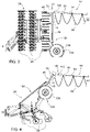
- Das erfindungsgemäße Stromversorgungssystem wird im Folgenden anhand der beigefügten Zeichnungen näher erläutert. Dabei sind hinsichtlich ihrer Funktion übereinstimmende bzw. vergleichbare Komponenten mit denselben Bezugszeichen gekennzeichnet. Es zeigen:
- Fig. 1
- eine mit einer beispielhaften Ausführungsform des erfindungsgemäßen Stromversorgungssystems ausgestattete Fahrzeugflotte,
- Fig. 2
- eine Aufsicht auf die Fahrzeugflotte für den Fall der Durchführung eines Wendemanövers,
- Fig. 3
- ein Flottenfahrzeug, umfassend ein landwirtschaftliches Heckanbaugerät mit einer in einer angehobenen Arbeitsposition befindlichen Hilfsachse, und
- Fig. 4
- das in
Fig. 3 wiedergegebene landwirtschaftliche Heckanbaugerät, bei dem die Hilfsachse in eine abgesenkte Transportposition verbracht ist. -
Fig. 1 zeigt eine mit einer beispielhaften Ausführungsform des erfindungsgemäßen Stromversorgungssystems ausgestattete Fahrzeugflotte. - Der Übersichtlichkeit halber ist in
Fig. 1 von der Fahrzeugflotte 10 lediglich ein vorausfahrendes erstes Flottenfahrzeug 12 und ein nachfolgendes zweites Flottenfahrzeug 14 dargestellt, tatsächlich lässt sich das Stromversorgungssystem 16 aber auf eine beliebige Anzahl weiterer vorausfahrender bzw. nachfolgender Flottenfahrzeuge ausdehnen, wobei diese miteinander zu einem elektrisch betriebenen Flottenverband vernetzt sind. - Jedes der Flottenfahrzeuge 12, 14 umfasst ein kabelgebunden betreibbares Zugfahrzeug 18, 20 sowie ein daran angebrachtes landwirtschaftliches Heckanbaugerät 22, 24 mit Arbeitswerkzeugen 26, 28 zur Ausführung einer zugehörigen Bodenbearbeitungsfunktion. Im vorliegenden Fall sind die Flottenfahrzeuge 12, 14 als autonom fahrende landwirtschaftliche Traktoren 30, 32 ausgebildet, an denen heckseitig ein Grubber mit einer nachfolgenden Reihensäeinheit angebracht ist.
- Des Weiteren ist dem Zugfahrzeug 18, 20 ein Basismast 34, 36 und dem landwirtschaftlichen Heckanbaugerät 22, 24 ein Zusatzmast 38, 40 zugeordnet. Der Zusatzmast 38, 40 ist jeweils den Arbeitswerkzeugen 26, 28 des landwirtschaftlichen Heckanbaugeräts 22, 24 in Vorwärtsfahrtrichtung 42 des Flottenfahrzeugs 12, 14 gesehen nachgelagert. Über den Basismast 36 des zweiten Flottenfahrzeugs 14 ist eine Kabelverbindung 44 mit einer an dem Zusatzmast 38 des ersten Flottenfahrzeugs 12 angeordneten Stromversorgungsschnittstelle 46 hergestellt.
- Wie ebenfalls in
Fig. 1 zu erkennen ist, ist an dem Zusatzmast 40 des zweiten Flottenfahrzeugs 14 eine weitere Stromversorgungsschnittstelle 48 angeordnet. Diese dient der Herstellung einer weiteren Kabelverbindung 50 mit einem nicht dargestellten dritten Flottenfahrzeug 52, das dem zweiten Flottenfahrzeug 14 nachfolgt. - Der Basismast 34, 36 bzw. der Zusatzmast 38, 40 weist die Gestalt einer in Richtung einer Hochachse des Zugfahrzeugs 18, 20 bzw. des landwirtschaftlichen Heckanbaugeräts 22, 24 verlaufenden Haltestruktur auf. Die Haltestruktur besteht beispielsweise aus Stahl, einer hochfesten Aluminiumlegierung und/oder faserverstärktem Kunststoff.
- In einem oberen Endbereich 54, 56 des Basismasts 34, 36 befindet sich eine drehbare Wickeltrommel 58, 60 zur Lagerung eines Trägerseils 62, 64, wobei das Trägerseil 62, 64 der Führung eines an der Stromversorgungsschnittstelle 46, 48 des Flottenfahrzeugs 12, 14 anschließbaren Energie- und/oder Datenübertragungskabels 66, 68 dient. Bei der Stromversorgungsschnittstelle 46, 48 handelt es sich um eine elektrische Steckvorrichtung 70, 72, wohingegen sich das Trägerseil 62, 64 in einem oberen Endbereich 74, 76 des Zusatzmasts 38, 40 mittels einer lösbaren Kupplungseinrichtung 78, 80 anbringen lässt.
- Die dem Basismast 34, 36 zugeordnete Wickeltrommel 58, 60 weist einen Trommelkörper 82, 84 zur Aufnahme des Trägerseils 62, 64 auf. Der Trommelkörper 82, 84 lässt sich durch Ansteuerung eines als elektrischer Getriebemotor 86, 88 ausgebildeten motorischen Antriebs zum Auf- und Abspulen des Trägerseils 62, 64 in Drehung versetzen. Eine mit dem elektrischen Getriebemotor 86, 88 zusammenwirkende Einrichtung 90, 92 zur Drehmomentsteuerung ermöglicht die Einhaltung einer vorgegebenen Seilzugspannung, sodass ein übermäßiges Durchhängen des Trägerseils 62, 64 zwischen den Masten 34, 36, 38, 40 der Flottenfahrzeuge 12, 14 vermieden werden kann. Bezüglich der weiteren Einzelheiten sei auf das in
DE 10 2017 217 481 A1 beschriebene Stromversorgungssystem hingewiesen. Das Trägerseil 62, 64 besteht aus einer Vielzahl von Metalldrähten und/oder hochfesten Kunststofffasern. -
Fig. 2 zeigt eine Aufsicht auf die Fahrzeugflotte 10 für den Fall der Durchführung eines Wendemanövers, wobei neben den beiden Flottenfahrzeugen 12, 14 zusätzlich ein die Fahrzeugflotte 10 anführendes Leitfahrzeug 94 abgebildet ist. Das Leitfahrzeug 94 weist einen mit den nachfolgenden Flottenfahrzeugen 12, 14 vergleichbaren Aufbau mit einem kabelgebunden betreibbaren Zugfahrzeug 96 in Gestalt eines autonom fahrenden landwirtschaftlichen Traktors 98 sowie einem daran angebrachten landwirtschaftlichen Heckanbaugerät 100 mit Arbeitswerkzeugen 102 zur Ausführung einer zugehörigen Bodenbearbeitungsfunktion auf. Letzteres ist auch hier durch einen Grubber mit einer nachfolgenden Reihensäeinheit beispielhaft veranschaulicht. - An dem landwirtschaftlichen Heckanbaugerät 100 des Leitfahrzeugs 94 ist ein mit den nachfolgenden Flottenfahrzeugen 12, 14 korrespondierender Zusatzmast 104 zur Herstellung einer entsprechenden Kabelverbindung 106 angebracht, wozu der Zusatzmast 104 ebenfalls eine Stromversorgungsschnittstelle 108 in Gestalt einer elektrischen Steckvorrichtung 110 aufweist, an der ein vom Basismast 34 des ersten Flottenfahrzeugs 12 ausgehendes und mittels eines zugehörigen Trägerseils 112 geführtes Energie- und/oder Datenübertragungskabel 114 angeschlossen ist. Das Trägerseil 112 ist in einem oberen Endbereich 116 des Zusatzmasts 104 mittels einer lösbaren Kupplungseinrichtung 118 angebracht.
- Anstelle eines Basismasts sind an dem Leitfahrzeug 94 Mittel zur Herstellung einer Stromversorgungsverbindung 120 mit einer stationären Energieversorgungseinrichtung 122 vorgesehen, die sich in Gestalt einer Umspannstation 124 am Rande des zu bearbeitenden Felds 126 befindet. Bei den Mitteln zur Herstellung der Stromversorgungsverbindung 120 handelt es sich um eine Kabeltrommel 128 mit einem aktiv gesteuerten Kabelführungsarm 130, wie sie aus der
DE 10 2018 212 150 A1 bekannt ist. - Während des Bearbeitungsvorgangs bewegen sich die einzelnen Flottenfahrzeuge 12, 14 gemeinsam mit dem Leitfahrzeug 94 im Flottenverband hintereinander über das zu bearbeitende Feld 126. Erreicht das vorderste Flottenfahrzeug bzw. Leitfahrzeug 94 das Vorgewende im Feldrandbereich 132, so müssen sämtliche nachfolgenden Flottenfahrzeuge 12, 14 ebenfalls nacheinander wenden, um in den nächsten zu bearbeitenden Feldabschnitt einzubiegen. Da jedes der auf das Leitfahrzeug 94 folgenden Flottenfahrzeuge 12, 14 am nachgelagerten Zusatzmast 38, 40, 104 des Vorderfahrzeugs elektrisch angebunden ist, sind Kollisionen mit den zwischen den Flottenfahrzeugen 12, 14 einschließlich des Leitfahrzeugs 94 verlaufenden Kabelverbindungen 44, 50 während der Durchführung des Wendemanövers ausgeschlossen. Auf diese Weise ist stets eine koordinierte Leitungsführung gewährleistet.
-
Fig. 3 bzw. 4 zeigt ein einzelnes der Flottenfahrzeuge 12, 14, stellvertretend das erste Flottenfahrzeug 12. Das zugehörige landwirtschaftliche Heckanbaugerät 22 weist eine zwischen einer abgesenkten Transportposition (sieheFig. 3 ) und einer angehobenen Arbeitsposition (sieheFig. 4 ) verstellbare Hilfsachse 134 mit wenigstens einem Stützrad 136 auf, wobei der Zusatzmast 38 derart mit einem Verstellmechanismus 138 der Hilfsachse 134 bewegungsgekoppelt ist, dass dieser mitsamt der Hilfsachse 134 abgesenkt bzw. angehoben wird. Dies lässt in der Arbeitsposition einen größeren Seildurchhang zu, was während der Feldbearbeitung die Zugkraft im Trägerseil 62 verringert und damit die Belastung der Masten bzw. der von diesen umfassten Haltestrukturen. In der Transportstellung hingegen führt die Absenkung des Zusatzmasts 38 zu einer entsprechenden Verringerung der Gesamthöhe des Flottenfahrzeugs 12 im Bereich des landwirtschaftlichen Heckanbaugeräts 22, was beim Transport auf einem Tieflader oder beim Befahren von Straßen im Hinblick auf mögliche Höhenbegrenzungen entlang des Transportwegs von Vorteil ist. Letztere können sich beispielsweise aufgrund von Brücken, Tunnels, Oberlandleitungen oder dergleichen ergeben. - Der Verstellmechanismus 138 ist in Gestalt einer Parallelogrammführung ausgebildet, sodass der Zusatzmast 38 beim Absenken bzw. Anheben der Hilfsachse 134 seine räumliche Orientierung beibehält.
- Des Weiteren ist an dem Zusatzmast 38 eine Führungsanordnung 140 vorgesehen, die das an dem Zusatzmast 38 angebrachte Trägerseil 62 in einem vorgegebenen Abstand gegenüber baulichen Strukturen des Flottenfahrzeugs 12, insbesondere des landwirtschaftlichen Heckanbaugeräts 22 hält. Bei der Führungsanordnung 140 handelt es sich um eine im oberen Endbereich 74 des Zusatzmasts 38 angeordnete Schleppkette 142, an deren freien Ende das Trägerseil 62 mittels der lösbaren Kupplungseinrichtung 78 angebracht ist. Die Glieder bzw. Gelenke der Schleppkette 142 sind derart ausgelegt, dass lediglich eine Verschwenkung in einer gegenüber dem Zusatzmast 38 senkrecht verlaufenden Horizontalebene möglich ist, wobei ein bestimmter Mindestradius nicht unterschritten wird, der derart bemessen ist, dass das Trägerseil 62 sicher bzw. kollisionsfrei um die baulichen Strukturen des Flottenfahrzeugs 12 herumgelenkt wird.
Claims (7)
- Stromversorgungssystem eines Flottenfahrzeugs (14), umfassend ein kabelgebunden betreibbares Zugfahrzeug (20) sowie ein daran angebrachtes landwirtschaftliches Heckanbaugerät (24) mit Arbeitswerkzeugen (28) zur Ausführung einer Bodenbearbeitungsfunktion, dadurch gekennzeichnet, dass dem Zugfahrzeug (20) ein Basismast (36) zur Herstellung einer Kabelverbindung (44) mit einer Stromversorgungsschnittstelle (46) eines vorausfahrenden Flottenfahrzeugs (12) und dem landwirtschaftlichen Heckanbaugerät (24) ein Zusatzmast (40) mit einer weiteren Stromversorgungsschnittstelle (48) zur Herstellung einer weiteren Kabelverbindung (50) mit einem nachfolgenden Flottenfahrzeug (52) zugeordnet ist, wobei der Zusatzmast (40) den Arbeitswerkzeugen (28) des landwirtschaftlichen Heckanbaugeräts (24) in Vorwärtsfahrtrichtung (42) des Flottenfahrzeugs (14) gesehen nachgelagert ist.
- Stromversorgungssystem nach Anspruch 1, dadurch gekennzeichnet, dass sich in einem oberen Endbereich (56) des Basismasts (36) eine drehbare Wickeltrommel (60) zur Lagerung eines Trägerseils (62) befindet, wobei das Trägerseil (62) der Führung eines an der Stromversorgungsschnittstelle (46) des vorausfahrenden Flottenfahrzeugs (12) anschließbaren Energie- und/oder Datenübertragungskabels (66) dient.
- Stromversorgungssystem nach Anspruch 2, dadurch gekennzeichnet, dass die Wickeltrommel (60) einen Trommelkörper (84) zur Aufnahme des Trägerseils (62) aufweist, wobei sich der Trommelkörper (84) durch Ansteuerung eines motorischen Antriebs (88) zum Auf- und Abspulen des Trägerseils (62) in Drehung versetzen lässt.
- Stromversorgungssystem nach wenigstens einem der Ansprüche 1 bis 3, dadurch gekennzeichnet, dass das landwirtschaftliche Heckanbaugerät (24) eine zwischen einer abgesenkten Transportposition und einer angehobenen Arbeitsposition verstellbare Hilfsachse (134) mit wenigstens einem Stützrad (136) aufweist, wobei der Zusatzmast (40) derart mit einem Verstellmechanismus (138) der Hilfsachse (134) bewegungsgekoppelt ist, dass dieser mitsamt der Hilfsachse (134) abgesenkt bzw. angehoben wird.
- Stromversorgungssystem nach Anspruch 4, dadurch gekennzeichnet, dass der Verstellmechanismus (138) in Gestalt einer Parallelogrammführung derart ausgebildet ist, dass der Zusatzmast (40) beim Absenken bzw. Anheben der Hilfsachse (134) seine räumliche Orientierung beibehält.
- Stromversorgungssystem nach wenigstens einem der Ansprüche 1 bis 5, dadurch gekennzeichnet, dass an dem Zusatzmast (40) eine Führungsanordnung (140) vorgesehen ist, die ein an dem Zusatzmast (40) anbringbares Trägerseil (64) in einem vorgegebenen Abstand gegenüber baulichen Strukturen des Flottenfahrzeugs (14) hält.
- Fahrzeugflotte (10) mit einer Vielzahl von mittels eines Stromversorgungssystems (16) nach wenigstens einem der Ansprüche 1 bis 6 vernetzten Flottenfahrzeugen (12, 14, 52, 94).
Applications Claiming Priority (1)
| Application Number | Priority Date | Filing Date | Title |
|---|---|---|---|
| DE102019203653.8A DE102019203653A1 (de) | 2019-03-18 | 2019-03-18 | Stromversorgungssystem für eine Fahrzeugflotte |
Publications (2)
| Publication Number | Publication Date |
|---|---|
| EP3712003A1 EP3712003A1 (de) | 2020-09-23 |
| EP3712003B1 true EP3712003B1 (de) | 2023-01-25 |
Family
ID=69810703
Family Applications (1)
| Application Number | Title | Priority Date | Filing Date |
|---|---|---|---|
| EP20162799.9A Active EP3712003B1 (de) | 2019-03-18 | 2020-03-12 | Stromversorgungssystem eines flottenfahrzeugs |
Country Status (3)
| Country | Link |
|---|---|
| US (1) | US11660919B2 (de) |
| EP (1) | EP3712003B1 (de) |
| DE (1) | DE102019203653A1 (de) |
Cited By (1)
| Publication number | Priority date | Publication date | Assignee | Title |
|---|---|---|---|---|
| WO2025262568A1 (en) * | 2024-06-17 | 2025-12-26 | Lely Patent N.V. | System for use on a farm |
Families Citing this family (7)
| Publication number | Priority date | Publication date | Assignee | Title |
|---|---|---|---|---|
| USD962998S1 (en) | 2019-03-18 | 2022-09-06 | Deere & Company | Hood for a work machine |
| DE102019211496A1 (de) * | 2019-08-01 | 2021-02-04 | Deere & Company | Landwirtschaftliches Fahrzeuggespann |
| USD939592S1 (en) | 2020-03-05 | 2021-12-28 | Deere & Company | Work machine |
| DE102020132038A1 (de) | 2020-12-02 | 2022-06-02 | Deere & Company | Bedienerschnittstelle für eine autonome Maschine |
| DE102020132059A1 (de) | 2020-12-02 | 2022-06-02 | Deere & Company | Bedienerschnittstelle für eine autonome Maschine |
| US12030354B2 (en) * | 2021-07-07 | 2024-07-09 | Ford Global Technologies, Llc | Electrified vehicle winch and winch operating method |
| GB202208761D0 (en) | 2022-06-15 | 2022-07-27 | Agco Int Gmbh | Method and control system for controlling a wired vehicle fleet |
Family Cites Families (7)
| Publication number | Priority date | Publication date | Assignee | Title |
|---|---|---|---|---|
| GB801770A (en) | 1955-12-21 | 1958-09-24 | David Rushworth | An improved method and means for supplying power to a movable carriage or tool |
| JP5791363B2 (ja) | 2011-05-10 | 2015-10-07 | 株式会社小松製作所 | 自走式ケーブル中継台車 |
| US9485900B2 (en) * | 2014-09-29 | 2016-11-08 | Deere & Company | Agricultural implement plug detection |
| DE102017217481A1 (de) * | 2017-09-29 | 2019-04-04 | Deere & Company | Stromversorgungssystem für eine Fahrzeugflotte |
| DE102018108024A1 (de) | 2018-04-05 | 2019-10-10 | Horsch Maschinen Gmbh | Autonomes landwirtschaftliches Trägerfahrzeug |
| US10650538B2 (en) * | 2018-06-27 | 2020-05-12 | Cnh Industrial Canada, Ltd. | Detecting and measuring the size of clods and other soil features from imagery |
| DE102018212150A1 (de) * | 2018-07-20 | 2020-01-23 | Deere & Company | Verfahren zur Energieversorgung eines kabelgebundenen betriebenen Feldhäckslers |
-
2019
- 2019-03-18 DE DE102019203653.8A patent/DE102019203653A1/de not_active Withdrawn
-
2020
- 2020-03-05 US US16/810,487 patent/US11660919B2/en active Active
- 2020-03-12 EP EP20162799.9A patent/EP3712003B1/de active Active
Cited By (2)
| Publication number | Priority date | Publication date | Assignee | Title |
|---|---|---|---|---|
| WO2025262568A1 (en) * | 2024-06-17 | 2025-12-26 | Lely Patent N.V. | System for use on a farm |
| NL2037965B1 (nl) * | 2024-06-17 | 2026-01-12 | Lely Patent Nv | Systeem |
Also Published As
| Publication number | Publication date |
|---|---|
| EP3712003A1 (de) | 2020-09-23 |
| US11660919B2 (en) | 2023-05-30 |
| US20200298641A1 (en) | 2020-09-24 |
| DE102019203653A1 (de) | 2020-09-24 |
Similar Documents
| Publication | Publication Date | Title |
|---|---|---|
| EP3712003B1 (de) | Stromversorgungssystem eines flottenfahrzeugs | |
| EP3597470B1 (de) | Verfahren zur energieversorgung eines kabelgebunden betriebenen feldhäckslers | |
| EP3771318B1 (de) | Landwirtschaftliches fahrzeuggespann | |
| EP2621257B1 (de) | Kombination aus einem zugfahrzeug und einem gerät | |
| EP2283719B1 (de) | Anordnung zur seitlichen verstellbaren Anbringung eines landwirtschaftlichen Arbeitsgeräts an einem Fahrzeug | |
| EP3058820B1 (de) | Verfahren zur bewegungssteuerung und/oder regelung einer landwirtschaftlichen verteilvorrichtung | |
| EP2402213B1 (de) | Anordnung zur Kontrolle der Arbeitsgerätebeleuchtung eines Arbeitsfahrzeugs | |
| DE102017110637B4 (de) | Vollautomatischer Zinkenstriegel | |
| EP3772265A1 (de) | Hackvorrichtung | |
| EP0059409A2 (de) | Kraftfahrzeug, insbesondere Ackerschlepper | |
| DD209219A5 (de) | Gleisverfahrbare gleisbaumaschine mit fuehrerstand | |
| EP4164367B1 (de) | Bodenbearbeitungsgerät für reihenkulturen | |
| EP3035794B1 (de) | Verfahren zur bewegungssteuerung und/oder regelung einer landwirtschaftlichen verteilvorrichtung | |
| DE102018123245A1 (de) | Anbaugewicht für ein landwirtschaftliches Fahrzeug | |
| DE2939987A1 (de) | Verfahren zum ausrichten von fahrbaren landwirtschaftlichen einrichtungen sowie vorrichtung zum durchfuehren des verfahrens | |
| EP0551160A1 (de) | Geräteträger zum Anbau an selbstfahrende Fahrzeuge, insbesondere zum Präparieren von Skipisten | |
| AT523297A4 (de) | Autonomer Geräteträger | |
| WO2023222478A1 (de) | Selbstfahrende arbeitsmaschine für die landwirtschaft | |
| DE19541872C2 (de) | Selbstfahrende Rübenerntemaschine | |
| DE3535683A1 (de) | Bodenbearbeitungsgeraet fuer die landwirtschaft | |
| DE2615497A1 (de) | Zugdeichselanordnung, insbesondere fuer einachsige schleppergezogene landwirtschaftliche maschinen | |
| EP4108556B1 (de) | Fahrzeug und entsprechende verwendung | |
| EP1319329B1 (de) | Selbstfahrende Arbeitsmaschine für den landwirtschaftlichen Einsatz | |
| DE2818640C2 (de) | Verfahren zum selbsttätigen Führen eines landwirtschaftlichen Motorfahrzeuges | |
| EP3311640A1 (de) | Anhängevorrichtung für ein landwirtschaftliches zugfahrzeug und ein verfahren zu deren betrieb |
Legal Events
| Date | Code | Title | Description |
|---|---|---|---|
| PUAI | Public reference made under article 153(3) epc to a published international application that has entered the european phase |
Free format text: ORIGINAL CODE: 0009012 |
|
| STAA | Information on the status of an ep patent application or granted ep patent |
Free format text: STATUS: THE APPLICATION HAS BEEN PUBLISHED |
|
| AK | Designated contracting states |
Kind code of ref document: A1 Designated state(s): AL AT BE BG CH CY CZ DE DK EE ES FI FR GB GR HR HU IE IS IT LI LT LU LV MC MK MT NL NO PL PT RO RS SE SI SK SM TR |
|
| AX | Request for extension of the european patent |
Extension state: BA ME |
|
| STAA | Information on the status of an ep patent application or granted ep patent |
Free format text: STATUS: REQUEST FOR EXAMINATION WAS MADE |
|
| 17P | Request for examination filed |
Effective date: 20210323 |
|
| RBV | Designated contracting states (corrected) |
Designated state(s): AL AT BE BG CH CY CZ DE DK EE ES FI FR GB GR HR HU IE IS IT LI LT LU LV MC MK MT NL NO PL PT RO RS SE SI SK SM TR |
|
| GRAP | Despatch of communication of intention to grant a patent |
Free format text: ORIGINAL CODE: EPIDOSNIGR1 |
|
| STAA | Information on the status of an ep patent application or granted ep patent |
Free format text: STATUS: GRANT OF PATENT IS INTENDED |
|
| INTG | Intention to grant announced |
Effective date: 20220916 |
|
| GRAS | Grant fee paid |
Free format text: ORIGINAL CODE: EPIDOSNIGR3 |
|
| GRAA | (expected) grant |
Free format text: ORIGINAL CODE: 0009210 |
|
| STAA | Information on the status of an ep patent application or granted ep patent |
Free format text: STATUS: THE PATENT HAS BEEN GRANTED |
|
| AK | Designated contracting states |
Kind code of ref document: B1 Designated state(s): AL AT BE BG CH CY CZ DE DK EE ES FI FR GB GR HR HU IE IS IT LI LT LU LV MC MK MT NL NO PL PT RO RS SE SI SK SM TR |
|
| REG | Reference to a national code |
Ref country code: GB Ref legal event code: FG4D Free format text: NOT ENGLISH |
|
| REG | Reference to a national code |
Ref country code: CH Ref legal event code: EP |
|
| REG | Reference to a national code |
Ref country code: DE Ref legal event code: R096 Ref document number: 502020002421 Country of ref document: DE |
|
| REG | Reference to a national code |
Ref country code: AT Ref legal event code: REF Ref document number: 1545691 Country of ref document: AT Kind code of ref document: T Effective date: 20230215 Ref country code: IE Ref legal event code: FG4D Free format text: LANGUAGE OF EP DOCUMENT: GERMAN |
|
| REG | Reference to a national code |
Ref country code: LT Ref legal event code: MG9D |
|
| REG | Reference to a national code |
Ref country code: NL Ref legal event code: MP Effective date: 20230125 |
|
| PG25 | Lapsed in a contracting state [announced via postgrant information from national office to epo] |
Ref country code: NL Free format text: LAPSE BECAUSE OF FAILURE TO SUBMIT A TRANSLATION OF THE DESCRIPTION OR TO PAY THE FEE WITHIN THE PRESCRIBED TIME-LIMIT Effective date: 20230125 |
|
| PG25 | Lapsed in a contracting state [announced via postgrant information from national office to epo] |
Ref country code: RS Free format text: LAPSE BECAUSE OF FAILURE TO SUBMIT A TRANSLATION OF THE DESCRIPTION OR TO PAY THE FEE WITHIN THE PRESCRIBED TIME-LIMIT Effective date: 20230125 Ref country code: PT Free format text: LAPSE BECAUSE OF FAILURE TO SUBMIT A TRANSLATION OF THE DESCRIPTION OR TO PAY THE FEE WITHIN THE PRESCRIBED TIME-LIMIT Effective date: 20230525 Ref country code: NO Free format text: LAPSE BECAUSE OF FAILURE TO SUBMIT A TRANSLATION OF THE DESCRIPTION OR TO PAY THE FEE WITHIN THE PRESCRIBED TIME-LIMIT Effective date: 20230425 Ref country code: LV Free format text: LAPSE BECAUSE OF FAILURE TO SUBMIT A TRANSLATION OF THE DESCRIPTION OR TO PAY THE FEE WITHIN THE PRESCRIBED TIME-LIMIT Effective date: 20230125 Ref country code: LT Free format text: LAPSE BECAUSE OF FAILURE TO SUBMIT A TRANSLATION OF THE DESCRIPTION OR TO PAY THE FEE WITHIN THE PRESCRIBED TIME-LIMIT Effective date: 20230125 Ref country code: HR Free format text: LAPSE BECAUSE OF FAILURE TO SUBMIT A TRANSLATION OF THE DESCRIPTION OR TO PAY THE FEE WITHIN THE PRESCRIBED TIME-LIMIT Effective date: 20230125 Ref country code: ES Free format text: LAPSE BECAUSE OF FAILURE TO SUBMIT A TRANSLATION OF THE DESCRIPTION OR TO PAY THE FEE WITHIN THE PRESCRIBED TIME-LIMIT Effective date: 20230125 |
|
| PG25 | Lapsed in a contracting state [announced via postgrant information from national office to epo] |
Ref country code: SE Free format text: LAPSE BECAUSE OF FAILURE TO SUBMIT A TRANSLATION OF THE DESCRIPTION OR TO PAY THE FEE WITHIN THE PRESCRIBED TIME-LIMIT Effective date: 20230125 Ref country code: PL Free format text: LAPSE BECAUSE OF FAILURE TO SUBMIT A TRANSLATION OF THE DESCRIPTION OR TO PAY THE FEE WITHIN THE PRESCRIBED TIME-LIMIT Effective date: 20230125 Ref country code: IS Free format text: LAPSE BECAUSE OF FAILURE TO SUBMIT A TRANSLATION OF THE DESCRIPTION OR TO PAY THE FEE WITHIN THE PRESCRIBED TIME-LIMIT Effective date: 20230525 Ref country code: GR Free format text: LAPSE BECAUSE OF FAILURE TO SUBMIT A TRANSLATION OF THE DESCRIPTION OR TO PAY THE FEE WITHIN THE PRESCRIBED TIME-LIMIT Effective date: 20230426 Ref country code: FI Free format text: LAPSE BECAUSE OF FAILURE TO SUBMIT A TRANSLATION OF THE DESCRIPTION OR TO PAY THE FEE WITHIN THE PRESCRIBED TIME-LIMIT Effective date: 20230125 |
|
| REG | Reference to a national code |
Ref country code: DE Ref legal event code: R097 Ref document number: 502020002421 Country of ref document: DE |
|
| PG25 | Lapsed in a contracting state [announced via postgrant information from national office to epo] |
Ref country code: SM Free format text: LAPSE BECAUSE OF FAILURE TO SUBMIT A TRANSLATION OF THE DESCRIPTION OR TO PAY THE FEE WITHIN THE PRESCRIBED TIME-LIMIT Effective date: 20230125 Ref country code: RO Free format text: LAPSE BECAUSE OF FAILURE TO SUBMIT A TRANSLATION OF THE DESCRIPTION OR TO PAY THE FEE WITHIN THE PRESCRIBED TIME-LIMIT Effective date: 20230125 Ref country code: MC Free format text: LAPSE BECAUSE OF FAILURE TO SUBMIT A TRANSLATION OF THE DESCRIPTION OR TO PAY THE FEE WITHIN THE PRESCRIBED TIME-LIMIT Effective date: 20230125 Ref country code: EE Free format text: LAPSE BECAUSE OF FAILURE TO SUBMIT A TRANSLATION OF THE DESCRIPTION OR TO PAY THE FEE WITHIN THE PRESCRIBED TIME-LIMIT Effective date: 20230125 Ref country code: DK Free format text: LAPSE BECAUSE OF FAILURE TO SUBMIT A TRANSLATION OF THE DESCRIPTION OR TO PAY THE FEE WITHIN THE PRESCRIBED TIME-LIMIT Effective date: 20230125 Ref country code: CZ Free format text: LAPSE BECAUSE OF FAILURE TO SUBMIT A TRANSLATION OF THE DESCRIPTION OR TO PAY THE FEE WITHIN THE PRESCRIBED TIME-LIMIT Effective date: 20230125 |
|
| REG | Reference to a national code |
Ref country code: CH Ref legal event code: PL |
|
| PG25 | Lapsed in a contracting state [announced via postgrant information from national office to epo] |
Ref country code: SK Free format text: LAPSE BECAUSE OF FAILURE TO SUBMIT A TRANSLATION OF THE DESCRIPTION OR TO PAY THE FEE WITHIN THE PRESCRIBED TIME-LIMIT Effective date: 20230125 |
|
| REG | Reference to a national code |
Ref country code: BE Ref legal event code: MM Effective date: 20230331 |
|
| PLBE | No opposition filed within time limit |
Free format text: ORIGINAL CODE: 0009261 |
|
| STAA | Information on the status of an ep patent application or granted ep patent |
Free format text: STATUS: NO OPPOSITION FILED WITHIN TIME LIMIT |
|
| PG25 | Lapsed in a contracting state [announced via postgrant information from national office to epo] |
Ref country code: LU Free format text: LAPSE BECAUSE OF NON-PAYMENT OF DUE FEES Effective date: 20230312 |
|
| 26N | No opposition filed |
Effective date: 20231026 |
|
| REG | Reference to a national code |
Ref country code: IE Ref legal event code: MM4A |
|
| PG25 | Lapsed in a contracting state [announced via postgrant information from national office to epo] |
Ref country code: SI Free format text: LAPSE BECAUSE OF FAILURE TO SUBMIT A TRANSLATION OF THE DESCRIPTION OR TO PAY THE FEE WITHIN THE PRESCRIBED TIME-LIMIT Effective date: 20230125 Ref country code: LI Free format text: LAPSE BECAUSE OF NON-PAYMENT OF DUE FEES Effective date: 20230331 Ref country code: IE Free format text: LAPSE BECAUSE OF NON-PAYMENT OF DUE FEES Effective date: 20230312 Ref country code: CH Free format text: LAPSE BECAUSE OF NON-PAYMENT OF DUE FEES Effective date: 20230331 |
|
| PG25 | Lapsed in a contracting state [announced via postgrant information from national office to epo] |
Ref country code: BE Free format text: LAPSE BECAUSE OF NON-PAYMENT OF DUE FEES Effective date: 20230331 |
|
| PG25 | Lapsed in a contracting state [announced via postgrant information from national office to epo] |
Ref country code: BG Free format text: LAPSE BECAUSE OF FAILURE TO SUBMIT A TRANSLATION OF THE DESCRIPTION OR TO PAY THE FEE WITHIN THE PRESCRIBED TIME-LIMIT Effective date: 20230125 |
|
| GBPC | Gb: european patent ceased through non-payment of renewal fee |
Effective date: 20240312 |
|
| PG25 | Lapsed in a contracting state [announced via postgrant information from national office to epo] |
Ref country code: BG Free format text: LAPSE BECAUSE OF FAILURE TO SUBMIT A TRANSLATION OF THE DESCRIPTION OR TO PAY THE FEE WITHIN THE PRESCRIBED TIME-LIMIT Effective date: 20230125 |
|
| PG25 | Lapsed in a contracting state [announced via postgrant information from national office to epo] |
Ref country code: GB Free format text: LAPSE BECAUSE OF NON-PAYMENT OF DUE FEES Effective date: 20240312 |
|
| PG25 | Lapsed in a contracting state [announced via postgrant information from national office to epo] |
Ref country code: GB Free format text: LAPSE BECAUSE OF NON-PAYMENT OF DUE FEES Effective date: 20240312 |
|
| PGFP | Annual fee paid to national office [announced via postgrant information from national office to epo] |
Ref country code: AT Payment date: 20250417 Year of fee payment: 5 |
|
| PG25 | Lapsed in a contracting state [announced via postgrant information from national office to epo] |
Ref country code: CY Free format text: LAPSE BECAUSE OF FAILURE TO SUBMIT A TRANSLATION OF THE DESCRIPTION OR TO PAY THE FEE WITHIN THE PRESCRIBED TIME-LIMIT; INVALID AB INITIO Effective date: 20200312 |
|
| PG25 | Lapsed in a contracting state [announced via postgrant information from national office to epo] |
Ref country code: HU Free format text: LAPSE BECAUSE OF FAILURE TO SUBMIT A TRANSLATION OF THE DESCRIPTION OR TO PAY THE FEE WITHIN THE PRESCRIBED TIME-LIMIT; INVALID AB INITIO Effective date: 20200312 |
|
| PG25 | Lapsed in a contracting state [announced via postgrant information from national office to epo] |
Ref country code: TR Free format text: LAPSE BECAUSE OF FAILURE TO SUBMIT A TRANSLATION OF THE DESCRIPTION OR TO PAY THE FEE WITHIN THE PRESCRIBED TIME-LIMIT Effective date: 20230125 |
|
| PGFP | Annual fee paid to national office [announced via postgrant information from national office to epo] |
Ref country code: DE Payment date: 20260219 Year of fee payment: 7 |
|
| PGFP | Annual fee paid to national office [announced via postgrant information from national office to epo] |
Ref country code: IT Payment date: 20260319 Year of fee payment: 7 |
|
| PGFP | Annual fee paid to national office [announced via postgrant information from national office to epo] |
Ref country code: FR Payment date: 20260325 Year of fee payment: 7 |