EP3711705A1 - Method of improving ductility of needle for root canal treatment devices and method of manufacturing needle for root canal treatment devices including method of improving ductility of needle for root canal treatment devices - Google Patents
Method of improving ductility of needle for root canal treatment devices and method of manufacturing needle for root canal treatment devices including method of improving ductility of needle for root canal treatment devices Download PDFInfo
- Publication number
- EP3711705A1 EP3711705A1 EP19193405.8A EP19193405A EP3711705A1 EP 3711705 A1 EP3711705 A1 EP 3711705A1 EP 19193405 A EP19193405 A EP 19193405A EP 3711705 A1 EP3711705 A1 EP 3711705A1
- Authority
- EP
- European Patent Office
- Prior art keywords
- needle body
- needle
- heat
- manufacturing
- root canal
- Prior art date
- Legal status (The legal status is an assumption and is not a legal conclusion. Google has not performed a legal analysis and makes no representation as to the accuracy of the status listed.)
- Granted
Links
- 238000000034 method Methods 0.000 title claims abstract description 52
- 210000004262 dental pulp cavity Anatomy 0.000 title claims abstract description 43
- 238000004519 manufacturing process Methods 0.000 title claims abstract description 37
- 238000001816 cooling Methods 0.000 claims abstract description 19
- 238000012856 packing Methods 0.000 claims abstract description 16
- 239000002184 metal Substances 0.000 claims abstract description 11
- 229910052751 metal Inorganic materials 0.000 claims abstract description 11
- 229910045601 alloy Inorganic materials 0.000 claims abstract description 8
- 239000000956 alloy Substances 0.000 claims abstract description 8
- 239000011261 inert gas Substances 0.000 claims abstract description 7
- BQCADISMDOOEFD-UHFFFAOYSA-N Silver Chemical compound [Ag] BQCADISMDOOEFD-UHFFFAOYSA-N 0.000 claims description 20
- 239000004332 silver Substances 0.000 claims description 20
- 229910052709 silver Inorganic materials 0.000 claims description 19
- 230000008569 process Effects 0.000 claims description 18
- 239000010949 copper Substances 0.000 claims description 17
- XKRFYHLGVUSROY-UHFFFAOYSA-N Argon Chemical compound [Ar] XKRFYHLGVUSROY-UHFFFAOYSA-N 0.000 claims description 16
- 239000010931 gold Substances 0.000 claims description 12
- 229910052786 argon Inorganic materials 0.000 claims description 8
- RYGMFSIKBFXOCR-UHFFFAOYSA-N Copper Chemical compound [Cu] RYGMFSIKBFXOCR-UHFFFAOYSA-N 0.000 claims description 7
- 229910000881 Cu alloy Inorganic materials 0.000 claims description 7
- 229910052802 copper Inorganic materials 0.000 claims description 7
- PCHJSUWPFVWCPO-UHFFFAOYSA-N gold Chemical compound [Au] PCHJSUWPFVWCPO-UHFFFAOYSA-N 0.000 claims description 7
- 229910052737 gold Inorganic materials 0.000 claims description 7
- 238000005406 washing Methods 0.000 claims description 5
- 238000010438 heat treatment Methods 0.000 description 16
- 239000000463 material Substances 0.000 description 14
- IJGRMHOSHXDMSA-UHFFFAOYSA-N Atomic nitrogen Chemical compound N#N IJGRMHOSHXDMSA-UHFFFAOYSA-N 0.000 description 6
- 210000003074 dental pulp Anatomy 0.000 description 4
- 239000007789 gas Substances 0.000 description 4
- 239000011248 coating agent Substances 0.000 description 3
- 238000000576 coating method Methods 0.000 description 3
- 238000010586 diagram Methods 0.000 description 3
- 239000012535 impurity Substances 0.000 description 3
- 229910052757 nitrogen Inorganic materials 0.000 description 3
- 239000000899 Gutta-Percha Substances 0.000 description 2
- 240000000342 Palaquium gutta Species 0.000 description 2
- 230000008859 change Effects 0.000 description 2
- 229920000588 gutta-percha Polymers 0.000 description 2
- 229910001316 Ag alloy Inorganic materials 0.000 description 1
- LFQSCWFLJHTTHZ-UHFFFAOYSA-N Ethanol Chemical compound CCO LFQSCWFLJHTTHZ-UHFFFAOYSA-N 0.000 description 1
- 238000007792 addition Methods 0.000 description 1
- 238000006243 chemical reaction Methods 0.000 description 1
- 238000004140 cleaning Methods 0.000 description 1
- 230000008878 coupling Effects 0.000 description 1
- 238000010168 coupling process Methods 0.000 description 1
- 238000005859 coupling reaction Methods 0.000 description 1
- 230000007423 decrease Effects 0.000 description 1
- 208000002925 dental caries Diseases 0.000 description 1
- 238000005242 forging Methods 0.000 description 1
- 239000007788 liquid Substances 0.000 description 1
- 238000002844 melting Methods 0.000 description 1
- 230000008018 melting Effects 0.000 description 1
- 239000007769 metal material Substances 0.000 description 1
- 238000012986 modification Methods 0.000 description 1
- 230000004048 modification Effects 0.000 description 1
- 239000000025 natural resin Substances 0.000 description 1
- 210000000944 nerve tissue Anatomy 0.000 description 1
- 230000002035 prolonged effect Effects 0.000 description 1
- 238000007493 shaping process Methods 0.000 description 1
- 239000002210 silicon-based material Substances 0.000 description 1
- 239000007787 solid Substances 0.000 description 1
- 238000006467 substitution reaction Methods 0.000 description 1
- XLYOFNOQVPJJNP-UHFFFAOYSA-N water Substances O XLYOFNOQVPJJNP-UHFFFAOYSA-N 0.000 description 1
Images


Classifications
-
- C—CHEMISTRY; METALLURGY
- C21—METALLURGY OF IRON
- C21D—MODIFYING THE PHYSICAL STRUCTURE OF FERROUS METALS; GENERAL DEVICES FOR HEAT TREATMENT OF FERROUS OR NON-FERROUS METALS OR ALLOYS; MAKING METAL MALLEABLE, e.g. BY DECARBURISATION OR TEMPERING
- C21D9/00—Heat treatment, e.g. annealing, hardening, quenching or tempering, adapted for particular articles; Furnaces therefor
- C21D9/26—Heat treatment, e.g. annealing, hardening, quenching or tempering, adapted for particular articles; Furnaces therefor for needles; for teeth for card-clothing
-
- A—HUMAN NECESSITIES
- A61—MEDICAL OR VETERINARY SCIENCE; HYGIENE
- A61C—DENTISTRY; APPARATUS OR METHODS FOR ORAL OR DENTAL HYGIENE
- A61C5/00—Filling or capping teeth
- A61C5/40—Implements for surgical treatment of the roots or nerves of the teeth; Nerve needles; Methods or instruments for medication of the roots
- A61C5/46—Nerve extractors, e.g. needles; Means for removing broken parts of endodontic instruments
-
- A—HUMAN NECESSITIES
- A61—MEDICAL OR VETERINARY SCIENCE; HYGIENE
- A61C—DENTISTRY; APPARATUS OR METHODS FOR ORAL OR DENTAL HYGIENE
- A61C5/00—Filling or capping teeth
- A61C5/50—Implements for filling root canals; Methods or instruments for medication of tooth nerve channels
-
- A—HUMAN NECESSITIES
- A61—MEDICAL OR VETERINARY SCIENCE; HYGIENE
- A61L—METHODS OR APPARATUS FOR STERILISING MATERIALS OR OBJECTS IN GENERAL; DISINFECTION, STERILISATION OR DEODORISATION OF AIR; CHEMICAL ASPECTS OF BANDAGES, DRESSINGS, ABSORBENT PADS OR SURGICAL ARTICLES; MATERIALS FOR BANDAGES, DRESSINGS, ABSORBENT PADS OR SURGICAL ARTICLES
- A61L31/00—Materials for other surgical articles, e.g. stents, stent-grafts, shunts, surgical drapes, guide wires, materials for adhesion prevention, occluding devices, surgical gloves, tissue fixation devices
- A61L31/02—Inorganic materials
- A61L31/022—Metals or alloys
-
- B—PERFORMING OPERATIONS; TRANSPORTING
- B21—MECHANICAL METAL-WORKING WITHOUT ESSENTIALLY REMOVING MATERIAL; PUNCHING METAL
- B21G—MAKING NEEDLES, PINS OR NAILS OF METAL
- B21G1/00—Making needles used for performing operations
- B21G1/006—Special treatments of pins or needles, e.g. annealing, straightening
-
- B—PERFORMING OPERATIONS; TRANSPORTING
- B21—MECHANICAL METAL-WORKING WITHOUT ESSENTIALLY REMOVING MATERIAL; PUNCHING METAL
- B21G—MAKING NEEDLES, PINS OR NAILS OF METAL
- B21G1/00—Making needles used for performing operations
- B21G1/08—Making needles used for performing operations of hollow needles or needles with hollow end, e.g. hypodermic needles, larding-needles
-
- B—PERFORMING OPERATIONS; TRANSPORTING
- B23—MACHINE TOOLS; METAL-WORKING NOT OTHERWISE PROVIDED FOR
- B23P—METAL-WORKING NOT OTHERWISE PROVIDED FOR; COMBINED OPERATIONS; UNIVERSAL MACHINE TOOLS
- B23P15/00—Making specific metal objects by operations not covered by a single other subclass or a group in this subclass
-
- B—PERFORMING OPERATIONS; TRANSPORTING
- B32—LAYERED PRODUCTS
- B32B—LAYERED PRODUCTS, i.e. PRODUCTS BUILT-UP OF STRATA OF FLAT OR NON-FLAT, e.g. CELLULAR OR HONEYCOMB, FORM
- B32B15/00—Layered products comprising a layer of metal
- B32B15/01—Layered products comprising a layer of metal all layers being exclusively metallic
- B32B15/018—Layered products comprising a layer of metal all layers being exclusively metallic one layer being formed of a noble metal or a noble metal alloy
-
- C—CHEMISTRY; METALLURGY
- C22—METALLURGY; FERROUS OR NON-FERROUS ALLOYS; TREATMENT OF ALLOYS OR NON-FERROUS METALS
- C22C—ALLOYS
- C22C5/00—Alloys based on noble metals
- C22C5/06—Alloys based on silver
-
- C—CHEMISTRY; METALLURGY
- C22—METALLURGY; FERROUS OR NON-FERROUS ALLOYS; TREATMENT OF ALLOYS OR NON-FERROUS METALS
- C22C—ALLOYS
- C22C5/00—Alloys based on noble metals
- C22C5/06—Alloys based on silver
- C22C5/08—Alloys based on silver with copper as the next major constituent
-
- C—CHEMISTRY; METALLURGY
- C22—METALLURGY; FERROUS OR NON-FERROUS ALLOYS; TREATMENT OF ALLOYS OR NON-FERROUS METALS
- C22C—ALLOYS
- C22C9/00—Alloys based on copper
-
- C—CHEMISTRY; METALLURGY
- C22—METALLURGY; FERROUS OR NON-FERROUS ALLOYS; TREATMENT OF ALLOYS OR NON-FERROUS METALS
- C22F—CHANGING THE PHYSICAL STRUCTURE OF NON-FERROUS METALS AND NON-FERROUS ALLOYS
- C22F1/00—Changing the physical structure of non-ferrous metals or alloys by heat treatment or by hot or cold working
- C22F1/08—Changing the physical structure of non-ferrous metals or alloys by heat treatment or by hot or cold working of copper or alloys based thereon
-
- C—CHEMISTRY; METALLURGY
- C22—METALLURGY; FERROUS OR NON-FERROUS ALLOYS; TREATMENT OF ALLOYS OR NON-FERROUS METALS
- C22F—CHANGING THE PHYSICAL STRUCTURE OF NON-FERROUS METALS AND NON-FERROUS ALLOYS
- C22F1/00—Changing the physical structure of non-ferrous metals or alloys by heat treatment or by hot or cold working
- C22F1/14—Changing the physical structure of non-ferrous metals or alloys by heat treatment or by hot or cold working of noble metals or alloys based thereon
-
- C—CHEMISTRY; METALLURGY
- C23—COATING METALLIC MATERIAL; COATING MATERIAL WITH METALLIC MATERIAL; CHEMICAL SURFACE TREATMENT; DIFFUSION TREATMENT OF METALLIC MATERIAL; COATING BY VACUUM EVAPORATION, BY SPUTTERING, BY ION IMPLANTATION OR BY CHEMICAL VAPOUR DEPOSITION, IN GENERAL; INHIBITING CORROSION OF METALLIC MATERIAL OR INCRUSTATION IN GENERAL
- C23C—COATING METALLIC MATERIAL; COATING MATERIAL WITH METALLIC MATERIAL; SURFACE TREATMENT OF METALLIC MATERIAL BY DIFFUSION INTO THE SURFACE, BY CHEMICAL CONVERSION OR SUBSTITUTION; COATING BY VACUUM EVAPORATION, BY SPUTTERING, BY ION IMPLANTATION OR BY CHEMICAL VAPOUR DEPOSITION, IN GENERAL
- C23C30/00—Coating with metallic material characterised only by the composition of the metallic material, i.e. not characterised by the coating process
-
- A—HUMAN NECESSITIES
- A61—MEDICAL OR VETERINARY SCIENCE; HYGIENE
- A61B—DIAGNOSIS; SURGERY; IDENTIFICATION
- A61B17/00—Surgical instruments, devices or methods, e.g. tourniquets
- A61B2017/00526—Methods of manufacturing
-
- A—HUMAN NECESSITIES
- A61—MEDICAL OR VETERINARY SCIENCE; HYGIENE
- A61C—DENTISTRY; APPARATUS OR METHODS FOR ORAL OR DENTAL HYGIENE
- A61C5/00—Filling or capping teeth
- A61C5/50—Implements for filling root canals; Methods or instruments for medication of tooth nerve channels
- A61C5/55—Implements for filling root canals; Methods or instruments for medication of tooth nerve channels with heating means, e.g. for heating gutta percha
Landscapes
- Chemical & Material Sciences (AREA)
- Health & Medical Sciences (AREA)
- Engineering & Computer Science (AREA)
- Mechanical Engineering (AREA)
- Organic Chemistry (AREA)
- Metallurgy (AREA)
- Materials Engineering (AREA)
- Public Health (AREA)
- General Health & Medical Sciences (AREA)
- Animal Behavior & Ethology (AREA)
- Life Sciences & Earth Sciences (AREA)
- Epidemiology (AREA)
- Veterinary Medicine (AREA)
- Dentistry (AREA)
- Oral & Maxillofacial Surgery (AREA)
- Surgery (AREA)
- Physics & Mathematics (AREA)
- Thermal Sciences (AREA)
- Crystallography & Structural Chemistry (AREA)
- Biomedical Technology (AREA)
- Neurosurgery (AREA)
- Nuclear Medicine, Radiotherapy & Molecular Imaging (AREA)
- Neurology (AREA)
- Inorganic Chemistry (AREA)
- Heart & Thoracic Surgery (AREA)
- Vascular Medicine (AREA)
- Chemical Kinetics & Catalysis (AREA)
- Dental Tools And Instruments Or Auxiliary Dental Instruments (AREA)
Abstract
Description
- This application claims priority to Korean Patent Application No.
10-2019-0032901, filed on March 22, 2019 - The present disclosure relates to a method of improving the ductility of a needle for root canal treatment devices and a method of manufacturing a needle for root canal treatment devices including the method of improving the ductility of a needle for root canal treatment devices. More specifically, according to the present disclosure, a needle body having improved ductility may be manufactured through a heat treatment process and a cooling process, and a needle capable of being bent in a desired direction and angle and capable of being repeatedly bent and unfolded may be provided.
- In general, when dental pulp, which is the nerve tissue of a tooth, is damaged by severe dental caries or tooth breakage, root canal treatment (endodontic treatment) is performed to restore tooth function. In root canal treatment, damaged dental pulp is removed, and a space formed by removing the dental pulp is filled with a filling material (gutta-percha, which is a natural resin) using a root canal treatment device.
- A root canal treatment device includes a body in which a knob is integrally formed, a hollow needle disposed on one side of the body, and a heater for melting a filling material filling the hollow needle. According to this configuration, when the hollow needle is filled with a filling material and the heater is operated, the filling material is melted and discharged from the needle to fill dental pulp.
- Meanwhile, a needle detachably attached to the body of a root canal treatment device is manufactured so that a user can bend the needle at a predetermined angle. However, since most of conventional needles are formed of a metal material having high brittleness, it is difficult to change the angle and direction of the needle once bent.
- When the needle is forcibly unfolded or bent to change the angle and direction of the needle, the needle may be easily broken due to brittleness thereof. Accordingly, when a conventional needle is used, it is difficult to determine a treatment position. In addition, since a needle in use needs to be replaced with a needle suitable for each treatment position, inconvenience may increase.
- Therefore, the present disclosure has been made in view of the above problems, and it is an object of the present disclosure to provide a method of improving the ductility of a needle for root canal treatment devices and a method of manufacturing a needle for root canal treatment devices including the method of improving the ductility of a needle for root canal treatment devices. According to the present disclosure, a needle body formed of a metal or alloy is subjected to a heat treatment process and a cooling process to improve the ductility of the needle body while maintaining the intrinsic strength thereof. Accordingly, the needle body manufactured according to the method of the present disclosure may be repeatedly bent and unfolded, which may increase the accuracy of treatment and operator convenience.
- In accordance with one aspect of the present invention, provided is a method of manufacturing a needle for root canal treatment devices including a step of heat-treating a needle body at a predetermined temperature under an inert gas atmosphere after the needle body is placed in a vacuum chamber and a step of cooling the heat-treated needle body.
- According to one embodiment, the method of manufacturing a needle for root canal treatment devices may further include, before the step of heat-treating, a step of manufacturing a hollow needle body in a desired shape using an alloy or a single metal, wherein the step of manufacturing may include a step of filling the hollow of the needle body with a packing member.
- According to one embodiment, in the step of manufacturing, the needle body may be formed of one of copper (Cu), silver (Ag), and alloys of copper (Cu) and silver (Ag).
- According to one embodiment, in the step of manufacturing, the surface of the needle body may be selectively coated with gold (Au) or silver (Ag).
- According to one embodiment, in the step of manufacturing, a deep drawing process may be used to manufacture the needle body.
- According to one embodiment, in the step of heat-treating, an internal pressure of the chamber may be adjusted to 10-3 to 1 Torr using a vacuum pump, argon (Ar) may be supplied into the chamber, and then the needle body may be heat-treated for 1 to 10 hours at a temperature of 100 to 900 °C under atmospheric pressure.
- According to one embodiment, in the step of cooling, the heat-treated needle body may be allowed to stand for 30 minutes to 5 hours to cool naturally.
- According to one embodiment, the method of manufacturing a needle for root canal treatment devices may further include, after the step of cooling, a step of separating a packing member from the needle body and washing the needle body.
- In accordance with another aspect of the present invention, provided is a method of improving the ductility of a needle for root canal treatment devices including a step of heat-treating a needle body at a predetermined temperature under an argon (Ar) atmosphere after the needle body is placed in a vacuum chamber.
- According to one embodiment, the method of improving the ductility of a needle for root canal treatment devices may further include, before the step of heat-treating, a step of manufacturing a hollow needle body in a desired shape using an alloy or a single metal, wherein the step of manufacturing may include a step of filling the hollow of the needle body with a packing member.
- According to one embodiment, in the step of manufacturing, the needle body may be formed of one of copper (Cu), silver (Ag), and alloys of copper (Cu) and silver (Ag).
- According to one embodiment, in the step of manufacturing, the surface of the needle body may be selectively coated with gold (Au) or silver (Ag).
- According to one embodiment, in the step of heat-treating, an internal pressure of the chamber may be adjusted to 10-3 to 1 Torr using a vacuum pump, argon (Ar) may be supplied into the chamber, and then the needle body may be heat-treated for 1 to 10 hours at a temperature of 100 to 900 °C under atmospheric pressure.
- According to one embodiment, the method of improving the ductility of a needle for root canal treatment devices may further include, after the step of heat-treating, a step of cooling and hardening the needle body, wherein, in the step of cooling, the heat-treated needle body may be allowed to stand for 30 minutes to 5 hours to cool naturally.
-
-
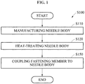
FIG. 1 is a block diagram for explaining a method of manufacturing a needle for root canal treatment devices according to one embodiment of the present disclosure. -
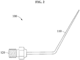
FIG. 2 is a perspective view of the needle for root canal treatment devices manufactured according to the method shown inFIG. 1 . -
FIG. 3 is a schematic side cross-sectional view of an apparatus for heat-treating the body of the needle for root canal treatment devices. -
FIG. 4 is a cross-sectional view of the needle for root canal treatment devices having a configuration in which a fastening member is coupled to a needle body. -
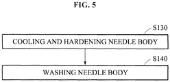
FIG. 5 is a block diagram for explaining additional steps included in the method of manufacturing a needle for root canal treatment devices according to one embodiment of the present disclosure shown inFIG. 1 . - Hereinafter, a method of manufacturing a needle for root canal treatment devices according to the present disclosure will be described with reference to the accompanying drawings. Here, the same reference numerals are used for the same components, and repeated description and detailed description of known functions and configurations that may obscure the gist of the present disclosure are omitted. These embodiments are provided to more fully describe the present disclosure to those skilled in the art. Accordingly, the shapes and sizes of the elements in the drawings can be exaggerated for clarity.
-
FIG. 1 is a block diagram for explaining a method of manufacturing a needle for root canal treatment devices according to one embodiment of the present disclosure,FIG. 2 is a perspective view of the needle for root canal treatment devices manufactured according to the method shown inFIG. 1 ,FIG. 3 is a schematic side cross-sectional view of an apparatus for heat-treating the body of the needle for root canal treatment devices, andFIG. 4 is a cross-sectional view of the needle for root canal treatment devices having a configuration in which a fastening member is coupled to a needle body. - As shown in
FIGS. 1 to 4 , method S100 of manufacturing a needle for root canal treatment devices includes step S110 of manufacturing a needle body, step S120 of heat-treating the needle body, and step S150 of coupling a fastening member to the needle body. - In step S110, a
hollow needle body 110 is manufactured to have a desired shape using an alloy or a single metal. Since a hollow is formed inside theneedle body 110, the hollow may be filled with gutta-percha, which is a root canal treatment material. - The
needle body 110 may be formed so that, when a solid root canal treatment material is heated by a heater provided in the body of the root canal treatment device, the melted root canal treatment material having a low viscosity is injected into theneedle body 110. For example, theneedle body 110 may have a straight shape, a stepped shape in which the width of a discharge portion is smaller than the width of an inlet portion, or a tapered shape in which the width of a discharge portion gradually decreases. However, the shape of theneedle body 110 is not limited to the above examples, and theneedle body 110 may be embodied in various forms. - In step S110, the
needle body 110 may be formed through a deep drawing process or a swaging process. - Deep drawing is a process in which the diameter of a product is reduced or the periphery of the inlet of the product is narrowed toward the middle of the product so that the product has a tapered shape. Swaging is a forging process, and refers to a process of longitudinally compressing a material to reduce or increase the cross-section of some or all of a material.
- Specifically, the
needle body 110 may be formed of one of copper (Cu), silver (Ag), and alloys of copper (Cu) and silver (Ag). To prevent theneedle body 110 from being oxidized due to external environments, acoating film 111 may be formed on the surface of theneedle body 110 by selectively coating the surface of theneedle body 110 with gold (Au) or silver (Ag). In this case, a material forming theneedle body 110 and a material coated on the surface of theneedle body 110 are preferably different from each other. For example, theneedle body 110 may be formed of a single metal such as copper, silver, or an alloy of copper and silver. In addition, the surface of theneedle body 110 formed of silver may be coated with silver or gold. - Step S110 may include a step of filling the hollow of the
needle body 110 with a packing member 130 (seeFIG. 4 ). This serves to prevent theneedle body 110 from being deformed when theneedle body 110 is heat-treated in step S120 to be described later. The kind of material forming the packingmember 130 is not limited, but the packingmember 130 is preferably formed of a material that is not deformed during heat treatment. For example, the packingmember 130 may be formed of an elastic silicon material. - The step of filling the
needle body 110 with thepacking member 130 is not a mandatory step and may be omitted. However, as described above, the step of filling may be additionally performed to prevent theneedle body 110 from being deformed when theneedle body 110 is heat-treated. - As shown in
FIG. 3 , in step S120, theneedle body 110 is placed in avacuum chamber 10, and heat treatment is performed at a predetermined temperature under an inert gas atmosphere. In this case, asupport 20 may be provided in thechamber 10, and theneedle body 110 is vertically placed on thesupport 20 so that the entire surface of theneedle body 110 may be uniformly heat-treated. The number of theneedle body 110 to be placed in thechamber 10 is not limited, but theneedle bodies 110 are preferably provided in thechamber 10 to improve manufacturing efficiency. - Specifically, in step S120, the internal pressure of the
chamber 10 may be adjusted to 10-3 to 1 Torr using avacuum pump 30, argon (Ar), which is an inert gas, may be supplied into thechamber 10, and then heat treatment of theneedle body 110 may be performed for 1 to 10 hours at a temperature of 100 to 900 °C under atmospheric pressure. - As shown in
FIG. 5 , method S100 according to one embodiment may further include step S130 of cooling and hardening theneedle body 110 and step S140 of washing theneedle body 110. - In step S130, the heat-treated
needle body 110 is cooled and hardened. In this case, theneedle body 110 is preferably cooled in a natural cooling manner instead of being cooled under a specific cooling atmosphere. For example, the heat-treatedneedle body 110 is preferably allowed to stand for 30 minutes to 5 hours so as to be naturally cooled. - Since the
needle body 110 is cooled in this manner after heat treatment, the ductility of theneedle body 110 may be increased without changing the intrinsic strength of a metal, so that theneedle body 110 may be bent or unfolded in a desired direction and angle. Accordingly, theneedle body 110 may be freely bent according to positions of treatment, increasing the accuracy of treatment and operator convenience. - In addition, when the heat-treated
needle body 110 is cooled, gas such as nitrogen may be supplied. That is, in step S130, the heat-treatedneedle body 110 is naturally cooled at a room temperature, and nitrogen is supplied to lower the temperature of the heat-treatedneedle body 110 for the next step. - In addition, method S100 may further include step S140 after step S130.
- In step S140, the cooled
needle body 110 is removed from thechamber 10. Then, the packingmember 130 may be separated from theneedle body 110, and theneedle body 110 may be washed to remove impurities from the surface of theneedle body 110. For example, cleaning liquid may be water or an alcohol. The cleanedneedle body 110 may be assembled into the main body of the root canal treatment device. - In addition, since, in step S120, heat treatment of the
needle body 110 is performed in the vacuum or nitrogen-filledchamber 10, the heat-treatedneedle body 110 is not contaminated and thus a separate washing process may be unnecessary. Accordingly, depending on heat treatment environments in step S120, step S140 may not be a mandatory process and thus may be omitted. - In step S150, a
fastening member 120 coupled to the main body of the root canal treatment device is coupled to one side of theneedle body 110. Accordingly, theneedle body 110 may be coupled to the main body of the root canal treatment device via thefastening member 120, and may be separated from the main body of the root canal treatment device. - A process of manufacturing a
needle 100 for root canal treatment devices will be described with reference toFIGS. 1 to 5 . - First, the
hollow needle body 110 is manufactured using an alloy or a single metal. In this case, a material forming theneedle body 110 is not particularly limited, but copper or a copper alloy having high ductility is preferably used to form theneedle body 110 of a desired shape. After the shaping process, the surface of theneedle body 110 is preferably coated with gold or silver. - After filling the packing
member 130 in the hollow of the manufacturedneedle body 110, theneedle body 110 is placed in the vertical direction on thesupport 20 provided inside thechamber 10. In this case, to remove impurities inside thechamber 10, vacuum may be formed by adjusting an internal pressure to 10-3 to 1 Torr. For this purpose, thevacuum pump 30 for adjusting pressure may be connected to one side of thechamber 10. - In addition, a
gas supply pipe 50 connected to agas supply 40 is provided at one side of thechamber 10 to supply argon (Ar), which is an inert gas, into thechamber 10. Since the inert gas is supplied from thegas supply 40, chemical reaction that may occur in theneedle body 110 may be suppressed and the internal pressure of thechamber 10 may be maintained at atmospheric pressure. - In this state, the
needle body 110 is heat-treated at a temperature of 100 to 900 °C, preferably 650 °C, for about one hour using aheating member 60 provided inside thechamber 10. In this case, when heat treatment temperature is less than 100 °C, time required for heat treatment of theneedle body 110 is prolonged, which lowers heat treatment efficiency. When heat treatment temperature exceeds 900 °C, theneedle body 110 may be melted and deformed. - After heat treatment, the
needle body 110 is allowed to stand for about 30 minutes to 5 hours to cool naturally. Then, residual heat inside thechamber 10 causes theneedle body 110 to gradually cool and harden. After natural cooling is completed, theneedle body 110 is removed from thechamber 10, and the packingmember 130 is separated from theneedle body 110. Then, when necessary, washing is performed to remove impurities adhering to the surface of theneedle body 110. - Since the
needle body 110 formed through the above described processes has high ductility while maintaining the intrinsic strength of a metal, as shown inFIG. 2 , theneedle body 110 may be bent or unfolded in a desired angle and direction. - As described above, since the ductility of the
needle body 110 manufactured by method S100 is increased by a heat treatment process and a cooling process, theneedle body 110 is not easily broken even when theneedle body 110 is repeatedly bent or unfolded. - In addition, since the
needle body 110 may be bent or unfolded in a desired direction and angle, dental treatment may be performed at a desired position, and thus the accuracy of treatment may be increased. In addition, operator convenience may be improved. - According to the present disclosure, since a needle body is manufactured through a heat treatment process and a cooling process, the ductility of the needle body can be increased, and thus the needle body is not easily broken even when the needle body is repeatedly bent or unfolded.
- In addition, since the needle body can be bent or unfolded in a desired direction and angle, dental treatment can be performed at a desired position, and thus the accuracy of treatment can be increased. Also, operator convenience can be improved.
- Although the present disclosure has been described through limited examples and figures, the present disclosure is not intended to be limited to the examples. Those skilled in the art will appreciate that various modifications, additions, and substitutions are possible, without departing from the scope and spirit of the disclosure. Therefore, the scope of protection of the present disclosure should be determined only by the appended claims.
-
- 110: NEEDLE BODY
- 111: COATING FILM
- 120: FASTENING MEMBER
- 130: PACKING MEMBER
Claims (14)
- A method of manufacturing a needle for root canal treatment devices, comprising:heat-treating a needle body at a predetermined temperature under an inert gas atmosphere after the needle body is placed in a vacuum chamber; andcooling the heat-treated needle body.
- The method according to claim 1, wherein the method further comprises, before the heat-treating, manufacturing a hollow needle body in a desired shape using an alloy or a single metal, wherein the manufacturing comprises filling a hollow of the needle body with a packing member.
- The method according to claim 2, wherein, in the manufacturing, the needle body is formed of one of copper (Cu), silver (Ag), and alloys of copper (Cu) and silver (Ag).
- The method according to claim 3, wherein, in the manufacturing, a surface of the needle body is selectively coated with gold (Au) or silver (Ag).
- The method according to claim 2, wherein, in the manufacturing, a deep drawing process is used to manufacture the needle body.
- The method according to claim 1, wherein, in the heat-treating, an internal pressure of the chamber is adjusted to 10-3 to 1 Torr using a vacuum pump, argon (Ar) is supplied into the chamber, and then the needle body is heat-treated for 1 to 10 hours at a temperature of 100 to 900 °C under atmospheric pressure.
- The method according to claim 1, wherein, in the cooling, the heat-treated needle body is allowed to stand for 30 minutes to 5 hours to cool naturally.
- The method according to claim 2, wherein the method further comprises, after the cooling, separating the packing member from the needle body and washing the needle body.
- A method of improving ductility of a needle for root canal treatment devices, comprising heat-treating a needle body at a predetermined temperature under an argon (Ar) atmosphere after the needle body is placed in a vacuum chamber.
- The method according to claim 9, wherein the method further comprises, before the heat-treating, manufacturing a hollow needle body in a desired shape using an alloy or a single metal, wherein the manufacturing comprises filling a hollow of the needle body with a packing member.
- The method according to claim 10, wherein, in the manufacturing, the needle body is formed of one of copper (Cu), silver (Ag), and alloys of copper (Cu) and silver (Ag).
- The method according to claim 11, wherein, in the manufacturing, a surface of the needle body is selectively coated with gold (Au) or silver (Ag).
- The method according to claim 9, wherein, in the heat-treating, an internal pressure of the chamber is adjusted to 10-3 to 1 Torr using a vacuum pump, argon (Ar) is supplied into the chamber, and then the needle body is heat-treated for 1 to 10 hours at a temperature of 100 to 900 °C under atmospheric pressure.
- The method according to claim 9, wherein the method further comprises, after the heat-treating, cooling and hardening the needle body, wherein, in the cooling and hardening, the heat-treated needle body is allowed to stand for 30 minutes to 5 hours to cool naturally.
Applications Claiming Priority (1)
| Application Number | Priority Date | Filing Date | Title |
|---|---|---|---|
| KR1020190032901A KR102280519B1 (en) | 2019-03-22 | 2019-03-22 | Ductility improvement method of needle for endodontic instrument and manufacturing method of needle |
Publications (2)
| Publication Number | Publication Date |
|---|---|
| EP3711705A1 true EP3711705A1 (en) | 2020-09-23 |
| EP3711705B1 EP3711705B1 (en) | 2021-05-19 |
Family
ID=67742289
Family Applications (1)
| Application Number | Title | Priority Date | Filing Date |
|---|---|---|---|
| EP19193405.8A Active EP3711705B1 (en) | 2019-03-22 | 2019-08-23 | Method of improving ductility of needle for root canal treatment devices and method of manufacturing needle for root canal treatment devices including method of improving ductility of needle for root canal treatment devices |
Country Status (7)
| Country | Link |
|---|---|
| US (1) | US11202688B2 (en) |
| EP (1) | EP3711705B1 (en) |
| JP (1) | JP6980233B2 (en) |
| KR (1) | KR102280519B1 (en) |
| CN (1) | CN111715826B (en) |
| AU (1) | AU2019208148B2 (en) |
| ES (1) | ES2887703T3 (en) |
Families Citing this family (1)
| Publication number | Priority date | Publication date | Assignee | Title |
|---|---|---|---|---|
| CN112754690A (en) * | 2021-01-18 | 2021-05-07 | 桂林市啄木鸟医疗器械有限公司 | Hot melt gutta-percha of local heating needle that generates heat for pen |
Citations (3)
| Publication number | Priority date | Publication date | Assignee | Title |
|---|---|---|---|---|
| US5814166A (en) * | 1996-11-14 | 1998-09-29 | Ethicon, Inc. | Process for heat treating and tempering surgical needles |
| US20090157116A1 (en) * | 2007-12-13 | 2009-06-18 | Ethicon, Inc. | Rapid thermal treatment for enhancing bending stiffness and yield moment of curved needles |
| WO2015104100A1 (en) * | 2014-01-09 | 2015-07-16 | Transcodent GmbH & Co. KG | Irrigation cannula and method for producing an irrigation cannula |
Family Cites Families (14)
| Publication number | Priority date | Publication date | Assignee | Title |
|---|---|---|---|---|
| JPS61243115A (en) * | 1985-04-18 | 1986-10-29 | Daido Steel Co Ltd | Vacuum heat treatment device |
| JPH0673530B2 (en) * | 1987-05-07 | 1994-09-21 | 株式会社 ニッショ− | Dental cleaning needle |
| JPH06228649A (en) * | 1993-02-02 | 1994-08-16 | Furukawa Electric Co Ltd:The | Method for annealing long size pipe |
| US5411613A (en) * | 1993-10-05 | 1995-05-02 | United States Surgical Corporation | Method of making heat treated stainless steel needles |
| CN1312055A (en) * | 2000-10-23 | 2001-09-12 | 郑玉峰 | Flexible tubular titanium-nickel apparatus without deformation and its production process |
| US6343929B1 (en) * | 2001-01-22 | 2002-02-05 | Ultradent Products, Inc. | Endodontic irrigator tips having fiber covered cannulas and related methods |
| US6422865B1 (en) * | 2001-01-22 | 2002-07-23 | Ultradent Products, Inc. | Endodontic irrigator tips having cannulas with annealed distal portions and related methods |
| US6991457B2 (en) * | 2003-05-06 | 2006-01-31 | Aseptico, Inc. | Endodontic obturator with disposable cartridge |
| KR100959639B1 (en) * | 2007-04-05 | 2010-05-26 | 이인환 | Needle unit for endodontic treatment |
| KR20100137985A (en) * | 2009-06-24 | 2010-12-31 | 조현효 | Appartus for obturating root canal |
| CA2800307C (en) * | 2010-05-10 | 2016-11-15 | Dentsply International Inc. | Endodontic rotary instruments made of shape memory alloys in their martensitic state and manufacturing methods thereof |
| US8916009B2 (en) * | 2011-05-06 | 2014-12-23 | Dentsply International Inc. | Endodontic instruments and methods of manufacturing thereof |
| US20150342714A1 (en) * | 2012-02-22 | 2015-12-03 | Transcodent GmbH & Co. KG | Dispensing Container for Dental Compound |
| KR101958196B1 (en) * | 2017-01-02 | 2019-03-14 | 이광석 | Filled injection tip for teeth treatment |
-
2019
- 2019-03-22 KR KR1020190032901A patent/KR102280519B1/en active IP Right Grant
- 2019-07-15 CN CN201910634614.8A patent/CN111715826B/en active Active
- 2019-07-22 AU AU2019208148A patent/AU2019208148B2/en active Active
- 2019-08-08 US US16/535,293 patent/US11202688B2/en active Active
- 2019-08-09 JP JP2019148108A patent/JP6980233B2/en active Active
- 2019-08-23 ES ES19193405T patent/ES2887703T3/en active Active
- 2019-08-23 EP EP19193405.8A patent/EP3711705B1/en active Active
Patent Citations (3)
| Publication number | Priority date | Publication date | Assignee | Title |
|---|---|---|---|---|
| US5814166A (en) * | 1996-11-14 | 1998-09-29 | Ethicon, Inc. | Process for heat treating and tempering surgical needles |
| US20090157116A1 (en) * | 2007-12-13 | 2009-06-18 | Ethicon, Inc. | Rapid thermal treatment for enhancing bending stiffness and yield moment of curved needles |
| WO2015104100A1 (en) * | 2014-01-09 | 2015-07-16 | Transcodent GmbH & Co. KG | Irrigation cannula and method for producing an irrigation cannula |
Also Published As
| Publication number | Publication date |
|---|---|
| AU2019208148A1 (en) | 2020-10-08 |
| ES2887703T3 (en) | 2021-12-27 |
| CN111715826B (en) | 2022-05-03 |
| KR102280519B1 (en) | 2021-07-29 |
| JP2020151451A (en) | 2020-09-24 |
| JP6980233B2 (en) | 2021-12-15 |
| CN111715826A (en) | 2020-09-29 |
| US11202688B2 (en) | 2021-12-21 |
| AU2019208148B2 (en) | 2021-05-27 |
| US20200297456A1 (en) | 2020-09-24 |
| KR20200112432A (en) | 2020-10-05 |
| EP3711705B1 (en) | 2021-05-19 |
Similar Documents
| Publication | Publication Date | Title |
|---|---|---|
| EP1978884B1 (en) | Method for localized heat treatment of orthodontic wires | |
| JP6262808B2 (en) | Shape setting of shape memory alloy dental arch | |
| US7779542B2 (en) | Method of manufacturing a dental instrument | |
| EP0465836B1 (en) | Orthodontic implement controllable of correction force | |
| US7207111B2 (en) | Method of manufacturing an endodontic instrument | |
| US20100233648A1 (en) | Endodontic instrument and method of manufacturing | |
| JP2010115534A (en) | Method for manufacturing endodontic instruments | |
| US11202688B2 (en) | Method of improving ductility of needle for root canal treatment devices and method of manufacturing needle for root canal treatment devices including method of improving ductility of needle for root canal treatment devices | |
| JP2008520354A (en) | Method for manufacturing an endodontic treatment device | |
| CN111036707A (en) | Preparation method of orthodontic wire for tooth correction | |
| WO2015006748A1 (en) | Process for producting a shape memory spiral rotary file | |
| EP0648856A1 (en) | Eyeglass frame and fabrication method | |
| JP2006249462A (en) | Method for producing electrode, and electrode | |
| WO2011118401A1 (en) | Process for production of medical instrument, and medical instrument | |
| KR20180013398A (en) | Manufacturing method of orthodontic arch wire | |
| JP2004079877A (en) | Method for manufacturing lead wire for electronic component | |
| JPH08141068A (en) | Small-diameter tube made of nickel-titanium based alloy for medical use and its production | |
| JPH07188882A (en) | Production of hydrogen occluding body |
Legal Events
| Date | Code | Title | Description |
|---|---|---|---|
| PUAI | Public reference made under article 153(3) epc to a published international application that has entered the european phase |
Free format text: ORIGINAL CODE: 0009012 |
|
| STAA | Information on the status of an ep patent application or granted ep patent |
Free format text: STATUS: REQUEST FOR EXAMINATION WAS MADE |
|
| 17P | Request for examination filed |
Effective date: 20190823 |
|
| AK | Designated contracting states |
Kind code of ref document: A1 Designated state(s): AL AT BE BG CH CY CZ DE DK EE ES FI FR GB GR HR HU IE IS IT LI LT LU LV MC MK MT NL NO PL PT RO RS SE SI SK SM TR |
|
| AX | Request for extension of the european patent |
Extension state: BA ME |
|
| RBV | Designated contracting states (corrected) |
Designated state(s): AL AT BE BG CH CY CZ DE DK EE ES FI FR GB GR HR HU IE IS IT LI LT LU LV MC MK MT NL NO PL PT RO RS SE SI SK SM TR |
|
| GRAP | Despatch of communication of intention to grant a patent |
Free format text: ORIGINAL CODE: EPIDOSNIGR1 |
|
| STAA | Information on the status of an ep patent application or granted ep patent |
Free format text: STATUS: GRANT OF PATENT IS INTENDED |
|
| INTG | Intention to grant announced |
Effective date: 20201211 |
|
| GRAS | Grant fee paid |
Free format text: ORIGINAL CODE: EPIDOSNIGR3 |
|
| GRAA | (expected) grant |
Free format text: ORIGINAL CODE: 0009210 |
|
| STAA | Information on the status of an ep patent application or granted ep patent |
Free format text: STATUS: THE PATENT HAS BEEN GRANTED |
|
| AK | Designated contracting states |
Kind code of ref document: B1 Designated state(s): AL AT BE BG CH CY CZ DE DK EE ES FI FR GB GR HR HU IE IS IT LI LT LU LV MC MK MT NL NO PL PT RO RS SE SI SK SM TR |
|
| REG | Reference to a national code |
Ref country code: GB Ref legal event code: FG4D |
|
| REG | Reference to a national code |
Ref country code: CH Ref legal event code: EP |
|
| REG | Reference to a national code |
Ref country code: DE Ref legal event code: R096 Ref document number: 602019004694 Country of ref document: DE |
|
| REG | Reference to a national code |
Ref country code: AT Ref legal event code: REF Ref document number: 1393252 Country of ref document: AT Kind code of ref document: T Effective date: 20210615 |
|
| REG | Reference to a national code |
Ref country code: IE Ref legal event code: FG4D |
|
| REG | Reference to a national code |
Ref country code: LT Ref legal event code: MG9D |
|
| REG | Reference to a national code |
Ref country code: AT Ref legal event code: MK05 Ref document number: 1393252 Country of ref document: AT Kind code of ref document: T Effective date: 20210519 |
|
| REG | Reference to a national code |
Ref country code: NL Ref legal event code: MP Effective date: 20210519 |
|
| PG25 | Lapsed in a contracting state [announced via postgrant information from national office to epo] |
Ref country code: HR Free format text: LAPSE BECAUSE OF FAILURE TO SUBMIT A TRANSLATION OF THE DESCRIPTION OR TO PAY THE FEE WITHIN THE PRESCRIBED TIME-LIMIT Effective date: 20210519 Ref country code: LT Free format text: LAPSE BECAUSE OF FAILURE TO SUBMIT A TRANSLATION OF THE DESCRIPTION OR TO PAY THE FEE WITHIN THE PRESCRIBED TIME-LIMIT Effective date: 20210519 Ref country code: FI Free format text: LAPSE BECAUSE OF FAILURE TO SUBMIT A TRANSLATION OF THE DESCRIPTION OR TO PAY THE FEE WITHIN THE PRESCRIBED TIME-LIMIT Effective date: 20210519 Ref country code: AT Free format text: LAPSE BECAUSE OF FAILURE TO SUBMIT A TRANSLATION OF THE DESCRIPTION OR TO PAY THE FEE WITHIN THE PRESCRIBED TIME-LIMIT Effective date: 20210519 Ref country code: BG Free format text: LAPSE BECAUSE OF FAILURE TO SUBMIT A TRANSLATION OF THE DESCRIPTION OR TO PAY THE FEE WITHIN THE PRESCRIBED TIME-LIMIT Effective date: 20210819 |
|
| PG25 | Lapsed in a contracting state [announced via postgrant information from national office to epo] |
Ref country code: IS Free format text: LAPSE BECAUSE OF FAILURE TO SUBMIT A TRANSLATION OF THE DESCRIPTION OR TO PAY THE FEE WITHIN THE PRESCRIBED TIME-LIMIT Effective date: 20210919 Ref country code: GR Free format text: LAPSE BECAUSE OF FAILURE TO SUBMIT A TRANSLATION OF THE DESCRIPTION OR TO PAY THE FEE WITHIN THE PRESCRIBED TIME-LIMIT Effective date: 20210820 Ref country code: LV Free format text: LAPSE BECAUSE OF FAILURE TO SUBMIT A TRANSLATION OF THE DESCRIPTION OR TO PAY THE FEE WITHIN THE PRESCRIBED TIME-LIMIT Effective date: 20210519 Ref country code: PL Free format text: LAPSE BECAUSE OF FAILURE TO SUBMIT A TRANSLATION OF THE DESCRIPTION OR TO PAY THE FEE WITHIN THE PRESCRIBED TIME-LIMIT Effective date: 20210519 Ref country code: NO Free format text: LAPSE BECAUSE OF FAILURE TO SUBMIT A TRANSLATION OF THE DESCRIPTION OR TO PAY THE FEE WITHIN THE PRESCRIBED TIME-LIMIT Effective date: 20210819 Ref country code: PT Free format text: LAPSE BECAUSE OF FAILURE TO SUBMIT A TRANSLATION OF THE DESCRIPTION OR TO PAY THE FEE WITHIN THE PRESCRIBED TIME-LIMIT Effective date: 20210920 Ref country code: RS Free format text: LAPSE BECAUSE OF FAILURE TO SUBMIT A TRANSLATION OF THE DESCRIPTION OR TO PAY THE FEE WITHIN THE PRESCRIBED TIME-LIMIT Effective date: 20210519 Ref country code: SE Free format text: LAPSE BECAUSE OF FAILURE TO SUBMIT A TRANSLATION OF THE DESCRIPTION OR TO PAY THE FEE WITHIN THE PRESCRIBED TIME-LIMIT Effective date: 20210519 |
|
| REG | Reference to a national code |
Ref country code: ES Ref legal event code: FG2A Ref document number: 2887703 Country of ref document: ES Kind code of ref document: T3 Effective date: 20211227 |
|
| PG25 | Lapsed in a contracting state [announced via postgrant information from national office to epo] |
Ref country code: NL Free format text: LAPSE BECAUSE OF FAILURE TO SUBMIT A TRANSLATION OF THE DESCRIPTION OR TO PAY THE FEE WITHIN THE PRESCRIBED TIME-LIMIT Effective date: 20210519 |
|
| PG25 | Lapsed in a contracting state [announced via postgrant information from national office to epo] |
Ref country code: RO Free format text: LAPSE BECAUSE OF FAILURE TO SUBMIT A TRANSLATION OF THE DESCRIPTION OR TO PAY THE FEE WITHIN THE PRESCRIBED TIME-LIMIT Effective date: 20210519 Ref country code: SM Free format text: LAPSE BECAUSE OF FAILURE TO SUBMIT A TRANSLATION OF THE DESCRIPTION OR TO PAY THE FEE WITHIN THE PRESCRIBED TIME-LIMIT Effective date: 20210519 Ref country code: CZ Free format text: LAPSE BECAUSE OF FAILURE TO SUBMIT A TRANSLATION OF THE DESCRIPTION OR TO PAY THE FEE WITHIN THE PRESCRIBED TIME-LIMIT Effective date: 20210519 Ref country code: DK Free format text: LAPSE BECAUSE OF FAILURE TO SUBMIT A TRANSLATION OF THE DESCRIPTION OR TO PAY THE FEE WITHIN THE PRESCRIBED TIME-LIMIT Effective date: 20210519 Ref country code: SK Free format text: LAPSE BECAUSE OF FAILURE TO SUBMIT A TRANSLATION OF THE DESCRIPTION OR TO PAY THE FEE WITHIN THE PRESCRIBED TIME-LIMIT Effective date: 20210519 Ref country code: EE Free format text: LAPSE BECAUSE OF FAILURE TO SUBMIT A TRANSLATION OF THE DESCRIPTION OR TO PAY THE FEE WITHIN THE PRESCRIBED TIME-LIMIT Effective date: 20210519 |
|
| REG | Reference to a national code |
Ref country code: DE Ref legal event code: R097 Ref document number: 602019004694 Country of ref document: DE |
|
| PLBE | No opposition filed within time limit |
Free format text: ORIGINAL CODE: 0009261 |
|
| STAA | Information on the status of an ep patent application or granted ep patent |
Free format text: STATUS: NO OPPOSITION FILED WITHIN TIME LIMIT |
|
| PG25 | Lapsed in a contracting state [announced via postgrant information from national office to epo] |
Ref country code: MC Free format text: LAPSE BECAUSE OF FAILURE TO SUBMIT A TRANSLATION OF THE DESCRIPTION OR TO PAY THE FEE WITHIN THE PRESCRIBED TIME-LIMIT Effective date: 20210519 |
|
| REG | Reference to a national code |
Ref country code: BE Ref legal event code: MM Effective date: 20210831 |
|
| 26N | No opposition filed |
Effective date: 20220222 |
|
| PG25 | Lapsed in a contracting state [announced via postgrant information from national office to epo] |
Ref country code: IS Free format text: LAPSE BECAUSE OF FAILURE TO SUBMIT A TRANSLATION OF THE DESCRIPTION OR TO PAY THE FEE WITHIN THE PRESCRIBED TIME-LIMIT Effective date: 20210919 Ref country code: LU Free format text: LAPSE BECAUSE OF NON-PAYMENT OF DUE FEES Effective date: 20210823 Ref country code: AL Free format text: LAPSE BECAUSE OF FAILURE TO SUBMIT A TRANSLATION OF THE DESCRIPTION OR TO PAY THE FEE WITHIN THE PRESCRIBED TIME-LIMIT Effective date: 20210519 |
|
| PG25 | Lapsed in a contracting state [announced via postgrant information from national office to epo] |
Ref country code: IT Free format text: LAPSE BECAUSE OF FAILURE TO SUBMIT A TRANSLATION OF THE DESCRIPTION OR TO PAY THE FEE WITHIN THE PRESCRIBED TIME-LIMIT Effective date: 20210519 Ref country code: IE Free format text: LAPSE BECAUSE OF NON-PAYMENT OF DUE FEES Effective date: 20210823 Ref country code: FR Free format text: LAPSE BECAUSE OF NON-PAYMENT OF DUE FEES Effective date: 20210831 Ref country code: BE Free format text: LAPSE BECAUSE OF NON-PAYMENT OF DUE FEES Effective date: 20210831 |
|
| REG | Reference to a national code |
Ref country code: CH Ref legal event code: PL |
|
| PG25 | Lapsed in a contracting state [announced via postgrant information from national office to epo] |
Ref country code: LI Free format text: LAPSE BECAUSE OF NON-PAYMENT OF DUE FEES Effective date: 20220831 Ref country code: CH Free format text: LAPSE BECAUSE OF NON-PAYMENT OF DUE FEES Effective date: 20220831 |
|
| P01 | Opt-out of the competence of the unified patent court (upc) registered |
Effective date: 20230513 |
|
| PG25 | Lapsed in a contracting state [announced via postgrant information from national office to epo] |
Ref country code: CY Free format text: LAPSE BECAUSE OF FAILURE TO SUBMIT A TRANSLATION OF THE DESCRIPTION OR TO PAY THE FEE WITHIN THE PRESCRIBED TIME-LIMIT Effective date: 20210519 |
|
| PG25 | Lapsed in a contracting state [announced via postgrant information from national office to epo] |
Ref country code: HU Free format text: LAPSE BECAUSE OF FAILURE TO SUBMIT A TRANSLATION OF THE DESCRIPTION OR TO PAY THE FEE WITHIN THE PRESCRIBED TIME-LIMIT; INVALID AB INITIO Effective date: 20190823 |
|
| PGFP | Annual fee paid to national office [announced via postgrant information from national office to epo] |
Ref country code: GB Payment date: 20230824 Year of fee payment: 5 Ref country code: ES Payment date: 20230918 Year of fee payment: 5 |
|
| PGFP | Annual fee paid to national office [announced via postgrant information from national office to epo] |
Ref country code: DE Payment date: 20231027 Year of fee payment: 5 |
|
| PG25 | Lapsed in a contracting state [announced via postgrant information from national office to epo] |
Ref country code: MK Free format text: LAPSE BECAUSE OF FAILURE TO SUBMIT A TRANSLATION OF THE DESCRIPTION OR TO PAY THE FEE WITHIN THE PRESCRIBED TIME-LIMIT Effective date: 20210519 |