EP3710232B1 - Object support during 3d printing of an object based on a model - Google Patents
Object support during 3d printing of an object based on a model Download PDFInfo
- Publication number
- EP3710232B1 EP3710232B1 EP18839748.3A EP18839748A EP3710232B1 EP 3710232 B1 EP3710232 B1 EP 3710232B1 EP 18839748 A EP18839748 A EP 18839748A EP 3710232 B1 EP3710232 B1 EP 3710232B1
- Authority
- EP
- European Patent Office
- Prior art keywords
- model
- printing
- support elements
- faces
- user
- Prior art date
- Legal status (The legal status is an assumption and is not a legal conclusion. Google has not performed a legal analysis and makes no representation as to the accuracy of the status listed.)
- Active
Links
Images

Classifications
-
- B—PERFORMING OPERATIONS; TRANSPORTING
- B29—WORKING OF PLASTICS; WORKING OF SUBSTANCES IN A PLASTIC STATE IN GENERAL
- B29C—SHAPING OR JOINING OF PLASTICS; SHAPING OF MATERIAL IN A PLASTIC STATE, NOT OTHERWISE PROVIDED FOR; AFTER-TREATMENT OF THE SHAPED PRODUCTS, e.g. REPAIRING
- B29C64/00—Additive manufacturing, i.e. manufacturing of three-dimensional [3D] objects by additive deposition, additive agglomeration or additive layering, e.g. by 3D printing, stereolithography or selective laser sintering
- B29C64/30—Auxiliary operations or equipment
- B29C64/386—Data acquisition or data processing for additive manufacturing
-
- B—PERFORMING OPERATIONS; TRANSPORTING
- B29—WORKING OF PLASTICS; WORKING OF SUBSTANCES IN A PLASTIC STATE IN GENERAL
- B29C—SHAPING OR JOINING OF PLASTICS; SHAPING OF MATERIAL IN A PLASTIC STATE, NOT OTHERWISE PROVIDED FOR; AFTER-TREATMENT OF THE SHAPED PRODUCTS, e.g. REPAIRING
- B29C64/00—Additive manufacturing, i.e. manufacturing of three-dimensional [3D] objects by additive deposition, additive agglomeration or additive layering, e.g. by 3D printing, stereolithography or selective laser sintering
- B29C64/40—Structures for supporting 3D objects during manufacture and intended to be sacrificed after completion thereof
-
- B—PERFORMING OPERATIONS; TRANSPORTING
- B33—ADDITIVE MANUFACTURING TECHNOLOGY
- B33Y—ADDITIVE MANUFACTURING, i.e. MANUFACTURING OF THREE-DIMENSIONAL [3D] OBJECTS BY ADDITIVE DEPOSITION, ADDITIVE AGGLOMERATION OR ADDITIVE LAYERING, e.g. BY 3D PRINTING, STEREOLITHOGRAPHY OR SELECTIVE LASER SINTERING
- B33Y40/00—Auxiliary operations or equipment, e.g. for material handling
-
- B—PERFORMING OPERATIONS; TRANSPORTING
- B33—ADDITIVE MANUFACTURING TECHNOLOGY
- B33Y—ADDITIVE MANUFACTURING, i.e. MANUFACTURING OF THREE-DIMENSIONAL [3D] OBJECTS BY ADDITIVE DEPOSITION, ADDITIVE AGGLOMERATION OR ADDITIVE LAYERING, e.g. BY 3D PRINTING, STEREOLITHOGRAPHY OR SELECTIVE LASER SINTERING
- B33Y50/00—Data acquisition or data processing for additive manufacturing
-
- G—PHYSICS
- G05—CONTROLLING; REGULATING
- G05B—CONTROL OR REGULATING SYSTEMS IN GENERAL; FUNCTIONAL ELEMENTS OF SUCH SYSTEMS; MONITORING OR TESTING ARRANGEMENTS FOR SUCH SYSTEMS OR ELEMENTS
- G05B19/00—Program-control systems
- G05B19/02—Program-control systems electric
- G05B19/18—Numerical control [NC], i.e. automatically operating machines, in particular machine tools, e.g. in a manufacturing environment, so as to execute positioning, movement or co-ordinated operations by means of program data in numerical form
- G05B19/4097—Numerical control [NC], i.e. automatically operating machines, in particular machine tools, e.g. in a manufacturing environment, so as to execute positioning, movement or co-ordinated operations by means of program data in numerical form characterised by using design data to control NC machines, e.g. CAD/CAM
- G05B19/4099—Surface or curve machining, making three-dimensional [3D] objects, e.g. desktop manufacturing
-
- G—PHYSICS
- G05—CONTROLLING; REGULATING
- G05B—CONTROL OR REGULATING SYSTEMS IN GENERAL; FUNCTIONAL ELEMENTS OF SUCH SYSTEMS; MONITORING OR TESTING ARRANGEMENTS FOR SUCH SYSTEMS OR ELEMENTS
- G05B2219/00—Program-control systems
- G05B2219/30—Nc systems
- G05B2219/35—Nc in input of data, input till input file format
- G05B2219/35134—3-D cad-cam
-
- G—PHYSICS
- G05—CONTROLLING; REGULATING
- G05B—CONTROL OR REGULATING SYSTEMS IN GENERAL; FUNCTIONAL ELEMENTS OF SUCH SYSTEMS; MONITORING OR TESTING ARRANGEMENTS FOR SUCH SYSTEMS OR ELEMENTS
- G05B2219/00—Program-control systems
- G05B2219/30—Nc systems
- G05B2219/49—Nc machine tool, till multiple
- G05B2219/49023—3-D printing, layer of powder, add drops of binder in layer, new powder
Definitions
- the present disclosure relates to a computer implemented method of supporting on support elements during 3D printing of a 3D print object based on a 3D print model, comprising: obtaining the model by the computer; and driving a 3D printer to print the object to be printed.
- the present disclosure also relates to a program to be stored on a record carrier and a controller of or for a 3D printer performing the method.
- the present disclosure has for one an objective of minimising scarring by removal of support elements or posts, in particular in or on faces that are - after printing the 3D printed object - most prominently in view.
- the inventors of the present disclosure have found a solution to service the needs of the users, concerning leaving faces or surfaces as unscarred as possible, while still also providing a good and sturdy printing support.
- the present disclosure discloses a computer implemented method of supporting on support elements during 3D printing of a 3D print object based on a 3D print model, comprising features of the appended independent method claim.
- the user's input is taken into account when the computer automatically orients the model relative to for example a reference, such as a build platform, for printing selected faces or surfaces with as little scarring as possible, while maintaining a good and sturdy support on posts of the object during printing on faces or surfaces, in relation to which a user attributes less importance regarding scarring thereof.
- a reference such as a build platform
- the user merely needs to select the at least one of the faces of the model in the visual representation thereof, which the user at the particular time of inputting the selection of the at least one face of the model desires to be the least affected by scarring, and thereafter the method enables the computer to print the object from the model, without any tedious or cumbersome manipulations of the user, as in the above references prior art.
- the method further comprises receiving input from the user on movement comprising at least one of translation and rotation of the visual representation of the model, prior to receiving input from the user on the selection of at least one of the faces of the visual representation of the model with respect to addition of support elements.
- the method further comprises receiving input from the user on orientation of the object including at least one of translation and rotation of the object during 3D printing, prior to 3D printing, and orienting the extended version of the model during 3D printing based on the received input from the user on the orientation of the object.
- the method further comprises orienting the extended version of the model with support elements added thereto for 3D printing, based on the received input from the user with respect to addition of support elements.
- the method may comprise orienting the extended version of the model with support elements added thereto for 3D printing of the object relative to a print platform of a 3D printer, from which platform the support elements extend to support the object to be printed.
- the method may comprise: attributing weight factors to the faces based on surface areas of the faces; multiplying orientations of the faces with the corresponding weight factors; averaging normalized bi-rotational axes of the faces; and by adaptation of the orientation, generating an optimized orientation of the model for printing of the object to be printed, which is optimized in relation to the user input with respect to at least the addition of support elements.
- the method may comprise: display to the user of the oriented extended version of the model; receiving input from the user on movement comprising at least one of translation and rotation of the oriented extended version of the model within limits to avoid supports at a face selected not to be supported; and adapting the oriented extended version of the model to received input from the user on movement comprising at least one of translation and rotation of the oriented extended version of the model.
- generating an extended version of the model with support elements added thereto may comprise: slicing the model; converting features of each slice into at least one of polygons and vectors at locations of the faces; determining at least one point of the model corresponding to a point of the object to be printed closest to a 3D printing platform of a 3D printer.
- the method according to the present disclosure may further comprise: from a slice comprising the point of the model corresponding to a point of the object to be printed closest to a 3D printing platform of a 3D printer, determining directional overhang of subsequent slices by comparing a current layer with a previous layer closer to the build platform, taking the point of the model corresponding to a point of the object to be printed closest to the 3D printing platform of the 3D printer as the origin; and comparing the current layer with the previous layer, and, if the area thereof is larger than the area of the previous layer, it is determined that there is overhang, and when overhang through subsequent slices reaches a predetermined value, arranging a support element in the extended version of the model.
- the method may further comprise placement of support elements only outside of the periphery of previously placed supports and in slices above the at least one point of the model corresponding to a point of the object to be printed closest to a 3D printing platform of a 3D printer, according to predefined support element patterns.
- the present disclosure not only relates to a method, but also to a computer or a 3D printer having a processor and a memory, wherein the memory comprises a program configured to enable the 3D printer to execute the steps of the above method, as well as a record carrier, storing a computer program to enable a computer or a 3D printer, when the computer program is loaded therein, to execute the steps of the above method.
- the method may be implemented on a separate computer, to provide the outcome to a 3D printer for 3D printing of objects. For example, calculation power required may better be suited for a separate computer than a 3D printer.
- the computer separate from the 3D printer is to be considered as a component of or addition to the 3D printer, encompassed by the relevant ones of the appended independent claims.
- performing the method on a component of or addition to the 3D printer has advantages in terms of data transfer.
- 3D models can be extremely large.
- the slices comprise binary information of where and where not to print the object over the cross sectional slices thereof.
- the slices can be considered as black-and-white representations of cross sections / slices of objects to be printed, indicating where to print, and where not to. This enables a considerable reduction in data volumes, where only these slices and the depth (Z-axis) drive information need to be sent to the 3D printer.
- the present disclosure automates the placing and potentially also shaping of supports.
- a model is provided, for example by loading it into the 3D printer system.
- the user can choose if the model is to be laid flat and - if so - in what orientation, or if it needs to be auto orientated by the 3D printer.
- this selection method can be used for either selecting the faces on which to lay the model flat or which faces that should be excluded from supports or - to the contrary - should have supports.
- This way, the inventors of the present disclosure have adopted a novel manner of looking at 3D printing from the perspective of where not to place supports instead of looking where to place supports.
- a 2D tool is used on a GUI (graphic user interface) to select one or multiple related faces or surfaces per selection. Faces are related in the aspect that they are all part of the same model.
- a 2D box from the angle of view (from the perspective of for example a camera) is used and a real time check is performed for every face that is in or intersects with this box. This follows the logic that only faces or surfaces are selected nearest to the view / camera and surfaces or faces which are facing towards the camera.
- Every (de)selected face may be given a colour to indicate that this face is (de)selected.
- the following disclosure is provided:
- Auto orientation is an aspect of the present disclosure.
- the orientation is determined as follows: After selection of these surfaces or faces, the program assigns a factor to each face (3 point spatial plane) that makes up the surface. This factor determines the weight of the orientation of the face and is calculated by the surface area of the face.
- users may be allowed to input factors, to be taken into account when performing the method.
- This envelope is visualised in the GUI to indicate to the user where the orientation limits are.
- the user may select one or more surfaces (a collection of faces facing the same direction), the orientation of the model is calculated and the model is laid flat on the virtual build platform using this orientation.
- the model is sliced using a predefined layer thickness. Every slice will have features which are converted in to polygons (vectors), each vector has a location.
- the current layer is compared to the previous layer when assessing the entire slice stack from bottom to top, the build platform is or carries the first layer.
- a lowest polygon are vectors on a location where in the previous slice (underneath) there was no vector(s)/polygon(s) on that location.
- the directional overhang of the subsequent layers is determined. This is done by comparing the current layer with the previous layer. The lowest polygon of the feature is taken as the origin. The current layer is then compared to the previous layer. If the area of the feature is larger than the area of the previous layer then there is/are overhang(s), once the overhang reaches a predetermined value a support location is placed.
- the support value is subtracted from the overhang value which should result in zero or less. If the overhang value is more than zero, one or more support will be placed.
- All calculations may be performed via asynchronous multi threading, significantly reducing processing time.
- the determination of the lowest points, the calculation of polygons/vectors, overhang determination, counting polygons, determination of faces that are inside the selection box and colouring of the GUI may all be done via multi threading.
- a model for printing an object may automatically be extended with support elements or posts and placed in the ideal position / orientation and after a user's confirmation, supports may also be automatically placed using the available material library to define the extended model.
- Model contour difference, model gaat er van uit dat de vorige laag goed ondersteunt is.
- all calculations may be performed asynchronously through multi threading, such a determining: - lowest polygon(s) (closest to the build platform) and highest polygon(s) (farthest from the build platform) and object contours in slices, - polygons, - overhang, numbers of polygons, - faces falling inside a selection box, - colouring faces in the selection box of faces having received a selection from the user, and the like.
- calculations for determining support element locations are not subject to asynchronous multithreading calculations.
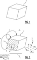
- Figure 1 shows a 2D display of a model 1 of an object to be 3D printed (or the object resulting from 3D printing itself).
- the present embodiment description will proceed under the assumption that figure 1 shows what is displayed in the GUI.
- the model 1 displayed on a 2D display such as a display screen in a Graphic User Interface (GUI) is highly simplified as a tilted cube to assist proper understanding of the present disclosure.
- GUI Graphic User Interface
- Figure 2 also shows the model 1 being displayed in a Graphic User Interface (GUI) 2, with tools 3, 5, 6, 7, 8 for manipulation.
- GUI Graphic User Interface
- a user is able to manipulate the displayed view of the model 1 using translation and rotation arrows 3, until a surface or face 4 comes into view (from a type of camera perspective) that the user wants to select.
- Surrounding a cursor 5 is an optional selection box 6.
- the model 1 is displayed relative to a reference 7, which may correspond with a build platform of a 3D printer.
- the user may select surface or face 4 to indicate his/her desire to keep a selected face or surface 4 free from support elements or posts 9 by selection of an appropriate option 8 from the possibilities of adding support elements or posts 9 or avoiding support elements or posts 9 at the selected surface or face 4, for example by clicking with the cursor 5 on the desired surface or face 4, and then also placing box 6 or at least cursor 5 on the surface or face 4 to be selected, and clicking again.
- the order may be reversed. Thereby, the entire surface or face 4 of the model is recognized as a selected surface or face 4 to be kept free - at least as much as possible - of support elements or posts 9.
- the surface or face 4 may be oriented correspondingly, relative to reference 7 of - for example - the build platform of a 3D printer.
- the model may be rotated along arrows A to position the surface or face 4 as much as possible away from the reference 7.
- the disclosure therefore provides automatic re-orienting the model 1 relative to the reference 7, to avoid addition of posts 9 at surface or face 4 (as much as possible). Since the user does not need to know the position of the reference 7 for the system, method and functionality of the present disclosure to be achieved, display of the reference 7 may be omitted. The only essential input / output is then that the user can indicate which surface or face 4 is to be kept free from support elements as much as possible.
- the system of the 3D printer, performing the method of the present disclosure will orient the object relative to the reference.
- the user may alternatively orient the object relative to the reference 7, for which display thereof may be important, to indicate thereby which surface(s) or face(s) is/are to be kept free of support elements or posts 9 (as much as possible). Therefore, the user may him- or herself change the orientation of the model 1 relative to the reference 7 using the manipulation keys 3, to set the surface or face 4 at a position and orientation relative to the reference 7, as a consequence of which the number of support elements or posts 9 is minimized in the selected surface or face 4.
- the reference should be indicated or visualised otherwise in the Graphic User Interface.
- support elements or posts 9 are added to the model, to provide the 3D printer with an extended model with added posts 9 for 3D printing of a supported object, in the above described manner, as shown in figure 3 .
- the posts 9 may be broken off as shown in figure 4 . Breaking off the posts 9 often leaves visible marks, which is why the present disclosure enables a purposeful selection by a user of surfaces or faces 4 which are to be kept free, at least as much as possible, of support elements or posts 9, as these more visible surfaces or faces of the object then need a minimum of (or even no) further processing, in particular smoothening.
Landscapes
- Engineering & Computer Science (AREA)
- Manufacturing & Machinery (AREA)
- Chemical & Material Sciences (AREA)
- Materials Engineering (AREA)
- Physics & Mathematics (AREA)
- Mechanical Engineering (AREA)
- Optics & Photonics (AREA)
- Human Computer Interaction (AREA)
- General Physics & Mathematics (AREA)
- Automation & Control Theory (AREA)
- Processing Or Creating Images (AREA)
Priority Applications (1)
| Application Number | Priority Date | Filing Date | Title |
|---|---|---|---|
| PL18839748T PL3710232T3 (pl) | 2017-11-14 | 2018-11-14 | Wspornik obiektu podczas drukowania 3d obiektu na podstawie modelu |
Applications Claiming Priority (2)
| Application Number | Priority Date | Filing Date | Title |
|---|---|---|---|
| NL2019907A NL2019907B1 (en) | 2017-11-14 | 2017-11-14 | Object support during 3d printing of an object based on a model |
| PCT/NL2018/050762 WO2019098828A2 (en) | 2017-11-14 | 2018-11-14 | Object support during 3d printing of an object based on a model |
Publications (2)
| Publication Number | Publication Date |
|---|---|
| EP3710232A2 EP3710232A2 (en) | 2020-09-23 |
| EP3710232B1 true EP3710232B1 (en) | 2022-02-16 |
Family
ID=61025016
Family Applications (1)
| Application Number | Title | Priority Date | Filing Date |
|---|---|---|---|
| EP18839748.3A Active EP3710232B1 (en) | 2017-11-14 | 2018-11-14 | Object support during 3d printing of an object based on a model |
Country Status (7)
| Country | Link |
|---|---|
| US (1) | US11235529B2 (pl) |
| EP (1) | EP3710232B1 (pl) |
| CN (1) | CN111629886B (pl) |
| ES (1) | ES2913772T3 (pl) |
| NL (1) | NL2019907B1 (pl) |
| PL (1) | PL3710232T3 (pl) |
| WO (1) | WO2019098828A2 (pl) |
Families Citing this family (3)
| Publication number | Priority date | Publication date | Assignee | Title |
|---|---|---|---|---|
| CN113733566B (zh) * | 2021-08-27 | 2023-06-06 | 深圳市创必得科技有限公司 | 等高支撑结构生成方法、装置、电子设备及存储介质 |
| US12405593B2 (en) * | 2021-11-17 | 2025-09-02 | Autodesk, Inc. | Computer aided design with geometry filtering to facilitate manufacturing |
| MX2023011448A (es) | 2022-09-30 | 2024-04-01 | Hasbro Inc | Accesorio de juguete y sistema de impresion. |
Family Cites Families (4)
| Publication number | Priority date | Publication date | Assignee | Title |
|---|---|---|---|---|
| JP5777136B2 (ja) * | 2007-09-17 | 2015-09-09 | スリーディー システムズ インコーポレーテッド | 固体自由形状製作により製造されるパーツのための領域に基づくサポート |
| US9844917B2 (en) * | 2014-06-13 | 2017-12-19 | Siemens Product Lifestyle Management Inc. | Support structures for additive manufacturing of solid models |
| US20160263837A1 (en) * | 2015-03-13 | 2016-09-15 | Carbon3D, Inc. | Methods, systems, and computer program products for determining fabrication parameters used in three-dimensional (3d) continuous liquid interface printing (clip) systems, and related printers |
| US20160274572A1 (en) * | 2015-03-19 | 2016-09-22 | Michael G. Littrell | Three Dimensional (3D) Printing and CAD File Quoting System |
-
2017
- 2017-11-14 NL NL2019907A patent/NL2019907B1/en not_active IP Right Cessation
-
2018
- 2018-11-14 PL PL18839748T patent/PL3710232T3/pl unknown
- 2018-11-14 WO PCT/NL2018/050762 patent/WO2019098828A2/en not_active Ceased
- 2018-11-14 CN CN201880073515.0A patent/CN111629886B/zh not_active Expired - Fee Related
- 2018-11-14 US US16/649,915 patent/US11235529B2/en active Active
- 2018-11-14 EP EP18839748.3A patent/EP3710232B1/en active Active
- 2018-11-14 ES ES18839748T patent/ES2913772T3/es active Active
Also Published As
| Publication number | Publication date |
|---|---|
| NL2019907B1 (en) | 2019-05-20 |
| US20200276763A1 (en) | 2020-09-03 |
| WO2019098828A3 (en) | 2019-06-13 |
| CN111629886B (zh) | 2022-06-03 |
| PL3710232T3 (pl) | 2022-06-20 |
| US11235529B2 (en) | 2022-02-01 |
| ES2913772T3 (es) | 2022-06-06 |
| WO2019098828A2 (en) | 2019-05-23 |
| EP3710232A2 (en) | 2020-09-23 |
| CN111629886A (zh) | 2020-09-04 |
Similar Documents
| Publication | Publication Date | Title |
|---|---|---|
| US11235529B2 (en) | Object support during 3D printing of an object based on a model | |
| US8121717B2 (en) | Three dimensional processing data setting system, method for setting three-dimensional processing data, computer program for setting three-dimensional processing data, medium with three-dimensional processing data stored therein that is readable by computer and laser processing equipment operated by the three-dimensional data | |
| US20190155965A1 (en) | Three-Dimensional (3D) Printing and CAD File Quoting System | |
| CN111479667B (zh) | 构建体积的零件填充 | |
| US8924002B2 (en) | Adaptive registration during precision graphics cutting from multiple sheets | |
| US20220317663A1 (en) | Method and apparatus for determining cutting parameters for a laser cutting machine | |
| CN104811570B (zh) | 电子设备及工作流程生成方法 | |
| US10338564B2 (en) | Remote material yield optimization for leather and other heterogeneous material | |
| EP1818800A1 (en) | Print data-editing apparatus and print data-editing program stored in computer readable medium | |
| WO2020250216A1 (en) | System and method for selection of a print head of a three-dimensional printer | |
| JP2011043998A (ja) | 画像解析方法及び画像解析装置 | |
| HK40026718A (en) | Object support during 3d printing of an object based on a model | |
| EP0314798B1 (en) | Nc data preparation for working curved surface | |
| US20250001700A1 (en) | Enhanced support generation techniques for additive fabrication | |
| US10931867B2 (en) | Image processing apparatus, robot and robot system | |
| EP3614254A1 (en) | Document processing system for processing a print job | |
| DE112021008153B4 (de) | Gerät und Programm zur Verlaufsverwaltung | |
| EP3690568A1 (en) | Cutting system | |
| US11443496B2 (en) | Three-dimensional object data generation apparatus, three-dimensional object forming apparatus, and non-transitory computer readable medium for setting attributes of voxels representing object | |
| EP4586070A1 (en) | A printer and a method of displaying an image at the user interface of the printer | |
| EP3774297A1 (en) | Object orientation and/or position for additive manufacturing | |
| JPH07200021A (ja) | 自動製品配列方法 | |
| EP3690569A1 (en) | Cutting system | |
| JP2018052053A (ja) | 印刷切断指示装置、印刷切断指示プログラム、印刷切断指示方法 | |
| CN116992507A (zh) | 石材大板选排版方法 |
Legal Events
| Date | Code | Title | Description |
|---|---|---|---|
| STAA | Information on the status of an ep patent application or granted ep patent |
Free format text: STATUS: UNKNOWN |
|
| STAA | Information on the status of an ep patent application or granted ep patent |
Free format text: STATUS: THE INTERNATIONAL PUBLICATION HAS BEEN MADE |
|
| PUAI | Public reference made under article 153(3) epc to a published international application that has entered the european phase |
Free format text: ORIGINAL CODE: 0009012 |
|
| STAA | Information on the status of an ep patent application or granted ep patent |
Free format text: STATUS: REQUEST FOR EXAMINATION WAS MADE |
|
| 17P | Request for examination filed |
Effective date: 20200506 |
|
| AK | Designated contracting states |
Kind code of ref document: A2 Designated state(s): AL AT BE BG CH CY CZ DE DK EE ES FI FR GB GR HR HU IE IS IT LI LT LU LV MC MK MT NL NO PL PT RO RS SE SI SK SM TR |
|
| AX | Request for extension of the european patent |
Extension state: BA ME |
|
| DAV | Request for validation of the european patent (deleted) | ||
| DAX | Request for extension of the european patent (deleted) | ||
| GRAP | Despatch of communication of intention to grant a patent |
Free format text: ORIGINAL CODE: EPIDOSNIGR1 |
|
| STAA | Information on the status of an ep patent application or granted ep patent |
Free format text: STATUS: GRANT OF PATENT IS INTENDED |
|
| INTG | Intention to grant announced |
Effective date: 20210923 |
|
| GRAS | Grant fee paid |
Free format text: ORIGINAL CODE: EPIDOSNIGR3 |
|
| GRAA | (expected) grant |
Free format text: ORIGINAL CODE: 0009210 |
|
| STAA | Information on the status of an ep patent application or granted ep patent |
Free format text: STATUS: THE PATENT HAS BEEN GRANTED |
|
| AK | Designated contracting states |
Kind code of ref document: B1 Designated state(s): AL AT BE BG CH CY CZ DE DK EE ES FI FR GB GR HR HU IE IS IT LI LT LU LV MC MK MT NL NO PL PT RO RS SE SI SK SM TR |
|
| REG | Reference to a national code |
Ref country code: GB Ref legal event code: FG4D |
|
| REG | Reference to a national code |
Ref country code: CH Ref legal event code: EP |
|
| REG | Reference to a national code |
Ref country code: DE Ref legal event code: R096 Ref document number: 602018031021 Country of ref document: DE |
|
| REG | Reference to a national code |
Ref country code: AT Ref legal event code: REF Ref document number: 1468635 Country of ref document: AT Kind code of ref document: T Effective date: 20220315 |
|
| REG | Reference to a national code |
Ref country code: IE Ref legal event code: FG4D |
|
| REG | Reference to a national code |
Ref country code: NL Ref legal event code: FP |
|
| REG | Reference to a national code |
Ref country code: ES Ref legal event code: FG2A Ref document number: 2913772 Country of ref document: ES Kind code of ref document: T3 Effective date: 20220606 |
|
| REG | Reference to a national code |
Ref country code: LT Ref legal event code: MG9D |
|
| REG | Reference to a national code |
Ref country code: AT Ref legal event code: MK05 Ref document number: 1468635 Country of ref document: AT Kind code of ref document: T Effective date: 20220216 |
|
| PG25 | Lapsed in a contracting state [announced via postgrant information from national office to epo] |
Ref country code: SE Free format text: LAPSE BECAUSE OF FAILURE TO SUBMIT A TRANSLATION OF THE DESCRIPTION OR TO PAY THE FEE WITHIN THE PRESCRIBED TIME-LIMIT Effective date: 20220216 Ref country code: RS Free format text: LAPSE BECAUSE OF FAILURE TO SUBMIT A TRANSLATION OF THE DESCRIPTION OR TO PAY THE FEE WITHIN THE PRESCRIBED TIME-LIMIT Effective date: 20220216 Ref country code: PT Free format text: LAPSE BECAUSE OF FAILURE TO SUBMIT A TRANSLATION OF THE DESCRIPTION OR TO PAY THE FEE WITHIN THE PRESCRIBED TIME-LIMIT Effective date: 20220616 Ref country code: NO Free format text: LAPSE BECAUSE OF FAILURE TO SUBMIT A TRANSLATION OF THE DESCRIPTION OR TO PAY THE FEE WITHIN THE PRESCRIBED TIME-LIMIT Effective date: 20220516 Ref country code: LT Free format text: LAPSE BECAUSE OF FAILURE TO SUBMIT A TRANSLATION OF THE DESCRIPTION OR TO PAY THE FEE WITHIN THE PRESCRIBED TIME-LIMIT Effective date: 20220216 Ref country code: HR Free format text: LAPSE BECAUSE OF FAILURE TO SUBMIT A TRANSLATION OF THE DESCRIPTION OR TO PAY THE FEE WITHIN THE PRESCRIBED TIME-LIMIT Effective date: 20220216 Ref country code: BG Free format text: LAPSE BECAUSE OF FAILURE TO SUBMIT A TRANSLATION OF THE DESCRIPTION OR TO PAY THE FEE WITHIN THE PRESCRIBED TIME-LIMIT Effective date: 20220516 |
|
| PG25 | Lapsed in a contracting state [announced via postgrant information from national office to epo] |
Ref country code: LV Free format text: LAPSE BECAUSE OF FAILURE TO SUBMIT A TRANSLATION OF THE DESCRIPTION OR TO PAY THE FEE WITHIN THE PRESCRIBED TIME-LIMIT Effective date: 20220216 Ref country code: GR Free format text: LAPSE BECAUSE OF FAILURE TO SUBMIT A TRANSLATION OF THE DESCRIPTION OR TO PAY THE FEE WITHIN THE PRESCRIBED TIME-LIMIT Effective date: 20220517 Ref country code: FI Free format text: LAPSE BECAUSE OF FAILURE TO SUBMIT A TRANSLATION OF THE DESCRIPTION OR TO PAY THE FEE WITHIN THE PRESCRIBED TIME-LIMIT Effective date: 20220216 Ref country code: AT Free format text: LAPSE BECAUSE OF FAILURE TO SUBMIT A TRANSLATION OF THE DESCRIPTION OR TO PAY THE FEE WITHIN THE PRESCRIBED TIME-LIMIT Effective date: 20220216 |
|
| PG25 | Lapsed in a contracting state [announced via postgrant information from national office to epo] |
Ref country code: IS Free format text: LAPSE BECAUSE OF FAILURE TO SUBMIT A TRANSLATION OF THE DESCRIPTION OR TO PAY THE FEE WITHIN THE PRESCRIBED TIME-LIMIT Effective date: 20220617 |
|
| PG25 | Lapsed in a contracting state [announced via postgrant information from national office to epo] |
Ref country code: SM Free format text: LAPSE BECAUSE OF FAILURE TO SUBMIT A TRANSLATION OF THE DESCRIPTION OR TO PAY THE FEE WITHIN THE PRESCRIBED TIME-LIMIT Effective date: 20220216 Ref country code: SK Free format text: LAPSE BECAUSE OF FAILURE TO SUBMIT A TRANSLATION OF THE DESCRIPTION OR TO PAY THE FEE WITHIN THE PRESCRIBED TIME-LIMIT Effective date: 20220216 Ref country code: RO Free format text: LAPSE BECAUSE OF FAILURE TO SUBMIT A TRANSLATION OF THE DESCRIPTION OR TO PAY THE FEE WITHIN THE PRESCRIBED TIME-LIMIT Effective date: 20220216 Ref country code: EE Free format text: LAPSE BECAUSE OF FAILURE TO SUBMIT A TRANSLATION OF THE DESCRIPTION OR TO PAY THE FEE WITHIN THE PRESCRIBED TIME-LIMIT Effective date: 20220216 Ref country code: DK Free format text: LAPSE BECAUSE OF FAILURE TO SUBMIT A TRANSLATION OF THE DESCRIPTION OR TO PAY THE FEE WITHIN THE PRESCRIBED TIME-LIMIT Effective date: 20220216 |
|
| REG | Reference to a national code |
Ref country code: DE Ref legal event code: R097 Ref document number: 602018031021 Country of ref document: DE |
|
| PG25 | Lapsed in a contracting state [announced via postgrant information from national office to epo] |
Ref country code: AL Free format text: LAPSE BECAUSE OF FAILURE TO SUBMIT A TRANSLATION OF THE DESCRIPTION OR TO PAY THE FEE WITHIN THE PRESCRIBED TIME-LIMIT Effective date: 20220216 |
|
| PLBE | No opposition filed within time limit |
Free format text: ORIGINAL CODE: 0009261 |
|
| STAA | Information on the status of an ep patent application or granted ep patent |
Free format text: STATUS: NO OPPOSITION FILED WITHIN TIME LIMIT |
|
| 26N | No opposition filed |
Effective date: 20221117 |
|
| PG25 | Lapsed in a contracting state [announced via postgrant information from national office to epo] |
Ref country code: SI Free format text: LAPSE BECAUSE OF FAILURE TO SUBMIT A TRANSLATION OF THE DESCRIPTION OR TO PAY THE FEE WITHIN THE PRESCRIBED TIME-LIMIT Effective date: 20220216 |
|
| PG25 | Lapsed in a contracting state [announced via postgrant information from national office to epo] |
Ref country code: MC Free format text: LAPSE BECAUSE OF FAILURE TO SUBMIT A TRANSLATION OF THE DESCRIPTION OR TO PAY THE FEE WITHIN THE PRESCRIBED TIME-LIMIT Effective date: 20220216 |
|
| REG | Reference to a national code |
Ref country code: CH Ref legal event code: PL |
|
| P01 | Opt-out of the competence of the unified patent court (upc) registered |
Effective date: 20230526 |
|
| PG25 | Lapsed in a contracting state [announced via postgrant information from national office to epo] |
Ref country code: LI Free format text: LAPSE BECAUSE OF NON-PAYMENT OF DUE FEES Effective date: 20221130 Ref country code: CZ Free format text: LAPSE BECAUSE OF NON-PAYMENT OF DUE FEES Effective date: 20221114 Ref country code: CH Free format text: LAPSE BECAUSE OF NON-PAYMENT OF DUE FEES Effective date: 20221130 |
|
| PG25 | Lapsed in a contracting state [announced via postgrant information from national office to epo] |
Ref country code: LU Free format text: LAPSE BECAUSE OF NON-PAYMENT OF DUE FEES Effective date: 20221114 |
|
| PG25 | Lapsed in a contracting state [announced via postgrant information from national office to epo] |
Ref country code: IE Free format text: LAPSE BECAUSE OF NON-PAYMENT OF DUE FEES Effective date: 20221114 |
|
| PG25 | Lapsed in a contracting state [announced via postgrant information from national office to epo] |
Ref country code: FR Free format text: LAPSE BECAUSE OF NON-PAYMENT OF DUE FEES Effective date: 20221130 |
|
| REG | Reference to a national code |
Ref country code: ES Ref legal event code: FD2A Effective date: 20231227 |
|
| PG25 | Lapsed in a contracting state [announced via postgrant information from national office to epo] |
Ref country code: ES Free format text: LAPSE BECAUSE OF NON-PAYMENT OF DUE FEES Effective date: 20221115 |
|
| PG25 | Lapsed in a contracting state [announced via postgrant information from national office to epo] |
Ref country code: ES Free format text: LAPSE BECAUSE OF NON-PAYMENT OF DUE FEES Effective date: 20221115 |
|
| PG25 | Lapsed in a contracting state [announced via postgrant information from national office to epo] |
Ref country code: CY Free format text: LAPSE BECAUSE OF FAILURE TO SUBMIT A TRANSLATION OF THE DESCRIPTION OR TO PAY THE FEE WITHIN THE PRESCRIBED TIME-LIMIT Effective date: 20220216 |
|
| PG25 | Lapsed in a contracting state [announced via postgrant information from national office to epo] |
Ref country code: PL Free format text: LAPSE BECAUSE OF NON-PAYMENT OF DUE FEES Effective date: 20221114 Ref country code: MK Free format text: LAPSE BECAUSE OF FAILURE TO SUBMIT A TRANSLATION OF THE DESCRIPTION OR TO PAY THE FEE WITHIN THE PRESCRIBED TIME-LIMIT Effective date: 20220216 Ref country code: HU Free format text: LAPSE BECAUSE OF FAILURE TO SUBMIT A TRANSLATION OF THE DESCRIPTION OR TO PAY THE FEE WITHIN THE PRESCRIBED TIME-LIMIT; INVALID AB INITIO Effective date: 20181114 |
|
| PG25 | Lapsed in a contracting state [announced via postgrant information from national office to epo] |
Ref country code: TR Free format text: LAPSE BECAUSE OF FAILURE TO SUBMIT A TRANSLATION OF THE DESCRIPTION OR TO PAY THE FEE WITHIN THE PRESCRIBED TIME-LIMIT Effective date: 20220216 |
|
| PG25 | Lapsed in a contracting state [announced via postgrant information from national office to epo] |
Ref country code: MT Free format text: LAPSE BECAUSE OF FAILURE TO SUBMIT A TRANSLATION OF THE DESCRIPTION OR TO PAY THE FEE WITHIN THE PRESCRIBED TIME-LIMIT Effective date: 20220216 |
|
| PGFP | Annual fee paid to national office [announced via postgrant information from national office to epo] |
Ref country code: NL Payment date: 20241126 Year of fee payment: 7 |
|
| PGFP | Annual fee paid to national office [announced via postgrant information from national office to epo] |
Ref country code: DE Payment date: 20241127 Year of fee payment: 7 |
|
| PGFP | Annual fee paid to national office [announced via postgrant information from national office to epo] |
Ref country code: BE Payment date: 20241127 Year of fee payment: 7 |
|
| PGFP | Annual fee paid to national office [announced via postgrant information from national office to epo] |
Ref country code: GB Payment date: 20241127 Year of fee payment: 7 |
|
| PGFP | Annual fee paid to national office [announced via postgrant information from national office to epo] |
Ref country code: IT Payment date: 20241122 Year of fee payment: 7 |