EP3710199B1 - Device and method for determining a position and/or orientation of a workpiece - Google Patents
Device and method for determining a position and/or orientation of a workpiece Download PDFInfo
- Publication number
- EP3710199B1 EP3710199B1 EP18799485.0A EP18799485A EP3710199B1 EP 3710199 B1 EP3710199 B1 EP 3710199B1 EP 18799485 A EP18799485 A EP 18799485A EP 3710199 B1 EP3710199 B1 EP 3710199B1
- Authority
- EP
- European Patent Office
- Prior art keywords
- workpiece
- unit
- radiation source
- electromagnetic radiation
- radiation
- Prior art date
- Legal status (The legal status is an assumption and is not a legal conclusion. Google has not performed a legal analysis and makes no representation as to the accuracy of the status listed.)
- Active
Links
- 238000000034 method Methods 0.000 title claims description 21
- 230000005855 radiation Effects 0.000 claims description 55
- 230000005670 electromagnetic radiation Effects 0.000 claims description 38
- 238000003754 machining Methods 0.000 claims description 34
- 238000012545 processing Methods 0.000 claims description 27
- 230000004048 modification Effects 0.000 description 11
- 238000012986 modification Methods 0.000 description 11
- 230000003287 optical effect Effects 0.000 description 6
- 239000000463 material Substances 0.000 description 4
- 238000001514 detection method Methods 0.000 description 3
- 238000011144 upstream manufacturing Methods 0.000 description 3
- 238000001816 cooling Methods 0.000 description 2
- 230000000694 effects Effects 0.000 description 2
- 238000010438 heat treatment Methods 0.000 description 2
- 238000005286 illumination Methods 0.000 description 2
- 239000000654 additive Substances 0.000 description 1
- 230000000996 additive effect Effects 0.000 description 1
- 238000004364 calculation method Methods 0.000 description 1
- 239000011248 coating agent Substances 0.000 description 1
- 238000000576 coating method Methods 0.000 description 1
- 230000000295 complement effect Effects 0.000 description 1
- 230000001276 controlling effect Effects 0.000 description 1
- 238000005520 cutting process Methods 0.000 description 1
- 230000001419 dependent effect Effects 0.000 description 1
- 238000010586 diagram Methods 0.000 description 1
- 238000006073 displacement reaction Methods 0.000 description 1
- 238000005553 drilling Methods 0.000 description 1
- 239000011521 glass Substances 0.000 description 1
- 238000012994 industrial processing Methods 0.000 description 1
- 238000004519 manufacturing process Methods 0.000 description 1
- 239000011159 matrix material Substances 0.000 description 1
- 238000003801 milling Methods 0.000 description 1
- 230000001681 protective effect Effects 0.000 description 1
- 230000001105 regulatory effect Effects 0.000 description 1
- 239000011343 solid material Substances 0.000 description 1
- 238000010408 sweeping Methods 0.000 description 1
- 238000003466 welding Methods 0.000 description 1
Images


Classifications
-
- B—PERFORMING OPERATIONS; TRANSPORTING
- B23—MACHINE TOOLS; METAL-WORKING NOT OTHERWISE PROVIDED FOR
- B23Q—DETAILS, COMPONENTS, OR ACCESSORIES FOR MACHINE TOOLS, e.g. ARRANGEMENTS FOR COPYING OR CONTROLLING; MACHINE TOOLS IN GENERAL CHARACTERISED BY THE CONSTRUCTION OF PARTICULAR DETAILS OR COMPONENTS; COMBINATIONS OR ASSOCIATIONS OF METAL-WORKING MACHINES, NOT DIRECTED TO A PARTICULAR RESULT
- B23Q17/00—Arrangements for observing, indicating or measuring on machine tools
- B23Q17/24—Arrangements for observing, indicating or measuring on machine tools using optics or electromagnetic waves
- B23Q17/2452—Arrangements for observing, indicating or measuring on machine tools using optics or electromagnetic waves for measuring features or for detecting a condition of machine parts, tools or workpieces
- B23Q17/2471—Arrangements for observing, indicating or measuring on machine tools using optics or electromagnetic waves for measuring features or for detecting a condition of machine parts, tools or workpieces of workpieces
-
- B—PERFORMING OPERATIONS; TRANSPORTING
- B23—MACHINE TOOLS; METAL-WORKING NOT OTHERWISE PROVIDED FOR
- B23Q—DETAILS, COMPONENTS, OR ACCESSORIES FOR MACHINE TOOLS, e.g. ARRANGEMENTS FOR COPYING OR CONTROLLING; MACHINE TOOLS IN GENERAL CHARACTERISED BY THE CONSTRUCTION OF PARTICULAR DETAILS OR COMPONENTS; COMBINATIONS OR ASSOCIATIONS OF METAL-WORKING MACHINES, NOT DIRECTED TO A PARTICULAR RESULT
- B23Q17/00—Arrangements for observing, indicating or measuring on machine tools
- B23Q17/22—Arrangements for observing, indicating or measuring on machine tools for indicating or measuring existing or desired position of tool or work
- B23Q17/2233—Arrangements for observing, indicating or measuring on machine tools for indicating or measuring existing or desired position of tool or work for adjusting the tool relative to the workpiece
-
- B—PERFORMING OPERATIONS; TRANSPORTING
- B23—MACHINE TOOLS; METAL-WORKING NOT OTHERWISE PROVIDED FOR
- B23Q—DETAILS, COMPONENTS, OR ACCESSORIES FOR MACHINE TOOLS, e.g. ARRANGEMENTS FOR COPYING OR CONTROLLING; MACHINE TOOLS IN GENERAL CHARACTERISED BY THE CONSTRUCTION OF PARTICULAR DETAILS OR COMPONENTS; COMBINATIONS OR ASSOCIATIONS OF METAL-WORKING MACHINES, NOT DIRECTED TO A PARTICULAR RESULT
- B23Q17/00—Arrangements for observing, indicating or measuring on machine tools
- B23Q17/24—Arrangements for observing, indicating or measuring on machine tools using optics or electromagnetic waves
- B23Q17/2428—Arrangements for observing, indicating or measuring on machine tools using optics or electromagnetic waves for measuring existing positions of tools or workpieces
-
- G—PHYSICS
- G01—MEASURING; TESTING
- G01B—MEASURING LENGTH, THICKNESS OR SIMILAR LINEAR DIMENSIONS; MEASURING ANGLES; MEASURING AREAS; MEASURING IRREGULARITIES OF SURFACES OR CONTOURS
- G01B11/00—Measuring arrangements characterised by the use of optical techniques
- G01B11/002—Measuring arrangements characterised by the use of optical techniques for measuring two or more coordinates
-
- G—PHYSICS
- G01—MEASURING; TESTING
- G01B—MEASURING LENGTH, THICKNESS OR SIMILAR LINEAR DIMENSIONS; MEASURING ANGLES; MEASURING AREAS; MEASURING IRREGULARITIES OF SURFACES OR CONTOURS
- G01B11/00—Measuring arrangements characterised by the use of optical techniques
- G01B11/02—Measuring arrangements characterised by the use of optical techniques for measuring length, width or thickness
- G01B11/026—Measuring arrangements characterised by the use of optical techniques for measuring length, width or thickness by measuring distance between sensor and object
Definitions
- the present invention relates to a device and a method for determining a position and / or orientation of a workpiece.
- a laser light source is often used which is set up to generate one or more lines of light on the surface of the workpiece during operation. The lines of light can then be detected by means of an optical sensor and evaluated by a processing unit connected downstream of the sensor on the basis of an image processing algorithm.
- the invention enriches the prior art in this regard, as Devices and methods according to the invention instead of a single radiation source comprise / use a radiation source pair or a beam splitter, which makes it easier to radiate electromagnetic radiation from different directions onto (partially) overlapping (in particular linear) areas of the surface, so that due to the geometry of the workpiece Shadowing effects can be reduced or avoided.
- the radiation sources or the beam splitter unit are set up to focus electromagnetic radiation on two directly adjacent or at least partially overlapping spatial curves during operation of the device or to radiate the electromagnetic radiation along two directly adjacent or intersecting surfaces.
- a device further comprises a sensor unit which is arranged in accordance with a defined positional relationship to the radiation sources or the beam splitter unit and which is set up to and / or from electromagnetic radiation emitted by the radiation source or radiation sources and reflected on a surface of the workpiece during operation of the device to detect electromagnetic radiation emitted from the surface of the workpiece, and a processing unit which is set up to determine the position and / or orientation of the workpiece relative to the processing unit on the basis of the detected electromagnetic radiation.
- the processing unit is set up to output an error signal if a distance between a first reflection track of the electromagnetic radiation on a surface, particularly preferably the surface of the workpiece, and a second reflection track of the electromagnetic radiation on the surface is outside a tolerance range.
- workpiece as used in the description and the claims, is to be understood in particular as an object made of a solid material that is to be changed by machining, e.g. B. material removed, material changed in its structure or (same or different) material is added (such as drilling, milling, welding, additive manufacturing, coating, etc.).
- processing unit as used in the description and the claims, is to be understood in particular as a group of components by which the change in the object is to be effected by z. B. the component group or parts of the component group act mechanically on the object or supply the object with energy or material.
- the term “radiation source” as used in the description and the claims is to be understood in particular as one or more diodes emitting electromagnetic radiation or a laser.
- the term “beam splitter unit” as used in the description and the claims is to be understood in particular as an optical assembly that separates a single light beam into two partial beams (for example by means of a partially transparent mirror).
- the beam splitter unit can have one or more optical components for deflecting one or both partial beams.
- the term “sensor unit” as used in the description and the claims is to be understood in particular as a component group which has one or more charge-coupled components (CCD sensors) or one or more CMOS components (CMOS sensors) .
- the component group can also include devices for detecting the temperature and / or deformation (e.g. a strain gauge) of the workpiece surface in order to measure not only the reflected electromagnetic radiation but also the heating / expansion of the workpiece (caused by the electromagnetic radiation) and when determining the position and / or to be able to take into account / use alignment of the workpiece relative to the machining unit.
- the space curves preferably lie in one plane or the surfaces are flat.
- the space curves are preferably straight.
- the first radiation source and / or the second radiation source can have a laser or an LED matrix and optical components arranged in the beam path that focus the electromagnetic radiation on a line (for example a line laser).
- a line for example a line laser
- the sensor unit preferably comprises a mirror arrangement which extends along the two directly adjoining or at least partially overlapping spatial curves or along the two intersecting surfaces and allows the electromagnetic radiation to be detected from different perspectives.
- a sensor of the sensor unit is preferably arranged on a bisector of a connecting line between the first radiation source and the second radiation source and / or the sensor unit fulfills the Scheimpflug condition.
- the device preferably has a measuring unit comprising the first radiation source, the second radiation source or the beam splitter unit and the sensor unit, the measuring unit being rotatably mounted in the device about an axis of rotation.
- the measuring unit can be pivotable about the machining unit or the receptacle, as a result of which the need to reposition the machining unit in order to align the measuring unit can be avoided during operation.
- the first radiation source, the second radiation source or the beam splitter unit and the sensor unit are preferably included in one measuring unit and the device has a plurality of such measuring units.
- measuring units can avoid the need to reposition the machining unit during operation, as may be necessary for aligning the measuring unit, for example, when a single measuring unit is present, which is arranged in a fixed position and in a fixed position relative to the machining unit.
- the beam paths of the measuring units preferably intersect.
- a beam curtain can be generated which partially or completely encloses the machining unit and which, with regard to the positioning of the machining unit for aligning a measuring unit, enables a largely or completely direction-independent machining of the workpiece.
- a method for determining a position and / or alignment of a workpiece comprises generating one or more pairs of reflection lines, each pair of reflection lines comprising two directly adjacent or at least partially overlapping and / or parallel reflection lines, particularly preferably lines of light, which generated by electromagnetic radiation emitted onto the surface from different directions.
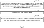
- a method according to the invention further comprises detecting the reflection lines and determining the position and / or orientation of the workpiece by means of triangulation on the basis of the reflection lines.
- a method according to the invention further comprises determining a distance between the reflection lines of a pair of reflection lines and outputting an error signal if the distance is outside a tolerance range.
- reflection lines of different reflection line pairs intersect on the surface of the workpiece and / or include angles of the same size.
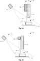
- Fig. 1 shows a schematic front view of a device 10 for determining the relative position and alignment between a processing unit 12 (process head) and a workpiece 14 to be processed by the processing unit 12.
- the device 10 comprises a first radiation source 16a and a second radiation source 16b for structured illumination of the workpiece 14.
- the radiation pattern projected onto the workpiece 14 (e.g. a line or a grid) is composed of two at least partially overlapping and, depending on the workpiece geometry, mutually complementary partial patterns that are generated by the incidence of electromagnetic radiation from different spatial directions.
- the spatial directions from which the electromagnetic rays impinge on the workpiece 14 are shown in FIG Fig. 1a
- the example shown is divided into two non-overlapping (spatial direction) areas which result from the different positions of the radiation sources 16a, 16b.
- the device 10 comprises a Sensor unit 18 with a sensor (for example a CCD or CMOS sensor) for detecting electromagnetic radiation and an upstream optics which images the workpiece surface onto the sensor surface.
- the upstream optics are preferably aligned in such a way that the Scheimpflug condition (image plane, projection plane and objective plane intersect in a straight line) with regard to the structured illumination is (at least approximately) fulfilled.
- the sensor unit 18 can be arranged or configured in such a way that the Scheimpflug condition with regard to the (surface of the) workpiece support 20 (as a projection plane ) is fulfilled, or the sensor unit 18 or the upstream optics can be rotated about an axis parallel to the workpiece support 20 in order to be able to adapt the device 10 to different workpiece geometries.
- Figure 1b shows a modification of the in Fig. 1a shown device 10, in which instead of two radiation sources 16a, 16b, a single radiation source 16 is provided, the electromagnetic radiation emitted by the radiation source 16 by means of a beam splitter unit 22 along different beam paths 26a, 26b (where in Figure 1b for the sake of clarity, only a single beam is shown) is directed.
- the beam splitter unit 22 can, for example, as in FIG Figure 1b shown have a partially (or semitransparent) mirror 22a and a further mirror 22b, which split the electromagnetic radiation emitted by the radiation source 16 and from different spatial directions (which on average correspond to the directions of the dashed lines hitting the surface of the workpiece 14 ) onto the surface of the workpiece 14.
- Fig. 2a shows another view of the in Fig. 1a
- the radiation sources 16a, 16b and the sensor unit 18 are arranged on one side (next to) the processing unit 12 and the radiation sources 16a, 16b (as also in FIG Fig. 1a shown) are aligned such that the beam path 26 falls perpendicularly onto the surface of the workpiece 14 or the workpiece support 20.
- the radiation sources 16a, 16b (as for example in Fig. 4 , Fig. 6 and Fig. 8 illustrated) also be inclined towards a work area 28 (e.g. a workpiece section / area to be processed or a process point) (i.e. not aligned perpendicular to the workpiece support 20 on average), whereby a distance between the structured lighting and the work area 28 may be ( further) can be reduced.
- a work area 28 e.g. a workpiece section / area to be processed or a process point
- the radiation sources 16a, 16b and the sensor unit 18 can be designed as a measuring unit 30 which is connected to the machining unit 12 in such a way that it is moved along with the machining unit 12 (when the machining unit 12 moves).
- Figure 2b shows another view of the in Figure 1b
- the device 10 shown here is analogous to that in Fig. 2a It can be seen that the radiation source 16, the beam splitter unit 22 and the sensor unit 18 are arranged on one side (next to) the processing unit 12 and (as in FIG Figure 1b shown) the beam splitter unit 22 is aligned such that the beam path 26 falls perpendicularly onto the surface of the workpiece 14 or the workpiece support 20 (this being as in connection with Fig. 2a explained alternatively can also be inclined towards the work area 28).
- the radiation source 16, the beam splitter unit 22 and the sensor unit 18 can be designed as a measuring unit 30 which is connected to the processing unit 12 in such a way that ( during a movement of the processing unit 12) is moved along with it.
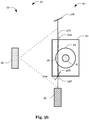
- Fig. 3a shows another view of the in Fig. 1a device 10 shown, according to a first embodiment.
- the electromagnetic radiation is emitted along two partially intersecting surfaces 32a, 32b, the cutting line or surface formed thereby at least partially sweeping over the workpiece surface.
- the electromagnetic radiation is focused on two spatial curves 34a, 34b, which run (at least in sections) along the surface of the workpiece support 20 or along the surface of the workpiece 14, as a result of which a reflection track 36 that can be detected by the sensor unit 18 is formed on the surface of the workpiece 14 a reflection line is generated.
- An (undesired) offset can occur between the spatial curves 34a, 34b, which widening or blurring the reflection track 36.
- a processing unit connected downstream of the sensor unit 18 can make a determination of the position and / or orientation of a workpiece 14 relative to the processing unit 12 a calculation of the position and / or orientation of the workpiece 14 dependent thereon, whether the offset exceeds a certain threshold value or output an error message when the threshold value is exceeded. Furthermore (before determining the position and / or orientation of the workpiece 14 relative to the machining unit 12 or when the threshold value is exceeded) a Calibration routine can be carried out, which is aimed at reducing the offset at least below the threshold value. As part of the calibration routine, for example, one or both radiation sources 16a, 16b (or optical components of the radiation sources 16a, 16b) can be aligned / adjusted.
- the position and, given a corresponding geometry of the workpiece 14, also the alignment of the workpiece 14 can be determined by means of triangulation.
- the position and / or orientation of the workpiece 14 relative to the machining unit 12 can then be used to position / align the machining unit 12 relative to the workpiece 14 at the beginning or during the machining of the workpiece 14, or to continuously monitor and / or monitor the relative position and / or orientation to control.
- unevenness in the surface of the workpiece 14 can be detected (and processed / compensated) or the relative movement between the workpiece 14 and the processing unit 12 can be regulated so that (in sections) a constant distance between the surface and the workpiece 14 and the processing unit 12 is maintained, which, for example, facilitates the programming of the machining unit 12 (or a control unit controlling the machining unit 12) with regard to free-form surfaces to be machined, since it is then sufficient to program flat paths.
- thermal radiation emitted by the workpiece 14 can also be detected.
- the detected thermal radiation can, for example, make it possible to determine an expansion of the workpiece 14 and to adjust the positioning / alignment of the machining unit 12 relative to the workpiece 14 accordingly.
- the thermal radiation can be used to improve the detection of the reflection track 36 in that local heating of the workpiece surface caused by the electromagnetic radiation directed onto the workpiece 14 is used to improve the accuracy in determining the course of the reflection track 36.
- Figure 3b shows another view of the in Figure 1b device 10 shown, to which the Fig. 3a
- the statements made apply analogously, with the radiation source 16 and / or the beam splitter unit 22 (or optical components of the beam splitter unit 22) being aligned / adjusted as part of the calibration routine.
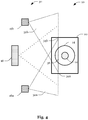
- Fig. 4 also shows a modification of the in Fig. 3a embodiment shown, but which also apply to the in Figure 3b The embodiment shown is transferable, the in Fig. 4 The modification shown is characterized in that the electromagnetic radiation moves along flat surfaces 32a, 32b is emitted and / or (instead of curved) can be focused on straight spatial curves 34a, 34b.
- the in Fig. 4 The modification shown, that the radiation sources 16a, 16b (as also in Fig. 6 and Fig. 8 illustrated) can be inclined towards the work area 28 (for example a workpiece section / area to be machined or a process point).
- the sensor unit 18 can be preceded by a mirror arrangement 38 which enables the workpiece 14 or the reflection track 36 to be detected from different perspectives.
- the sensor unit 18 can, for example, be divided into several detection areas, each detection area serving to detect the workpiece 14 or the reflection track 36 from one perspective (for example a central and two side views).
- several sensor units 18 can also be provided, which detect the workpiece 14 or the reflection track 36 from different perspectives.
- the perspectives can correspond to viewing locations which are spaced apart from one another parallel to the reflection track 36 in order to be able to compensate for shading caused by the geometry of the workpiece 14.
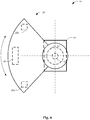
- the measuring unit 30 In order to be able to align the measuring unit 30 in the machining direction (feed direction), as in FIG Fig. 6 as a modification of the in Fig. 1a illustrated device, the measuring unit 30 about an axis, which, for example, runs through the machining unit 12 or a tool of the machining unit 12) can be pivoted.
- the processing unit 12 can be moved in an area (2 or 3-dimensional) extending opposite the workpiece support 20, the axis running perpendicular to the workpiece support or perpendicular to a surface of the workpiece 14.
- the radiation sources 16a, 16b (as also in Fig. 4 illustrated) towards the work area 28 (for example a workpiece section / area to be machined or a process point).
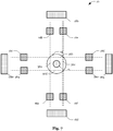
- the device 10 can be provided with a plurality of measuring units 30 instead of a single measuring unit 30.
- the measuring units 30 can generate a beam curtain enveloping the processing unit 12 (in the circumferential direction) (from intersecting beam paths) through which intersecting beam paths
- Reflection tracks 36 are generated.
- One or more measuring units 30 can also be arranged in their own housing (for example a housing which is designed for protection class IP 61) and can be integrated as a module in a processing machine.
- the housing can furthermore comprise a cooling device for cooling the housing interior or the measuring unit (s) 30.
- the power and data can also be supplied via an Ethernet connection.
- a separate power supply connection can be provided.
- the housing can have openings for emitting the electromagnetic radiation and for capturing the reflected electromagnetic radiation. The openings can be provided with exchangeable protective glasses.
- Fig. 9 shows a flowchart of a method for determining a position and / or orientation of the workpiece 14.
- the method begins with a step 40 of generating a pair of reflection lines on the workpiece 16, the pair of reflection lines having two reflection lines directly adjacent or at least partially overlapping includes.
- the position and / or orientation of the workpiece 14 is determined in step 44 by means of triangulation on the basis of the reflection lines.
Description
Die vorliegende Erfindung bezieht sich auf eine Vorrichtung und ein Verfahren zum Bestimmen einer Position und/oder Ausrichtung eines Werkstücks.The present invention relates to a device and a method for determining a position and / or orientation of a workpiece.
Bei der industriellen Bearbeitung von Werkstücken werden oftmals computergesteuerte Vorrichtungen verwendet, die eingerichtet sind, einen oder mehrere aufeinanderfolgende Arbeitsschritte auszuführen, wobei das Werkstück und eine das Werkstück bearbeitende Bearbeitungseinheit vor oder während der Bearbeitung relativ zueinander bewegt werden müssen. Dabei kann es zur Erhöhung der Bearbeitungseffizienz vorteilhaft sein, die Position und/oder Ausrichtung des Werkstücks mittels eines Sensors zu erfassen und die Relativbewegung zwischen Werkstück und Bearbeitungseinheit auf Basis der erfassten Sensordaten zu regeln.In the industrial processing of workpieces, computer-controlled devices are often used which are set up to carry out one or more successive work steps, the workpiece and a processing unit processing the workpiece having to be moved relative to one another before or during the processing. In order to increase the processing efficiency, it can be advantageous to detect the position and / or alignment of the workpiece by means of a sensor and to regulate the relative movement between the workpiece and the processing unit on the basis of the recorded sensor data.
Zur Erfassung der Position und/oder der Ausrichtung eines Werkstücks ist es bekannt, die Oberfläche des Werkstücks mit elektromagnetischer Strahlung strukturiert zu bestrahlen und durch Erfassen der an der Oberfläche reflektierten elektromagnetischen Strahlung mittels Triangulation die Position und/oder die Ausrichtung des Werkstücks zu berechnen. Zum strukturierten Bestrahlen der Oberfläche des Werkstücks mit elektromagnetischer Strahlung wird oftmals eine Laserlichtquelle eingesetzt, die eingerichtet ist, im Betrieb eine oder mehrere Lichtlinien auf der Oberfläche des Werkstücks zu erzeugen. Die Lichtlinien können dann mittels eines optischen Sensors erfasst und durch eine dem Sensor nachgeschaltete Verarbeitungseinheit auf Basis eines Bildverarbeitungsalgorithmus ausgewertet werden.To detect the position and / or the orientation of a workpiece, it is known to irradiate the surface of the workpiece with electromagnetic radiation in a structured manner and to calculate the position and / or the orientation of the workpiece by detecting the electromagnetic radiation reflected on the surface by means of triangulation. For the structured irradiation of the surface of the workpiece with electromagnetic radiation, a laser light source is often used which is set up to generate one or more lines of light on the surface of the workpiece during operation. The lines of light can then be detected by means of an optical sensor and evaluated by a processing unit connected downstream of the sensor on the basis of an image processing algorithm.
Der Gegenstand gemäß dem Oberbegriff von Anspruch 1 und die Lehre gemäß dem Oberbegriff von Anspruch 9 sind aus den Druckschriften
Weiterer relevanter Stand der Technik kann der Druckschrift
Die Erfindung bereichert diesbezüglich den Stand der Technik, als erfindungsgemäße Vorrichtungen und Verfahren anstatt einer einzelnen Strahlungsquelle ein Strahlungsquellenpaar bzw. einen Strahlteiler umfassen/einsetzen, was es erleichtert, elektromagnetische Strahlung aus unterschiedlichen Richtungen auf sich (teilweise) überlappende (insbesondere linienförmige) Bereiche der Oberfläche abzustrahlen, so dass durch die Geometrie des Werkstücks bedingte Abschattungseffekte reduziert bzw. vermieden werden können.The invention enriches the prior art in this regard, as Devices and methods according to the invention instead of a single radiation source comprise / use a radiation source pair or a beam splitter, which makes it easier to radiate electromagnetic radiation from different directions onto (partially) overlapping (in particular linear) areas of the surface, so that due to the geometry of the workpiece Shadowing effects can be reduced or avoided.
Eine erfindungsgemäße Vorrichtung zum Bestimmen einer Position und/oder Ausrichtung eines Werkstücks relativ zu einer Bearbeitungseinheit umfasst eine in einer definierten Lagebeziehung zur Bearbeitungseinheit oder in einer definierten Lagebeziehung zu einer Aufnahme, die zum Aufnehmen der Bearbeitungseinheit vorgesehen ist, angeordnete erste Strahlungsquelle und eine von der ersten Strahlungsquelle in einer Raumrichtung beabstandet angeordnete zweite Strahlungsquelle, oder eine Strahlteilereinheit. Die Strahlungsquellen bzw. die Strahlteilereinheit sind eingerichtet, während des Betriebs der Vorrichtung elektromagnetische Strahlung auf zwei unmittelbar aneinander angrenzende oder sich zumindest teilweise überlappende Raumkurven zu fokussieren oder die elektromagnetische Strahlung entlang zweier unmittelbar aneinander angrenzender oder sich schneidender Flächen abzustrahlen.A device according to the invention for determining a position and / or orientation of a workpiece relative to a machining unit comprises a first radiation source arranged in a defined positional relationship to the machining unit or in a defined positional relationship to a receptacle which is provided for holding the machining unit, and one of the first Radiation source, a second radiation source arranged spaced apart in one spatial direction, or a beam splitter unit. The radiation sources or the beam splitter unit are set up to focus electromagnetic radiation on two directly adjacent or at least partially overlapping spatial curves during operation of the device or to radiate the electromagnetic radiation along two directly adjacent or intersecting surfaces.
Eine erfindungsgemäße Vorrichtung umfasst ferner eine gemäß einer definierten Lagebeziehung zu den Strahlungsquellen bzw. der Strahlteilereinheit angeordnete Sensoreinheit, welche eingerichtet ist, während des Betriebs der Vorrichtung von der Strahlungsquelle bzw. den Strahlungsquellen abgestrahlte und an einer Oberfläche des Werkstücks reflektierte elektromagnetische Strahlung und/oder von der Oberfläche des Werkstücks abgestrahlte elektromagnetische Strahlung zu erfassen, und eine Verarbeitungseinheit, welche eingerichtet ist, die Position und/oder Ausrichtung des Werkstücks relativ zur Bearbeitungseinheit auf Basis der erfassten elektromagnetischen Strahlung zu bestimmen. Die Verarbeitungseinheit ist eingerichtet, ein Fehlersignal auszugeben, wenn ein Abstand zwischen einer ersten Reflexionsspur der elektromagnetischen Strahlung auf einer Oberfläche, besonders vorzugsweise der Oberfläche des Werkstücks, und einer zweiten Reflexionsspur der elektromagnetischen Strahlung auf der Oberfläche außerhalb eines Toleranzbereiches liegt.A device according to the invention further comprises a sensor unit which is arranged in accordance with a defined positional relationship to the radiation sources or the beam splitter unit and which is set up to and / or from electromagnetic radiation emitted by the radiation source or radiation sources and reflected on a surface of the workpiece during operation of the device to detect electromagnetic radiation emitted from the surface of the workpiece, and a processing unit which is set up to determine the position and / or orientation of the workpiece relative to the processing unit on the basis of the detected electromagnetic radiation. The processing unit is set up to output an error signal if a distance between a first reflection track of the electromagnetic radiation on a surface, particularly preferably the surface of the workpiece, and a second reflection track of the electromagnetic radiation on the surface is outside a tolerance range.
Dabei ist unter dem Begriff "Werkstück", wie er in der Beschreibung und den Ansprüchen verwendet wird, insbesondere ein Gegenstand aus einem festen Material zu verstehen, der durch die Bearbeitung verändert werden soll, indem z. B. Material abgetragen, Material in seiner Struktur verändert oder (gleiches oder anderes) Material angefügt wird (wie bspw. Bohren, Fräsen, Schweißen, additives Fertigen, Beschichten, etc.). Ferner ist unter dem Begriff "Bearbeitungseinheit", wie er in der Beschreibung und den Ansprüchen verwendet wird, insbesondere eine Bauteilgruppe zu verstehen, durch welche die Veränderung des Gegenstands bewirkt werden soll, indem z. B. die Bauteilgruppe bzw. Teile der Bauteilgruppe mechanisch auf den Gegenstand einwirken bzw. dem Gegenstand Energie oder Material zuführen.The term "workpiece", as used in the description and the claims, is to be understood in particular as an object made of a solid material that is to be changed by machining, e.g. B. material removed, material changed in its structure or (same or different) material is added (such as drilling, milling, welding, additive manufacturing, coating, etc.). Furthermore, the term "processing unit", as used in the description and the claims, is to be understood in particular as a group of components by which the change in the object is to be effected by z. B. the component group or parts of the component group act mechanically on the object or supply the object with energy or material.
Des Weiteren ist unter dem Begriff "Strahlungsquelle", wie er in der Beschreibung und den Ansprüchen verwendet wird, insbesondere eine oder mehrere elektromagnetische Strahlung emittierende Dioden oder ein Laser zu verstehen. Zudem ist unter dem Begriff "Strahlteilereinheit", wie er in der Beschreibung und den Ansprüchen verwendet wird, insbesondere eine optische Baugruppe zu verstehen, die einen einzelnen Lichtstrahl in zwei Teilstrahlen trennt (bspw. mittels eines teildurchlässigen Spiegels). Ferner kann die Strahlteilereinheit ein oder mehrere optische Bauelemente zum Ablenken eines oder beider Teilstrahlen aufweisen.Furthermore, the term “radiation source” as used in the description and the claims is to be understood in particular as one or more diodes emitting electromagnetic radiation or a laser. In addition, the term "beam splitter unit" as used in the description and the claims is to be understood in particular as an optical assembly that separates a single light beam into two partial beams (for example by means of a partially transparent mirror). Furthermore, the beam splitter unit can have one or more optical components for deflecting one or both partial beams.
Ferner ist unter dem Begriff "Sensoreinheit", wie er in der Beschreibung und den Ansprüchen verwendet wird, insbesondere eine Bauteilgruppe zu verstehen, die ein oder mehrere ladungsgekoppelte Bauteile (CCD-Sensoren) oder ein oder mehrere CMOS-Bauteile (CMOS-Sensoren) aufweist. Die Bauteilgruppe kann zudem Einrichtungen zum Erfassen der Temperatur und/oder Verformung (bspw. einen Dehnungsmessstreifen) der Werkstückoberfläche umfassen, um neben der reflektierten elektromagnetischen Strahlung auch die (durch die elektromagnetische Strahlung hervorgerufene) Erwärmung/Ausdehnung des Werkstücks messen und bei der Bestimmung der Position und/oder Ausrichtung des Werkstücks relativ zur Bearbeitungseinheit berücksichtigen/verwenden zu können.Furthermore, the term “sensor unit” as used in the description and the claims is to be understood in particular as a component group which has one or more charge-coupled components (CCD sensors) or one or more CMOS components (CMOS sensors) . The component group can also include devices for detecting the temperature and / or deformation (e.g. a strain gauge) of the workpiece surface in order to measure not only the reflected electromagnetic radiation but also the heating / expansion of the workpiece (caused by the electromagnetic radiation) and when determining the position and / or to be able to take into account / use alignment of the workpiece relative to the machining unit.
Vorzugsweise liegen die Raumkurven in einer Ebene bzw. sind die Flächen eben.The space curves preferably lie in one plane or the surfaces are flat.
Vorzugsweise sind die Raumkurven gerade.The space curves are preferably straight.
Bspw. kann die erste Strahlungsquelle und/oder die zweite Strahlungsquelle einen Laser oder eine LED-Matrix und im Strahlengang angeordnete optische Bauteile aufweisen, die die elektromagnetische Strahlung auf eine Linie fokussieren (bspw. einen Linienlaser).For example, the first radiation source and / or the second radiation source can have a laser or an LED matrix and optical components arranged in the beam path that focus the electromagnetic radiation on a line (for example a line laser).
Vorzugsweise umfasst die Sensoreinheit eine Spiegelanordnung, die sich entlang der zwei unmittelbar aneinander angrenzenden oder sich zumindest teilweise überlappenden Raumkurven bzw. entlang der zwei sich schneidenden Flächen erstreckt und ein Erfassen der elektromagnetischen Strahlung aus unterschiedlichen Perspektiven erlaubt.The sensor unit preferably comprises a mirror arrangement which extends along the two directly adjoining or at least partially overlapping spatial curves or along the two intersecting surfaces and allows the electromagnetic radiation to be detected from different perspectives.
Dies erleichtert es, in unterschiedliche Raumrichtungen reflektierte/abgestrahlte elektromagnetische Strahlung mit einem einzelnen Sensor der Sensoreinheit zu erfassen, und durch die Geometrie des Werkstücks bedingte und aus der Position des Sensors resultierende Abschattungseffekte zu reduzieren bzw. zu vermeiden.This makes it easier to detect electromagnetic radiation reflected / emitted in different spatial directions with a single sensor of the sensor unit, and to reduce or avoid shadowing effects caused by the geometry of the workpiece and resulting from the position of the sensor.
Vorzugsweise ist ein Sensor der Sensoreinheit auf einer Mittelhalbierenden einer Verbindungslinie zwischen der ersten Strahlungsquelle und der zweiten Strahlungsquelle angeordnet und/oder erfüllt die Sensoreinheit die Scheimpflug-Bedingung.A sensor of the sensor unit is preferably arranged on a bisector of a connecting line between the first radiation source and the second radiation source and / or the sensor unit fulfills the Scheimpflug condition.
Vorzugsweise weist die Vorrichtung eine Messeinheit, umfassend die erste Strahlungsquelle, die zweite Strahlungsquelle bzw. die Strahlteilereinheit und die Sensoreinheit auf, wobei die Messeinheit in der Vorrichtung um eine Rotationsachse drehbar gelagert ist.The device preferably has a measuring unit comprising the first radiation source, the second radiation source or the beam splitter unit and the sensor unit, the measuring unit being rotatably mounted in the device about an axis of rotation.
Dies vereinfacht das Ausrichten der Messeinheit. Bspw. kann die Messeinheit um die Bearbeitungseinheit oder die Aufnahme schwenkbar sein, wodurch im Betrieb die Notwendigkeit einer Umpositionierung der Bearbeitungseinheit zum Ausrichten der Messeinheit vermieden werden kann.This simplifies the alignment of the measuring unit. For example, the measuring unit can be pivotable about the machining unit or the receptacle, as a result of which the need to reposition the machining unit in order to align the measuring unit can be avoided during operation.
Vorzugsweise sind die erste Strahlungsquelle, die zweite Strahlungsquelle bzw. die Strahlteilereinheit und die Sensoreinheit in einer Messeinheit umfasst und die Vorrichtung weist eine Vielzahl solcher Messeinheiten auf.The first radiation source, the second radiation source or the beam splitter unit and the sensor unit are preferably included in one measuring unit and the device has a plurality of such measuring units.
Durch mehrere Messeinheiten kann im Betrieb die Notwendigkeit einer Umpositionierung der Bearbeitungseinheit, wie sie bspw. bei Vorhandensein einer einzelnen Messeinheit, welche in fixer Position und Ausrichtung relativ zur Bearbeitungseinheit angeordnet ist, zum Ausrichten der Messeinheit notwendig sein kann, vermieden werden.Several measuring units can avoid the need to reposition the machining unit during operation, as may be necessary for aligning the measuring unit, for example, when a single measuring unit is present, which is arranged in a fixed position and in a fixed position relative to the machining unit.
Vorzugsweise schneiden sich Strahlengänge der Messeinheiten.The beam paths of the measuring units preferably intersect.
Dadurch kann, bspw. durch um die Bearbeitungseinheit angeordnete Messeinheiten, ein die Bearbeitungseinheit teilweise oder vollständig umschließender Strahlenvorhang erzeugt werden, der in Hinblick auf die Positionierung der Bearbeitungseinheit zum Ausrichten einer Messeinheit eine weitgehend oder vollständig richtungsunabhängige Bearbeitung des Werkstücks ermöglicht.As a result, for example, by measuring units arranged around the machining unit, a beam curtain can be generated which partially or completely encloses the machining unit and which, with regard to the positioning of the machining unit for aligning a measuring unit, enables a largely or completely direction-independent machining of the workpiece.
Ein erfindungsgemäßes Verfahren zum Bestimmen einer Position und/oder Ausrichtung eines Werkstücks umfasst ein Erzeugen eines oder mehrerer Reflexionslinien-Paare, wobei jedes Reflexionslinien-Paar zwei unmittelbar aneinander angrenzende oder sich zumindest teilweise überlappende und/oder parallele Reflexionslinien, besonders vorzugsweise Lichtlinien, umfasst, die durch aus unterschiedlichen Richtungen auf die Oberfläche abgestrahlte elektromagnetische Strahlung erzeugt werden. Ein erfindungsgemäßes Verfahren umfasst ferner ein Erfassen der Reflexionslinien und ein Bestimmen der Position und/oder Ausrichtung des Werkstücks mittels Triangulation auf Basis der Reflexionslinien. Ein erfindungsgemäßes Verfahren umfasst ferner ein Bestimmen eines Abstands der Reflexionslinien eines Reflexionslinien-Paares und ein Ausgeben eines Fehlersignals, wenn der Abstand außerhalb eines Toleranzbereiches liegt.A method according to the invention for determining a position and / or alignment of a workpiece comprises generating one or more pairs of reflection lines, each pair of reflection lines comprising two directly adjacent or at least partially overlapping and / or parallel reflection lines, particularly preferably lines of light, which generated by electromagnetic radiation emitted onto the surface from different directions. A method according to the invention further comprises detecting the reflection lines and determining the position and / or orientation of the workpiece by means of triangulation on the basis of the reflection lines. A method according to the invention further comprises determining a distance between the reflection lines of a pair of reflection lines and outputting an error signal if the distance is outside a tolerance range.
Vorzugsweise schneiden sich Reflexionslinien unterschiedlicher Reflexionslinien-Paare auf der Oberfläche des Werkstücks und/oder schließen gleich große Winkel ein.Preferably, reflection lines of different reflection line pairs intersect on the surface of the workpiece and / or include angles of the same size.
Ferner versteht es sich, dass alle Merkmale (bevorzugter Ausführungsformen) erfindungsgemäßer Vorrichtungen auch Merkmale (bevorzugter Ausführungsformen) erfindungsgemäßer Verfahren sein können, welche sich auf die Verwendung erfindungsgemäßer Vorrichtungen beziehen, und umgekehrt.Furthermore, it goes without saying that all features (preferred embodiments) of devices according to the invention can also be features (preferred embodiments) of methods according to the invention, which relate to the use of devices according to the invention, and vice versa.
Die Erfindung wird nachfolgend in der detaillierten Beschreibung anhand von Ausführungsbeispielen erläutert, wobei auf Zeichnungen Bezug genommen wird, in denen:
-
Fig. 1a eine schematische Vorderansicht einer beispielhaften Ausgestaltung einer erfindungsgemäßen Vorrichtung zeigt; - Fig. 113 eine schematische Vorderansicht einer Abwandlung der in
Fig. 1a gezeigten beispielhaften Ausgestaltung zeigt; -
Fig. 2a eine schematische Seitenansicht der inFig. 1a gezeigten beispielhaften Ausgestaltung zeigt; -
Fig. 2b eine schematische Seitenansicht der inFig. 1b gezeigten Abwandlung zeigt; -
Fig. 3a eine schematische Draufsicht auf die inFig. 1a gezeigte beispielhafte Ausgestaltung zeigt, gemäß einer ersten Ausführungsform; -
Fig. 3b eine schematische Draufsicht auf die inFig. 1b gezeigte Abwandlung zeigt; -
Fig. 4 eine schematische Draufsicht auf die inFig. 1a gezeigte beispielhafte Ausgestaltung zeigt, gemäß einer zweiten Ausführungsform; -
Fig. 5 eine Abwandlung der inFig. 1a bis 4 gezeigten Ausführungsformen illustriert; -
Fig. 6 zusätzliche (optionale) Elemente der inFig. 1a bis 5 gezeigten Ausführungsformen illustriert; -
Fig. 7 weitere (optionale) Elemente der inFig. 1a bis 6 gezeigten Ausführungsformen illustriert; -
Fig. 8 weitere (optionale) Elemente der inFig. 1a bis 7 gezeigten Ausführungsformen illustriert; und -
Fig. 9 ein Flussdiagramm eines Verfahrens zum Bestimmen einer Position und/oder Ausrichtung eines Werkstücks zeigt.
-
Fig. 1a shows a schematic front view of an exemplary embodiment of a device according to the invention; - 113 is a schematic front view of a modification of the in
Fig. 1a shows the exemplary embodiment shown; -
Fig. 2a a schematic side view of the inFig. 1a shows the exemplary embodiment shown; -
Figure 2b a schematic side view of the inFigure 1b shows the modification shown; -
Fig. 3a a schematic plan view of the inFig. 1a shows the exemplary embodiment shown, according to a first embodiment; -
Figure 3b a schematic plan view of the inFigure 1b shows modification shown; -
Fig. 4 a schematic plan view of the inFig. 1a shows the exemplary embodiment shown, according to a second embodiment; -
Fig. 5 a modification of the inFIGS. 1a to 4 illustrated embodiments shown; -
Fig. 6 additional (optional) elements of the inFigs. 1a to 5 illustrated embodiments shown; -
Fig. 7 further (optional) elements of the inFigs. 1a to 6 illustrated embodiments shown; -
Fig. 8 further (optional) elements of the inFigures 1a to 7 illustrated embodiments shown; and -
Fig. 9 shows a flow diagram of a method for determining a position and / or orientation of a workpiece.
Dabei sind in den Zeichnungen gleiche und funktional ähnliche Elemente durch gleiche Bezugszeichen gekennzeichnet. Jedoch versteht es sich, dass nicht notwendigerweise alle Elemente in allen Zeichnungen gezeigt sind und dass die gezeigten Elemente nicht notwendigerweise maßstabsgetreu dargestellt sind.Identical and functionally similar elements are identified by the same reference symbols in the drawings. However, it should be understood that not necessarily all elements are shown in all of the drawings, and that the elements shown are not necessarily drawn to scale.
Zum Erfassen der strukturierten Beleuchtung umfasst die Vorrichtung 10 eine Sensoreinheit 18 mit einem Sensor (bspw. ein CCD- oder CMOS-Sensor) zum Erfassen elektromagnetischer Strahlung und einer vorgeschalteten Optik, die die WerkstückOberfläche auf die Sensoroberfläche abbildet. Die vorgeschaltete Optik ist dabei vorzugsweise so ausgerichtet, dass die Scheimpflug-Bedingung (Bildebene, Projektionsebene und Objektivebene schneiden sich in einer Geraden) hinsichtlich der strukturierten Beleuchtung (zumindest näherungsweise) erfüllt ist. Ist die Werkstückgeometrie vorab nicht bekannt oder wird die Vorrichtung 10 bei der Bearbeitung von Werkstücken 14 unterschiedlicher Geometrie verwendet, kann die Sensoreinheit 18 so angeordnet bzw. ausgestaltet sein, dass die Scheimpflug-Bedingung in Hinblick auf die (Oberfläche der) Werkstückauflage 20 (als Projektionsebene) erfüllt ist, oder die Sensoreinheit 18 bzw. die vorgeschaltete Optik um eine Achse parallel zur Werkstückauflage 20 drehbar sind, um die Vorrichtung 10 an unterschiedliche Werkstückgeometrien anpassen zu können.To detect the structured lighting, the
Um eine Verlagerung des Arbeitsbereichs 28 bei einer Relativbewegung zwischen der Bearbeitungseinheit 12 und dem Werkstück 14 zu kompensieren, können die Strahlungsquellen 16a, 16b und die Sensoreinheit 18 als Messeinheit 30 ausgebildet sein, die mit der Bearbeitungseinheit 12 derart verbunden ist, dass sie (bei einer Bewegung der Bearbeitungseinheit 12) mit dieser mitbewegt wird.In order to shift the
Um eine Verlagerung des Arbeitsbereichs 28 mit einer Relativbewegung zwischen der Bearbeitungseinheit 12 und dem Werkstück 14 zu kompensieren, können die Strahlungsquelle 16, die Strahlteilereinheit 22 und die Sensoreinheit 18 als Messeinheit 30 ausgebildet sein, die mit der Bearbeitungseinheit 12 derart verbunden ist, dass sie (bei einer Bewegung der Bearbeitungseinheit 12) mit dieser mitbewegt wird.In order to compensate for a displacement of the working
Daher kann eine der Sensoreinheit 18 nachgeschaltete Verarbeitungseinheit (bspw. ein Rechner mit einem Bildverarbeitungsprogramm, nicht gezeigt) eine Bestimmung der Position und/oder Ausrichtung eines Werkstücks 14 relativ zur Bearbeitungseinheit 12 eine Berechnung der Position und/oder Ausrichtung des Werkstücks 14 davon abhängig machen, ob der Versatz einen bestimmten Schwellenwert überschreitet bzw. beim Überschreiten des Schwellenwerts eine Fehlermeldung ausgeben. Ferner kann (vor dem Bestimmen der Position und/oder Ausrichtung des Werkstücks 14 relativ zur Bearbeitungseinheit 12 oder wenn der Schwellenwert überschritten wird) eine Kalibrierungsroutine durchgeführt werden, die darauf gerichtet ist, den Versatz zumindest unter den Schwellenwert zu reduzieren. Im Rahmen der Kalibrierungsroutine kann bspw. ein Ausrichten/Justieren einer oder beider Strahlungsquellen 16a, 16b (bzw. optischer Bauteile der Strahlungsquellen 16a, 16b) erfolgen.Therefore, a processing unit connected downstream of the sensor unit 18 (for example a computer with an image processing program, not shown) can make a determination of the position and / or orientation of a
Durch das Erfassen der (hinreichend scharfen) Reflexionsspur 36 kann dann die Position und bei entsprechender Geometrie des Werkstücks 14 auch die Ausrichtung des Werkstücks 14 mittels Triangulation bestimmt werden. Position und/oder Ausrichtung des Werkstücks 14 relativ zur Bearbeitungseinheit 12 können dann verwendet werden, um die Bearbeitungseinheit 12 am Anfang oder während der Bearbeitung des Werkstücks 14 relativ zum Werkstück 14 zu positionieren/auszurichten bzw. die Relativposition und/oder Ausrichtung fortlaufend zu überwachen bzw. zu steuern.By detecting the (sufficiently sharp)
Bspw. können Unebenheiten in der Oberfläche des Werkstücks 14 erkannt (und bearbeitet/kompensiert) werden oder die Relativbewegung zwischen dem Werkstück 14 und der Bearbeitungseinheit 12 so geregelt werden, dass (abschnittsweise) ein konstanter Abstand zwischen der Oberfläche und des Werkstücks 14 und der Bearbeitungseinheit 12 gewahrt wird, was bspw. die Programmierung der Bearbeitungseinheit 12 (bzw. einer die Bearbeitungseinheit 12 steuernde Steuereinheit) hinsichtlich zu bearbeitender Freiformflächen erleichtert, da es dann ausreicht, ebene Bahnen zu programmieren.For example, unevenness in the surface of the
Ferner kann neben der an der Oberfläche des Werkstücks 14 reflektierten elektromagnetischen Strahlung auch eine vom Werkstück 14 abgestrahlte Wärmestrahlung erfasst werden. Die erfasste Wärmestrahlung kann bspw. ermöglichen, eine Ausdehnung des Werkstücks 14 zu bestimmen und eine entsprechende Anpassung der Positionierung/Ausrichtung der Bearbeitungseinheit 12 relativ zum Werkstück 14 vorzunehmen. Zudem kann die Wärmestrahlung genutzt werden, um die Erfassung der Reflexionsspur 36 zu verbessern, indem eine durch die auf das Werkstück 14 gelenkte elektromagnetische Strahlung verursachte lokale Erwärmung der Werkstückoberfläche genutzt wird, die Genauigkeit bei der Bestimmung des Verlaufs der Reflexionsspur 36 zu verbessern.Furthermore, in addition to the electromagnetic radiation reflected on the surface of the
Wie in
Um die Messeinheit 30 in Bearbeitungsrichtung (Vorschubrichtung) ausrichten zu können, kann, wie in
Ferner kann, wie in
Reflexionsspuren 36 erzeugt werden.Reflection tracks 36 are generated.
Zudem können, wie in
Eine oder mehrere Messeinheiten 30 können zudem in einem eigenen Gehäuse angeordnet sein (bspw. ein Gehäuse, welches für die Schutzklasse IP 61 ausgelegt ist) und als Modul in eine Bearbeitungsmaschine integrierbar sein. Das Gehäuse kann ferner eine Kühleinrichtung zum Kühlen des Gehäuseinnenraums bzw. der Messeinheit(en) 30 umfassen. Die Strom- und Datenversorgung kann des Weiteren über eine Ethernet-Verbindung erfolgen. Zusätzlich kann ein separater Stromversorgunganschluss vorgesehen sein. Für das Ausstrahlen der elektromagnetischen Strahlung und das Erfassen der reflektierten elektromagnetischen Strahlung kann das Gehäuse Öffnungen aufweisen. Die Öffnungen können mit austauschbaren Schutzgläsern versehen sein.One or
- 1010
- Vorrichtungcontraption
- 1212th
- BearbeitungseinheitMachining unit
- 1414th
- Werkstückworkpiece
- 1616
- StrahlungsquelleRadiation source
- 1818th
- SensoreinheitSensor unit
- 2020th
- WerkstückauflageWorkpiece support
- 2222nd
- StrahlteilereinheitBeam splitter unit
- 2424
- AblenkeinrichtungDeflector
- 2626th
- StrahlengangBeam path
- 2828
- ArbeitsbereichWorkspace
- 3030th
- MesseinheitMeasuring unit
- 3232
- Flächearea
- 3434
- RaumkurveSpace curve
- 3636
- ReflexionsspurReflection trail
- 3838
- SpiegelanordnungMirror arrangement
- 4040
- ProzessschrittProcess step
- 4242
- ProzessschrittProcess step
- 4444
- ProzessschrittProcess step
Claims (10)
- A device (10) for determining a position and/or orientation of a workpiece (14) relative to a machining unit (12), comprising:a first radiation source (16) arranged in a defined positional relationship to the machining unit (12) or in a defined positional relationship to a support, which is provided to accommodate the machining unit (12);a second radiation source (16) or a beam splitter unit (22) arranged at a distance from the first radiation source (16) in a spatial direction;wherein the radiation sources (16) and/or the beam splitter unit (22) is/are designed, during operation of the device (10), to focus electromagnetic radiation onto two immediately adjacent or at least partially overlapping spatial curves (34) or to emit electromagnetic radiation along two immediately adjacent or intersecting surfaces (32);a sensor unit arranged in accordance with a defined positional relationship to the radiation sources (16) and/or the beam splitter unit (22), which is designed, during operation of the device (10), to detect electromagnetic radiation emitted by the first radiation source (16) and/or the radiation sources (16) and reflected on a surface of the workpiece (14) and/or electromagnetic radiation emitted by the surface of the workpiece (14); anda processing unit, which is designed to determine the position and/or orientation of the workpiece (14) relative to the machining unit (12) on the basis of the electromagnetic radiation detected;characterised in thatthe processing unit is designed to issue an error signal when a distance between a first reflection path (36) of the electromagnetic radiation on a surface and a second reflection path (36) of the electromagnetic radiation on the surface lies outside a tolerance range.
- The device (10) according to claim 1, wherein the spatial curves (34) lie in a plane and/or the surfaces (32) are level.
- The device (10) according to claim 1 or 2, wherein the spatial curves (34) are straight.
- The device (10) according to any of claims 1 to 3, wherein the sensor unit (18) comprises a mirror arrangement (38), which extends along the two immediately adjacent or at least partially overlapping spatial curves (34) and/or along the two intersecting surfaces (32) and allows the electromagnetic radiation to be detected from different perspectives.
- The device (10) according to any of claims 1 to 4, wherein a sensor of the sensor unit (18) is arranged on a bisecting line of a connecting line between the first radiation source (16) and the second radiation source (16) and/or the sensor unit (18) fulfils the Scheimpflug condition.
- The device (10) according to any of claims 1 to 5, wherein the device (10) has a measuring unit (30), comprising the first radiation source (16), the second radiation source (16) and/or the beam splitter unit (22) and the sensor unit (18), wherein the measuring unit (30) is rotatably mounted in the device (10) about an axis of rotation.
- The device (10) according to any of claims 1 to 6, wherein the first radiation source (16), the second radiation source (16) and/or the beam splitter unit (22) and the sensor unit (18) are included in a measuring unit (30) and the device (10) has a plurality of such measuring units (30).
- The device (10) according to claim 7, wherein beam paths 26 of the measuring units (30) intersect.
- A method for determining a position and/or orientation of a workpiece (14), comprising:generating (40) one or more pairs of reflection lines, wherein each pair of reflection lines comprises two immediately adjacent or at least partially overlapping and/or parallel reflection lines, preferably light lines, which are generated by electromagnetic radiation emitted from different directions onto the surface;detecting (42) the reflection lines; anddetermining (44) the position and/or orientation of the workpiece (14) by means of triangulation on the basis of the reflection line;characterised in that the method further comprisesdetermining a distance of the reflection lines of a pair of reflection lines and issuing an error signal, when the distance lies outside a tolerance range.
- The method according to claim 9, wherein reflection lines of different pairs of reflection lines intersect on the surface of the workpiece (14) and/or involve equally large angles.
Applications Claiming Priority (2)
| Application Number | Priority Date | Filing Date | Title |
|---|---|---|---|
| DE102017126786.7A DE102017126786A1 (en) | 2017-11-14 | 2017-11-14 | Apparatus and method for determining a position and / or orientation of a workpiece |
| PCT/EP2018/080035 WO2019096595A1 (en) | 2017-11-14 | 2018-11-02 | Device and method for determining a position and/or orientation of a workpiece |
Publications (2)
| Publication Number | Publication Date |
|---|---|
| EP3710199A1 EP3710199A1 (en) | 2020-09-23 |
| EP3710199B1 true EP3710199B1 (en) | 2021-10-13 |
Family
ID=64172479
Family Applications (1)
| Application Number | Title | Priority Date | Filing Date |
|---|---|---|---|
| EP18799485.0A Active EP3710199B1 (en) | 2017-11-14 | 2018-11-02 | Device and method for determining a position and/or orientation of a workpiece |
Country Status (3)
| Country | Link |
|---|---|
| EP (1) | EP3710199B1 (en) |
| DE (1) | DE102017126786A1 (en) |
| WO (1) | WO2019096595A1 (en) |
Families Citing this family (3)
| Publication number | Priority date | Publication date | Assignee | Title |
|---|---|---|---|---|
| DE102020101172A1 (en) * | 2020-01-20 | 2021-07-22 | Homag Gmbh | Device and method for machining a workpiece |
| DE102022101379B4 (en) | 2022-01-21 | 2023-08-24 | Precitec Gmbh & Co. Kg | LASER PROCESSING HEAD AND LASER PROCESSING SYSTEM WITH RELATIVE LASER PROCESSING HEAD |
| DE102022125219B3 (en) | 2022-09-29 | 2024-02-08 | Schwind Eye-Tech-Solutions Gmbh | Processing device for processing a processing object, method, computer program and computer-readable medium |
Family Cites Families (8)
| Publication number | Priority date | Publication date | Assignee | Title |
|---|---|---|---|---|
| DE4301538A1 (en) * | 1992-03-17 | 1994-07-28 | Peter Dr Ing Brueckner | Method and arrangement for contactless three-dimensional measurement, in particular for measuring denture models |
| DE10335685A1 (en) * | 2002-08-02 | 2004-03-18 | Kappner, Helmut A. | Workpiece optical checking device comprises light sources on either side of the workpiece and an imaging camera, with the workpiece acting as a shield to one light source so that image contrast is improved |
| US7009717B2 (en) * | 2002-08-14 | 2006-03-07 | Metris N.V. | Optical probe for scanning the features of an object and methods therefor |
| DE102007031835B4 (en) * | 2007-07-07 | 2009-04-09 | Lensation Gmbh | Optical guidance and online control of a tool |
| US20090020688A1 (en) * | 2007-07-20 | 2009-01-22 | Christopher Scott Lovchik | Workpiece sensor |
| FR2925376B1 (en) * | 2007-12-19 | 2010-04-30 | Ct Tech Des Ind Mecaniques | APPARATUS FOR POSITIONING A TOOL IN RELATION TO A WORKPIECE |
| DE102011104550B4 (en) * | 2011-06-17 | 2014-04-30 | Precitec Kg | Optical measuring device for monitoring a joint seam, joining head and laser welding head with the same |
| DE102012101301B4 (en) * | 2012-02-17 | 2014-11-06 | Kocos Automation Gmbh | Device for non-contact edge profile determination on a thin disc-shaped object |
-
2017
- 2017-11-14 DE DE102017126786.7A patent/DE102017126786A1/en not_active Withdrawn
-
2018
- 2018-11-02 WO PCT/EP2018/080035 patent/WO2019096595A1/en unknown
- 2018-11-02 EP EP18799485.0A patent/EP3710199B1/en active Active
Also Published As
| Publication number | Publication date |
|---|---|
| EP3710199A1 (en) | 2020-09-23 |
| WO2019096595A1 (en) | 2019-05-23 |
| DE102017126786A1 (en) | 2019-05-16 |
Similar Documents
| Publication | Publication Date | Title |
|---|---|---|
| DE102005022095B4 (en) | Method and device for determining a lateral relative movement between a machining head and a workpiece | |
| EP2544849B1 (en) | Laser machning head und method of machining a workpiece using a laser beam | |
| EP3710199B1 (en) | Device and method for determining a position and/or orientation of a workpiece | |
| DE102018002960B4 (en) | LASER PROCESSING SYSTEM WITH MEASURING FUNCTION | |
| DE10297255B4 (en) | Method and device for monitoring and adjusting a laser welding process | |
| DE102012100721B3 (en) | Method for controlling a laser cutting process and laser cutting machine | |
| DE19963010B4 (en) | Method and device for laser processing of workpieces | |
| EP1640101A2 (en) | Method and device for controlling an automated machining process | |
| CH704157B1 (en) | Welding head and method for joining a workpiece. | |
| EP2393626A1 (en) | Apparatus having scanner lens for material processing by way of laser | |
| EP2418040B1 (en) | Method of controlling a device for laser welding | |
| DE102015216858A1 (en) | Laser processing device | |
| DE102018217940A1 (en) | Method and processing machine for processing a workpiece | |
| DE102006049627A1 (en) | Method and device for fine positioning of a tool with a handling device | |
| DE102021103206A1 (en) | Method for optimizing a processing time of a laser machining process, method for performing a laser machining process on a workpiece and a laser machining system set up to perform the same | |
| DE102005038587A1 (en) | Measuring system and method for laser beam has detector and beam deflecting system with controller to reflect beam onto measuring sensor | |
| WO2020078912A1 (en) | Method for determining a corrected machining-head position and machine tool | |
| EP2874778A1 (en) | Method and device for contactless distance measurement | |
| DE10355051B4 (en) | Method and apparatus for laser beam welding with reduced marking | |
| DE102013212652A1 (en) | Device for operating a machine tool and machine tool | |
| DE102011117454B4 (en) | Laser processing device | |
| DE102017114518B4 (en) | laser cutting | |
| DE102014002183B4 (en) | Device for the controlled laser processing of at least one workpiece | |
| DE4321666A1 (en) | Device for measuring surface structures of patterns | |
| DE102016218875B4 (en) | Method for controlling a welding depth during the thermal joining of workpieces in a laser module |
Legal Events
| Date | Code | Title | Description |
|---|---|---|---|
| STAA | Information on the status of an ep patent application or granted ep patent |
Free format text: STATUS: UNKNOWN |
|
| STAA | Information on the status of an ep patent application or granted ep patent |
Free format text: STATUS: THE INTERNATIONAL PUBLICATION HAS BEEN MADE |
|
| PUAI | Public reference made under article 153(3) epc to a published international application that has entered the european phase |
Free format text: ORIGINAL CODE: 0009012 |
|
| STAA | Information on the status of an ep patent application or granted ep patent |
Free format text: STATUS: REQUEST FOR EXAMINATION WAS MADE |
|
| 17P | Request for examination filed |
Effective date: 20200527 |
|
| AK | Designated contracting states |
Kind code of ref document: A1 Designated state(s): AL AT BE BG CH CY CZ DE DK EE ES FI FR GB GR HR HU IE IS IT LI LT LU LV MC MK MT NL NO PL PT RO RS SE SI SK SM TR |
|
| AX | Request for extension of the european patent |
Extension state: BA ME |
|
| DAV | Request for validation of the european patent (deleted) | ||
| DAX | Request for extension of the european patent (deleted) | ||
| GRAP | Despatch of communication of intention to grant a patent |
Free format text: ORIGINAL CODE: EPIDOSNIGR1 |
|
| STAA | Information on the status of an ep patent application or granted ep patent |
Free format text: STATUS: GRANT OF PATENT IS INTENDED |
|
| RIC1 | Information provided on ipc code assigned before grant |
Ipc: B23Q 17/24 20060101AFI20210601BHEP Ipc: G01B 11/02 20060101ALI20210601BHEP Ipc: G01B 11/00 20060101ALI20210601BHEP Ipc: B23Q 17/22 20060101ALI20210601BHEP |
|
| INTG | Intention to grant announced |
Effective date: 20210630 |
|
| GRAS | Grant fee paid |
Free format text: ORIGINAL CODE: EPIDOSNIGR3 |
|
| GRAA | (expected) grant |
Free format text: ORIGINAL CODE: 0009210 |
|
| STAA | Information on the status of an ep patent application or granted ep patent |
Free format text: STATUS: THE PATENT HAS BEEN GRANTED |
|
| AK | Designated contracting states |
Kind code of ref document: B1 Designated state(s): AL AT BE BG CH CY CZ DE DK EE ES FI FR GB GR HR HU IE IS IT LI LT LU LV MC MK MT NL NO PL PT RO RS SE SI SK SM TR |
|
| REG | Reference to a national code |
Ref country code: GB Ref legal event code: FG4D Free format text: NOT ENGLISH |
|
| REG | Reference to a national code |
Ref country code: CH Ref legal event code: EP |
|
| REG | Reference to a national code |
Ref country code: DE Ref legal event code: R096 Ref document number: 502018007460 Country of ref document: DE |
|
| REG | Reference to a national code |
Ref country code: IE Ref legal event code: FG4D Free format text: LANGUAGE OF EP DOCUMENT: GERMAN |
|
| REG | Reference to a national code |
Ref country code: AT Ref legal event code: REF Ref document number: 1437838 Country of ref document: AT Kind code of ref document: T Effective date: 20211115 |
|
| REG | Reference to a national code |
Ref country code: LT Ref legal event code: MG9D |
|
| REG | Reference to a national code |
Ref country code: NL Ref legal event code: MP Effective date: 20211013 |
|
| RAP4 | Party data changed (patent owner data changed or rights of a patent transferred) |
Owner name: FRAUNHOFER-GESELLSCHAFT ZUR FOERDERUNG DER ANGEWANDTEN FORSCHUNG E.V. |
|
| PG25 | Lapsed in a contracting state [announced via postgrant information from national office to epo] |
Ref country code: RS Free format text: LAPSE BECAUSE OF FAILURE TO SUBMIT A TRANSLATION OF THE DESCRIPTION OR TO PAY THE FEE WITHIN THE PRESCRIBED TIME-LIMIT Effective date: 20211013 Ref country code: LT Free format text: LAPSE BECAUSE OF FAILURE TO SUBMIT A TRANSLATION OF THE DESCRIPTION OR TO PAY THE FEE WITHIN THE PRESCRIBED TIME-LIMIT Effective date: 20211013 Ref country code: FI Free format text: LAPSE BECAUSE OF FAILURE TO SUBMIT A TRANSLATION OF THE DESCRIPTION OR TO PAY THE FEE WITHIN THE PRESCRIBED TIME-LIMIT Effective date: 20211013 Ref country code: BG Free format text: LAPSE BECAUSE OF FAILURE TO SUBMIT A TRANSLATION OF THE DESCRIPTION OR TO PAY THE FEE WITHIN THE PRESCRIBED TIME-LIMIT Effective date: 20220113 |
|
| PG25 | Lapsed in a contracting state [announced via postgrant information from national office to epo] |
Ref country code: IS Free format text: LAPSE BECAUSE OF FAILURE TO SUBMIT A TRANSLATION OF THE DESCRIPTION OR TO PAY THE FEE WITHIN THE PRESCRIBED TIME-LIMIT Effective date: 20220213 Ref country code: HR Free format text: LAPSE BECAUSE OF FAILURE TO SUBMIT A TRANSLATION OF THE DESCRIPTION OR TO PAY THE FEE WITHIN THE PRESCRIBED TIME-LIMIT Effective date: 20211013 Ref country code: GR Free format text: LAPSE BECAUSE OF FAILURE TO SUBMIT A TRANSLATION OF THE DESCRIPTION OR TO PAY THE FEE WITHIN THE PRESCRIBED TIME-LIMIT Effective date: 20220114 Ref country code: ES Free format text: LAPSE BECAUSE OF FAILURE TO SUBMIT A TRANSLATION OF THE DESCRIPTION OR TO PAY THE FEE WITHIN THE PRESCRIBED TIME-LIMIT Effective date: 20211013 Ref country code: SE Free format text: LAPSE BECAUSE OF FAILURE TO SUBMIT A TRANSLATION OF THE DESCRIPTION OR TO PAY THE FEE WITHIN THE PRESCRIBED TIME-LIMIT Effective date: 20211013 Ref country code: PT Free format text: LAPSE BECAUSE OF FAILURE TO SUBMIT A TRANSLATION OF THE DESCRIPTION OR TO PAY THE FEE WITHIN THE PRESCRIBED TIME-LIMIT Effective date: 20220214 Ref country code: PL Free format text: LAPSE BECAUSE OF FAILURE TO SUBMIT A TRANSLATION OF THE DESCRIPTION OR TO PAY THE FEE WITHIN THE PRESCRIBED TIME-LIMIT Effective date: 20211013 Ref country code: NO Free format text: LAPSE BECAUSE OF FAILURE TO SUBMIT A TRANSLATION OF THE DESCRIPTION OR TO PAY THE FEE WITHIN THE PRESCRIBED TIME-LIMIT Effective date: 20220113 Ref country code: NL Free format text: LAPSE BECAUSE OF FAILURE TO SUBMIT A TRANSLATION OF THE DESCRIPTION OR TO PAY THE FEE WITHIN THE PRESCRIBED TIME-LIMIT Effective date: 20211013 Ref country code: LV Free format text: LAPSE BECAUSE OF FAILURE TO SUBMIT A TRANSLATION OF THE DESCRIPTION OR TO PAY THE FEE WITHIN THE PRESCRIBED TIME-LIMIT Effective date: 20211013 |
|
| REG | Reference to a national code |
Ref country code: DE Ref legal event code: R097 Ref document number: 502018007460 Country of ref document: DE |
|
| REG | Reference to a national code |
Ref country code: CH Ref legal event code: PL |
|
| PG25 | Lapsed in a contracting state [announced via postgrant information from national office to epo] |
Ref country code: SM Free format text: LAPSE BECAUSE OF FAILURE TO SUBMIT A TRANSLATION OF THE DESCRIPTION OR TO PAY THE FEE WITHIN THE PRESCRIBED TIME-LIMIT Effective date: 20211013 Ref country code: SK Free format text: LAPSE BECAUSE OF FAILURE TO SUBMIT A TRANSLATION OF THE DESCRIPTION OR TO PAY THE FEE WITHIN THE PRESCRIBED TIME-LIMIT Effective date: 20211013 Ref country code: RO Free format text: LAPSE BECAUSE OF FAILURE TO SUBMIT A TRANSLATION OF THE DESCRIPTION OR TO PAY THE FEE WITHIN THE PRESCRIBED TIME-LIMIT Effective date: 20211013 Ref country code: MC Free format text: LAPSE BECAUSE OF FAILURE TO SUBMIT A TRANSLATION OF THE DESCRIPTION OR TO PAY THE FEE WITHIN THE PRESCRIBED TIME-LIMIT Effective date: 20211013 Ref country code: LU Free format text: LAPSE BECAUSE OF NON-PAYMENT OF DUE FEES Effective date: 20211102 Ref country code: EE Free format text: LAPSE BECAUSE OF FAILURE TO SUBMIT A TRANSLATION OF THE DESCRIPTION OR TO PAY THE FEE WITHIN THE PRESCRIBED TIME-LIMIT Effective date: 20211013 Ref country code: DK Free format text: LAPSE BECAUSE OF FAILURE TO SUBMIT A TRANSLATION OF THE DESCRIPTION OR TO PAY THE FEE WITHIN THE PRESCRIBED TIME-LIMIT Effective date: 20211013 Ref country code: CZ Free format text: LAPSE BECAUSE OF FAILURE TO SUBMIT A TRANSLATION OF THE DESCRIPTION OR TO PAY THE FEE WITHIN THE PRESCRIBED TIME-LIMIT Effective date: 20211013 Ref country code: BE Free format text: LAPSE BECAUSE OF NON-PAYMENT OF DUE FEES Effective date: 20211130 |
|
| REG | Reference to a national code |
Ref country code: BE Ref legal event code: MM Effective date: 20211130 |
|
| PLBE | No opposition filed within time limit |
Free format text: ORIGINAL CODE: 0009261 |
|
| STAA | Information on the status of an ep patent application or granted ep patent |
Free format text: STATUS: NO OPPOSITION FILED WITHIN TIME LIMIT |
|
| 26N | No opposition filed |
Effective date: 20220714 |
|
| PG25 | Lapsed in a contracting state [announced via postgrant information from national office to epo] |
Ref country code: IE Free format text: LAPSE BECAUSE OF NON-PAYMENT OF DUE FEES Effective date: 20211102 Ref country code: AL Free format text: LAPSE BECAUSE OF FAILURE TO SUBMIT A TRANSLATION OF THE DESCRIPTION OR TO PAY THE FEE WITHIN THE PRESCRIBED TIME-LIMIT Effective date: 20211013 |
|
| PG25 | Lapsed in a contracting state [announced via postgrant information from national office to epo] |
Ref country code: SI Free format text: LAPSE BECAUSE OF FAILURE TO SUBMIT A TRANSLATION OF THE DESCRIPTION OR TO PAY THE FEE WITHIN THE PRESCRIBED TIME-LIMIT Effective date: 20211013 |
|
| PG25 | Lapsed in a contracting state [announced via postgrant information from national office to epo] |
Ref country code: IT Free format text: LAPSE BECAUSE OF FAILURE TO SUBMIT A TRANSLATION OF THE DESCRIPTION OR TO PAY THE FEE WITHIN THE PRESCRIBED TIME-LIMIT Effective date: 20211013 |
|
| P01 | Opt-out of the competence of the unified patent court (upc) registered |
Effective date: 20230524 |
|
| PG25 | Lapsed in a contracting state [announced via postgrant information from national office to epo] |
Ref country code: CY Free format text: LAPSE BECAUSE OF FAILURE TO SUBMIT A TRANSLATION OF THE DESCRIPTION OR TO PAY THE FEE WITHIN THE PRESCRIBED TIME-LIMIT Effective date: 20211013 |
|
| PG25 | Lapsed in a contracting state [announced via postgrant information from national office to epo] |
Ref country code: LI Free format text: LAPSE BECAUSE OF NON-PAYMENT OF DUE FEES Effective date: 20220701 Ref country code: HU Free format text: LAPSE BECAUSE OF FAILURE TO SUBMIT A TRANSLATION OF THE DESCRIPTION OR TO PAY THE FEE WITHIN THE PRESCRIBED TIME-LIMIT; INVALID AB INITIO Effective date: 20181102 Ref country code: CH Free format text: LAPSE BECAUSE OF NON-PAYMENT OF DUE FEES Effective date: 20220701 |
|
| PGFP | Annual fee paid to national office [announced via postgrant information from national office to epo] |
Ref country code: GB Payment date: 20231123 Year of fee payment: 6 |
|
| PGFP | Annual fee paid to national office [announced via postgrant information from national office to epo] |
Ref country code: FR Payment date: 20231123 Year of fee payment: 6 Ref country code: DE Payment date: 20231120 Year of fee payment: 6 |