EP3710131B1 - Filterkartusche für kontaminiertes wasser - Google Patents
Filterkartusche für kontaminiertes wasser Download PDFInfo
- Publication number
- EP3710131B1 EP3710131B1 EP18796068.7A EP18796068A EP3710131B1 EP 3710131 B1 EP3710131 B1 EP 3710131B1 EP 18796068 A EP18796068 A EP 18796068A EP 3710131 B1 EP3710131 B1 EP 3710131B1
- Authority
- EP
- European Patent Office
- Prior art keywords
- filter
- conduit
- ring
- cartridge
- assembly ring
- Prior art date
- Legal status (The legal status is an assumption and is not a legal conclusion. Google has not performed a legal analysis and makes no representation as to the accuracy of the status listed.)
- Active
Links
Images




Classifications
-
- B—PERFORMING OPERATIONS; TRANSPORTING
- B01—PHYSICAL OR CHEMICAL PROCESSES OR APPARATUS IN GENERAL
- B01D—SEPARATION
- B01D29/00—Filters with filtering elements stationary during filtration, e.g. pressure or suction filters, not covered by groups B01D24/00 - B01D27/00; Filtering elements therefor
- B01D29/50—Filters with filtering elements stationary during filtration, e.g. pressure or suction filters, not covered by groups B01D24/00 - B01D27/00; Filtering elements therefor with multiple filtering elements, characterised by their mutual disposition
- B01D29/56—Filters with filtering elements stationary during filtration, e.g. pressure or suction filters, not covered by groups B01D24/00 - B01D27/00; Filtering elements therefor with multiple filtering elements, characterised by their mutual disposition in series connection
-
- B—PERFORMING OPERATIONS; TRANSPORTING
- B01—PHYSICAL OR CHEMICAL PROCESSES OR APPARATUS IN GENERAL
- B01D—SEPARATION
- B01D35/00—Filtering devices having features not specifically covered by groups B01D24/00 - B01D33/00, or for applications not specifically covered by groups B01D24/00 - B01D33/00; Auxiliary devices for filtration; Filter housing constructions
- B01D35/30—Filter housing constructions
-
- B—PERFORMING OPERATIONS; TRANSPORTING
- B01—PHYSICAL OR CHEMICAL PROCESSES OR APPARATUS IN GENERAL
- B01D—SEPARATION
- B01D35/00—Filtering devices having features not specifically covered by groups B01D24/00 - B01D33/00, or for applications not specifically covered by groups B01D24/00 - B01D33/00; Auxiliary devices for filtration; Filter housing constructions
- B01D35/30—Filter housing constructions
- B01D35/301—Constructions of two or more housings
- B01D35/303—Constructions of two or more housings the housings being modular, e.g. standardised
-
- C—CHEMISTRY; METALLURGY
- C02—TREATMENT OF WATER, WASTE WATER, SEWAGE, OR SLUDGE
- C02F—TREATMENT OF WATER, WASTE WATER, SEWAGE, OR SLUDGE
- C02F1/00—Treatment of water, waste water, or sewage
- C02F1/001—Processes for the treatment of water whereby the filtration technique is of importance
-
- B—PERFORMING OPERATIONS; TRANSPORTING
- B01—PHYSICAL OR CHEMICAL PROCESSES OR APPARATUS IN GENERAL
- B01D—SEPARATION
- B01D2201/00—Details relating to filtering apparatus
- B01D2201/40—Special measures for connecting different parts of the filter
- B01D2201/4023—Means for connecting filter housings to supports
-
- C—CHEMISTRY; METALLURGY
- C02—TREATMENT OF WATER, WASTE WATER, SEWAGE, OR SLUDGE
- C02F—TREATMENT OF WATER, WASTE WATER, SEWAGE, OR SLUDGE
- C02F1/00—Treatment of water, waste water, or sewage
- C02F1/28—Treatment of water, waste water, or sewage by sorption
- C02F1/285—Treatment of water, waste water, or sewage by sorption using synthetic organic sorbents
-
- C—CHEMISTRY; METALLURGY
- C02—TREATMENT OF WATER, WASTE WATER, SEWAGE, OR SLUDGE
- C02F—TREATMENT OF WATER, WASTE WATER, SEWAGE, OR SLUDGE
- C02F2101/00—Nature of the contaminant
- C02F2101/30—Organic compounds
- C02F2101/32—Hydrocarbons, e.g. oil
-
- C—CHEMISTRY; METALLURGY
- C02—TREATMENT OF WATER, WASTE WATER, SEWAGE, OR SLUDGE
- C02F—TREATMENT OF WATER, WASTE WATER, SEWAGE, OR SLUDGE
- C02F2103/00—Nature of the water, waste water, sewage or sludge to be treated
- C02F2103/34—Nature of the water, waste water, sewage or sludge to be treated from industrial activities not provided for in groups C02F2103/12 - C02F2103/32
-
- C—CHEMISTRY; METALLURGY
- C02—TREATMENT OF WATER, WASTE WATER, SEWAGE, OR SLUDGE
- C02F—TREATMENT OF WATER, WASTE WATER, SEWAGE, OR SLUDGE
- C02F2201/00—Apparatus for treatment of water, waste water or sewage
- C02F2201/002—Construction details of the apparatus
- C02F2201/006—Cartridges
Definitions
- the present invention relates to the field of filtration of water contaminated with hydrocarbons.
- a first application concerns the filtration of water contaminated by hydrocarbon leaks from an electrical transformer of an electricity distribution network.
- the invention is not limited to this application.
- the document EP 2287412 A1 describes a filtration system which is equipped with filter cartridges as shown in the document WO 2006/084100 A1 .
- These cartridges consist of a filter and a pre-filter.
- the filter uses a mixture of water-insoluble polymer particles that are configured to absorb hydrocarbons.
- These cartridges come in the form of a single-piece conduit made of polyvinyl chloride or PVC.
- the fluids passing through the cartridge may subject it to more or less significant pressure.
- the cartridge's resistance to this pressure is essential, because, in the event of insufficient resistance, the cartridge may be damaged and no longer perform its filtration role. In this case, a release into the environment of the hydrocarbons that it would have retained until then is also to be feared.
- the cartridge has a significant mass, particularly in plastic materials. Therefore, in the event of failure or end of life of the cartridge, an equally significant mass of waste is generated. In addition, in the event of failure of only one of the filter and the pre-filter, the entire cartridge must be replaced.
- the invention makes it possible to resolve all or part of the drawbacks of current techniques.
- the fixing system comprises at least one assembly ring, preferably rigid, now removably assembled relative to each other, the filter duct and the prefilter duct by one of their respective ends.
- the cartridge consists of three removable parts: the filter, the pre-filter and the assembly ring. And the filter and pre-filter ducts are fixed juxtaposed to each other
- the assembly ring can be reused following one or more replacements of the filter and/or pre-filter. In the event of Failure or wear of one of the filter and the pre-filter, only the faulty part can be changed and not the entire cartridge. This limits the mass of waste caused by changing a filter or pre-filter.
- the assembly ring makes it possible to significantly strengthen the attachment between the filter and the pre-filter, compared to the removable attachment systems of the prior art, without increasing the overall mass of the cartridge.
- the filter and pre-filter ducts are attached juxtaposed to each other, without one overlapping the other, they are composed of a minimum of material, which further limits the mass of waste potentially caused.
- the filter cartridge according to the invention therefore falls under eco-design. It allows compliance with the principles of sustainable development and environmental preservation, by optimizing the reuse of these components and the recovery of waste resulting from its use.
- the invention also relates to a system for recovering hydrocarbons from at least one electrical transformer comprising at least one filtration cartridge according to the first aspect of the invention.
- the first filter material is thus removable relative to the prefilter duct when the filter and prefilter are not assembled. It can then be extracted for cleaning and then replaced in the prefilter duct. Alternatively, it can be extracted and then replaced.
- the total mass of the filter cartridge that has not yet been used to filter contaminated water.
- the total mass of the filter cartridge is equal to 1.4 kg and the sum of the mass of the prefilter and the mass of the assembly ring is approximately equal to 0.9 kg; the mass of the filter not loaded with hydrocarbons is therefore approximately 0.5 kg.
- the total mass of the filter cartridge reaches approximately 1.8 kg.
- a filter change therefore causes waste with a mass of approximately equal to 0.9 kg.
- 50% by mass of the filter cartridge, corresponding to the mass of the pre-filter and the assembly ring is reusable, the remaining 50% in mass corresponds to the mass of the filter saturated with hydrocarbon, being destructible according to the standards in force.
- the reduction in the cost of this treatment by destruction is proportional to the reduction in the mass of waste generated.
- rigid means the quality of a device which supports at least its own mass without deformation capable of causing a break in its integrity.
- the contaminated water filtration cartridge 1 advantageously comprises at least: a filter 400, a pre-filter 100 and an assembly ring 200.
- the filter 400 may comprise at least one conduit 410, a first grid 300, a second grid 420 and a filtration material 430, called second filtration material, located in the conduit 410 between the two grids 300 and 420.
- the conduit 410 may comprise a first mouth 411 and a second mouth 412.
- the first grid 300 is positioned at the first mouth 411 of the filter and the second grid 420 at the second mouth 412 of the filter 400 as shown in figure 5 .
- a fluid flows in the filter 400 through the conduit 410, it enters the conduit 410 through the first opening 411, and exits the filter 400, after filtration, through the second opening 412.
- the thickness of the wall of the conduit 410 of the filter 400 may be between 1 mm (millimeter or 10 -3 meter) and 4 mm, and is preferably equal to 2.8 mm, for example to within plus or minus 0.5 mm.
- the length Lf of the conduit 410 may be between 150 mm and 300 mm, and is preferably equal to 230 mm, for example to within plus or minus 20 mm.
- the external diameter Df of the conduit 410 can be between 50 mm and 150 mm, and is preferably equal to 90 mm, for example to within plus or minus 20 mm.
- the internal diameter of the conduit may be between 30 mm and 149 mm and preferably equal to 88.90 mm, for example to within plus or minus 20 mm.
- the conduit 410 is made of a material selected from polypropylene and acrylonitrile butadiene styrene (or ABS).
- the conduit 410 is preferably rigid.
- the conduit 410 is sufficiently rigid to be able to carry its own mass in addition to the masses of the first and second grids. 300/420, the mass of the second filtration material 430 as well as the mass of the liquid passing through it.
- the first and second grids 300/420 are also made of a material chosen from polypropylene and acrylonitrile butadiene styrene (or ABS). They are preferably made of the same material as the conduit 410 of the filter 400.
- a fixing thread 413 of the first grid 300 may be made on the inner surface of the duct 410 to cooperate with a corresponding thread 302 made in a projecting portion 301 of the first grid 300.
- the fixing of the first grid 300 to the duct 410 is thus made possible by screwing.
- the fixing thread 413 extends from the first mouth 411 to the second mouth 412 over a distance at least equal to the extent of the projecting portion 301 of the first grid 300.
- the extent of the projecting portion 301 may be between 10 mm and 45 mm and is preferably equal to 25 mm, for example to within plus or minus 5 mm.
- the grid fixing tapping 413 has a pitch that can be between 0.25 mm and 6 mm and preferably equal to 2 mm, for example to within plus or minus 0.5 mm.
- the thread 302 of the first grid 300 can comprise a pitch between 0.25 mm and 6 mm and preferably equal to 2 mm, for example to within plus or minus 0.5 mm.
- the thread 302 can extend over at least 30% of the outer surface of the protruding portion 301 and preferably over the entire outer surface of the protruding portion 301.
- the protruding portion 301 has a length Lg that can be between 10 mm and 70 mm and is preferably equal to 20 mm, for example to within plus or minus 5 mm.
- the second grid 420 can be integral with the conduit 410 of the filter 400 and form a single piece with the conduit 410 of the filter 400.
- the second grid 420 can be clipped to the conduit 410 of the filter 400.
- the first grid 300 may form a single piece with the duct 410 of the filter 400.
- the second grid 420 is preferably removable from the duct 410 of the filter 400; it may for example be clipped to the duct 410 of the filter 400.
- the opening of the filter 400 to access the second filtration material 430 is at least hindered (for example by requiring the use of specialized tools), in order to limit as much as possible the risks of hydrocarbon leakage on site.
- site means the place where the cartridge 1 of filtration, namely preferably in a hydrocarbon recovery tank in electrical transformers, but also in car parks, etc.
- the on-site location is opposed to the waste treatment location (off-site).
- the first grid 300 as shown in Figures 3 and 4 comprises at least one second shoulder 303.
- the second shoulder 303 visible in figure 3 , has an outer diameter Dg1 which can be between 60 mm and 160 mm and is preferably equal to 105 mm, for example to within plus or minus 20 mm.
- the diameter Dg1 of the second shoulder 303 of the grid 300 is preferably always greater than the diameter Df of the conduit 410 in order to create said shoulder.
- the second shoulder 303 has a thickness Eb which can be between 3 mm and 20 mm, and is preferably equal to 6 mm, for example to within plus or minus 2 mm.
- the first grid 300 has a shape identical to the shape of the duct 410, namely preferably a substantially cylindrical shape.
- the diameter of the second grid is substantially identical to the diameter of the second mouth 412 of the filter 400, i.e. substantially equal to the diameter Df of the duct 410.
- the first and second mouths 411/412 of the filter have diameters substantially equal to each other.
- the conduit 410 comprises the second filtration material 430.
- This second filtration material 430 is advantageously configured to retain hydrocarbons that may be present in the water.
- the second filtration material 430 is a polymer of the type described in the application EP 2287412 A1 .
- the second filtration material 430 is preferably confined in the conduit 410, as long as the cartridge 1 is on site. During the recycling of the hydrocarbons, the second filtration material 430 may, if necessary using specialized tools, be removed from the conduit 410.
- the second filtration material 430 is confined in a central portion of the conduit 410 of the filter 400, not only by the first and second grids of the filter 400, but also by the arrangement inside the conduit of the conduit 410 of the filter 400 and at its two ends, on either side of the second filtration material 430, of a filtration material such as a first filtration material 130 described below.
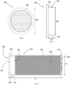
- Prefilter 100 is visible in Figures 1a, 1b , 6 And 7 .
- the prefilter 100 may comprise a conduit 101 divided into a first portion 110 and a second portion 120.
- the conduit 101 comprises a first and a second mouth.
- a first filtration material 130 is housed in the conduit 101 of the prefilter 100, preferably in the second portion 120 of the conduit 101.
- the portions 110 and 120 of the conduit of the prefilter preferably have a substantially cylindrical shape.
- the portions 110 and 120 of the conduit of the prefilter may not have an identical diameter.
- the first mouth through which the contaminated water is intended to enter the prefilter comprises a diameter Dpf1 smaller than the diameter Dpf2 of the second mouth through which the contaminated water is intended to pass from the prefilter 100 to the filter 400.
- the connection of the prefilter 100 and the filter 400 is made at the second mouth of the prefilter 100.
- the inner diameter of the second part 120 of the prefilter 100 may be substantially equal to the inner diameter of the filter 400.
- the inner diameter of the second part of the prefilter 120 may be between 50 mm and 150 mm and is preferably equal to 90 mm, for example to within plus or minus 10 mm.
- the outer diameter Dpf2 of the second part of the prefilter 120 may be between 55 mm and 145 mm and is preferably equal to 108 mm, for example to within plus or minus 10 mm.
- the outer diameter Dpf2 of the second part of the prefilter 120 is substantially equal to the diameter Df of the conduit 410 of the filter 400.
- the second mouth of the second part of the prefilter 120 is configured to be able to abut the first grid 300 of the filter, preferably flush with the outer periphery of the second shoulder 303.
- the thickness Epf of the prefilter 100, and in particular of its second part 120 can be between 3 mm and 20 mm and is preferably equal to 4 mm, for example to within plus or minus 2 mm.
- the thickness Epf of the conduit of the prefilter 100 is determined with respect to two criteria. It must provide satisfactory resistance to pressure and offer a long service life to the pre-filter 100. In fact, this part is intended to be changed less regularly than the filter 400.
- the total length Lpf of the pre-filter can be between 70 mm and 160 mm and is preferably equal to 122 mm, for example. example to within plus or minus 20 mm.
- a first thread 111 is present on the outer surface of the second part 120 of the prefilter.
- the first thread 111 present on the second part 120 of the prefilter can extend from the second mouth over a length which can be between 10 mm and 50 mm, and preferably equal to 20 mm, for example to within plus or minus 5 mm.
- the second part 120 of the prefilter preferably has an excess thickness relative to the thickness Epf of the remainder of the conduit 101 of the prefilter 100.
- the first thread 111 can have a pitch between 0.25 mm and 6 mm and preferably equal to 2 mm, for example to within plus or minus 0.5 mm.
- the first thread 111 is configured to cooperate with the assembly ring 200.
- the prefilter 100 is based on one of a polyamide and a polyoxymethylene (or POM).
- the first filtration material 130 is configured to filter the water so as to retain macroscopic sediments.
- This first filtration material 130 may be a foam or any other material allowing such filtration.
- the first filtration material 130 is removable from the prefilter 100. Its cleaning and replacement are facilitated, which allows simplified reuse and recycling, respectively. Thus, only the first filtration material 130 can be changed, even on site, which reduces maintenance costs.
- FIG. 1a represents in particular the prefilter 100 in a first embodiment.
- the prefilter 100 is produced by machining.
- FIG. 1b represents another embodiment of the prefilter 100.
- the prefilter 100 is produced by injection.
- the method of realization of the figure 1b is preferential over the embodiment illustrated in the figure 1a in particular because it makes it possible to further reduce the material required for the manufacture and use of the prefilter 100.
- the second part 120 of the conduit 101 has an excess thickness at the location of the first thread 111.
- the assembly ring may comprise a first part 220 and a second part 210.
- a first shoulder 212 may be provided between the first and second parts 210; 220 of the ring.
- the second part 210 of the ring 200 has an inner diameter Dba1 which can be between 55 mm and 145 mm and is preferably equal to 108 mm.
- the inner diameter Dba1 is preferably substantially equal to the outer diameter Dpf2 of the second part 120 of the prefilter 100.
- the assembly ring 200 has an outer diameter between 60 mm and 180 mm, and is preferably equal to 118 mm, for example to within plus or minus 20 mm.
- the second part 210 of the ring 200 comprises a second thread 211 configured to cooperate with the first thread 111 present on the second part 120 of the prefilter 100.
- the first part 220 of the ring 200 has an inner diameter Dba2 which can be between 51 mm and 151 mm and preferably 91 mm, for example to within plus or minus 10 mm. It is preferably greater than that of the outer diameter of the filter so that the first part 220 of the ring 200 constitutes a slide in which the conduit 410 of the filter 400 is able to slide tightly. Thus, only the inner diameter of the assembly ring varies between the first part 220 of the ring 200 and the second part 210 of the ring 200.
- the outer diameter can remain constant.
- the outer diameter of the ring 200 may have a variation resulting in the presence of a shoulder on the outer contour of the ring.
- This shoulder is for example offset, in the direction of a length Lba of the assembly ring 200, by a distance of between 2 mm and 10 mm, preferably equal to 7.5 mm, to within plus or minus 2 mm, from the first shoulder 212 formed on the inner circumference of the ring.
- the wall thickness Eba1 of the second part 210 of the ring 200 may be between 3 mm and 20 mm and is preferably equal to 5 mm, for example to within plus or minus 2 mm.
- the wall thickness Eba2 of the first part 220 of the ring 200 may be between 5 mm and 20 mm and is preferably equal to 10 mm, for example to within plus or minus 2 mm.
- the wall thickness Eba2 of the first part 220 of the ring 200 may be between 3 mm and 20 mm and is preferably equal to 4 mm, for example to within plus or minus 1 mm.
- the thickness of the walls of the assembly ring 200 is determined according to the desired rigidity and pressure resistance achieved by the assembly.
- the length Lba of the assembly ring 200 may be between 50 mm and 100 mm and is preferably equal to 75 mm, for example plus or minus 10 mm near.
- the length of the first part 220 of the ring 200 is preferably greater than the length of the second part 210 of the ring 200. According to the invention, the length of the first part 220 of the ring 200 is at least twice the length of the second part 210 of the ring 200.
- the assembly ring 200 is preferably made of the same material as the prefilter 100, or of a different material, but chosen from a polyamide and a polyoxymethylene (or POM).
- FIG. 2a represents in particular the ring 200 in a first embodiment.
- the ring 200 is produced by machining.
- FIG. 2b represents another embodiment of the ring 200.
- the ring 200 is made by injection.
- the method of realization of the figure 2b is preferential over the embodiment illustrated in the Figure 2a in particular because it makes it possible to further reduce the material required for the manufacture and use of the ring 200, in particular by reducing the thickness of the first part 220 of the ring 200.
- the second part 210 of the ring 200 has an excess thickness of material at the location of the second thread 211.
- the prefilter 400 is first inserted into the assembly ring 200. More particularly, the filter 400 is inserted by its second end 420 through the second part 210 of the assembly ring 200. As mentioned above, the first part 220 of the ring 200 forms a slide configured to guide the sliding of the filter 400. The sliding of the filter 400 in the ring 200 is limited by the stop of the second shoulder 303 of the first grid 300 of the filter 400 on the first shoulder 212 of the ring 200. At this stage, a part of the second part 210 of the ring 200 extends beyond the first grid 300 of the filter 400; this part at least partly supports the first fixing element. As previously mentioned, the first fastening element is configured and intended to cooperate with the second fastening element of the prefilter.
- the first fastening element takes the form of a tapping made in the second part 210 of the ring 200 and the second fastening element takes the form of a first corresponding thread 111 made on the periphery of the second end of the prefilter 100.
- the first fixing element takes the form of a tapping made in the second part 210 of the ring 200 and the second fastening element takes the form of a first corresponding thread 111 made on the periphery of the second end of the prefilter 100.
- the pressure with which the prefilter 100 presses the first and second shoulders together is advantageously adjustable, and more particularly proportional to the screwing force between the prefilter 300 and the assembly ring 200.
- This pressure causes an inverse proportional reaction which leads to friction between the tapping of the ring 200 and the thread of the prefilter 100, to prevent any accidental disassembly of the cartridge 1.
- the screwing fixing is particularly advantageous, because it allows rapid assembly and disassembly, while allowing significant pressure resistance.
- the first shoulder 212 therefore abuts the second shoulder 303 of the first grid 300.
- the first part 220 of the ring 200 is opposite the conduit 410 of the filter 400.
- the second part 210 of the ring 200 is at least partly opposite the periphery of the second end of the prefilter 100.
- the length of the first part 220 of the ring 200 opposite the filter 400 allows reinforcement of the structure as a whole.
- the first portion 220 of the ring 200 has an inner diameter corresponding substantially to the outer diameter of the conduit 410 of the filter 400.
- the length of the first portion 220 of the ring 200 extends opposite a portion of the conduit 410 of the filter 400, and more particularly, over a significant overlap and contact length Lba2, for example between 3 and 20%, preferably equal to 4.6%, to within plus or minus 1%, relative to the length Lf of the conduit 410 of the filter 400.
- the first portion 220 of the ring 200 may have a significant thickness Eba2, for example greater by a ratio between 10 and 200%, preferably greater by 43%, to within plus or minus 5%, relative to the thickness of the wall of the conduit 410 of the filter 400. 400.
- the first part 220 of the ring 200 thus contributes to the pressure resistance that the filter 400 must withstand.
- the thickness of the wall of the conduit 410 of the filter 400 can be reduced, because it is the overall thickness of the cartridge 1, namely the thickness of the wall of the conduit 410 of the filter 400 plus the thickness Eba2 of the first part 220 of the ring 200 which makes it possible to determine the resistance of the cartridge 1 at least over the covering and contact length Lba2 of the filter 400 by the ring 200.
- the greater the covering and contact length Lba2 the more the thickness of the conduit 410 of the filter 400 can be reduced.
- the greater the thickness Eba2 of the first part 220 of the ring 200 the more the thickness of the conduit 410 of the filter 400 can be reduced.
- the resistance of the cartridge is greatly improved by allowing a reduction in the mass of the conduit 410 of the filter 400.
- the mass of waste due to changing the filter 400 is greatly limited. This allows on the one hand savings in maintenance costs (the mass of products to be changed regularly is reduced, therefore the production costs are controlled), and on the other hand to limit the ecological impact of a regular change of filter 400 due to the reduction in the material used to produce the filter 400 and therefore a control of the mass of waste to be recycled and the associated costs.
- the assembly ring 200 is removable from the filter 400 and the pre-filter 100 and cleanable in order to extend its service life as much as possible. What is more, in the event of changing the filter 400 and/or the pre-filter 300, the assembly ring 200 can be reused. This further limits waste.
- the filter 400 represents less than 50% of the total mass of the filtration cartridge 1.
- the remainder of the cartridge 1, namely the assembly ring 200 and the prefilter 300, can be cleaned for rapid reuse. These operations can be carried out on site since the filtered hydrocarbons are essentially confined in the filter 400 to be replaced.
- the fixing of the first and/or second grid 300 on the duct 410 can be done by clipping.
- the first and second fixing elements can respectively comprise a clip and a notch.
- the second shoulder 303 may not be carried by the first grid 300 of the filter 400. It may for example be carried directly by the conduit 410 of the filter 400.
- the first grid 300 may have an external diameter substantially equal to the diameter of the conduit 410 excluding the shoulder 303.
- the sections of the prefilter, ring and filter are preferably circular, but can also be square, rectangular, oval, etc.
- the invention is particularly applicable in a system for recovering hydrocarbons from at least one electrical transformer comprising at least one filtration cartridge 1 as described above.
- the invention also finds application in the filtration of runoff water from parking areas, service stations, motorways, tunnels, airports, etc.
- This runoff water is currently best treated by settling in basins without filtration or by cleaning with a cleaner. high pressure with possible recovery for transfer to the destruction and/or treatment site.
- the invention is advantageously adaptable to the above-mentioned settling basins, downstream, but also upstream, of said basins.
- the invention is also not limited to the filtration of rainwater, but extends to the filtration of seawater, in particular polluted with hydrocarbons by degassing or navigation accidents.
- Each of the rigid parts (excluding filtration materials) constituting the cartridge 1 can be manufactured by machining or by injection.
- the parts obtained by injection easily take the form of those illustrated in the Figures 1b And 2b .
- machining it will be easier and less expensive to manufacture a prefilter and an assembly ring having constant external contours, as shown in the Figures 1a And 2a respectively.
- These two manufacturing techniques make it possible to comply with the specifications in terms of resistance of the manufactured part to the stresses to which it will be subjected and in terms of reliability of assembly with the other parts of the cartridge 1, but manufacturing by injection is preferred for reasons of manufacturing cost.
- the total mass of the filtration cartridge whose parts are obtained by machining is substantially equal to 1.4 kg, whereas the total mass of the filtration cartridge whose parts are obtained by injection can be reduced to less than 1 kg.
Landscapes
- Chemical & Material Sciences (AREA)
- Chemical Kinetics & Catalysis (AREA)
- Life Sciences & Earth Sciences (AREA)
- Hydrology & Water Resources (AREA)
- Engineering & Computer Science (AREA)
- Environmental & Geological Engineering (AREA)
- Water Supply & Treatment (AREA)
- Organic Chemistry (AREA)
- Water Treatment By Sorption (AREA)
- Filtering Materials (AREA)
Claims (11)
- Filterkartusche (1) für durch Kohlenwasserstoff verunreinigtes Wasser, die mindestens Folgendes umfasst:- einen Vorfilter (100), der mindestens einen Kanal (101) umfasst, der so konfiguriert ist, dass er ein erstes Filtermaterial (130) in sich aufnimmt,- einen Filter (400), der mindestens einen Kanal (410) umfasst, der so konfiguriert ist, dass er mindestens ein zweites Filtermaterial (430) in sich aufnimmt, und- ein Befestigungssystem, das so konfiguriert ist, dass es den Kanal (410) des Filters (400) und den Kanal (101) des Vorfilters (100) zusammenhält,wobei das Befestigungssystem mindestens einen Montagering (200) umfasst, der den Kanal (410) des Filters (400) und den Kanal (101) des Vorfilters (100) im Verhältnis zueinander abnehmbar zusammenhält,die Kartusche (1) drei abnehmbare Teile umfasst: den Filter (400), den Vorfilter (100) und den Montagering (200),die Kanäle des Filters und des Vorfilters nebeneinander befestigt werden,der Montagering (200) einen ersten Teil (220) aufweist, der so konfiguriert ist, dass er sich gegenüber eines Teils des Kanals (410) des Filters (400) erstreckt, und einen zweiten Teil (210), der so konfiguriert ist, dass er sich gegenüber eines Teils des Kanals (101) des Vorfilters (100) erstreckt,der erste Teil (220) des Rings (200) eine Länge Lba2 aufweist, über die der erste Teil (220) den Kanal (410) der Kartusche (400) abdeckt und berührt, unddie Länge Lba2 des ersten Teils (220) des Montagerings (200) größer ist als eine Länge Lba1 des zweiten Teils (210) des Montagerings (200),wobei die Kartusche dadurch gekennzeichnet ist, dass:die Länge Lba2 des ersten Teils (220) des Montagerings (200) mindestens zweimal größer ist als die Länge Lba1 des zweiten Teils (210) des Montagerings (200),die Länge Lba2, über die der erste Teil (220) den Kanal (410) des Filters (400) abdeckt und berührt, und die Dicke Eba2 des ersten Teils (220) des Rings (200) auf der Länge Lba2 so konfiguriert sind, dass sie dem Druck standhalten, der mindestens vom verunreinigten Wasser während seines Durchgangs durch den Kanal (410) ausgeübt wird.
- Filterkartusche (1) nach dem vorhergehenden Anspruch, wobei der Montagering (200) eine erste Schulter (212) und ein erstes Befestigungselement umfasst, wobei einer von dem Filter (400) und dem Vorfilter (100) eine zweite Schulter (303) umfasst, die so konfiguriert ist, dass sie mit der ersten Schulter (212) zusammenwirkt, und wobei der andere von dem Filter (400) und dem Vorfilter (100) ein zweites Befestigungselement umfasst, das so konfiguriert ist, dass es mit dem ersten Befestigungselement des Montagerings (200) zusammenwirkt, wobei das Zusammenwirken zwischen dem ersten und dem zweiten Befestigungselement so parametrisiert ist, dass die erste und die zweite Schulter aneinander anliegen.
- Filterkartusche (1) nach dem vorhergehenden Anspruch, wobei das erste und das zweite Befestigungselement so einstellbar sind, dass die erste und die zweite Schulter mit einer einstellbaren Stützkraft aneinander anliegend gehalten werden, wobei vorzugsweise eines von dem ersten Befestigungselement und dem zweiten Befestigungselement ein Innengewinde umfasst und das andere von dem ersten Befestigungselement und dem zweiten Befestigungselement ein Außengewinde umfasst.
- Filterkartusche (1) nach einem der beiden vorhergehenden Ansprüche, wobei sich die zweite Schulter von der Kontur eines ersten Gitters (300) erstreckt, das so konfiguriert ist, dass es das Ende eines von dem Kanal (410) des Filters (400) und dem Kanal (101) des Vorfilters (100) mindestens für Wasser durchlässig verschließt, und das den Kanal (410) des Filters (400) und den Kanal (101) des Vorfilters (100) zusammenhalten soll.
- Filterkartusche (1) nach Anspruch 1, wobei die Dicke des Kanals (410) des Filters (400) umso kleiner ist, je größer mindestens eine von der Länge Lba2 und der Dicke Eba2 ist.
- Filterkartusche (1) nach einem der vorhergehenden Ansprüche, wobei die Länge Lba2, über die der erste Teil (220) des Montagerings (200) den Kanal (410) des Filters (400) abdeckt und berührt, zwischen 3 und 20 %, plus/minus 1 %, der Länge Lf des Kanals (410) des Filters (400) beträgt.
- Filterkartusche (1) nach einem der vorhergehenden Ansprüche, wobei die Dicke Eba2 des ersten Teils (220) des Rings (200) im Verhältnis zur Dicke der Wand des Kanals (410) des Filters (400) um ein Verhältnis zwischen 10 und 200 %, plus/minus 5 %, größer ist.
- Filterkartusche (1) nach einem der vorhergehenden Ansprüche, wobei der Kanal (410) des Filters (400) ferner so konfiguriert ist, dass er das zweite Filtermaterial (430) derart in sich aufnimmt, dass er das zweite Filtermaterial (430) im Inneren des Filters eindämmt.
- Filterkartusche (1) nach einem der vorhergehenden Ansprüche, wobei der Montagering (200) im Wesentlichen die Form eines Kanals aufweist, dessen Innendurchmesser in Abhängigkeit von dem Außendurchmesser Dpf2 des Vorfilters (100) und dem Durchmesser der Schulter des Filters (400) bestimmt wird, wobei sich die erste Schulter (212) zum Beispiel von der Innenfläche des Kanals erstreckt, die der Montagering (200) im Wesentlichen bildet.
- Filterkartusche (1) nach einem der vorhergehenden Ansprüche, wobei die Summe der Masse des Vorfilters (100) und der Masse des Montagerings (200) größer als 50 %, vorzugsweise größer als 60 %, der Gesamtmasse der Filterkartusche (1) ist.
- System zur Rückgewinnung von Kohlenwasserstoff aus mindestens einem elektrischen Transformator, das mindestens eine Filterkartusche (1) nach einem der vorhergehenden Ansprüche umfasst.
Applications Claiming Priority (2)
| Application Number | Priority Date | Filing Date | Title |
|---|---|---|---|
| FR1760697A FR3073427B1 (fr) | 2017-11-14 | 2017-11-14 | Cartouche de filtration d'eau contaminee |
| PCT/EP2018/080453 WO2019096650A1 (fr) | 2017-11-14 | 2018-11-07 | Cartouche de filtration d'eau contaminée |
Publications (3)
| Publication Number | Publication Date |
|---|---|
| EP3710131A1 EP3710131A1 (de) | 2020-09-23 |
| EP3710131C0 EP3710131C0 (de) | 2024-09-25 |
| EP3710131B1 true EP3710131B1 (de) | 2024-09-25 |
Family
ID=61003190
Family Applications (1)
| Application Number | Title | Priority Date | Filing Date |
|---|---|---|---|
| EP18796068.7A Active EP3710131B1 (de) | 2017-11-14 | 2018-11-07 | Filterkartusche für kontaminiertes wasser |
Country Status (5)
| Country | Link |
|---|---|
| EP (1) | EP3710131B1 (de) |
| AU (1) | AU2018366953B2 (de) |
| ES (1) | ES2997375T3 (de) |
| FR (1) | FR3073427B1 (de) |
| WO (1) | WO2019096650A1 (de) |
Families Citing this family (2)
| Publication number | Priority date | Publication date | Assignee | Title |
|---|---|---|---|---|
| CN112221248A (zh) * | 2020-10-16 | 2021-01-15 | 北京怡盛原环保科技有限公司 | 一种具有多重过滤结构的净水器 |
| CN114108781A (zh) * | 2021-11-26 | 2022-03-01 | 内蒙古电力(集团)有限责任公司内蒙古电力经济技术研究院分公司 | 一种110kV变电站油水分离式变压器事故油池 |
Citations (3)
| Publication number | Priority date | Publication date | Assignee | Title |
|---|---|---|---|---|
| US5922199A (en) * | 1993-09-15 | 1999-07-13 | Parker Hannifin Corporation | Double pass fuel filter assembly |
| US6210577B1 (en) * | 1997-04-29 | 2001-04-03 | Robert Guy Garber | Multiple cartridge housing assembly for the high purity filtration of liquids |
| US20040154975A1 (en) * | 2001-06-12 | 2004-08-12 | Giorgio Girondi | Liquid filter for vehicle internal combustion engines |
Family Cites Families (6)
| Publication number | Priority date | Publication date | Assignee | Title |
|---|---|---|---|---|
| JP2007528235A (ja) * | 2003-07-19 | 2007-10-11 | 株式会社インフィニティ・ジャパン | 芳香水およびペットのための機能性溶液を製造する装置 |
| WO2006084100A2 (en) | 2005-02-04 | 2006-08-10 | Imbibitive Technologies Corporation | Drain system |
| US20090008318A1 (en) * | 2006-12-04 | 2009-01-08 | Prismedical Corporation | Modular Water Purification and Delivery System |
| FR2948647B1 (fr) | 2009-07-30 | 2011-08-26 | Gmt | Dispositif d'extinction rapide et naturelle pour fosses d'extinction et bacs de retention anti-feu d'huile inflammable, notamment de transformateurs electriques |
| CN201906509U (zh) * | 2010-12-17 | 2011-07-27 | 厦门市易洁卫浴有限公司 | 多级串联复合滤芯 |
| DE102015225408A1 (de) * | 2015-12-16 | 2017-06-22 | Orben Wasseraufbereitung Gmbh & Co. Kg | Filterkartusche |
-
2017
- 2017-11-14 FR FR1760697A patent/FR3073427B1/fr active Active
-
2018
- 2018-11-07 ES ES18796068T patent/ES2997375T3/es active Active
- 2018-11-07 EP EP18796068.7A patent/EP3710131B1/de active Active
- 2018-11-07 WO PCT/EP2018/080453 patent/WO2019096650A1/fr not_active Ceased
- 2018-11-07 AU AU2018366953A patent/AU2018366953B2/en active Active
Patent Citations (3)
| Publication number | Priority date | Publication date | Assignee | Title |
|---|---|---|---|---|
| US5922199A (en) * | 1993-09-15 | 1999-07-13 | Parker Hannifin Corporation | Double pass fuel filter assembly |
| US6210577B1 (en) * | 1997-04-29 | 2001-04-03 | Robert Guy Garber | Multiple cartridge housing assembly for the high purity filtration of liquids |
| US20040154975A1 (en) * | 2001-06-12 | 2004-08-12 | Giorgio Girondi | Liquid filter for vehicle internal combustion engines |
Also Published As
| Publication number | Publication date |
|---|---|
| AU2018366953A1 (en) | 2020-07-02 |
| EP3710131C0 (de) | 2024-09-25 |
| FR3073427B1 (fr) | 2023-04-07 |
| FR3073427A1 (fr) | 2019-05-17 |
| EP3710131A1 (de) | 2020-09-23 |
| ES2997375T3 (en) | 2025-02-17 |
| BR112020009546A2 (pt) | 2020-10-13 |
| AU2018366953B2 (en) | 2024-08-01 |
| WO2019096650A1 (fr) | 2019-05-23 |
Similar Documents
| Publication | Publication Date | Title |
|---|---|---|
| EP3710131B1 (de) | Filterkartusche für kontaminiertes wasser | |
| EP2569080B1 (de) | Wasserfiltrierungsmodul sowie verfahren zur seiner herstellung und montage | |
| EP0975411B1 (de) | Filter und filterkartusche mit äusserem anschlag für die filtration von flüssigkeiten, die in einem motor oder einer hydraulik zirkulieren | |
| FR3057176A1 (fr) | Ensemble de filtrage comportant une cartouche de filtration | |
| FR2851634A1 (fr) | Pince de raccord et structure de raccordement de raccord destinees a verifier le raccordement complet entre un raccord et un tuyau | |
| FR2796567A1 (fr) | Filtre pour fluides,pourvu de moyens de filtration interchangeables | |
| WO2020020794A1 (fr) | Dispositif de filtration pour un reacteur a co-courant descendant de fluide | |
| FR2957999A1 (fr) | Piston avec un conduit sous joint | |
| FR3057469A1 (fr) | Cartouche de filtration a event integre dans le flasque superieur et systeme de filtration correspondant. | |
| FR2946062A1 (fr) | Separateur de matieres, notamment pour poste de relevage d'eaux usees, et poste de relevage en comportant application | |
| EP3068514A1 (de) | Filtersystem für einen geschlossenen hydraulikkreis mit einem manschettenständer über dem stopfen für dessen demontage | |
| FR3129848A1 (fr) | Cartouche filtrante à bouchon décentré et Filtre pour liquide de moteur à combustion incluant la cartouche | |
| EP2020465B1 (de) | Bypass-Vorrichtung für Kohlenwasserstoffseparator, der für die Aufbereitung von Oberflächenwasser bestimmt ist | |
| EP3212302B1 (de) | Vorrichtung zur filtrierung von walzöl | |
| EP3368186B1 (de) | Verbindung mit sperrschnurelement | |
| WO2012066202A1 (fr) | Dispositif de réparation et d'aménagement d'une piscine a paroi en béton, installation et procède afférents | |
| FR2949457A1 (fr) | Cartouche pour un dispositif de traitement d'eau | |
| CA2495995C (fr) | Element male ou femelle de raccord rapide et raccord rapide comprenant un tel element | |
| FR2949351A1 (fr) | Dispositif de filtration et installation de recuperation des eaux pluviales equipees d'un tel dispositif | |
| EP3932873A1 (de) | Vorrichtung zur hochdruckinjektion eines abwassers | |
| KR101056288B1 (ko) | 일체형 결합판을 이용하여 홀더로 체결하는 일체형 관 | |
| EP0670464A1 (de) | Vorrichtung zum Druckspritzen eines Fluidums in einem Plattenstapel eines Wärmetauschers | |
| FR2995757A1 (fr) | Distributeur d'irrigation a debit autoregule et son utilisation | |
| EP3031780A1 (de) | Verfahren zum auffangen von eisenhaltigen schlämmen in einem hydraulikkreislauf | |
| FR3138460A1 (fr) | Boite de reservation pourvue d’une partie aimantee |
Legal Events
| Date | Code | Title | Description |
|---|---|---|---|
| STAA | Information on the status of an ep patent application or granted ep patent |
Free format text: STATUS: UNKNOWN |
|
| STAA | Information on the status of an ep patent application or granted ep patent |
Free format text: STATUS: THE INTERNATIONAL PUBLICATION HAS BEEN MADE |
|
| PUAI | Public reference made under article 153(3) epc to a published international application that has entered the european phase |
Free format text: ORIGINAL CODE: 0009012 |
|
| STAA | Information on the status of an ep patent application or granted ep patent |
Free format text: STATUS: REQUEST FOR EXAMINATION WAS MADE |
|
| 17P | Request for examination filed |
Effective date: 20200611 |
|
| AK | Designated contracting states |
Kind code of ref document: A1 Designated state(s): AL AT BE BG CH CY CZ DE DK EE ES FI FR GB GR HR HU IE IS IT LI LT LU LV MC MK MT NL NO PL PT RO RS SE SI SK SM TR |
|
| AX | Request for extension of the european patent |
Extension state: BA ME |
|
| DAV | Request for validation of the european patent (deleted) | ||
| DAX | Request for extension of the european patent (deleted) | ||
| STAA | Information on the status of an ep patent application or granted ep patent |
Free format text: STATUS: EXAMINATION IS IN PROGRESS |
|
| 17Q | First examination report despatched |
Effective date: 20210526 |
|
| GRAP | Despatch of communication of intention to grant a patent |
Free format text: ORIGINAL CODE: EPIDOSNIGR1 |
|
| STAA | Information on the status of an ep patent application or granted ep patent |
Free format text: STATUS: GRANT OF PATENT IS INTENDED |
|
| INTG | Intention to grant announced |
Effective date: 20240425 |
|
| GRAS | Grant fee paid |
Free format text: ORIGINAL CODE: EPIDOSNIGR3 |
|
| GRAA | (expected) grant |
Free format text: ORIGINAL CODE: 0009210 |
|
| STAA | Information on the status of an ep patent application or granted ep patent |
Free format text: STATUS: THE PATENT HAS BEEN GRANTED |
|
| AK | Designated contracting states |
Kind code of ref document: B1 Designated state(s): AL AT BE BG CH CY CZ DE DK EE ES FI FR GB GR HR HU IE IS IT LI LT LU LV MC MK MT NL NO PL PT RO RS SE SI SK SM TR |
|
| REG | Reference to a national code |
Ref country code: GB Ref legal event code: FG4D Free format text: NOT ENGLISH |
|
| REG | Reference to a national code |
Ref country code: CH Ref legal event code: EP |
|
| REG | Reference to a national code |
Ref country code: DE Ref legal event code: R096 Ref document number: 602018074750 Country of ref document: DE |
|
| REG | Reference to a national code |
Ref country code: IE Ref legal event code: FG4D Free format text: LANGUAGE OF EP DOCUMENT: FRENCH |
|
| U01 | Request for unitary effect filed |
Effective date: 20241021 |
|
| U07 | Unitary effect registered |
Designated state(s): AT BE BG DE DK EE FI FR IT LT LU LV MT NL PT RO SE SI Effective date: 20241104 |
|
| U20 | Renewal fee for the european patent with unitary effect paid |
Year of fee payment: 7 Effective date: 20241114 |
|
| PG25 | Lapsed in a contracting state [announced via postgrant information from national office to epo] |
Ref country code: NO Free format text: LAPSE BECAUSE OF FAILURE TO SUBMIT A TRANSLATION OF THE DESCRIPTION OR TO PAY THE FEE WITHIN THE PRESCRIBED TIME-LIMIT Effective date: 20241225 |
|
| PG25 | Lapsed in a contracting state [announced via postgrant information from national office to epo] |
Ref country code: GR Free format text: LAPSE BECAUSE OF FAILURE TO SUBMIT A TRANSLATION OF THE DESCRIPTION OR TO PAY THE FEE WITHIN THE PRESCRIBED TIME-LIMIT Effective date: 20241226 |
|
| PG25 | Lapsed in a contracting state [announced via postgrant information from national office to epo] |
Ref country code: RS Free format text: LAPSE BECAUSE OF FAILURE TO SUBMIT A TRANSLATION OF THE DESCRIPTION OR TO PAY THE FEE WITHIN THE PRESCRIBED TIME-LIMIT Effective date: 20241225 |
|
| PG25 | Lapsed in a contracting state [announced via postgrant information from national office to epo] |
Ref country code: RS Free format text: LAPSE BECAUSE OF FAILURE TO SUBMIT A TRANSLATION OF THE DESCRIPTION OR TO PAY THE FEE WITHIN THE PRESCRIBED TIME-LIMIT Effective date: 20241225 Ref country code: NO Free format text: LAPSE BECAUSE OF FAILURE TO SUBMIT A TRANSLATION OF THE DESCRIPTION OR TO PAY THE FEE WITHIN THE PRESCRIBED TIME-LIMIT Effective date: 20241225 Ref country code: GR Free format text: LAPSE BECAUSE OF FAILURE TO SUBMIT A TRANSLATION OF THE DESCRIPTION OR TO PAY THE FEE WITHIN THE PRESCRIBED TIME-LIMIT Effective date: 20241226 |
|
| REG | Reference to a national code |
Ref country code: ES Ref legal event code: FG2A Ref document number: 2997375 Country of ref document: ES Kind code of ref document: T3 Effective date: 20250217 |
|
| PG25 | Lapsed in a contracting state [announced via postgrant information from national office to epo] |
Ref country code: IS Free format text: LAPSE BECAUSE OF FAILURE TO SUBMIT A TRANSLATION OF THE DESCRIPTION OR TO PAY THE FEE WITHIN THE PRESCRIBED TIME-LIMIT Effective date: 20250125 |
|
| PG25 | Lapsed in a contracting state [announced via postgrant information from national office to epo] |
Ref country code: SM Free format text: LAPSE BECAUSE OF FAILURE TO SUBMIT A TRANSLATION OF THE DESCRIPTION OR TO PAY THE FEE WITHIN THE PRESCRIBED TIME-LIMIT Effective date: 20240925 |
|
| PG25 | Lapsed in a contracting state [announced via postgrant information from national office to epo] |
Ref country code: PL Free format text: LAPSE BECAUSE OF FAILURE TO SUBMIT A TRANSLATION OF THE DESCRIPTION OR TO PAY THE FEE WITHIN THE PRESCRIBED TIME-LIMIT Effective date: 20240925 |
|
| PG25 | Lapsed in a contracting state [announced via postgrant information from national office to epo] |
Ref country code: SK Free format text: LAPSE BECAUSE OF FAILURE TO SUBMIT A TRANSLATION OF THE DESCRIPTION OR TO PAY THE FEE WITHIN THE PRESCRIBED TIME-LIMIT Effective date: 20240925 |
|
| REG | Reference to a national code |
Ref country code: CH Ref legal event code: PL |
|
| PG25 | Lapsed in a contracting state [announced via postgrant information from national office to epo] |
Ref country code: MC Free format text: LAPSE BECAUSE OF FAILURE TO SUBMIT A TRANSLATION OF THE DESCRIPTION OR TO PAY THE FEE WITHIN THE PRESCRIBED TIME-LIMIT Effective date: 20240925 |
|
| REG | Reference to a national code |
Ref country code: CH Ref legal event code: PL |
|
| PG25 | Lapsed in a contracting state [announced via postgrant information from national office to epo] |
Ref country code: CH Free format text: LAPSE BECAUSE OF NON-PAYMENT OF DUE FEES Effective date: 20241130 |
|
| PLBE | No opposition filed within time limit |
Free format text: ORIGINAL CODE: 0009261 |
|
| STAA | Information on the status of an ep patent application or granted ep patent |
Free format text: STATUS: NO OPPOSITION FILED WITHIN TIME LIMIT |
|
| 26N | No opposition filed |
Effective date: 20250626 |
|
| U20 | Renewal fee for the european patent with unitary effect paid |
Year of fee payment: 8 Effective date: 20251120 |
|
| PGFP | Annual fee paid to national office [announced via postgrant information from national office to epo] |
Ref country code: GB Payment date: 20251126 Year of fee payment: 8 |
|
| PG25 | Lapsed in a contracting state [announced via postgrant information from national office to epo] |
Ref country code: HR Free format text: LAPSE BECAUSE OF FAILURE TO SUBMIT A TRANSLATION OF THE DESCRIPTION OR TO PAY THE FEE WITHIN THE PRESCRIBED TIME-LIMIT Effective date: 20240925 |
|
| PGFP | Annual fee paid to national office [announced via postgrant information from national office to epo] |
Ref country code: IE Payment date: 20251021 Year of fee payment: 8 Ref country code: CZ Payment date: 20251107 Year of fee payment: 8 |
|
| PGFP | Annual fee paid to national office [announced via postgrant information from national office to epo] |
Ref country code: ES Payment date: 20251210 Year of fee payment: 8 |
|
| PG25 | Lapsed in a contracting state [announced via postgrant information from national office to epo] |
Ref country code: HU Free format text: LAPSE BECAUSE OF FAILURE TO SUBMIT A TRANSLATION OF THE DESCRIPTION OR TO PAY THE FEE WITHIN THE PRESCRIBED TIME-LIMIT; INVALID AB INITIO Effective date: 20181107 |
|
| PG25 | Lapsed in a contracting state [announced via postgrant information from national office to epo] |
Ref country code: CY Free format text: LAPSE BECAUSE OF FAILURE TO SUBMIT A TRANSLATION OF THE DESCRIPTION OR TO PAY THE FEE WITHIN THE PRESCRIBED TIME-LIMIT; INVALID AB INITIO Effective date: 20181107 |