EP3709795B1 - Eierträger und vorrichtung zur handhabung von eiern - Google Patents
Eierträger und vorrichtung zur handhabung von eiern Download PDFInfo
- Publication number
- EP3709795B1 EP3709795B1 EP17811452.6A EP17811452A EP3709795B1 EP 3709795 B1 EP3709795 B1 EP 3709795B1 EP 17811452 A EP17811452 A EP 17811452A EP 3709795 B1 EP3709795 B1 EP 3709795B1
- Authority
- EP
- European Patent Office
- Prior art keywords
- egg
- members
- carrier
- operating
- clamping
- Prior art date
- Legal status (The legal status is an assumption and is not a legal conclusion. Google has not performed a legal analysis and makes no representation as to the accuracy of the status listed.)
- Active
Links
Images


Classifications
-
- A—HUMAN NECESSITIES
- A01—AGRICULTURE; FORESTRY; ANIMAL HUSBANDRY; HUNTING; TRAPPING; FISHING
- A01K—ANIMAL HUSBANDRY; AVICULTURE; APICULTURE; PISCICULTURE; FISHING; REARING OR BREEDING ANIMALS, NOT OTHERWISE PROVIDED FOR; NEW BREEDS OF ANIMALS
- A01K43/00—Testing, sorting or cleaning eggs ; Conveying devices ; Pick-up devices
-
- A—HUMAN NECESSITIES
- A01—AGRICULTURE; FORESTRY; ANIMAL HUSBANDRY; HUNTING; TRAPPING; FISHING
- A01K—ANIMAL HUSBANDRY; AVICULTURE; APICULTURE; PISCICULTURE; FISHING; REARING OR BREEDING ANIMALS, NOT OTHERWISE PROVIDED FOR; NEW BREEDS OF ANIMALS
- A01K45/00—Other aviculture appliances, e.g. devices for determining whether a bird is about to lay
- A01K45/007—Injecting or otherwise treating hatching eggs
-
- B—PERFORMING OPERATIONS; TRANSPORTING
- B65—CONVEYING; PACKING; STORING; HANDLING THIN OR FILAMENTARY MATERIAL
- B65G—TRANSPORT OR STORAGE DEVICES, e.g. CONVEYORS FOR LOADING OR TIPPING, SHOP CONVEYOR SYSTEMS OR PNEUMATIC TUBE CONVEYORS
- B65G47/00—Article or material-handling devices associated with conveyors; Methods employing such devices
- B65G47/74—Feeding, transfer, or discharging devices of particular kinds or types
- B65G47/94—Devices for flexing or tilting travelling structures; Throw-off carriages
-
- B—PERFORMING OPERATIONS; TRANSPORTING
- B65—CONVEYING; PACKING; STORING; HANDLING THIN OR FILAMENTARY MATERIAL
- B65G—TRANSPORT OR STORAGE DEVICES, e.g. CONVEYORS FOR LOADING OR TIPPING, SHOP CONVEYOR SYSTEMS OR PNEUMATIC TUBE CONVEYORS
- B65G49/00—Conveying systems characterised by their application for specified purposes not otherwise provided for
- B65G49/05—Conveying systems characterised by their application for specified purposes not otherwise provided for for fragile or damageable materials or articles
-
- G—PHYSICS
- G01—MEASURING; TESTING
- G01N—INVESTIGATING OR ANALYSING MATERIALS BY DETERMINING THEIR CHEMICAL OR PHYSICAL PROPERTIES
- G01N35/00—Automatic analysis not limited to methods or materials provided for in any single one of groups G01N1/00 - G01N33/00; Handling materials therefor
- G01N35/02—Automatic analysis not limited to methods or materials provided for in any single one of groups G01N1/00 - G01N33/00; Handling materials therefor using a plurality of sample containers moved by a conveyor system past one or more treatment or analysis stations
- G01N35/04—Details of the conveyor system
-
- G—PHYSICS
- G01—MEASURING; TESTING
- G01N—INVESTIGATING OR ANALYSING MATERIALS BY DETERMINING THEIR CHEMICAL OR PHYSICAL PROPERTIES
- G01N5/00—Analysing materials by weighing, e.g. weighing small particles separated from a gas or liquid
- G01N5/04—Analysing materials by weighing, e.g. weighing small particles separated from a gas or liquid by removing a component, e.g. by evaporation, and weighing the remainder
-
- G—PHYSICS
- G01—MEASURING; TESTING
- G01N—INVESTIGATING OR ANALYSING MATERIALS BY DETERMINING THEIR CHEMICAL OR PHYSICAL PROPERTIES
- G01N35/00—Automatic analysis not limited to methods or materials provided for in any single one of groups G01N1/00 - G01N33/00; Handling materials therefor
- G01N35/02—Automatic analysis not limited to methods or materials provided for in any single one of groups G01N1/00 - G01N33/00; Handling materials therefor using a plurality of sample containers moved by a conveyor system past one or more treatment or analysis stations
- G01N35/04—Details of the conveyor system
- G01N2035/0401—Sample carriers, cuvettes or reaction vessels
- G01N2035/0418—Plate elements with several rows of samples
- G01N2035/0422—Plate elements with several rows of samples carried on a linear conveyor
Definitions
- the present disclosure relates to an egg carrier for holding an egg in an egg handling system, wherein the egg carrier comprises an egg accommodation, and an egg clamping system to secure an egg in the egg accommodation.
- Prior art document US-A-4.487.321 discloses an egg conveyor comprising carriage assemblies, wherein each carriage assembly includes a sheet metal platform which has mounted thereon a pair of depending prongs or egg-engaging members which are pivotally mounted and positioned opposite one another in order to engage an egg therebetween across its smaller side or width.
- the present invention seeks to provide a type of egg carrier that holds an egg in a firm and predictable way such that an egg in the carrier can be subject of processes that require a relative high positional accuracy of the egg.
- the present inventions seeks to solve at least partly a disadvantage of known egg carriers.
- the present invention seeks to provide an alternative egg carrier.
- the present invention provides an egg carrier for holding an egg in an egg handling system as defined by claim 1.
- the egg clamping system having an egg securing position and an egg release position enables to design the egg securing position to meet high positional accuracy requirements regarding the position of the egg.
- the egg carrier having a clamping system and an operating system enables individual handling of an egg with high positional accuracy.
- the operating system comprising an operating member that is operable externally from the egg carrier means that the clamping system is driven from outside the egg carrier.
- the operating system can have one or more operating members. All of these operating members can be operable externally from the egg carrier.
- the egg accommodation extends in an interior of the egg carrier while the operating system is accessible from an exterior of the egg carrier.
- Securing an egg may involve clamping an egg, form closed engagement with an egg, force closed engagement with an egg etc., whatever is needed to restraint or immobilize the egg with respect to the egg carrier.
- the egg carrier can be configured for different requirements. These requirements can involve the need for individual handling of eggs, handling of multiple eggs simultaneously, handling of eggs in a batch or continuous process etc.
- the egg carrier can be used in any suitable egg handling system.
- the egg handling system may include trays, conveyers like a belt conveyer, slides, etc.
- the egg carrier comprises at least two mutually movable coupled housing members that extend around a central axis of the egg carrier and the egg accommodation.
- the operating system is distributed over both the two moveably coupled housing members. This enables integration of the operating member with the moveably housing members and enables to move the two housing members with respect to each other.
- the at least two coupled housing members are mutually rotatable around the central axis. This even more enables a compact type of construction while still protecting an egg that is conveyed by the egg carrier.
- the egg carrier comprises an opening for introducing an egg into the egg accommodation
- one of the housing members comprises a bowl shaped portion opposite the opening.
- the bowl shaped portion delimits the egg accommodation.
- the opening as well delimits the egg accommodation, or in other words, the egg carrier extends mainly at one side of the opening.
- the bowl-shaped portion has a radius r such that the tip of the egg slides to the centre of bowl shaped portion. This is important since this assures that the egg seeks an upright orientation when securing the egg in the egg accommodation with respect to the egg carrier.
- the operating system comprises a number of cooperating transmission members, each transmission member coupled with one of the at least two housing members.
- the operating system comprising a number of cooperating transmission members each transmission member coupled with one of the at least two housing members enables to transform the mutual movement of the two coupled housing members into an egg securing action of the egg clamping system.
- the at least two of the number of cooperating transmission members mutually engage to move the egg clamping system under the effect of wedging.
- This offers the benefit that self-braking capability may be added to the egg clamping system which enables to secure an egg in the egg carrier while the egg carrier is in an idle state.
- the prestress system and the self-braking capability assure both alone and in combination that the egg securing position of the clamping system can only be released by applying a mutual rotation to the housing members and not by a force directly applied to the egg, like for example by a needle onto the egg shell.
- the at least one of the number of cooperating transmission members is integrally formed with one of the at least two housing members. This even more enables a compact type of construction of the egg carrier.
- the number of cooperating operating members comprises a pair of spaced operating members.
- This enables to exert a torque to the egg carrier and to mutually move the moveably coupled housing members. This also enables to tilt the entire egg carrier.
- the pair of spaced operating members are arranged at opposite sides of the egg carrier.
- the operating members set the egg clamping system in motion while the transmission members only transform motion from e.g. an angular movement to a linear motion.
- one of the pair of spaced operating members is configured to fixedly attach to a tray. The tray can hold a number of egg carriers.
- the number of cooperating operating members comprises a pair of operating members arranged at a side of the egg carrier opposite the egg accommodation.
- At least one of the number of cooperating operating members is integrally formed with one of the at least two housing members. This even more enables a compact type of construction of the egg carrier.
- the egg clamping system comprises a number of egg clamping members, in particular three egg clamping members.
- An egg clamping member can be stationary or moveable as long as the egg clamping system is moveable between an egg clamp securing position and an egg release position.
- each of the number of egg clamping members are moveable between the egg securing position and the egg release position. This facilitates releasing and securing of an egg.
- the number of egg clamping members are arranged symmetrically around the central axis. This arrangement around the central axis of the egg carrier and egg accommodation, offers a predictable position and orientation with respect to the egg carrier of an egg that is secured in the egg accommodation. This axisymmetric arrangement of the number of egg clamping members in combination with the bowl shaped portion assures that the egg seeks and maintains a central position and an upright orientation when securing the egg in the egg accommodation with respect to the egg carrier.
- the operating system is configured to move all of the number of egg clamping members in an even manner, or in other words in an even and simultaneous manner. This offers an even more predictable position and orientation with respect to the egg carrier of an egg that is secured in the egg accommodation.
- the egg carrier comprises a prestress system to prestress the egg clamping system towards the egg clamp position.
- This offers a robust securing of an egg in the egg accommodation of the egg carrier.
- the prestress system forces the two housing members in a predetermined mutual angular position in which position the egg clamping system is in the egg securing position.
- the present invention provides an assembly as defined in claim 10.
- the number of interlinked egg carriers is in particular between 35 and 45.
- the interlinked carriers are grouped and can even form a chain. It is however also conceivable that stationary housing members of interlinked egg carriers are formed as one part.
- the egg carriers are interlinked through at least one of the externally operable operating members. This way, there is no additional member required to link egg carriers. In addition, this enables joint operation of interlinked carriers.
- the present invention provides a tray as defined in claim 11.
- the tray and egg carriers are configured such that egg carriers are arranged in a predetermined orientation with respect to the tray.
- the present invention provides an egg processing system as defined in claim 12.
- first cam profile can be passive, that is stationary, or active, which means that the cam profile can be activated as desired.
- the second cam profile can be passive, that is stationary, or active, which means can be activated as desired.
- the present invention provides a use of an egg processing system as defined in claim 13.
- the use comprises operating a plurality of egg carriers simultaneously.
- the use comprises tilting the egg carrier around a horizontal axis to face an opening of the egg accommodation downwards, and in particular releasing an egg clamping system to remove the egg out of the egg accommodation. This facilitates removal of an egg out of the egg accommodation in that the removal is based on gravity.
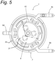
- Fig. 1 shows an egg carrier 1 according to the invention in perspective view.
- the egg carrier will be described to figures 1-5 .
- the egg carrier 1 is configured for holding an individual egg (not shown). Also, the egg carrier is configured to be used in an egg handling system, like an egg conveying system 2 as shown in fig. 6-9 .
- the egg carrier 1 comprises an egg accommodation 3.
- the egg accommodation 3 is delimited by an opening 10 and a bowl shaped portion 11.
- the opening 10 is arranged opposite the bowl shaped portion 11.
- the opening 10 has a generally circular shape for introducing an egg into the egg accommodation 3.
- the bowl shaped portion 11 has a cavity 27 to receive a portion of an egg.
- the cavity 27 has a surface that contacts the egg, which surface has a texture designed to slide the tip of the egg to the deepest point of the cavity 27.
- the cavity 27 has a radius r that is greater than the radius of a pointed half of an egg.
- the cavity 27 has a radius r of about 16 mm.
- the egg carrier 1 comprising two housing members 7, 8, The two housing members 7, 8 extend around a central axis 9 of the egg carrier 1.
- the two housing members 7, 8 extend around the egg accommodation 1.
- the two housing members 7, 8 extend continuously around the egg accommodation 1.
- the outer housing member 7 has a generally cylindrical shape.
- the inner housing member 8 extends mainly within the outer housing member 7 as can be best seen in fig. 5 .
- the bowl shaped portion 11 that has a cavity 27 to receive a portion of an egg is part of the inner housing member 8.
- the inner housing member 8 is restraint within the outer housing member 8 by a closing plate member 28 as is clear from fig. 4 , and fig. 5 where the closing plate member 28 is taken away.
- the two housing members 7, 8 are mutually movable coupled.
- the two coupled housing members 7, 8 are mutually moveable around the central axis.
- the egg carrier 1 comprises an egg clamping system 4.
- the egg clamping system 4 is configured to secure an egg in the egg accommodation 3. In order to secure an egg in, and to introduce and release an egg in and out the egg accommodation 3, the egg clamping system 4 is moveable between an egg securing position and an egg release position which is shown in fig. 2 .
- the egg clamping system 4 comprises a number of egg clamping members 14.
- the egg clamping member 14 can be flexible, deformable when required to conform the egg clamping member 14 to the shape of an egg.
- the egg clamping system 4 has three egg clamping members 14.
- the each of the three egg clamping members 14 are moveable between the egg securing position and the egg release position.
- the three egg clamping members 14 are arranged symmetrically around the central axis 9 of the egg carrier 1.
- the three egg clamping members 14 are moveable in a pure radial direction towards and from the central axis 9 in order to move between the egg securing position and the egg release position.
- the egg carrier 1 comprises an operating system 5.
- the operating system 5 is coupled with the egg clamping system 4 to move the egg clamping system 4 between the egg securing position and the egg release position.
- the operating system 5 is configured to operate the clamping system 4, or in other words, the clamping system 4 is set in motion through the operating system 5.
- the operating system 5 comprises, in this case four, operating members 6a, 6b, 6c, 6d. All of these four operating members 6a, 6b, 6c, 6d are operable externally from the egg carrier 1.
- the operating system 5 is distributed over both the two moveably coupled housing members 7, 8. This means that each of the two moveably coupled housing members 7, 8 are provided with at least one of the operating members 6a, 6b, 6c, 6d.
- the number of cooperating operating members 6a, 6b, 6c, 6d comprises a pair of spaced operating members. Like for example such a pair is operating member 6a and 6b.
- the operating member 6a and 6b are arranged at opposite sides of the egg carrier 1.
- the operating member 6a and 6b are arranged at a side of the egg carrier 1 opposite the egg accommodation 3.
- the operating member 6a is firmly connect to the outer housing member 7.
- the operating member 6b is firmly connect to the inner housing member 8.
- a torque can be applied to the egg carrier 1 through the pair of operating members 6a and 6b.
- the two moveably coupled outer- and inner- housing members will start rotating with respect to each other around the central axis 9 when a torque is applied through the pair of operating members 6a and 6b.
- the operating member 6b and 6d are arranged at opposite sides of the egg carrier 1.
- the operating member 6b and 6d are arranged at a side of the egg carrier 1 opposite the egg accommodation 3.
- the operating member 6b and 6d are firmly connected to the egg carrier 1, here to the inner housing member 8.
- a torque can be applied to the egg carrier 1 through the pair of operating members 6b and 6d.
- the entire egg carrier 1 will start to rotate with respect to the horizontal when a torque is applied through the pair of operating members 6b and 6d.
- the operating member 6c is useful.
- Operating members 6b and 6c have hooks 23.
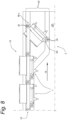
- operating members 6b and 6d also has a hook 24. These hooks 23, 24 can receive a pin 30, shown in fig. 8 , that defines the rotation of the egg carrier 1. In this case, all of the operating members 6b, 6c and 6d are integrally formed with the inner housing member 8.
- the inner housing member 8 has a central body 31 and a continuous annular ring member 32 around the central body.
- the central body 31 forms the cavity 27.
- the egg clamping members 14 and the operating members 6b, 6c and 6d protrude from the annular ring member 32.
- a respective egg clamping member 14 and a respective operating member 6b, 6c and 6d protrude from the annular ring member 32 from about the same position on the annular ring member 32. Therefore a direct coupling between an egg and an outside support, like a conveyer 2 or a tray as shown in fig. 13 , is obtained. This provides a well manageable support of an egg in terms of positional accuracy.
- the operating member 6d and the respective clamping member 14 are vertically aligned in order to provide optimal support to an egg in the egg accommodation 3 in case of a vertical load on the egg.
- the outer housing member 7 comprises an operating member 6a.
- the operating member 6a has a cam 26.
- the cam 26 is firmly connected with the outer housing member 7.
- the operating member 6a is integrally formed with the closing plate member 28.
- the closing plate member 28 forms a unity with the outer housing member 7.
- the cam 26 is arranged at an outer circumference of the outer housing member 7.
- the cam 26 is arranged at a side of the egg carrier 1 opposite the egg accommodation 3.
- the inner housing member 8 comprises an operating member 6b.
- the operating member 6b has a cam 25.
- the cam 25 is firmly connected with the inner housing member b.
- the cam 25 is arranged at an outer circumference of the inner housing member 8.
- the cam 25 is arranged at a side of the egg carrier 1 opposite the egg accommodation 3.
- the pair of cams 25, 26 can be controlled by a cam profile. In other words, the pair of cams 25, 26 do in use form a part of a cam mechanism.
- the operating system 5 comprises a pair of cooperating transmission members 12, 13. Each transmission member 12, 13 is coupled with one of the at least two housing members 7, 8.
- the transmission member 12 is coupled with the inner housing member and is integrally formed with a clamping member 14.
- the transmission member 13 is part of the outer housing member 7.
- the transmission member 13 is integrally formed with the outer housing member 7.
- the pair of cooperating transmission members 12, 13 have bodies that taper in opposite directions along the circumference. Therefore, when the pair of cooperating transmission members 12, 13 mutually engage, they move the egg clamping member 14 radially inward towards the central axis 9 under the effect of wedging when the two housing members 7, 8 mutually rotate.
- the clamping member 14 can move back when allowed under spring action. Therefore, the clamping member 14 is supported by a leaf spring 29. In this case, each respective clamping member 14 is driven through a respective pair of cooperating transmission members 12, 13. Therefore, the operating system 5 that includes the cooperating transmission members 12, 13, is configured to move all of the number of egg clamping members 14 in an even manner
- the egg carrier 1 comprises a prestress system 15.
- the prestress system 15 is configured to prestress the egg clamping system 4 towards the egg securing position, which is the default position when the egg carrier is in the idle state.
- the prestress system 15 engages the two housing members 7, 8 to force them in a predetermined mutual angular position.
- the operating system 5 works opposite the prestress system 15 to force the egg clamping system 4 towards the egg release position.
- the prestress system 15 is in the form of a torsion spring.
- the coil of the torsion spring is centrally arranged in the egg carrier 1.
- the coil of the torsion spring extends centrally along the central axis 9.
- the torsion spring has a spring stiffness between 0,4 and 1 Nmm / °. This way, there is a balance between positional accuracy of the egg in the egg carrier 1 and the gentle care that is required while handling an egg.
- the prestress system 15 may comprises a number of torsion springs, like three torsion springs. In use, the prestress system 15 exerts an effective torque on the egg carrier 1 of between 100 to 300 Nmm.
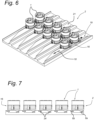
- Fig. 6 shows a portion of an egg conveyer 2 in perspective view.
- Fig. 7 shows a side view of the egg conveyer 2 of fig. 6 .
- the egg conveyer 2 forms a part of an egg processing system which system is not described.
- the egg conveyor 2 moves an egg carrier 1 in a conveying direction 18.
- the egg conveyer 2 comprises a first cam profile 19 for contacting the pair of spaced operating members 6a, 6b.
- the conveyer 2 comprises a substantially flat conveying surface 21.
- the first cam profile 19 is arranged in the substantially flat conveying surface 21.
- the operating members 6a, 6b are arranged at a side of the egg carrier 1 opposite the egg accommodation 3.
- the cam profile 19 contacts the operating members 6a, 6b in order to operate the egg clamping system 4 between the egg securing position and the egg release position.
- the cam profile 19 contacts the operating members 6a, 6b through the cams 25, 26.
- the cam profile 19 contacts the operating members 6a, 6b through the cams 25, 26 via wheel members 34.
- Fig. 8 shows a side view of a different portion of the egg conveyer 2.
- the conveyer comprises a second cam profile 20.
- the second cam profile 20 is configured for contacting the pair of operating members 6b, 6c, 6d.
- the operating members 6b, 6c, 6d are arranged at opposite sides of the egg carrier 1 in order to tilt the egg carrier 1 around a horizontal axis.
- the second cam profile 20 is arranged in a plane 22 transverse with respect to the flat conveying surface 21.
- FIGS. 6-9 show assemblies 16 of a number of interlinked egg carriers 1 of fig. 1-5 .
- the egg carriers 1 are interlinked through the operating members 6b, 6c and 6d, in particular through the hooks 23, 24 thereof.
- Fig. 9 shows tray 17.
- the tray comprises a tray interior 33 accommodating an assembly 16 of interlinked egg carriers 1.
- the respective operating systems 5 are coupled (not shown) for joint operation of interlinked egg carriers 1. It is of course conceivable that egg carriers 1 are individually operated in the tray 17.
- the trays 17 are moved in a conveyer 2 which is a slide in this case.
- any other suitable conveyer will suffice, like e.g. a conveyer belt.
- the egg carrier 1 can be used by an egg conveyer 2 in an egg processing system comprising one or more of the following steps;
- the egg processing system comprises the step of tilting the egg carrier 1 around a horizontal axis to face the opening 10 of the egg accommodation 3 downwards, and releasing an egg clamping system 4 to remove the egg out of the egg accommodation 3.
- the settling time is at least 5 minutes, in particular between 5 and 15 minutes, like for example 10 minutes.
- the longitudinal axis of the egg in the egg accommodation 3 makes an angle of about 45° with the vertical.
- a plurality of eggs can be processed or operated simultaneously of individually as desired. This can also differ per process step. For example transport of egg carriers 1 can be simultaneously while the taking of an allantoic fluid sample from the egg is performed individually or in other words subsequent.
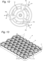
- FIGS 10 - 12 show a second embodiment of an egg carrier according to the invention in different views. In general only differences with the first embodiment of figures 1-5 are described.
- the operating members 60b, 60c and 60d are firmly connected to the inner housing member 8 of the egg carrier 1.
- the operating members 60b, 60c and 60d are each configured to slide in a respective socket.
- the operating members 60b, 60c and 60d have rounded ends 35.
- the operating members 60b, 60c and 60d are provided with a through hole 36.
- the operating member 60a is firmly connected to the outer housing member 7 of the egg carrier 1.
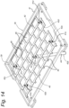
- Fig. 13 shows a tray 17 in perspective view, supporting an assembly 16 of egg carriers 1 of fig. 10 .
- the egg carriers 1 are assembled together through the tray 17 to form the assembly 16.
- the egg carriers 1 are assembled in the interior 33 of the tray 17. Therefore, the tray 17 comprises a plurality of sockets 37.
- the sockets 37 are configured to receive the operating members 60b, 60c and 60d in a sliding manner.
- the tray 17 secures the inner housing member 8 of the egg carrier 1 while the outer housing member 7 of the egg carrier 1 is free to rotate with respect to the inner housing member 8.
- the tray 17 has an open structure to enable access to the operating members 60a that is firmly connected to the outer housing member 7 of the egg carrier 1.
- the tray 17 thus comprises a tray interior 33 accommodating an assembly 16, wherein operating members are connectable for joint operation of interlinked egg carriers 1.
- Fig. 14 shows in perspective view an operating station 38 for the tray of fig. 13 .
- the operation station 38 has a receiving space 39 for receiving a tray 17 therein in a tray installed position (not shown). In the tray installed position the bottom of the tray 17 faces the operation station 38.
- the operating station 38 comprises an operating member 40. In this case, the operating member 40 is out of sheet material.
- the operating member 40 comprises a plurality of stops 45.
- the plurality of stops 45 matches the plurality of egg carriers 1 of tray 17 to facilitate simultaneous operating of all of the plurality of egg carriers 1 of tray 17 through the operating member 40 of the operating station 38.
- the stops 45 are configured to each contact and operate an associated operating member 60a of the egg carrier 1.
- a stop 45 can have any suitable configuration, like e.g.
- the parallelogram linkage system has a number of hinges 41A-41E and a number of link members 42A-42E.
- One link member 42A comprises a lever 44.
- the lever 44 is aligned with the link member 42A.
- the lever 44 is operable from the exterior of the operating station 38.
- the parallelogram linkage system is configured such that the movement of the operating member 40 corresponds with a required movement of an operating member 60a to operate the associated egg carrier 1 between the egg securing position and the egg release position.
Landscapes
- Life Sciences & Earth Sciences (AREA)
- Environmental Sciences (AREA)
- Animal Husbandry (AREA)
- Biodiversity & Conservation Biology (AREA)
- Health & Medical Sciences (AREA)
- Immunology (AREA)
- Mechanical Engineering (AREA)
- Physics & Mathematics (AREA)
- Pathology (AREA)
- Chemical & Material Sciences (AREA)
- Analytical Chemistry (AREA)
- Biochemistry (AREA)
- General Health & Medical Sciences (AREA)
- General Physics & Mathematics (AREA)
- Engineering & Computer Science (AREA)
- Birds (AREA)
- Meat, Egg Or Seafood Products (AREA)
- Wrapping Of Specific Fragile Articles (AREA)
Claims (15)
- Eiträger (1) zum Halten eines Eis in einem Eihandhabungssystem (2), wobei der Eiträger (1) Folgendes aufweist;- eine Eiaufnahme (3),- ein Eiklemmsystem (4) zum Sichern eines Eis in der Eiaufnahme (3), wobei das Eiklemmsystem (4) zwischen einer Eisicherungsposition und einer Eifreigabeposition bewegbar ist,- ein Betätigungssystem (5), das mit dem Eiklemmsystem (4) gekoppelt ist, um das Eiklemmsystem (4) zwischen der Eisicherungsposition und der Eifreigabeposition zu bewegen.
wobei das Betätigungssystem (5) ein Betätigungsbauteil (6a, 6b, 6c, 6d) aufweist, das von dem Eiträger (1) extern betätigbar ist,- gekennzeichnet durchmindestens zwei gegenseitig bewegbare gekoppelte Gehäusebauteile (7, 8), die sich um eine Mittelachse (9) des Eiträgers (1) und der Eiaufnahme (3) erstrecken, wobei das Betätigungssystem (5) eine Anzahl von zusammenwirkenden Übertragungsbauteilen (12, 13) aufweist, wobei jedes Übertragungsbauteil (12, 13) mit einem der mindestens zwei Gehäusebauteile (7, 8) gekoppelt ist. - Eiträger nach Anspruch 1, wobei das Betätigungssystem über beide der zwei bewegbar gekoppelten Gehäusebauteile verteilt ist.
- Eiträger nach einem der vorhergehenden Ansprüche, wobei die mindestens zwei gekoppelten Gehäusebauteile gegenseitig um die Mittelachse drehbar sind.
- Eiträger nach einem der vorangehenden Ansprüche, mit einer Öffnung (10) zum Einführen eines Eis in die Eiaufnahme (3), und wobei eines der Gehäusebauteile einen schüsselförmigen Abschnitt (11) gegenüber der Öffnung aufweist.
- Eiträger nach einem der vorangehenden Ansprüche, wobei mindestens zwei der Anzahl von zusammenwirkenden Übertragungsbauteilen gegenseitig eingreifen, um das Eiklemmbauteil (14) unter der Wirkung eines Verkeilens zu bewegen.
- Eiträger nach einem der vorangehenden Ansprüche, wobei mindestens eines der Anzahl von zusammenwirkenden Übertragungsbauteilen einstückig mit einem der mindestens zwei Gehäusebauteile ausgebildet ist, und/oder wobei die Anzahl von zusammenwirkenden Betätigungsbauteilen ein Paar von beabstandeten Betätigungsbauteilen aufweist, und/oder wobei die Anzahl von zusammenwirkenden Betätigungsbauteilen ein Paar von Betätigungsbauteilen aufweist, die an einer Seite des Eiträgers gegenüber der Eiaufnahme (3) angeordnet sind, und/oder wobei mindestens eines der Anzahl von zusammenwirkenden Betätigungsbauteilen einstückig mit einem der mindestens zwei Gehäusebauteile ausgebildet ist.
- Eiträger nach einem der vorangehenden Ansprüche, wobei das Eiklemmsystem eine Anzahl von Eiklemmbauteilen (14) aufweist, insbesondere drei Eiklemmbauteile, und wobei jedes der Anzahl von Eiklemmbauteilen zwischen der Eisicherungsposition und der Eifreigabeposition bewegbar ist.
- Eiträger nach Anspruch 7, wobei die Anzahl von Eiklemmbauteilen symmetrisch um die Mittelachse herum angeordnet ist, und/oder wobei das Betätigungssystem konfiguriert ist, um alle der Anzahl von Eiklemmbauteilen in einer gleichmäßigen Weise zu bewegen.
- Eiträger nach einem der vorangehenden Ansprüche, mit einem Vorspannsystem (15) zum Vorspannen des Eiklemmsystems in Richtung der Eisicherungsposition.
- Anordnung (16) einer Anzahl, insbesondere zwischen 35 bis 45, von miteinander verbundenen Eiträgern (1) nach einem der vorangehenden Ansprüche, wobei vorzugsweise die Eiträger (1) durch mindestens eines der extern betätigbaren Betätigungsbauteile (6a, 6b, 6c, 6d) miteinander verbunden sind.
- Ablage (17) mit einem Ablageinnenraum (33), der eine Anordnung (16) nach Anspruch 10 aufnimmt, wobei Betätigungsbauteile zur gemeinsamen Betätigung von miteinander verbundenen Eiträgern (1) gekoppelt oder verbindbar sind.
- Eiverarbeitungssystem mit einem Eihalter, wie einer Ablage (17) nach Anspruch 11, oder einem Eiförderer (2), und einem Eiträger (1) nach einem der vorangehenden Ansprüche 1-9 zum Fördern des Eiträgers (1) in einer Förderrichtung (18), wobei der Eiförderer (2) ein erstes Nockenprofil (19) zum Kontaktieren eines Paares von beabstandeten Betätigungsbauteilen (6a, 6b, 6c, 6d) aufweist, um das Eiklemmsystem zwischen der Eisicherungsposition und der Eifreigabeposition zu betätigen, und wobei der Eiförderer (2) vorzugsweise ein zweites Nockenprofil (20) zum Kontaktieren des Paares von beabstandeten Betätigungsbauteilen (6a, 6b, 6c, 6d) aufweist, die an gegenüberliegenden Seiten des Eiträgers (1) angeordnet sind, um den Eiträger (1) um eine horizontale Achse zu neigen, und/oder wobei der Eiförderer (2) eine im Wesentlichen ebene Förderfläche (21) aufweist und das erste Nockenprofil (19) in der im Wesentlichen ebenen Förderfläche (21) angeordnet ist und/oder wobei das zweite Nockenprofil in einer Ebene (22) quer mit Bezug auf die ebene Förderfläche (21) angeordnet ist.
- Verwendung eines Eiverarbeitungssystems nach Anspruch 12, mit den folgenden Schritten;- Aufnehmen eines Eis in einem Aufnahmeraum (3),- Positionieren des Eis in einer vorbestimmten Probenahmeposition mit Bezug auf den Eiträger (1),- Sichern des Eis in dem Aufnahmeraum (3) in der vorbestimmten Probenahmeposition mit Bezug auf den Eiträger (1),- Kippen des Eiträgers (1) um eine horizontale Achse in eine gekippte Position,- Halten des Eis in der vorbestimmten Kippung während einer Setzzeit, vor einem- Entnehmen einer Allantoisflüssigkeitsprobe aus dem Ei.
- Verwendung nach Anspruch 13, wobei die Setzzeit mindestens 30 Sekunden beträgt, insbesondere zwischen 2 und 15 Minuten, wie zum Beispiel 10 Minuten, und/oder wobei in der gekippten Position die Längsachse des Eis einen Winkel mit der Vertikalen zwischen 20° und 90° bildet, wie zum Beispiel etwa 45°.
- Verwendung nach einem der vorangehenden Ansprüche 13-14, mit einem gleichzeitigen Betätigen einer Vielzahl von Eiträgern und/oder Kippen des Eiträgers um eine horizontale Achse, um einer Öffnung der Eiaufnahme nach unten zugewandt zu sein, und insbesondere Freigeben eines Eiklemmsystems, um das Ei aus der Aufnahme zu entfernen.
Priority Applications (1)
| Application Number | Priority Date | Filing Date | Title |
|---|---|---|---|
| PL17811452.6T PL3709795T3 (pl) | 2017-11-14 | 2017-11-14 | Podstawka jaja oraz urządzenie do obchodzenia się z jajami |
Applications Claiming Priority (1)
| Application Number | Priority Date | Filing Date | Title |
|---|---|---|---|
| PCT/EP2017/079199 WO2019096372A1 (en) | 2017-11-14 | 2017-11-14 | Egg support and apparatus for handling eggs |
Publications (2)
| Publication Number | Publication Date |
|---|---|
| EP3709795A1 EP3709795A1 (de) | 2020-09-23 |
| EP3709795B1 true EP3709795B1 (de) | 2024-06-12 |
Family
ID=60629635
Family Applications (1)
| Application Number | Title | Priority Date | Filing Date |
|---|---|---|---|
| EP17811452.6A Active EP3709795B1 (de) | 2017-11-14 | 2017-11-14 | Eierträger und vorrichtung zur handhabung von eiern |
Country Status (8)
| Country | Link |
|---|---|
| US (1) | US11864534B2 (de) |
| EP (1) | EP3709795B1 (de) |
| AU (1) | AU2017440064B2 (de) |
| CA (1) | CA3082373A1 (de) |
| ES (1) | ES2986901T3 (de) |
| PL (1) | PL3709795T3 (de) |
| PT (1) | PT3709795T (de) |
| WO (1) | WO2019096372A1 (de) |
Families Citing this family (4)
| Publication number | Priority date | Publication date | Assignee | Title |
|---|---|---|---|---|
| NL2024699B1 (en) | 2020-01-17 | 2021-10-13 | In Ovo Holding B V | Egg Characteristic Determining Device |
| NL2026004B1 (en) | 2020-07-05 | 2022-03-11 | In Ovo Holding B V | Egg Determining Method and Device |
| US20240010446A1 (en) * | 2020-12-03 | 2024-01-11 | Nectra | Individual egg transport device, complementary filling facility and associated method |
| FR3116992A1 (fr) * | 2020-12-03 | 2022-06-10 | Nectra | Dispositif individuel de transport d’œuf, installation et procédé utilisant un tel dispositif |
Family Cites Families (4)
| Publication number | Priority date | Publication date | Assignee | Title |
|---|---|---|---|---|
| US4360099A (en) * | 1980-10-24 | 1982-11-23 | Otto Niederer Sons, Inc. | Egg transfer apparatus |
| US4487321A (en) * | 1982-07-01 | 1984-12-11 | Diamond Automations, Inc. | Article coding and separating system |
| US6029424A (en) * | 1998-01-16 | 2000-02-29 | Diamond Automations, Inc. | High-speed egg processing system and method |
| MX2010000454A (es) * | 2007-07-10 | 2010-04-22 | Sanofi Pasteur Inc | Aparato y metodo para recolectar productos biologicos de huevos. |
-
2017
- 2017-11-14 EP EP17811452.6A patent/EP3709795B1/de active Active
- 2017-11-14 AU AU2017440064A patent/AU2017440064B2/en active Active
- 2017-11-14 PL PL17811452.6T patent/PL3709795T3/pl unknown
- 2017-11-14 PT PT178114526T patent/PT3709795T/pt unknown
- 2017-11-14 WO PCT/EP2017/079199 patent/WO2019096372A1/en not_active Ceased
- 2017-11-14 ES ES17811452T patent/ES2986901T3/es active Active
- 2017-11-14 CA CA3082373A patent/CA3082373A1/en active Pending
- 2017-11-14 US US16/763,239 patent/US11864534B2/en active Active
Also Published As
| Publication number | Publication date |
|---|---|
| EP3709795A1 (de) | 2020-09-23 |
| WO2019096372A1 (en) | 2019-05-23 |
| AU2017440064B2 (en) | 2024-03-21 |
| ES2986901T3 (es) | 2024-11-13 |
| CA3082373A1 (en) | 2019-05-23 |
| PT3709795T (pt) | 2024-06-25 |
| US20210169051A1 (en) | 2021-06-10 |
| PL3709795T3 (pl) | 2024-10-28 |
| AU2017440064A1 (en) | 2020-05-28 |
| US11864534B2 (en) | 2024-01-09 |
Similar Documents
| Publication | Publication Date | Title |
|---|---|---|
| EP3709795B1 (de) | Eierträger und vorrichtung zur handhabung von eiern | |
| US8424940B2 (en) | Resilient clamp for holding a container by the neck | |
| JP6506304B2 (ja) | 実験室自動化システムにおける生物学的製剤のコンテナ運搬用改良装置 | |
| EP1038443B1 (de) | Aufhängehaken für Geflügel | |
| JP2002505653A (ja) | 容器を処理室内へ搬入しないしは処理室内から搬出する装置 | |
| US9862087B2 (en) | Device for blocking eyeglass lenses | |
| CN111703850B (zh) | 蛋加工系统和侵入式蛋加工装置 | |
| EP1790593A1 (de) | Ringförderer zum Übergeben von Waren, insbesondere von Lebensmitteln | |
| EP1118426A2 (de) | Bearbeitungsanlage mit Einrichtung zur Halterung und Zentrierung von Karosserien in Bearbeitungsstationen | |
| EP0256991A2 (de) | Vorrichtung zum Transfer und gleichzeitigen Umwenden von Gegenständen | |
| US4134333A (en) | Method and means for transferring rows of articles | |
| KR20180108045A (ko) | 핸들러 | |
| CN113697471B (zh) | 用于预设夹具臂位置的设备和容器运输设备 | |
| US8684168B2 (en) | Handler for electronic components, in particular IC'S, comprising a pneumatic cylinder displacement unit for moving plungers | |
| EP3421134B1 (de) | Zentrifugale verarbeitungseinheit | |
| CS233747B2 (en) | Feeding device | |
| US20240425287A1 (en) | Conveyor system for selectively diverting objects | |
| EP3421135A1 (de) | Zentrifugale verarbeitungseinheit | |
| KR20210156623A (ko) | 피가공물의 충격 완화와 정렬을 위한 낙하 안내 장치 | |
| US20170349388A1 (en) | A transportation system | |
| JPH01209213A (ja) | コンベアのパレット循環装置 | |
| US20240359848A1 (en) | System, method, and apparatus for capsule fabrication | |
| EP1304919A1 (de) | Verfahren und vorrichtung zur bearbeitung von schlachtgeflügel | |
| JP6805474B2 (ja) | 容器滅菌装置の移送群装置 | |
| SU1175821A1 (ru) | Устройство дл перегрузки цилиндрических грузов |
Legal Events
| Date | Code | Title | Description |
|---|---|---|---|
| STAA | Information on the status of an ep patent application or granted ep patent |
Free format text: STATUS: UNKNOWN |
|
| STAA | Information on the status of an ep patent application or granted ep patent |
Free format text: STATUS: THE INTERNATIONAL PUBLICATION HAS BEEN MADE |
|
| PUAI | Public reference made under article 153(3) epc to a published international application that has entered the european phase |
Free format text: ORIGINAL CODE: 0009012 |
|
| STAA | Information on the status of an ep patent application or granted ep patent |
Free format text: STATUS: REQUEST FOR EXAMINATION WAS MADE |
|
| 17P | Request for examination filed |
Effective date: 20200514 |
|
| AK | Designated contracting states |
Kind code of ref document: A1 Designated state(s): AL AT BE BG CH CY CZ DE DK EE ES FI FR GB GR HR HU IE IS IT LI LT LU LV MC MK MT NL NO PL PT RO RS SE SI SK SM TR |
|
| AX | Request for extension of the european patent |
Extension state: BA ME |
|
| DAV | Request for validation of the european patent (deleted) | ||
| DAX | Request for extension of the european patent (deleted) | ||
| GRAP | Despatch of communication of intention to grant a patent |
Free format text: ORIGINAL CODE: EPIDOSNIGR1 |
|
| STAA | Information on the status of an ep patent application or granted ep patent |
Free format text: STATUS: GRANT OF PATENT IS INTENDED |
|
| INTG | Intention to grant announced |
Effective date: 20240110 |
|
| GRAS | Grant fee paid |
Free format text: ORIGINAL CODE: EPIDOSNIGR3 |
|
| GRAA | (expected) grant |
Free format text: ORIGINAL CODE: 0009210 |
|
| STAA | Information on the status of an ep patent application or granted ep patent |
Free format text: STATUS: THE PATENT HAS BEEN GRANTED |
|
| AK | Designated contracting states |
Kind code of ref document: B1 Designated state(s): AL AT BE BG CH CY CZ DE DK EE ES FI FR GB GR HR HU IE IS IT LI LT LU LV MC MK MT NL NO PL PT RO RS SE SI SK SM TR |
|
| REG | Reference to a national code |
Ref country code: GB Ref legal event code: FG4D |
|
| REG | Reference to a national code |
Ref country code: CH Ref legal event code: EP |
|
| REG | Reference to a national code |
Ref country code: PT Ref legal event code: SC4A Ref document number: 3709795 Country of ref document: PT Date of ref document: 20240625 Kind code of ref document: T Free format text: AVAILABILITY OF NATIONAL TRANSLATION Effective date: 20240617 |
|
| REG | Reference to a national code |
Ref country code: IE Ref legal event code: FG4D |
|
| REG | Reference to a national code |
Ref country code: DE Ref legal event code: R096 Ref document number: 602017082558 Country of ref document: DE |
|
| REG | Reference to a national code |
Ref country code: NL Ref legal event code: FP |
|
| PG25 | Lapsed in a contracting state [announced via postgrant information from national office to epo] |
Ref country code: BG Free format text: LAPSE BECAUSE OF FAILURE TO SUBMIT A TRANSLATION OF THE DESCRIPTION OR TO PAY THE FEE WITHIN THE PRESCRIBED TIME-LIMIT Effective date: 20240612 |
|
| PG25 | Lapsed in a contracting state [announced via postgrant information from national office to epo] |
Ref country code: HR Free format text: LAPSE BECAUSE OF FAILURE TO SUBMIT A TRANSLATION OF THE DESCRIPTION OR TO PAY THE FEE WITHIN THE PRESCRIBED TIME-LIMIT Effective date: 20240612 Ref country code: FI Free format text: LAPSE BECAUSE OF FAILURE TO SUBMIT A TRANSLATION OF THE DESCRIPTION OR TO PAY THE FEE WITHIN THE PRESCRIBED TIME-LIMIT Effective date: 20240612 |
|
| REG | Reference to a national code |
Ref country code: LT Ref legal event code: MG9D |
|
| PG25 | Lapsed in a contracting state [announced via postgrant information from national office to epo] |
Ref country code: GR Free format text: LAPSE BECAUSE OF FAILURE TO SUBMIT A TRANSLATION OF THE DESCRIPTION OR TO PAY THE FEE WITHIN THE PRESCRIBED TIME-LIMIT Effective date: 20240913 |
|
| PG25 | Lapsed in a contracting state [announced via postgrant information from national office to epo] |
Ref country code: LV Free format text: LAPSE BECAUSE OF FAILURE TO SUBMIT A TRANSLATION OF THE DESCRIPTION OR TO PAY THE FEE WITHIN THE PRESCRIBED TIME-LIMIT Effective date: 20240612 |
|
| PG25 | Lapsed in a contracting state [announced via postgrant information from national office to epo] |
Ref country code: NO Free format text: LAPSE BECAUSE OF FAILURE TO SUBMIT A TRANSLATION OF THE DESCRIPTION OR TO PAY THE FEE WITHIN THE PRESCRIBED TIME-LIMIT Effective date: 20240912 Ref country code: LV Free format text: LAPSE BECAUSE OF FAILURE TO SUBMIT A TRANSLATION OF THE DESCRIPTION OR TO PAY THE FEE WITHIN THE PRESCRIBED TIME-LIMIT Effective date: 20240612 Ref country code: HR Free format text: LAPSE BECAUSE OF FAILURE TO SUBMIT A TRANSLATION OF THE DESCRIPTION OR TO PAY THE FEE WITHIN THE PRESCRIBED TIME-LIMIT Effective date: 20240612 Ref country code: GR Free format text: LAPSE BECAUSE OF FAILURE TO SUBMIT A TRANSLATION OF THE DESCRIPTION OR TO PAY THE FEE WITHIN THE PRESCRIBED TIME-LIMIT Effective date: 20240913 Ref country code: FI Free format text: LAPSE BECAUSE OF FAILURE TO SUBMIT A TRANSLATION OF THE DESCRIPTION OR TO PAY THE FEE WITHIN THE PRESCRIBED TIME-LIMIT Effective date: 20240612 Ref country code: BG Free format text: LAPSE BECAUSE OF FAILURE TO SUBMIT A TRANSLATION OF THE DESCRIPTION OR TO PAY THE FEE WITHIN THE PRESCRIBED TIME-LIMIT Effective date: 20240612 Ref country code: RS Free format text: LAPSE BECAUSE OF FAILURE TO SUBMIT A TRANSLATION OF THE DESCRIPTION OR TO PAY THE FEE WITHIN THE PRESCRIBED TIME-LIMIT Effective date: 20240912 |
|
| REG | Reference to a national code |
Ref country code: ES Ref legal event code: FG2A Ref document number: 2986901 Country of ref document: ES Kind code of ref document: T3 Effective date: 20241113 |
|
| REG | Reference to a national code |
Ref country code: AT Ref legal event code: MK05 Ref document number: 1693402 Country of ref document: AT Kind code of ref document: T Effective date: 20240612 |
|
| PGFP | Annual fee paid to national office [announced via postgrant information from national office to epo] |
Ref country code: PT Payment date: 20241025 Year of fee payment: 8 |
|
| PGFP | Annual fee paid to national office [announced via postgrant information from national office to epo] |
Ref country code: NL Payment date: 20241111 Year of fee payment: 8 |
|
| PGFP | Annual fee paid to national office [announced via postgrant information from national office to epo] |
Ref country code: DE Payment date: 20241128 Year of fee payment: 8 |
|
| PGFP | Annual fee paid to national office [announced via postgrant information from national office to epo] |
Ref country code: BE Payment date: 20241126 Year of fee payment: 8 Ref country code: PL Payment date: 20241112 Year of fee payment: 8 |
|
| PGFP | Annual fee paid to national office [announced via postgrant information from national office to epo] |
Ref country code: FR Payment date: 20241126 Year of fee payment: 8 |
|
| PG25 | Lapsed in a contracting state [announced via postgrant information from national office to epo] |
Ref country code: EE Free format text: LAPSE BECAUSE OF FAILURE TO SUBMIT A TRANSLATION OF THE DESCRIPTION OR TO PAY THE FEE WITHIN THE PRESCRIBED TIME-LIMIT Effective date: 20240612 |
|
| PG25 | Lapsed in a contracting state [announced via postgrant information from national office to epo] |
Ref country code: IS Free format text: LAPSE BECAUSE OF FAILURE TO SUBMIT A TRANSLATION OF THE DESCRIPTION OR TO PAY THE FEE WITHIN THE PRESCRIBED TIME-LIMIT Effective date: 20241012 Ref country code: AT Free format text: LAPSE BECAUSE OF FAILURE TO SUBMIT A TRANSLATION OF THE DESCRIPTION OR TO PAY THE FEE WITHIN THE PRESCRIBED TIME-LIMIT Effective date: 20240612 |
|
| PG25 | Lapsed in a contracting state [announced via postgrant information from national office to epo] |
Ref country code: CZ Free format text: LAPSE BECAUSE OF FAILURE TO SUBMIT A TRANSLATION OF THE DESCRIPTION OR TO PAY THE FEE WITHIN THE PRESCRIBED TIME-LIMIT Effective date: 20240612 |
|
| PG25 | Lapsed in a contracting state [announced via postgrant information from national office to epo] |
Ref country code: SK Free format text: LAPSE BECAUSE OF FAILURE TO SUBMIT A TRANSLATION OF THE DESCRIPTION OR TO PAY THE FEE WITHIN THE PRESCRIBED TIME-LIMIT Effective date: 20240612 Ref country code: RO Free format text: LAPSE BECAUSE OF FAILURE TO SUBMIT A TRANSLATION OF THE DESCRIPTION OR TO PAY THE FEE WITHIN THE PRESCRIBED TIME-LIMIT Effective date: 20240612 |
|
| PG25 | Lapsed in a contracting state [announced via postgrant information from national office to epo] |
Ref country code: SM Free format text: LAPSE BECAUSE OF FAILURE TO SUBMIT A TRANSLATION OF THE DESCRIPTION OR TO PAY THE FEE WITHIN THE PRESCRIBED TIME-LIMIT Effective date: 20240612 |
|
| PGFP | Annual fee paid to national office [announced via postgrant information from national office to epo] |
Ref country code: IT Payment date: 20241125 Year of fee payment: 8 Ref country code: ES Payment date: 20241218 Year of fee payment: 8 |
|
| PG25 | Lapsed in a contracting state [announced via postgrant information from national office to epo] |
Ref country code: SM Free format text: LAPSE BECAUSE OF FAILURE TO SUBMIT A TRANSLATION OF THE DESCRIPTION OR TO PAY THE FEE WITHIN THE PRESCRIBED TIME-LIMIT Effective date: 20240612 Ref country code: SK Free format text: LAPSE BECAUSE OF FAILURE TO SUBMIT A TRANSLATION OF THE DESCRIPTION OR TO PAY THE FEE WITHIN THE PRESCRIBED TIME-LIMIT Effective date: 20240612 Ref country code: RO Free format text: LAPSE BECAUSE OF FAILURE TO SUBMIT A TRANSLATION OF THE DESCRIPTION OR TO PAY THE FEE WITHIN THE PRESCRIBED TIME-LIMIT Effective date: 20240612 Ref country code: IS Free format text: LAPSE BECAUSE OF FAILURE TO SUBMIT A TRANSLATION OF THE DESCRIPTION OR TO PAY THE FEE WITHIN THE PRESCRIBED TIME-LIMIT Effective date: 20241012 Ref country code: EE Free format text: LAPSE BECAUSE OF FAILURE TO SUBMIT A TRANSLATION OF THE DESCRIPTION OR TO PAY THE FEE WITHIN THE PRESCRIBED TIME-LIMIT Effective date: 20240612 Ref country code: CZ Free format text: LAPSE BECAUSE OF FAILURE TO SUBMIT A TRANSLATION OF THE DESCRIPTION OR TO PAY THE FEE WITHIN THE PRESCRIBED TIME-LIMIT Effective date: 20240612 Ref country code: AT Free format text: LAPSE BECAUSE OF FAILURE TO SUBMIT A TRANSLATION OF THE DESCRIPTION OR TO PAY THE FEE WITHIN THE PRESCRIBED TIME-LIMIT Effective date: 20240612 |
|
| REG | Reference to a national code |
Ref country code: DE Ref legal event code: R097 Ref document number: 602017082558 Country of ref document: DE |
|
| PG25 | Lapsed in a contracting state [announced via postgrant information from national office to epo] |
Ref country code: DK Free format text: LAPSE BECAUSE OF FAILURE TO SUBMIT A TRANSLATION OF THE DESCRIPTION OR TO PAY THE FEE WITHIN THE PRESCRIBED TIME-LIMIT Effective date: 20240612 |
|
| PLBE | No opposition filed within time limit |
Free format text: ORIGINAL CODE: 0009261 |
|
| STAA | Information on the status of an ep patent application or granted ep patent |
Free format text: STATUS: NO OPPOSITION FILED WITHIN TIME LIMIT |
|
| 26N | No opposition filed |
Effective date: 20250313 |
|
| REG | Reference to a national code |
Ref country code: CH Ref legal event code: PL |
|
| PG25 | Lapsed in a contracting state [announced via postgrant information from national office to epo] |
Ref country code: MC Free format text: LAPSE BECAUSE OF FAILURE TO SUBMIT A TRANSLATION OF THE DESCRIPTION OR TO PAY THE FEE WITHIN THE PRESCRIBED TIME-LIMIT Effective date: 20240612 |
|
| PG25 | Lapsed in a contracting state [announced via postgrant information from national office to epo] |
Ref country code: LU Free format text: LAPSE BECAUSE OF NON-PAYMENT OF DUE FEES Effective date: 20241114 |
|
| REG | Reference to a national code |
Ref country code: CH Ref legal event code: PL |
|
| REG | Reference to a national code |
Ref country code: DE Ref legal event code: R081 Ref document number: 602017082558 Country of ref document: DE Owner name: HATCHTECH GROUP B.V., DE KLOMP, NL Free format text: FORMER OWNER: SELEGGT GMBH, 50672 KOELN, DE |
|
| GBPC | Gb: european patent ceased through non-payment of renewal fee |
Effective date: 20241114 |
|
| PG25 | Lapsed in a contracting state [announced via postgrant information from national office to epo] |
Ref country code: CH Free format text: LAPSE BECAUSE OF NON-PAYMENT OF DUE FEES Effective date: 20241130 |
|
| PG25 | Lapsed in a contracting state [announced via postgrant information from national office to epo] |
Ref country code: SE Free format text: LAPSE BECAUSE OF FAILURE TO SUBMIT A TRANSLATION OF THE DESCRIPTION OR TO PAY THE FEE WITHIN THE PRESCRIBED TIME-LIMIT Effective date: 20240612 |
|
| REG | Reference to a national code |
Ref country code: NL Ref legal event code: PD Owner name: HATCHTECH GROUP B.V.; NL Free format text: DETAILS ASSIGNMENT: CHANGE OF OWNER(S), ASSIGNMENT; FORMER OWNER NAME: SELEGGT GMBH Effective date: 20250916 |
|
| PG25 | Lapsed in a contracting state [announced via postgrant information from national office to epo] |
Ref country code: GB Free format text: LAPSE BECAUSE OF NON-PAYMENT OF DUE FEES Effective date: 20241114 |
|
| PG25 | Lapsed in a contracting state [announced via postgrant information from national office to epo] |
Ref country code: IE Free format text: LAPSE BECAUSE OF NON-PAYMENT OF DUE FEES Effective date: 20241114 |
|
| REG | Reference to a national code |
Ref country code: BE Ref legal event code: PD Owner name: HATCHTECH GROUP B.V.; NL Free format text: DETAILS ASSIGNMENT: CHANGE OF OWNER(S), ASSIGNMENT; FORMER OWNER NAME: SELEGGT GMBH Effective date: 20250901 |