EP3709785B1 - Device for damping the inertial stresses - Google Patents
Device for damping the inertial stresses Download PDFInfo
- Publication number
- EP3709785B1 EP3709785B1 EP18822483.6A EP18822483A EP3709785B1 EP 3709785 B1 EP3709785 B1 EP 3709785B1 EP 18822483 A EP18822483 A EP 18822483A EP 3709785 B1 EP3709785 B1 EP 3709785B1
- Authority
- EP
- European Patent Office
- Prior art keywords
- line
- port
- piloting
- feeding line
- valve means
- Prior art date
- Legal status (The legal status is an assumption and is not a legal conclusion. Google has not performed a legal analysis and makes no representation as to the accuracy of the status listed.)
- Active
Links
Images

Classifications
-
- A—HUMAN NECESSITIES
- A01—AGRICULTURE; FORESTRY; ANIMAL HUSBANDRY; HUNTING; TRAPPING; FISHING
- A01B—SOIL WORKING IN AGRICULTURE OR FORESTRY; PARTS, DETAILS, OR ACCESSORIES OF AGRICULTURAL MACHINES OR IMPLEMENTS, IN GENERAL
- A01B63/00—Lifting or adjusting devices or arrangements for agricultural machines or implements
- A01B63/02—Lifting or adjusting devices or arrangements for agricultural machines or implements for implements mounted on tractors
- A01B63/10—Lifting or adjusting devices or arrangements for agricultural machines or implements for implements mounted on tractors operated by hydraulic or pneumatic means
-
- A—HUMAN NECESSITIES
- A01—AGRICULTURE; FORESTRY; ANIMAL HUSBANDRY; HUNTING; TRAPPING; FISHING
- A01B—SOIL WORKING IN AGRICULTURE OR FORESTRY; PARTS, DETAILS, OR ACCESSORIES OF AGRICULTURAL MACHINES OR IMPLEMENTS, IN GENERAL
- A01B61/00—Devices for, or parts of, agricultural machines or implements for preventing overstrain
- A01B61/02—Devices for, or parts of, agricultural machines or implements for preventing overstrain of the coupling devices between tractor and machine
Definitions
- the present invention relates to a device for damping inertial stresses.
- agricultural vehicles provide for the use of a so-called “three-point linkage”, applied to the rear of the vehicle itself, which is adapted to support a working implement.
- the working implement is suitably lifted to ensure the easier movement of the vehicle itself.
- the three-point linkage is provided with a lifting apparatus which keeps the implement raised cantilevered during the movement and transport phases. During these phases the lifting apparatus is blocked and therefore behaves like a rigid body.
- the agricultural vehicle may encounter holes or bumps, the crossing of which involves an increase in the force applied to the lifter, and therefore to the tractor, such as to generate annoying vibrations which can affect, sometimes negatively, the maneuverability of the vehicle.
- electronic type devices are generally used adapted to lower the lifter when they detect a load peak exceeding a predefined value, in order to counterbalance the forces.
- FR-A-2 354 040 discloses a device for damping the stresses of agricultural vehicles comprising one feeding line of a pressurized work fluid, one lifting apparatus for lifting at least one work tool, provided with at least one actuation element and with at least one thrust chamber communicating with the feeding line, at least one drain line of the work fluid and valve means interposed between the feeding line and the drain line and adapted to place them in communication with each other as a result of a predefined pressure increase inside the thrust chamber.
- the main aim of the present invention is to provide a device for damping inertial stresses which is of low cost and which can be fitted to any type of agricultural vehicle, both of new construction and pre-existing.
- one object of the present invention is to provide a device which is able to adapt by itself to the load applied to the three-point linkage.
- Another object of the present invention is to avoid the use of electronic components and, at the same time, to ensure safe and practical operation.
- Another object of the present invention is to devise a device for damping inertial stresses which allows overcoming the aforementioned drawbacks of the prior art within the scope of a simple, rational, easy, efficient to use and cost-effective solution.
- reference numeral 1 globally indicates a device for damping inertial stresses.
- the device 1 comprises at least one feeding line 2 of a pressurized work fluid, at least one lifting apparatus 3 for lifting at least one working implement (not shown in the illustrations), provided with at least one actuation element 4 and with at least one thrust chamber 5 communicating with the feeding line 2 and adapted to move the actuation element 4 due to the effect of the variation in pressure of the work fluid inside it, and at least one drain line 6 of the work fluid.
- the lifting apparatus 3 comprises a leverage system for controlling the position of the working implement.
- the feeding line 2 is connectable to pumping means 7 for pumping the work fluid and pressure adjustment means 8 are provided, e.g., of the type of a plurality of distributors connected to each other in a fluid-operated manner, along the feeding line 2.
- the pumping means 7 and the adjustment means 8 are not part of the present invention.
- the device 1 comprises valve means 9, 17 interposed between the feeding line 2 and the drain line 6 and adapted to place these in communication with each other as a result of a predefined pressure increase inside the thrust chamber 5.
- valve means 9, 17 comprise first valve means 9 interposed between the feeding line 2 and the drain line 6 and adapted to place them in communication with each other when achieving the predefined pressure increase, at least one piloting line 22 acting on the first valve means 9 and second valve means 17 which can be commanded in order to place in communication/isolate the piloting line 22 with/from the feeding line 2.
- the first valve means 9 comprise at least one body 10 in which is formed at least one seat 11 which is provided with at least a first port 12 communicating with the feeding line 2, with at least a second port 13 communicating with the piloting line 22 and with at least a third port 14 communicating with the drain line 6.
- the first and the second port 12 and 13 are arranged on opposite sides of the seat 11.
- At least one shutter 15 placed facing the first port 12 and moveable between a closing position and an opening position of the first port itself.
- the shutter 15 is adapted to be displaced to the opening position as a result of the predefined pressure increase mentioned above along the feeding line 2 and of the isolation of the piloting line 22 from the feeding line itself. More in detail, after the second port 13 has been isolated from the feeding line 2, by means of the second valve means 17, the pressure applied by the work fluid on the piloting element 16, and therefore by the latter on the shutter 15, is fixed. The shutter 15 is therefore able to move from the closing position to the opening position when there is an overpressure along the feeding line 2, e.g. due to an increase in the pressure present in the thrust chamber 5, such as to overcome the force applied by the piloting element 16.
- the first port 12 is placed in communication with the third port 14, so that one part of the work fluid present along the feeding line 2 reaches the drain line 6, thus reducing the pressure inside the thrust chamber 5.
- the device 1 comprises second valve means 17, interposed between the feeding line 2 and the piloting line 22 and operable to open / close the fluid-operated connection between these.
- the second valve means 17 are of the type of a tap having two work positions, i.e. a first position, in which the piloting line 22 is placed in communication with the feeding line 2, and a second position, in which the piloting line 22 is isolated from the feeding line 2.
- first position of the tap 17 the work fluid enters inside the body 10 and operates on the piloting element 16 by applying a force thereon
- second position active system
- the fluid-operated connection between the feeding line 2 and the piloting line 22 is interrupted, so that the work fluid previously entered into the second port 13 operates on the piloting element 16.
- the force that the work fluid applies on the piloting element 16 is no longer affected by the pressure variations occurring along the feeding line 2, so it remains substantially unaltered.
- the second port 13 has a larger area than the first port 12. Pressure being equal, the work fluid applies a greater force on the piloting element 16 than on the shutter 15.
- the piloting element 16 comprises at least one thrust element 16a arranged facing the second port 13 and moveable in translation along a flowing direction 18 according to the pressure of the work fluid along the feeding line 2.
- the thrust element 16a moves along the flowing direction 18, towards or away from the shutter 15, due to an increase and decrease respectively in the pressure of the work fluid present along the feeding line 2.
- the piloting element 16 comprises elastic means 16b interposed between the thrust element 16a and the shutter 15, where the thrust element 16a is adapted to interact with the elastic means 16b as a result of the displacement thereof along the flowing direction 18, so as to vary the force which the elastic means themselves apply on the shutter 15.
- the elastic means 16b are of the pre-compressed type.
- the device 1 comprises at least a second restriction 21 arranged along the feeding line 2 and interposed between the thrust chamber 5 and the valve means 9 and 17.
- first restriction 20 and the second restriction 21 permit limiting the flow rate of the work fluid coming out of the thrust chamber 5, so as to obtain the instantaneous lowering of the working implement which is at the same time gradual and limited.
- the lifting apparatus 3 Whenever it becomes necessary to transport the working implement carried by the agricultural vehicle, the lifting apparatus 3 is operated so as to lift the working implement itself, conveying work fluid under pressure inside the thrust chamber 5 by means of the pumping means 7 and the pressure adjustment means 8.
- the working implement is then kept in raised position while maintaining the thrust chamber 5 under pressure.
- the pressure of the work fluid inside the thrust chamber 5 is proportional to the load lifted by the actuation element 4. This pressure is therefore considered as the nominal transport pressure.
- the work fluid present along the feeding line 2 enters the first port 12, and starts to operate on the shutter 15.
- the second valve means 17 are arranged in the first work position and the work fluid present along the feeding line 2 also runs along the piloting line 22 and enters the second port 13 starting to operate on the piloting element 16.
- the work fluid entering through the second port 13 applies a force on the thrust element 16a such as to move it along the flowing direction 18 so as to compress the elastic means 16b, which in turn apply a force on the shutter 15 keeping it in the closing position. Since the area of the second port 13 is larger than that of the first port 12, the force applied by the work fluid on the thrust element 16a is greater than that applied on the shutter 15, which therefore remains in the closing position.
- the second valve means 17 move to the second work position, so as to isolate the piloting line 22, and therefore the second port 13, from the feeding line 2.
- the "calibration" of the first valve means 9 is carried out, inasmuch as by effect of the movement of the second valve means 17 to the second work position, the pressure of the work fluid operating on the piloting element 16 remains fixed at the nominal transport value, as it can no longer be affected by the pressure variations along the feeding line 2.
- Such pressure increase causes an increase in the force applied by the work fluid on the shutter 15.
- the shutter 15 moves from the closing position to the opening position when the force applied by the work fluid on it exceeds the sum of the forces applied in the opposite direction by the thrust element 16a and by the elastic means 16b.
- the flow of the work fluid into the drain line 6 thus causes a reduction in pressure along the feeding line 2 and, consequently, inside the thrust chamber 5, as a result of which the actuation element 4 moves and lowers the working implement.
- the movement of the lifting apparatus 3 and the consequent lowering of the working implement makes it possible to dampen the inertial forces generated by the stresses caused by the roughness of the ground.
- the restrictions 20 and 21 permit gradually lowering the working implement, so as not to impair its safe transport and at the same time maintain driving comfort.
- the actuation element 4 is returned to the starting position by conveying work fluid under pressure into the thrust chamber 5.
- the described invention achieves the intended objects and, in particular, the fact is underlined that the first valve means allow discharging a part of the work fluid contained in the thrust chamber of the actuation element following the occurrence of a predefined overpressure inside it.
- the force operating on the piloting element is calibrated from time to time at the nominal transport pressure, and in this way it is possible to obtain the automatic opening of the shutter when the pressure of the work fluid inside the thrust chamber exceeds the nominal transport pressure by a predefined value.
- the device forming the subject of the present invention therefore adapts by itself to the weight of the load applied to the lifting device and permits lowering the working implement to offset the inertial forces generated in the event of abnormal stresses upon reaching a predefined pressure peak inside the thrust chamber of the lifting device itself.
Landscapes
- Life Sciences & Earth Sciences (AREA)
- Engineering & Computer Science (AREA)
- Mechanical Engineering (AREA)
- Soil Sciences (AREA)
- Environmental Sciences (AREA)
- Fluid-Pressure Circuits (AREA)
- Lifting Devices For Agricultural Implements (AREA)
Description
- The present invention relates to a device for damping inertial stresses.
- As is known, agricultural vehicles provide for the use of a so-called "three-point linkage", applied to the rear of the vehicle itself, which is adapted to support a working implement.
- During the movement of the agricultural vehicle, the working implement is suitably lifted to ensure the easier movement of the vehicle itself. More in particular, the three-point linkage is provided with a lifting apparatus which keeps the implement raised cantilevered during the movement and transport phases. During these phases the lifting apparatus is blocked and therefore behaves like a rigid body.
- As can be easily appreciated, during the transport phase, the agricultural vehicle may encounter holes or bumps, the crossing of which involves an increase in the force applied to the lifter, and therefore to the tractor, such as to generate annoying vibrations which can affect, sometimes negatively, the maneuverability of the vehicle.
- Such stresses, besides making driving difficult and uncomfortable, also cause an increase in stresses on the mechanical parts involved and, therefore, a greater risk of breakages or malfunctions.
- To overcome this drawback, electronic type devices are generally used adapted to lower the lifter when they detect a load peak exceeding a predefined value, in order to counterbalance the forces.
- These devices of known type do however have a number of drawbacks.
- These are in fact expensive and therefore often not suitable for certain market segments, thus limiting their development.
- Moreover, the working conditions in which these types of vehicles operate, characterized by high mechanical stresses, make their use particularly exposed to damage and, therefore, unreliable.
-
FR-A-2 354 040 - The main aim of the present invention is to provide a device for damping inertial stresses which is of low cost and which can be fitted to any type of agricultural vehicle, both of new construction and pre-existing.
- Within this aim, one object of the present invention is to provide a device which is able to adapt by itself to the load applied to the three-point linkage.
- Another object of the present invention is to avoid the use of electronic components and, at the same time, to ensure safe and practical operation.
- Another object of the present invention is to devise a device for damping inertial stresses which allows overcoming the aforementioned drawbacks of the prior art within the scope of a simple, rational, easy, efficient to use and cost-effective solution.
- The aforementioned objects are achieved by the present device for damping inertial stresses according to claim 1.
- Other characteristics and advantages of the present invention will become more evident from the description of a preferred, but not exclusive embodiment of a device for damping inertial stresses, illustrated by way of an indicative, but non-limiting example, in the attached drawings in which:
-
Figure 1 is a hydraulic diagram of a device according to the invention; -
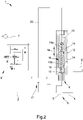
Figure 2 is the hydraulic diagram ofFigure 1 with the first valve means shown in section. - With particular reference to these figures, reference numeral 1 globally indicates a device for damping inertial stresses.
- The device 1 comprises at least one
feeding line 2 of a pressurized work fluid, at least onelifting apparatus 3 for lifting at least one working implement (not shown in the illustrations), provided with at least oneactuation element 4 and with at least onethrust chamber 5 communicating with thefeeding line 2 and adapted to move theactuation element 4 due to the effect of the variation in pressure of the work fluid inside it, and at least onedrain line 6 of the work fluid. - Conveniently, the
lifting apparatus 3 comprises a leverage system for controlling the position of the working implement. - The
feeding line 2 is connectable to pumping means 7 for pumping the work fluid and pressure adjustment means 8 are provided, e.g., of the type of a plurality of distributors connected to each other in a fluid-operated manner, along thefeeding line 2. The pumping means 7 and the adjustment means 8 are not part of the present invention. - According to the invention, the device 1 comprises valve means 9, 17 interposed between the
feeding line 2 and thedrain line 6 and adapted to place these in communication with each other as a result of a predefined pressure increase inside thethrust chamber 5. - By effect of the connection between the
feeding line 2 and the drain line 6 a pressure reduction is obtained and along the feeding line itself which, by means of the reverse movement of theactuation element 4, causes the lowering of the working implement. The movement of the working implement makes it possible to counteract the inertial forces generated by the jerky movement of the vehicle. - According to the invention, the valve means 9, 17 comprise first valve means 9 interposed between the
feeding line 2 and thedrain line 6 and adapted to place them in communication with each other when achieving the predefined pressure increase, at least onepiloting line 22 acting on the first valve means 9 and second valve means 17 which can be commanded in order to place in communication/isolate thepiloting line 22 with/from thefeeding line 2. - According to the invention, the first valve means 9 comprise at least one
body 10 in which is formed at least oneseat 11 which is provided with at least afirst port 12 communicating with thefeeding line 2, with at least asecond port 13 communicating with thepiloting line 22 and with at least athird port 14 communicating with thedrain line 6. - The first and the
second port seat 11. - Inside the
seat 11 is housed at least oneshutter 15, placed facing thefirst port 12 and moveable between a closing position and an opening position of the first port itself. - Inside the
seat 11 is also housed at least onepiloting element 16, positioned facing thesecond port 13 and adapted to push theshutter 15 towards the closing position. Theshutter 15 is adapted to be displaced to the opening position as a result of the predefined pressure increase mentioned above along thefeeding line 2 and of the isolation of thepiloting line 22 from the feeding line itself. More in detail, after thesecond port 13 has been isolated from thefeeding line 2, by means of the second valve means 17, the pressure applied by the work fluid on thepiloting element 16, and therefore by the latter on theshutter 15, is fixed. Theshutter 15 is therefore able to move from the closing position to the opening position when there is an overpressure along thefeeding line 2, e.g. due to an increase in the pressure present in thethrust chamber 5, such as to overcome the force applied by thepiloting element 16. - In the opening position of the
shutter 15, thefirst port 12 is placed in communication with thethird port 14, so that one part of the work fluid present along thefeeding line 2 reaches thedrain line 6, thus reducing the pressure inside thethrust chamber 5. - According to the invention, the device 1 comprises second valve means 17, interposed between the
feeding line 2 and thepiloting line 22 and operable to open / close the fluid-operated connection between these. - More in particular, the second valve means 17 are of the type of a tap having two work positions, i.e. a first position, in which the
piloting line 22 is placed in communication with thefeeding line 2, and a second position, in which thepiloting line 22 is isolated from thefeeding line 2. In the first position of thetap 17 the work fluid enters inside thebody 10 and operates on thepiloting element 16 by applying a force thereon, while in the second position (active system), the fluid-operated connection between thefeeding line 2 and thepiloting line 22 is interrupted, so that the work fluid previously entered into thesecond port 13 operates on thepiloting element 16. When thetap 17 is in the second work position, the force that the work fluid applies on thepiloting element 16 is no longer affected by the pressure variations occurring along thefeeding line 2, so it remains substantially unaltered. - In the embodiment shown in the illustrations, the
second port 13 has a larger area than thefirst port 12. Pressure being equal, the work fluid applies a greater force on thepiloting element 16 than on theshutter 15. - Suitably, the
piloting element 16 comprises at least onethrust element 16a arranged facing thesecond port 13 and moveable in translation along a flowingdirection 18 according to the pressure of the work fluid along thefeeding line 2. In particular, when the second valve means 17 are in the first work position, thethrust element 16a moves along the flowingdirection 18, towards or away from theshutter 15, due to an increase and decrease respectively in the pressure of the work fluid present along thefeeding line 2. - Depending on the direction of movement of the
thrust element 16a, the force applied by thethrust element 16a on theshutter 15 therefore changes. Advantageously, thepiloting element 16 compriseselastic means 16b interposed between thethrust element 16a and theshutter 15, where thethrust element 16a is adapted to interact with theelastic means 16b as a result of the displacement thereof along the flowingdirection 18, so as to vary the force which the elastic means themselves apply on theshutter 15. - Preferably, the elastic means 16b are of the pre-compressed type.
- Between the
third port 14 and thedrain line 6 is interposed at least one connecting section, identified withreference numeral 19 inFigure 1 , along which is arranged at least afirst restriction 20. - Conveniently, the device 1 comprises at least a
second restriction 21 arranged along thefeeding line 2 and interposed between thethrust chamber 5 and the valve means 9 and 17. - More in particular, the
first restriction 20 and thesecond restriction 21 permit limiting the flow rate of the work fluid coming out of thethrust chamber 5, so as to obtain the instantaneous lowering of the working implement which is at the same time gradual and limited. - The operation of the present invention is as follows.
- Whenever it becomes necessary to transport the working implement carried by the agricultural vehicle, the
lifting apparatus 3 is operated so as to lift the working implement itself, conveying work fluid under pressure inside thethrust chamber 5 by means of the pumping means 7 and the pressure adjustment means 8. - The working implement is then kept in raised position while maintaining the
thrust chamber 5 under pressure. As can be easily appreciated, the pressure of the work fluid inside thethrust chamber 5 is proportional to the load lifted by theactuation element 4. This pressure is therefore considered as the nominal transport pressure. - In this phase, the work fluid present along the
feeding line 2 enters thefirst port 12, and starts to operate on theshutter 15. - At the same time, the second valve means 17 are arranged in the first work position and the work fluid present along the
feeding line 2 also runs along thepiloting line 22 and enters thesecond port 13 starting to operate on thepiloting element 16. - More in particular, the work fluid entering through the
second port 13 applies a force on thethrust element 16a such as to move it along the flowingdirection 18 so as to compress theelastic means 16b, which in turn apply a force on theshutter 15 keeping it in the closing position. Since the area of thesecond port 13 is larger than that of thefirst port 12, the force applied by the work fluid on thethrust element 16a is greater than that applied on theshutter 15, which therefore remains in the closing position. - Subsequently, the second valve means 17 move to the second work position, so as to isolate the piloting
line 22, and therefore thesecond port 13, from thefeeding line 2. This way, the "calibration" of the first valve means 9 is carried out, inasmuch as by effect of the movement of the second valve means 17 to the second work position, the pressure of the work fluid operating on the pilotingelement 16 remains fixed at the nominal transport value, as it can no longer be affected by the pressure variations along thefeeding line 2. - Whenever the agricultural vehicle runs over any bumps or hollows, due to the stress imposed by the working implement, the pressure inside the
thrust chamber 5 increases and, consequently, so does the pressure of the work fluid along thefeeding line 2. - Such pressure increase causes an increase in the force applied by the work fluid on the
shutter 15. As can be appreciated, theshutter 15 moves from the closing position to the opening position when the force applied by the work fluid on it exceeds the sum of the forces applied in the opposite direction by thethrust element 16a and by theelastic means 16b. - When the
shutter 15 reaches the opening position, the work fluid present along thefeeding line 2 then enters theseat 11 and flows out of thethird port 14 to reach thedrain line 6. - The flow of the work fluid into the
drain line 6 thus causes a reduction in pressure along thefeeding line 2 and, consequently, inside thethrust chamber 5, as a result of which theactuation element 4 moves and lowers the working implement. - The movement of the
lifting apparatus 3 and the consequent lowering of the working implement makes it possible to dampen the inertial forces generated by the stresses caused by the roughness of the ground. As described above, therestrictions actuation element 4 is returned to the starting position by conveying work fluid under pressure into thethrust chamber 5. - It has in practice been ascertained that the described invention achieves the intended objects and, in particular, the fact is underlined that the first valve means allow discharging a part of the work fluid contained in the thrust chamber of the actuation element following the occurrence of a predefined overpressure inside it.
- More in particular, by activating the device forming the subject of the present invention, the force operating on the piloting element is calibrated from time to time at the nominal transport pressure, and in this way it is possible to obtain the automatic opening of the shutter when the pressure of the work fluid inside the thrust chamber exceeds the nominal transport pressure by a predefined value.
- The device forming the subject of the present invention therefore adapts by itself to the weight of the load applied to the lifting device and permits lowering the working implement to offset the inertial forces generated in the event of abnormal stresses upon reaching a predefined pressure peak inside the thrust chamber of the lifting device itself.
Claims (8)
- Device (1) for damping the stresses of agricultural vehicles, comprising:- at least one feeding line (2) of a pressurized work fluid;- at least one lifting apparatus (3) for lifting at least one work tool, provided with at least one actuation element (4) and with at least one thrust chamber (5) communicating with said feeding line (2) and adapted to move said actuation element (4) due to the effect of the variation in pressure of the work fluid inside it;- at least one drain line (6) of the work fluid;- valve means (9, 17) interposed between said feeding line (2) and said drain line (6) and configured to place them in communication with each other as a result of a predefined pressure increase inside said thrust chamber (5), wherein said valve means (9, 17) comprise first valve means (9) interposed between said feeding line (2) and said drain line (6) and adapted to place them in communication with each other when achieving said predefined pressure increase, at least one piloting line (22) acting on said first valve means (9) and second valve means (17) which can be commanded in order to place in communication/isolate said piloting line (22) with/from said feeding line (2), characterized by the fact that said first valve means (9) comprise at least one body (10) in which at least one seat (11) is formed, provided with at least a first port (12) communicating with said feeding line (2), with at least a second port (13) communicating with said piloting line (22) and with at least a third port (14) communicating with said drain line (6), where inside said seat (11) is housed at least one shutter (15) placed facing said first port (12) and moveable between a closing position and an opening position of the first port itself, where in the opening position said first port (12) is placed in communication with said third port (14), and at least one piloting element (16) is placed facing said second port (13) and adapted to push said shutter (15) towards the closing position, said shutter (15) displacing to the opening position as a result of said predefined pressure increase and of the isolation of said piloting line (22) from said feeding line (2).
- Device according to claim 1, characterized by the fact that said second valve means (17) are interposed between said feeding line (2) and said piloting line (22) and are operable between a first work position, in which said piloting line (22) is communicating with said feeding line (2), and a second work position, in which said piloting line (22) is isolated from said feeding line (2).
- Device (1) according to one or more of the preceding claims, characterized by the fact that said second port (13) has a greater area with respect to said first port (12).
- Device (1) according to one or more of the preceding claims5, characterized by the fact that said piloting element (16) comprises at least one thrust element (16a) arranged facing said second port (13) and moveable in translation along a flowing direction (18) due to the effect of the variation in pressure along said feeding line (2).
- Device (1) according to claim 4, characterized by the fact that said piloting element (16) comprises elastic means (16b) interposed between said thrust element (16a) and said shutter (15), said thrust element (16a) being adapted to interact with said elastic means (16b) as a result of the displacement thereof along said flowing direction (18).
- Device (1) according to claim 5, characterized by the fact that said elastic means (16b) are of the pre-compressed type.
- Device (1) according to one or more of the preceding claims, characterized by the fact that it comprises at least one connecting section (19) interposed between said third port (14) and said drain line (6) and by the fact of comprising at least a first restriction (20) arranged along said connecting section (19).
- Device (1) according to one or more of the preceding claims, characterized by the fact that it comprises at least a second restriction (21) arranged along said feeding line and interposed between said thrust chamber (5) and said valve means (9, 17).
Applications Claiming Priority (2)
| Application Number | Priority Date | Filing Date | Title |
|---|---|---|---|
| IT201700130300 | 2017-11-15 | ||
| PCT/IB2018/058871 WO2019097391A1 (en) | 2017-11-15 | 2018-11-12 | Device for damping the inertial stresses |
Publications (2)
| Publication Number | Publication Date |
|---|---|
| EP3709785A1 EP3709785A1 (en) | 2020-09-23 |
| EP3709785B1 true EP3709785B1 (en) | 2022-09-14 |
Family
ID=61527275
Family Applications (1)
| Application Number | Title | Priority Date | Filing Date |
|---|---|---|---|
| EP18822483.6A Active EP3709785B1 (en) | 2017-11-15 | 2018-11-12 | Device for damping the inertial stresses |
Country Status (3)
| Country | Link |
|---|---|
| EP (1) | EP3709785B1 (en) |
| CN (1) | CN111356354B (en) |
| WO (1) | WO2019097391A1 (en) |
Cited By (1)
| Publication number | Priority date | Publication date | Assignee | Title |
|---|---|---|---|---|
| EP4699425A1 (en) * | 2024-08-20 | 2026-02-25 | Noremat | Three-point hitch with hydraulic shock absorber |
Families Citing this family (1)
| Publication number | Priority date | Publication date | Assignee | Title |
|---|---|---|---|---|
| IT202300014940A1 (en) * | 2023-07-17 | 2025-01-17 | Mita Oleodinamica Spa | EQUIPMENT FOR CONTROLLING THE MOVEMENT OF A WORK TOOL OF AN AGRICULTURAL VEHICLE |
Family Cites Families (7)
| Publication number | Priority date | Publication date | Assignee | Title |
|---|---|---|---|---|
| DD126376A1 (en) * | 1976-06-11 | 1977-07-13 | ||
| DE2856583C2 (en) * | 1978-12-22 | 1985-02-07 | Alfred Dipl.-Ing. 1000 Berlin Ulrich | Three-point hitch for a tractor with a rear and / or front attachment |
| US5884204A (en) * | 1996-04-16 | 1999-03-16 | Case Corporation | Active roadability control for work vehicles |
| CN2810128Y (en) * | 2005-07-19 | 2006-08-30 | 山东福田重工股份有限公司 | Hoister for tractor |
| JP2013103516A (en) * | 2011-11-10 | 2013-05-30 | Toyota Motor Corp | Vehicle and control method for vehicle |
| DE102015218330A1 (en) * | 2015-09-24 | 2017-03-30 | Robert Bosch Gmbh | Apparatus and method for controlling the operation of a hydraulically operated towed vehicle on a vehicle |
| DK179447B1 (en) * | 2015-12-17 | 2018-10-11 | Agro Intelligence Aps | A coupling mechanism and use of a coupling mechanism for damping oscillations between a tractor and an agricultural implement during transport thereof |
-
2018
- 2018-11-12 CN CN201880073860.4A patent/CN111356354B/en active Active
- 2018-11-12 EP EP18822483.6A patent/EP3709785B1/en active Active
- 2018-11-12 WO PCT/IB2018/058871 patent/WO2019097391A1/en not_active Ceased
Cited By (2)
| Publication number | Priority date | Publication date | Assignee | Title |
|---|---|---|---|---|
| EP4699425A1 (en) * | 2024-08-20 | 2026-02-25 | Noremat | Three-point hitch with hydraulic shock absorber |
| FR3165667A1 (en) * | 2024-08-20 | 2026-02-27 | Noremat | Three-point hitch with hydraulic shock absorber |
Also Published As
| Publication number | Publication date |
|---|---|
| CN111356354A (en) | 2020-06-30 |
| EP3709785A1 (en) | 2020-09-23 |
| CN111356354B (en) | 2022-10-28 |
| WO2019097391A1 (en) | 2019-05-23 |
Similar Documents
| Publication | Publication Date | Title |
|---|---|---|
| US7448309B2 (en) | Hydraulic arrangement | |
| US9683587B2 (en) | Fluid pressure control device | |
| GB2440610A (en) | Component failure protection valve with overpressure opening | |
| AU2018202033B2 (en) | Systems and methods for mast stabilization on a material handling vehicle | |
| EP2031256A2 (en) | Lifting device and method for operating a lifting device | |
| CN108328524B (en) | Variable hydraulic pressure unloading system and method for a material handling vehicle | |
| JP2004534188A (en) | Hydraulic pressure control device | |
| WO2019097391A1 (en) | Device for damping the inertial stresses | |
| KR20110097795A (en) | Device for compensating hydraulic effective pressure | |
| EP3312436B1 (en) | Anti-rupture tube device | |
| EP2786959B1 (en) | Anti cavitation device for a hydraulic cylinder | |
| EP3228580B1 (en) | A control device of an actuator | |
| MX2015004964A (en) | System preventing pressured oil leakage to cylinder line in control valve systems with flow divider. | |
| EP2786958B1 (en) | Control device for the descent of a load | |
| EP3557083B1 (en) | Tube rupture protection device | |
| EP1114956B1 (en) | An overpressure valve | |
| US20200141429A1 (en) | A control valve for hydraulic lifters | |
| EP1347103A2 (en) | Control of an operating arm of an earthmoving vehicle | |
| JP2015001249A (en) | Hydraulic control device | |
| JP4963712B2 (en) | Overload prevention device | |
| US9869359B2 (en) | Hydraulic system with an unloading valve | |
| EP3513079B1 (en) | Valve for a single-acting cylinder and its assembly in a motor vehicle's tipper body | |
| EP3137779B1 (en) | Pressure limiting device | |
| HK1259558A1 (en) | Systems and methods for mast stabilization on a material handling vehicle | |
| WO2021168127A1 (en) | Hydraulic control system and method with electro-proportional pressure valve and integral check |
Legal Events
| Date | Code | Title | Description |
|---|---|---|---|
| STAA | Information on the status of an ep patent application or granted ep patent |
Free format text: STATUS: UNKNOWN |
|
| STAA | Information on the status of an ep patent application or granted ep patent |
Free format text: STATUS: THE INTERNATIONAL PUBLICATION HAS BEEN MADE |
|
| PUAI | Public reference made under article 153(3) epc to a published international application that has entered the european phase |
Free format text: ORIGINAL CODE: 0009012 |
|
| STAA | Information on the status of an ep patent application or granted ep patent |
Free format text: STATUS: REQUEST FOR EXAMINATION WAS MADE |
|
| 17P | Request for examination filed |
Effective date: 20200612 |
|
| AK | Designated contracting states |
Kind code of ref document: A1 Designated state(s): AL AT BE BG CH CY CZ DE DK EE ES FI FR GB GR HR HU IE IS IT LI LT LU LV MC MK MT NL NO PL PT RO RS SE SI SK SM TR |
|
| AX | Request for extension of the european patent |
Extension state: BA ME |
|
| DAV | Request for validation of the european patent (deleted) | ||
| DAX | Request for extension of the european patent (deleted) | ||
| GRAP | Despatch of communication of intention to grant a patent |
Free format text: ORIGINAL CODE: EPIDOSNIGR1 |
|
| STAA | Information on the status of an ep patent application or granted ep patent |
Free format text: STATUS: GRANT OF PATENT IS INTENDED |
|
| INTG | Intention to grant announced |
Effective date: 20220408 |
|
| GRAS | Grant fee paid |
Free format text: ORIGINAL CODE: EPIDOSNIGR3 |
|
| GRAA | (expected) grant |
Free format text: ORIGINAL CODE: 0009210 |
|
| STAA | Information on the status of an ep patent application or granted ep patent |
Free format text: STATUS: THE PATENT HAS BEEN GRANTED |
|
| AK | Designated contracting states |
Kind code of ref document: B1 Designated state(s): AL AT BE BG CH CY CZ DE DK EE ES FI FR GB GR HR HU IE IS IT LI LT LU LV MC MK MT NL NO PL PT RO RS SE SI SK SM TR |
|
| REG | Reference to a national code |
Ref country code: GB Ref legal event code: FG4D |
|
| REG | Reference to a national code |
Ref country code: CH Ref legal event code: EP |
|
| REG | Reference to a national code |
Ref country code: DE Ref legal event code: R096 Ref document number: 602018040739 Country of ref document: DE |
|
| REG | Reference to a national code |
Ref country code: IE Ref legal event code: FG4D |
|
| REG | Reference to a national code |
Ref country code: AT Ref legal event code: REF Ref document number: 1518134 Country of ref document: AT Kind code of ref document: T Effective date: 20221015 |
|
| REG | Reference to a national code |
Ref country code: LT Ref legal event code: MG9D |
|
| REG | Reference to a national code |
Ref country code: NL Ref legal event code: MP Effective date: 20220914 |
|
| PG25 | Lapsed in a contracting state [announced via postgrant information from national office to epo] |
Ref country code: SE Free format text: LAPSE BECAUSE OF FAILURE TO SUBMIT A TRANSLATION OF THE DESCRIPTION OR TO PAY THE FEE WITHIN THE PRESCRIBED TIME-LIMIT Effective date: 20220914 Ref country code: RS Free format text: LAPSE BECAUSE OF FAILURE TO SUBMIT A TRANSLATION OF THE DESCRIPTION OR TO PAY THE FEE WITHIN THE PRESCRIBED TIME-LIMIT Effective date: 20220914 Ref country code: NO Free format text: LAPSE BECAUSE OF FAILURE TO SUBMIT A TRANSLATION OF THE DESCRIPTION OR TO PAY THE FEE WITHIN THE PRESCRIBED TIME-LIMIT Effective date: 20221214 Ref country code: LV Free format text: LAPSE BECAUSE OF FAILURE TO SUBMIT A TRANSLATION OF THE DESCRIPTION OR TO PAY THE FEE WITHIN THE PRESCRIBED TIME-LIMIT Effective date: 20220914 Ref country code: LT Free format text: LAPSE BECAUSE OF FAILURE TO SUBMIT A TRANSLATION OF THE DESCRIPTION OR TO PAY THE FEE WITHIN THE PRESCRIBED TIME-LIMIT Effective date: 20220914 Ref country code: FI Free format text: LAPSE BECAUSE OF FAILURE TO SUBMIT A TRANSLATION OF THE DESCRIPTION OR TO PAY THE FEE WITHIN THE PRESCRIBED TIME-LIMIT Effective date: 20220914 |
|
| REG | Reference to a national code |
Ref country code: AT Ref legal event code: MK05 Ref document number: 1518134 Country of ref document: AT Kind code of ref document: T Effective date: 20220914 |
|
| PG25 | Lapsed in a contracting state [announced via postgrant information from national office to epo] |
Ref country code: HR Free format text: LAPSE BECAUSE OF FAILURE TO SUBMIT A TRANSLATION OF THE DESCRIPTION OR TO PAY THE FEE WITHIN THE PRESCRIBED TIME-LIMIT Effective date: 20220914 Ref country code: GR Free format text: LAPSE BECAUSE OF FAILURE TO SUBMIT A TRANSLATION OF THE DESCRIPTION OR TO PAY THE FEE WITHIN THE PRESCRIBED TIME-LIMIT Effective date: 20221215 |
|
| REG | Reference to a national code |
Ref country code: DE Ref legal event code: R082 Ref document number: 602018040739 Country of ref document: DE Representative=s name: WOERZ PATENTANWAELTE PARTNERSCHAFTSGESELLSCHAF, DE |
|
| PG25 | Lapsed in a contracting state [announced via postgrant information from national office to epo] |
Ref country code: SM Free format text: LAPSE BECAUSE OF FAILURE TO SUBMIT A TRANSLATION OF THE DESCRIPTION OR TO PAY THE FEE WITHIN THE PRESCRIBED TIME-LIMIT Effective date: 20220914 Ref country code: RO Free format text: LAPSE BECAUSE OF FAILURE TO SUBMIT A TRANSLATION OF THE DESCRIPTION OR TO PAY THE FEE WITHIN THE PRESCRIBED TIME-LIMIT Effective date: 20220914 Ref country code: PT Free format text: LAPSE BECAUSE OF FAILURE TO SUBMIT A TRANSLATION OF THE DESCRIPTION OR TO PAY THE FEE WITHIN THE PRESCRIBED TIME-LIMIT Effective date: 20230116 Ref country code: ES Free format text: LAPSE BECAUSE OF FAILURE TO SUBMIT A TRANSLATION OF THE DESCRIPTION OR TO PAY THE FEE WITHIN THE PRESCRIBED TIME-LIMIT Effective date: 20220914 Ref country code: CZ Free format text: LAPSE BECAUSE OF FAILURE TO SUBMIT A TRANSLATION OF THE DESCRIPTION OR TO PAY THE FEE WITHIN THE PRESCRIBED TIME-LIMIT Effective date: 20220914 Ref country code: AT Free format text: LAPSE BECAUSE OF FAILURE TO SUBMIT A TRANSLATION OF THE DESCRIPTION OR TO PAY THE FEE WITHIN THE PRESCRIBED TIME-LIMIT Effective date: 20220914 |
|
| PG25 | Lapsed in a contracting state [announced via postgrant information from national office to epo] |
Ref country code: SK Free format text: LAPSE BECAUSE OF FAILURE TO SUBMIT A TRANSLATION OF THE DESCRIPTION OR TO PAY THE FEE WITHIN THE PRESCRIBED TIME-LIMIT Effective date: 20220914 Ref country code: PL Free format text: LAPSE BECAUSE OF FAILURE TO SUBMIT A TRANSLATION OF THE DESCRIPTION OR TO PAY THE FEE WITHIN THE PRESCRIBED TIME-LIMIT Effective date: 20220914 Ref country code: IS Free format text: LAPSE BECAUSE OF FAILURE TO SUBMIT A TRANSLATION OF THE DESCRIPTION OR TO PAY THE FEE WITHIN THE PRESCRIBED TIME-LIMIT Effective date: 20230114 Ref country code: EE Free format text: LAPSE BECAUSE OF FAILURE TO SUBMIT A TRANSLATION OF THE DESCRIPTION OR TO PAY THE FEE WITHIN THE PRESCRIBED TIME-LIMIT Effective date: 20220914 |
|
| REG | Reference to a national code |
Ref country code: DE Ref legal event code: R097 Ref document number: 602018040739 Country of ref document: DE |
|
| PG25 | Lapsed in a contracting state [announced via postgrant information from national office to epo] |
Ref country code: NL Free format text: LAPSE BECAUSE OF FAILURE TO SUBMIT A TRANSLATION OF THE DESCRIPTION OR TO PAY THE FEE WITHIN THE PRESCRIBED TIME-LIMIT Effective date: 20220914 Ref country code: MC Free format text: LAPSE BECAUSE OF FAILURE TO SUBMIT A TRANSLATION OF THE DESCRIPTION OR TO PAY THE FEE WITHIN THE PRESCRIBED TIME-LIMIT Effective date: 20220914 Ref country code: AL Free format text: LAPSE BECAUSE OF FAILURE TO SUBMIT A TRANSLATION OF THE DESCRIPTION OR TO PAY THE FEE WITHIN THE PRESCRIBED TIME-LIMIT Effective date: 20220914 |
|
| REG | Reference to a national code |
Ref country code: CH Ref legal event code: PL |
|
| P01 | Opt-out of the competence of the unified patent court (upc) registered |
Effective date: 20230527 |
|
| PLBE | No opposition filed within time limit |
Free format text: ORIGINAL CODE: 0009261 |
|
| STAA | Information on the status of an ep patent application or granted ep patent |
Free format text: STATUS: NO OPPOSITION FILED WITHIN TIME LIMIT |
|
| REG | Reference to a national code |
Ref country code: BE Ref legal event code: MM Effective date: 20221130 |
|
| PG25 | Lapsed in a contracting state [announced via postgrant information from national office to epo] |
Ref country code: LI Free format text: LAPSE BECAUSE OF NON-PAYMENT OF DUE FEES Effective date: 20221130 Ref country code: DK Free format text: LAPSE BECAUSE OF FAILURE TO SUBMIT A TRANSLATION OF THE DESCRIPTION OR TO PAY THE FEE WITHIN THE PRESCRIBED TIME-LIMIT Effective date: 20220914 Ref country code: CH Free format text: LAPSE BECAUSE OF NON-PAYMENT OF DUE FEES Effective date: 20221130 |
|
| 26N | No opposition filed |
Effective date: 20230615 |
|
| GBPC | Gb: european patent ceased through non-payment of renewal fee |
Effective date: 20221214 |
|
| PG25 | Lapsed in a contracting state [announced via postgrant information from national office to epo] |
Ref country code: SI Free format text: LAPSE BECAUSE OF FAILURE TO SUBMIT A TRANSLATION OF THE DESCRIPTION OR TO PAY THE FEE WITHIN THE PRESCRIBED TIME-LIMIT Effective date: 20220914 Ref country code: LU Free format text: LAPSE BECAUSE OF NON-PAYMENT OF DUE FEES Effective date: 20221112 |
|
| PG25 | Lapsed in a contracting state [announced via postgrant information from national office to epo] |
Ref country code: IE Free format text: LAPSE BECAUSE OF NON-PAYMENT OF DUE FEES Effective date: 20221112 Ref country code: GB Free format text: LAPSE BECAUSE OF NON-PAYMENT OF DUE FEES Effective date: 20221214 |
|
| PG25 | Lapsed in a contracting state [announced via postgrant information from national office to epo] |
Ref country code: FR Free format text: LAPSE BECAUSE OF NON-PAYMENT OF DUE FEES Effective date: 20221114 Ref country code: BE Free format text: LAPSE BECAUSE OF NON-PAYMENT OF DUE FEES Effective date: 20221130 |
|
| PG25 | Lapsed in a contracting state [announced via postgrant information from national office to epo] |
Ref country code: CY Free format text: LAPSE BECAUSE OF FAILURE TO SUBMIT A TRANSLATION OF THE DESCRIPTION OR TO PAY THE FEE WITHIN THE PRESCRIBED TIME-LIMIT Effective date: 20220914 |
|
| PG25 | Lapsed in a contracting state [announced via postgrant information from national office to epo] |
Ref country code: MK Free format text: LAPSE BECAUSE OF FAILURE TO SUBMIT A TRANSLATION OF THE DESCRIPTION OR TO PAY THE FEE WITHIN THE PRESCRIBED TIME-LIMIT Effective date: 20220914 Ref country code: HU Free format text: LAPSE BECAUSE OF FAILURE TO SUBMIT A TRANSLATION OF THE DESCRIPTION OR TO PAY THE FEE WITHIN THE PRESCRIBED TIME-LIMIT; INVALID AB INITIO Effective date: 20181112 |
|
| PG25 | Lapsed in a contracting state [announced via postgrant information from national office to epo] |
Ref country code: BG Free format text: LAPSE BECAUSE OF FAILURE TO SUBMIT A TRANSLATION OF THE DESCRIPTION OR TO PAY THE FEE WITHIN THE PRESCRIBED TIME-LIMIT Effective date: 20220914 |
|
| PG25 | Lapsed in a contracting state [announced via postgrant information from national office to epo] |
Ref country code: MT Free format text: LAPSE BECAUSE OF FAILURE TO SUBMIT A TRANSLATION OF THE DESCRIPTION OR TO PAY THE FEE WITHIN THE PRESCRIBED TIME-LIMIT Effective date: 20220914 |
|
| PGFP | Annual fee paid to national office [announced via postgrant information from national office to epo] |
Ref country code: DE Payment date: 20251128 Year of fee payment: 8 |
|
| PGFP | Annual fee paid to national office [announced via postgrant information from national office to epo] |
Ref country code: IT Payment date: 20251119 Year of fee payment: 8 |
|
| PGFP | Annual fee paid to national office [announced via postgrant information from national office to epo] |
Ref country code: TR Payment date: 20251023 Year of fee payment: 8 |