EP3709735B1 - Procédé de communication, dispositif terminal et dispositif de réseau mettant en uvre celui-ci - Google Patents
Procédé de communication, dispositif terminal et dispositif de réseau mettant en uvre celui-ci Download PDFInfo
- Publication number
- EP3709735B1 EP3709735B1 EP18877862.5A EP18877862A EP3709735B1 EP 3709735 B1 EP3709735 B1 EP 3709735B1 EP 18877862 A EP18877862 A EP 18877862A EP 3709735 B1 EP3709735 B1 EP 3709735B1
- Authority
- EP
- European Patent Office
- Prior art keywords
- carrier
- uplink
- random access
- uplink carrier
- resource
- Prior art date
- Legal status (The legal status is an assumption and is not a legal conclusion. Google has not performed a legal analysis and makes no representation as to the accuracy of the status listed.)
- Active
Links
Images


Classifications
-
- H—ELECTRICITY
- H04—ELECTRIC COMMUNICATION TECHNIQUE
- H04L—TRANSMISSION OF DIGITAL INFORMATION, e.g. TELEGRAPHIC COMMUNICATION
- H04L5/00—Arrangements affording multiple use of the transmission path
- H04L5/003—Arrangements for allocating sub-channels of the transmission path
- H04L5/0048—Allocation of pilot signals, i.e. of signals known to the receiver
-
- H—ELECTRICITY
- H04—ELECTRIC COMMUNICATION TECHNIQUE
- H04W—WIRELESS COMMUNICATION NETWORKS
- H04W72/00—Local resource management
- H04W72/04—Wireless resource allocation
- H04W72/044—Wireless resource allocation based on the type of the allocated resource
- H04W72/0453—Resources in frequency domain, e.g. a carrier in FDMA
-
- H—ELECTRICITY
- H04—ELECTRIC COMMUNICATION TECHNIQUE
- H04L—TRANSMISSION OF DIGITAL INFORMATION, e.g. TELEGRAPHIC COMMUNICATION
- H04L5/00—Arrangements affording multiple use of the transmission path
- H04L5/0001—Arrangements for dividing the transmission path
- H04L5/0003—Two-dimensional division
- H04L5/0005—Time-frequency
- H04L5/0007—Time-frequency the frequencies being orthogonal, e.g. OFDM(A) or DMT
- H04L5/001—Time-frequency the frequencies being orthogonal, e.g. OFDM(A) or DMT the frequencies being arranged in component carriers
-
- H—ELECTRICITY
- H04—ELECTRIC COMMUNICATION TECHNIQUE
- H04L—TRANSMISSION OF DIGITAL INFORMATION, e.g. TELEGRAPHIC COMMUNICATION
- H04L5/00—Arrangements affording multiple use of the transmission path
- H04L5/003—Arrangements for allocating sub-channels of the transmission path
- H04L5/0053—Allocation of signalling, i.e. of overhead other than pilot signals
-
- H—ELECTRICITY
- H04—ELECTRIC COMMUNICATION TECHNIQUE
- H04L—TRANSMISSION OF DIGITAL INFORMATION, e.g. TELEGRAPHIC COMMUNICATION
- H04L5/00—Arrangements affording multiple use of the transmission path
- H04L5/0091—Signalling for the administration of the divided path, e.g. signalling of configuration information
- H04L5/0094—Indication of how sub-channels of the path are allocated
-
- H—ELECTRICITY
- H04—ELECTRIC COMMUNICATION TECHNIQUE
- H04W—WIRELESS COMMUNICATION NETWORKS
- H04W72/00—Local resource management
- H04W72/02—Selection of wireless resources by user or terminal
-
- H—ELECTRICITY
- H04—ELECTRIC COMMUNICATION TECHNIQUE
- H04W—WIRELESS COMMUNICATION NETWORKS
- H04W72/00—Local resource management
- H04W72/20—Control channels or signalling for resource management
- H04W72/21—Control channels or signalling for resource management in the uplink direction of a wireless link, i.e. towards the network
-
- H—ELECTRICITY
- H04—ELECTRIC COMMUNICATION TECHNIQUE
- H04W—WIRELESS COMMUNICATION NETWORKS
- H04W72/00—Local resource management
- H04W72/20—Control channels or signalling for resource management
- H04W72/23—Control channels or signalling for resource management in the downlink direction of a wireless link, i.e. towards a terminal
-
- H—ELECTRICITY
- H04—ELECTRIC COMMUNICATION TECHNIQUE
- H04W—WIRELESS COMMUNICATION NETWORKS
- H04W72/00—Local resource management
- H04W72/50—Allocation or scheduling criteria for wireless resources
- H04W72/54—Allocation or scheduling criteria for wireless resources based on quality criteria
- H04W72/542—Allocation or scheduling criteria for wireless resources based on quality criteria using measured or perceived quality
-
- H—ELECTRICITY
- H04—ELECTRIC COMMUNICATION TECHNIQUE
- H04W—WIRELESS COMMUNICATION NETWORKS
- H04W74/00—Wireless channel access
- H04W74/08—Non-scheduled access, e.g. ALOHA
- H04W74/0833—Random access procedures, e.g. with 4-step access
- H04W74/0838—Random access procedures, e.g. with 4-step access using contention-free random access [CFRA]
-
- H—ELECTRICITY
- H04—ELECTRIC COMMUNICATION TECHNIQUE
- H04W—WIRELESS COMMUNICATION NETWORKS
- H04W74/00—Wireless channel access
- H04W74/08—Non-scheduled access, e.g. ALOHA
- H04W74/0866—Non-scheduled access, e.g. ALOHA using a dedicated channel for access
-
- H—ELECTRICITY
- H04—ELECTRIC COMMUNICATION TECHNIQUE
- H04W—WIRELESS COMMUNICATION NETWORKS
- H04W74/00—Wireless channel access
- H04W74/08—Non-scheduled access, e.g. ALOHA
- H04W74/0833—Random access procedures, e.g. with 4-step access
Definitions
- This disclosure relates to the communications field, and more specifically, to a communication method, a terminal device, and a network device in the communications field.
- a conventional cell includes one downlink carrier and one uplink carrier, and in the conventional cell, a frequency of the uplink carrier is the same as or similar to a frequency of the downlink carrier.
- a new radio New Radio, NR
- an operating frequency band of the high-frequency cell is relatively high and transmit power of a terminal device is relatively low, so that a terminal device located in an edge area of the cell can receive a signal of a base station to which the cell belongs, but the base station cannot receive a signal of the terminal device in the edge area, in other words, uplink coverage and downlink coverage are asymmetric.
- the uplink frequency band of the lower frequency may be referred to as a supplementary uplink (Supplementary Uplink, SUL) carrier.
- SUL Supplemental Uplink
- the additional uplink frequency band has smaller signal attenuation, the uplink coverage can be expanded, so that the uplink coverage can be consistent with the downlink coverage.
- a 1.8 GHz uplink frequency band, a 3.5 GHz uplink frequency band, and a 3.5 GHz downlink frequency band may be used.
- this is not limited, and a deployment solution of another frequency band may be alternatively used. Therefore, when there are a plurality of uplink frequency bands in a cell, how the terminal device selects a carrier (that is, selecting a resource) when accessing the cell and how a network device performs resource configuration is an issue to be resolved urgently.
- CMCC "Considerations on support of supplementary uplink frequency", R2-1709093, 3RD GENERATION PARTNERSHIP PROJECT (3GPP) , describes that two sets of uplink resource information should be broadcast in system information for both SUL frequency and NR normal uplink frequency, including uplink carrier frequency, uplink bandwidth and common uplink configuration information, and three candidate solutions about how the UE to select the PRACH resources from the two uplink frequencies (i.e. SUL frequency and NR normal uplink frequency), such as based on gNB configured threshold.
- SUL frequency and NR normal uplink frequency such as based on gNB configured threshold.
- CMCC "Discussion on design of Msg2 for SUL", R1-1717891, 3RD GENERATION PARTNERSHIP PROJECT (3GPP) , describes for the design of PDCCH for Msg.2 under SUL case, the SUL carrier and NR TDD/FDD carrier indexes are introduced into the determination of RA-RNTI in either explicit way or implicit way.
- a plurality of means two or more than two.
- Connection in the examples of this disclosure includes various connection manners such as a direct connection or an indirect connection, to implement communication between devices. This is not limited in the examples of this disclosure.
- FIG 1 is a schematic diagram of cell deployment in an NR system according to an example of this disclosure.
- a region 1 is a downlink coverage area of a high-frequency cell
- a region 2 is an uplink coverage area of the high-frequency cell
- a size of the region 1 is different from a size of the region 2
- the coverage area of the region 2 is less than the coverage area of the region 1.
- transmit power of a network device is usually not limited. Therefore, the network device may use a larger transmit power for sending, to increase a downlink coverage area.
- a terminal device cannot increase an uplink coverage area by increasing a transmit power.
- a downlink carrier in the region 1 may be referred to as an NR downlink (NR Downlink, NR DL) carrier (carrier), and an uplink carrier in the region 2 is referred to as an NR uplink (NR Uplink, NR UL) carrier, a PUL carrier, a normal UL carrier, a common UL carrier, or a non SUL carrier.
- NR Downlink NR DL
- NR Uplink NR Uplink
- a region 3 in FIG 1 is a coverage area of an SUL carrier, and a coverage area of the region 3 is the same as or similar to the coverage area of the region 1.
- the SUL carrier has an uplink frequency band with a frequency lower than that of the common UL carrier. Therefore, signal attenuation in the region 3 is smaller than that in the region 2, and the terminal device may send a signal by using relatively low transmit power.
- the terminal device has two spectrums for uplink transmission. To be specific, the terminal device may perform uplink transmission by using the SUL carrier and the common UL carrier. In other words, a cell that supports SUL configuration has one downlink carrier and two uplink carriers.
- the cell may further include another SUL carrier, in other words, a terminal device in the cell that supports the SUL configuration may perform uplink transmission by using one common UL carrier and at least one SUL carrier.
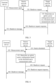
- FIG 2 is an interaction flowchart of a communication method according to an example of this disclosure.
- the communication method may be used in a process in which a terminal device is handed over from a source base station (source gNB) to a target base station (target gNB).
- source gNB source base station
- target gNB target base station
- an NR system is used as an example for description in this example of this disclosure, but the technical solution in this example of this disclosure is not limited to a 5G system.
- a network device/the terminal device may perform some or all of the steps in the foregoing example, and these steps or operations are merely examples. Other operations or variants of the operations may alternatively be performed in this example of this disclosure.
- the steps may be performed in a sequence different from that presented in the foregoing example, and possibly, not all the operations in the foregoing example need to be performed.
- the network device sends indication information to the terminal device, where the indication information is used to indicate resource configuration information of at least one uplink carrier.
- the network device herein is a target network device or a source network device.
- the target network device may be a target base station, namely, the foregoing target gNB
- the source network device may be a source base station, namely, the foregoing source gNB.
- the indication information may be included in a handover request acknowledgement message sent by the target network device to the source network device.
- the source network device sends a handover message to the terminal device.
- the handover message includes the indication information.
- the target network device may first send the indication information to the source network device, and then the source network device transparently transmits the indication information to the terminal device.
- the indication information may be included in a handover response acknowledgement message and the handover message.
- the handover message may be a radio resource control (Radio Resource Control, RRC) connection reconfiguration message including mobility control information (mobility control info), or another message used to instruct the terminal device to be handed over to/change a serving cell/synchronize reconfiguration.
- RRC Radio Resource Control
- the terminal device reports a measurement report to the source network device, and the source network device performs handover determining based on the measurement report reported by the terminal device or based on other information, and determines the target cell to which the terminal device is handed over. Then the terminal device sends a handover request message to the network device (the target network device) to which the target cell belongs. After performing admission control (for example, configuring a resource) based on the received handover request message, the target network device replies the source network device with the handover request acknowledgement message. After receiving the handover request acknowledgement message, the source network device sends the handover message to the terminal device.
- admission control for example, configuring a resource
- the at least one uplink carrier is an uplink carrier in the target cell to which the terminal device is to be handed over, namely, an uplink carrier in a cell of the target network device to which the terminal device is to be handed over.
- the at least one uplink carrier includes a first uplink carrier and/or at least one second uplink carrier, the first uplink carrier and the at least one second uplink carrier are different uplink carriers in the target cell to which the terminal device is to be handed over, and the first uplink carrier and the at least one second uplink carrier are corresponding to one downlink carrier in the target cell.
- the first uplink carrier and the second uplink carrier are uplink carriers with different frequency bands.
- the first uplink carrier may be an uplink carrier with a high frequency band deployed in the NR system, namely, the NR UL carrier, the PUL carrier, the normal UL carrier, or the common UL carrier described above.
- the second uplink carrier is an uplink carrier of a low frequency band (for example, in an LTE system or another communications system), and may be used to assist the terminal device in uplink transmission, namely, the SUL carrier described above. Therefore, in this example of this disclosure, the terminal device may have two spectrums for uplink transmission, and a coverage area of the first uplink carrier is less than a coverage area of the second uplink carrier.
- the coverage area of the first uplink carrier and the coverage area of the second uplink carrier refer to the description in FIG 1 . To avoid repetition, details are not described again.
- a downlink carrier, a first uplink carrier, and at least one second uplink carrier are configured in the target cell, and the first uplink carrier and the at least one second uplink carrier are corresponding to one downlink carrier in the target cell. It may be understood that a coverage area of the downlink carrier is the same as or similar to a coverage area of one of at least one SUL carrier corresponding to the downlink carrier. For example, when there is only one SUL carrier, the coverage area of the downlink carrier is the same as or similar to the coverage area of the SUL carrier.
- a frequency band of the downlink carrier is the same as or similar to a frequency band of the first uplink carrier
- the at least one second uplink carrier is a carrier used to assist the terminal device in uplink transmission, where a frequency band of the at least one second uplink carrier may be lower than that of the downlink carrier or the first uplink carrier.
- the indication information is carried in a reconfiguration message used for synchronization, and the reconfiguration message used for synchronization includes configuration information of the first uplink carrier and configuration information of the second uplink carrier, or the reconfiguration message used for synchronization includes configuration information of the first uplink carrier or configuration information of the second uplink carrier.
- the configuration information of the first uplink carrier includes at least one of a physical uplink shared channel (PUSCH) configuration, a physical uplink control channel (PUCCH) configuration, a sounding reference signal (SRS) configuration, and an uplink power control configuration of the first uplink carrier.
- PUSCH physical uplink shared channel
- PUCCH physical uplink control channel
- SRS sounding reference signal
- the configuration information of the second uplink carrier includes at least one of a physical uplink shared channel (PUSCH) configuration, a physical uplink control channel (PUCCH) configuration, a sounding reference signal (SRS) configuration, and an uplink power control configuration of the second uplink carrier.
- PUSCH physical uplink shared channel
- PUCCH physical uplink control channel
- SRS sounding reference signal
- the resource configuration information includes a dedicated random access resource (dedicated RACH resource).
- the dedicated random access resource may be used by the terminal device to initiate contention-free random access (contention-free random access, contention-free RA/CFRA).
- the dedicated random access resource includes a preamble index (preamble index) and a time-frequency resource.
- the resource configuration information includes the dedicated random access resource
- the target network device may configure one dedicated random access resource for one common UL carrier and/or at least one SUL carrier.
- the target network device may configure the dedicated random access resource for both the common UL carrier and/or the at least one SUL carrier.
- an index value of the SUL carrier is 1.
- a system message, RRC signaling, or a protocol specifies (that is, writing down in a protocol) the index value of the carrier.
- the indication information may include a dedicated random access resource, and a configuration information element of the dedicated random access resource includes the carrier index value 1.
- the indication information is used to indicate that the uplink carrier corresponding to the dedicated random access resource is a SUL carrier #1.
- indication information includes a dedicated random access resource #1, a dedicated random access resource #2, and a dedicated random access resource #3, where a configuration information element of the dedicated random access resource #1 includes a carrier index value 1, in other words, the indication information is used to indicate that the uplink carrier corresponding to the dedicated random access resource #1 is the common UL carrier #1; a configuration information element of the dedicated random access resource #2 includes a carrier index value 2, in other words, the indication information is used to indicate that an uplink carrier corresponding to the dedicated random access resource #2 is the SUL carrier #2; and a configuration information element of the dedicated random access resource #3 includes a carrier index value 4, in other words, the indication information is used to indicate that an uplink carrier corresponding to the dedicated random access resource #3 is the SUL carrier #4.
- the resource configuration information may further include a PUCCH resource.
- the dedicated random access resource there may be a correspondence between the dedicated random access resource and an uplink carrier on which a physical uplink control channel PUCCH resource is configured, that is, the dedicated random access resource is corresponding to the uplink carrier on which the PUCCH resource is configured.
- the indication information may implicitly indicate uplink carriers corresponding to the dedicated random access resource.
- the indication information may include the dedicated random access resource #1, and the network device configures the PUCCH resource for the common UL carrier, the SUL carrier #1, and the SUL carrier #3.
- the network device implicitly indicates that uplink carriers corresponding to the dedicated random access resource #1 are the common UL carrier, the SUL carrier #1, and the SUL carrier #3, that is, the target network device allocates the dedicated random access resource #1 to the common UL carrier, the SUL carrier #1, and the SUL carrier #3.
- an information element for example, ra-PRACH-MaskIndex
- ra-PRACH-MaskIndex may be used to indicate an uplink carrier corresponding to the dedicated random access resource.
- a reserved (reserved) index (index) in the mask index is used for indication.
- the ra-PRACH-MaskIndex may be included in the dedicated random access resource, and configuration information of the dedicated random access resource is included in the handover message.
- a quantity of mask indexes in the ra-PRACH-MaskIndex may be extended, and an extended mask index is used to indicate an uplink carrier corresponding to the dedicated random access resource.
- existing mask indexes are only 0 to 15, and mask indexes used for indication may be directly specified in the protocol.
- a correspondence between a dedicated random access resource and an uplink carrier may be indicated by using the ra-PRACH-MaskIndex.
- a mask index may be used to correspond to a carrier index.
- the dedicated random access resource may be corresponding to any uplink carrier by default.
- the target network device may allocate the dedicated random access resource to the at least one uplink carrier in the foregoing several manners.
- the terminal device may determine, based on the indication information, the at least one uplink carrier corresponding to the dedicated random access resource.
- the resource configuration information may include a common random access resource
- the common random access resource may be for use by the terminal device to initiate contention-based random access (contention-based RA, CBRA).
- the handover message may include a random access channel (RACH) configuration
- the RACH configuration may include the common random access resource.
- the common random access resource is corresponding to one common UL carrier and/or at least one SUL carrier.
- there are a plurality of common random access resources that are respectively corresponding to one common UL carrier and/or at least one SUL carrier.
- the terminal device when the resource configuration information includes the dedicated random access resource, the terminal device preferably initiates random access on the dedicated random access resource.
- the terminal device may initiate random access on the common random access resource.
- the terminal device determines, based on the resource configuration information of the at least one uplink carrier, one uplink carrier from the at least one uplink carrier as a target carrier for performing random access. That is, the target carrier herein is the first uplink carrier or the second uplink carrier described above. In other words, the target carrier is an uplink carrier in a target cell to which the terminal device is to be handed over, to be specific, the target carrier is the common UL carrier or the SUL carrier.
- the resource configuration information includes a dedicated random access resource
- the terminal device determines, based on the indication information, at least one uplink carrier corresponding to the dedicated random access resource.
- the terminal device determines a carrier indicated by the carrier index corresponding to the dedicated random access resource, as the at least one uplink carrier corresponding to the dedicated random access resource.
- the terminal device may determine, based on a mask index indicator bit in the ra-PRACH-MaskIndex, the at least one uplink carrier corresponding to the dedicated random access resource.
- the terminal device may consider by default that the dedicated random access resource may be corresponding to any uplink carrier.
- the terminal device determines the uplink carrier as the target carrier, and initiates random access in the target carrier.
- the target network device configures the dedicated random access resource only for one uplink carrier (to be specific, the common UL carrier or the SUL carrier); the terminal device initiates random access by using a dedicated random access resource corresponding to the uplink carrier.
- the terminal device may determine the target carrier based on the PUCCH resource in the resource configuration information. Specifically, the terminal device may determine one of uplink carriers, on which the PUCCH resource is configured, of the at least two uplink carriers as the target carrier.
- the terminal device determines one of uplink carriers, on which the PUCCH resource is configured, of the at least one uplink carrier as the target carrier. Specifically, in this case, a handover request response or the handover message does not include a dedicated random access resource, but the handover request response or the handover message includes a common random access resource. If the indication information includes a PUCCH resource of one uplink carrier, the terminal device performs, by using the common random access resource, contention-based random access on the uplink carrier on which the PUCCH resource is configured.
- the terminal device may perform, by using the common random access resource, contention-based random access on one of the plurality of uplink carriers on which the PUCCH resource is configured.
- the terminal device may randomly select an uplink carrier from the at least two uplink carriers on which the PUCCH resource is configured, as the target carrier for performing random access, or the terminal device may select the uplink carrier based on a sequence configured by the network device. For example, the terminal device may determine the first uplink carrier, on which the PUCCH resource is configured (or on which the dedicated random access resource and the PUCCH resource are configured), in the indication information as the target carrier for performing random access.
- the terminal device determines, based on a measurement result of the target cell, the target carrier from the at least two uplink carriers on which the PUCCH resource is configured.
- the indication information sent by the network device may indicate the common random access resource of the at least one uplink carrier.
- the terminal device may determine the target carrier from the at least one uplink carrier based on the measurement result of the target cell.
- the measurement result of the cell herein is a cell-level measurement result of the cell and/or a signal measurement result of the cell.
- the signal measurement result includes a measurement result of a downlink reference signal.
- the downlink reference signal may include an SS (including a primary synchronization signal PSS/a secondary synchronization signal SSS) and/or a CSI-RS and/or a PBCH-DMRS.
- an existing cell measurement method is used during measurement, for example, a cell measurement technology in an LTE system:
- the terminal device obtains a cell-level measurement result of a serving cell and/or a neighboring cell through measurement based on a measurement configuration.
- the cell-level measurement result may be a measurement result obtained by averaging measurement results of one or more beams in a cell.
- the measurement result of the downlink reference signal includes reference signal received power (reference signal received power, RSRP) and reference signal received quality (reference signal received quality, RSRQ).
- the reconfiguration message used for synchronization further includes the threshold, and the threshold is used by the terminal device to determine the target carrier based on the measurement result of the downlink reference signal.
- the threshold may be configured in any one of the following three manners. It may be understood that the following three manners are merely used as examples for description, and do not constitute any limitation on this example of this disclosure.
- the terminal device determines the first uplink carrier as the target carrier; or if the measurement result of the downlink reference signal is less than the threshold, the terminal device determines the second uplink carrier as the target carrier.
- the first uplink carrier herein is the common UL carrier described above, and the second uplink carrier is the SUL carrier described above.
- the terminal device may select the uplink carrier by using the either of following two methods. It may be understood that the following two manners are merely used as examples for description, and do not constitute any limitation on this example of this disclosure.
- the terminal device may determine, based on the two thresholds and the measurement result, one of the plurality of uplink carriers to perform random access.
- the network device may indicate a correspondence between the two thresholds and uplink carrier selection (which may alternatively be specified in the protocol or indicated in the system message or the handover message).
- the two thresholds may be a first threshold (threshold 1) and a second threshold (threshold 2), and the more than two uplink carriers may include a common UL1, an SUL1, and an SUL2.
- the terminal device selects the SUL1 to perform random access; when the RSRP or the RSRQ is greater than the threshold 1 and less than the threshold 2, the terminal device selects the SUL2 to perform random access; or when the RSRP or the RSRQ is greater than the threshold 2, the terminal device selects the common UL1 to perform random access.
- the terminal device may perform contention-based random access on the target carrier or another uplink carrier different from the target carrier by using the common random access resource.
- the another uplink carrier may be another uplink carrier different from the target carrier, and optionally, the PUCCH resource may be configured for the another uplink carrier.
- the terminal device may initiate, by using the common random access resource, contention-based random access (CBRA) on the target carrier.
- CBRA contention-based random access
- the handover message may further include second indication information.
- the second indication information is used to indicate that after the terminal device initiates random access on the target carrier in a power ramping (power ramping) manner for X times (in other words, after the terminal device performs power ramping on the target carrier for X-1 times), or after the terminal device fails to initiate random access on the target carrier for Y times, or after the terminal device sends a random access preamble (preamble) sequence on the target carrier for Z times, the terminal device performs random access on another uplink carrier different from the target carrier, where X, Y, and Z are all positive integers greater than 1.
- the terminal device may perform, for a first time, random access by using relatively low transmit power.
- the terminal device may increase the transmit power by a first step, and then perform, for a second time, random access on the target carrier by using increased transmit power.
- the terminal device may perform random access on the another uplink carrier different from the target carrier.
- the terminal device after the terminal device initiates random access on the target carrier in the power ramping manner for X times, or after the terminal device fails to initiate random access on the target carrier for Y times, or the terminal device sends the random access preamble sequence on the target carrier for Z times, the terminal device performs random access on the another uplink carrier different from the target carrier.
- the network device herein may be the target network device or the source network device.
- the target network device may send a handover request response that includes the resource configuration information to a source network device.
- the source network device After receiving the handover request response, the source network device sends a handover message to the terminal device, where the handover message includes the resource configuration information.
- the terminal device performs random access preferably by using the dedicated random access resource. If there are a plurality of dedicated random access resources corresponding to a plurality of uplink carriers, the terminal device may use any one of the following three manners:
- the terminal device may perform random access based on the second indication information sent by the network device.
- the terminal device after initiating, on the common random access resource, random access in a power ramping manner for X times (increasing transmit power of a random access message 1 in a step-by-step manner), the terminal device performs random access by using another uplink carrier.
- the terminal device after failing to initiate random access on the common random access resource for Y times, the terminal device performs random access by using another uplink carrier.
- the target network device may determine the resource configuration information of the at least one uplink carrier based on the measurement result and the threshold that are sent by the terminal device, and send the resource configuration information to the terminal device, so that the terminal device can determine, based on the resource configuration information of the at least one uplink carrier, one of the at least one uplink carrier as the target carrier for performing random access.
- a terminal device sends a measurement report to the source network device.
- the measurement report refer to the foregoing description. To avoid repetition, details are not described again.
- the target network device may send the threshold to the source network device before or after the terminal device sends the measurement report to the source network device.
- the source network device determines a target carrier from at least one uplink carrier based on the threshold and the measurement result reported by the terminal device.
- the at least one uplink carrier herein belongs to a target cell (that is, a cell to which the terminal device is to be handed over) of the target network device.
- the at least one uplink carrier includes a first uplink carrier and at least one second uplink carrier, and the target carrier is the first uplink carrier or a second uplink carrier.
- the target carrier is the first uplink carrier or a second uplink carrier.
- the source network device sends a handover request to the target network device, where the handover request includes information about the target carrier determined in 430, to be specific, the handover request may include the information used to indicate that the target network device performs resource configuration for the first uplink carrier or the second uplink carrier.
- the target network device performs resource configuration for the first uplink carrier or the second uplink carrier based on the information that is included in the handover request message and that is used to indicate that the target network device performs resource configuration for the first uplink carrier or the second uplink carrier, and sends a handover request response to the source network device, where the handover request response includes resource configuration information of the determined target carrier.
- an action of the terminal device may vary with a specific case of resource configuration information in the handover message.
- a specific action of the terminal device refer to the foregoing description. To avoid repetition, details are not described again.
- the source network device may determine, based on the measurement result sent by the terminal device and the threshold sent by the target network device, the at least one uplink carrier on which resource configuration needs to be performed by the target network device, and instruct the target network device to perform resource configuration for the determined at least one uplink carrier.
- the target network device performs resource configuration for the determined at least one uplink carrier based on indication information included in the handover request message, adds resource configuration information of the determined at least one uplink carrier to the handover request response message, and sends the handover request response message to the source network device.
- the source network device sends the resource configuration information to the terminal device, so that the terminal device determines, based on the resource configuration information of the at least one uplink carrier, one uplink carrier from the at least one uplink carrier as the target carrier for performing random access.
- the handover message may include information elements related to a bandwidth part (Bandwidth Part, BWP) and information elements related to an SUL carrier.
- BWP Bandwidth Part
- the handover message may include downlink (downlink, DL) configuration information, and the DL configuration information includes DL common configuration information and downlink BWP configuration information.
- the downlink BWP configuration information includes at least one type of the following information: a frequency, bandwidth, and a frequency offset.
- the downlink BWP configuration information may further include a physical information configuration, for example, at least one of a PDCCH configuration and a PDSCH configuration.
- the handover message may include uplink UL configuration information.
- the uplink carrier includes one common UL carrier and one SUL carrier is used for description.
- a system message and a dedicated RRC message may include an index value of the common UL carrier and an index value of the SUL carrier, or an index value of the common UL carrier and an index value of the SUL carrier that are directly specified in a protocol.
- the common UL carrier is corresponding to an index 0
- the SUL carrier is corresponding to an index 1.
- the handover message may include a dedicated random access channel RACH configuration.
- the dedicated RACH configuration may be used to indicate a relationship between a dedicated random access resource and an uplink carrier.
- an information element of the dedicated RACH configuration includes a carrier index (carrier index).
- the dedicated random access resource is corresponding to the common UL carrier, and the dedicated RACH configuration includes the carrier index value index 0.
- the SUL carrier and the common UL carrier may support one or more BWPs (specifically, the dedicated RRC message or the system message may be used to configure a BWP index value).
- the dedicated random access resource is corresponding to a BWP1 of an NR UL carrier, and in addition to the carrier index value index 0, the dedicated RACH configuration further needs to include the BWP index value BWP1.
- the terminal device can perform random access by using a dedicated random access resource in a frequency band of the BWP1 corresponding to the common UL carrier.
- the handover message may further include common configuration information of the common UL carrier and common configuration information of the SUL carrier, and dedicated configuration information of the common UL carrier and dedicated configuration information of the SUL carrier.
- the common configuration information may include at least one of a PUSCH configuration, a PUCCH configuration, an SRS configuration, an uplink power control configuration, and the like.
- the dedicated configuration information may include at least one of a PUSCH configuration, a PUCCH configuration, an SRS configuration, an uplink power control configuration, and the like.
- the common UL carrier supports a BWP1 and a BWP2, and the SUL carrier supports a BWP1' and a BWP2'.
- the dedicated RACH configuration may be included in the BWP configuration.
- the dedicated RACH configuration may be included in the BWP1 configuration of the NR UL carrier; the terminal device performs random access by using a dedicated random access resource in a frequency band of the BWP1 corresponding to the common UL carrier.
- the dedicated RACH configuration may be included in the dedicated configuration information of the common UL.
- the dedicated RACH configuration may be included in the dedicated configuration of the common UL carrier; the terminal device performs random access by using the dedicated random access resource corresponding to the common UL carrier.
- the uplink configuration information may further include a semi-persistent scheduling (Semi-Persistent Scheduling, SPS) configuration and/or a grant-free (Grant Free, GF) configuration.
- SPS semi-persistent scheduling
- Grant Free, GF grant-free
- a GF/SPS resource is configured only on one UL carrier, and no GF/SPS resource are configured on the other UL carrier, for example, the GF/SPS resource is configured on the SUL carrier but not on the common UL carrier, a slot corresponding to the GF/SPS resource configured on the SUL carrier needs to be bypassed when the terminal device is scheduled on the common UL carrier.
- the secondary station when a secondary station is added in a dual connectivity (dual connectivity, DC) scenario, the secondary station herein supports configuration of the SUL carrier. For example, if the SUL carrier is configured for a primary secondary cell PSCell (or a secondary cell SCell) of the secondary station, the terminal device may be configured by using an RRC reconfiguration message. Similarly, a specific configuration manner of the RRC reconfiguration message is the same as the foregoing configuration manner of the handover message.
- the foregoing describes in detail how to select an uplink carrier in a handover scenario to perform random access.
- the method in this example of this disclosure is also applicable to a dual connectivity scenario.
- the source network device in the handover scenario may be corresponding to a master base station in the dual connectivity scenario
- the target network device in the handover scenario may be corresponding to a secondary base station in the dual connectivity scenario.
- the two corresponding devices herein may perform a same operation or similar operations.
- both the handover message in the handover scenario and the RRC connection reconfiguration message in the dual connectivity scenario may include the foregoing types of indication information.
- the following describes in detail a method for configuring an uplink carrier of a secondary station when a secondary station is added in the dual connectivity DC scenario.
- FIG 5 is a schematic flowchart of a method for adding a secondary station according to an example of this disclosure. It should be understood that FIG 5 shows steps or operations of adding a secondary station. However, these steps or operations are merely examples. Other operations or variants of the operations in FIG 5 may alternatively be performed in this example of this disclosure. In addition, the steps in FIG 5 may be performed in a sequence different from that shown in FIG 5 , and possibly, not all operations in FIG 5 need to be performed.
- the MN may be a master base station MgNB in an NR standard or a master base station MeNB in an LTE-standard.
- the measurement report includes a measurement result of a serving cell and/or a neighboring cell from the terminal device.
- the measurement result refer to the foregoing description of the measurement result. To avoid repetition, details are not described again.
- the MN sends a secondary station adding request message to a secondary node (Secondary Node, SN).
- SN Secondary Node
- the SN may be a secondary base station SgNB in an NR standard.
- the MN after receiving the measurement report sent by the terminal device, the MN sends the secondary station adding request message to the SN, where the secondary station adding request message includes the measurement result reported by the terminal device in step 510, and the measurement result includes cell-level RSRP and/or RSRQ of a cell of the SN, or includes a signal measurement result, RSRP and/or RSRQ, of the cell.
- the SN determines a configuration of a secondary cell group (Secondary Cell Group, SCG) based on a measurement result and a threshold that is used for uplink carrier selection. Specifically, if the measurement result is lower than the threshold, the SCG may be configured based on either of the following two manners.
- SCG Secondary Cell Group
- the MN sends an RRC connection reconfiguration message to the terminal device, where the request response includes a related configuration of a corresponding uplink carrier.
- the radio resource configuration corresponding to the SUL carrier is added to a secondary station adding request acknowledgment message.
- the MN After receiving the secondary station adding request acknowledgment message, the MN adds the radio resource configuration corresponding to the SUL carrier to a first RRC connection reconfiguration message.
- the terminal device After receiving the first reconfiguration message, the terminal device establishes an RRC connection to the SN by using the radio resource configuration corresponding to the SUL carrier (for example, performing random access to the primary secondary cell PSCell of the secondary station by using a dedicated RACH configuration corresponding to the SUL carrier and transmitting data to or receiving data from the secondary station by using a configuration such as a PUCCH/PUSCH configuration of the SUL carrier); and establishes a DC mode with the MN and the SN.
- the radio resource configuration corresponding to the SUL carrier for example, performing random access to the primary secondary cell PSCell of the secondary station by using a dedicated RACH configuration corresponding to the SUL carrier and transmitting data to or receiving data from the secondary station by using a configuration such as a PUCCH/PUSCH configuration of the SUL carrier.
- the MN/SN sends a second reconfiguration message to the terminal device (for example, the second reconfiguration message includes an updated radio resource configuration corresponding to the SUL carrier (for example, when there is more than one SUL carrier, an SUL is changed; or when there is only one SUL carrier, a new radio resource configuration is configured for the SUL carrier), or includes the radio resource configuration corresponding to the common UL carrier (for example, when a downlink measurement result becomes better (higher than the threshold), the network side determines to enable the terminal device to communicate with the SN by using the radio resource configuration corresponding to the UL carrier)).
- the terminal device After receiving the second reconfiguration message, the terminal device communicates with the SN by using the new configuration.
- the SN adds the radio resource configurations corresponding to the common UL carrier and the corresponding SUL carrier to the secondary station adding request acknowledgment message, and the SN instructs the terminal device to establish an RRC connection to the SN by using the radio resource configuration corresponding to the SUL carrier.
- the MN After receiving the secondary station adding request acknowledgment message, the MN adds the radio resource configurations corresponding to the common UL carrier and the SUL carrier to the first RRC connection reconfiguration message.
- the first RRC connection reconfiguration message may include instruction information used to instruct the terminal device to establish a connection to the SN by using the radio resource configuration corresponding to the SUL carrier.
- the secondary station adding request acknowledgment message/RRC connection reconfiguration message includes a threshold used for uplink carrier selection.
- the terminal device may change to communicate with the SN by using the radio resource configuration corresponding to the common UL carrier.
- the MN/SN sends the second reconfiguration message (for example, the second reconfiguration message carries an updated radio resource configuration corresponding to the SUL carrier (for example, when there is more than one SUL carrier, an SUL is changed; or when there is only one SUL carrier, a new radio resource configuration is configured for the SUL carrier) and/or the radio resource configuration of the common UL carrier, and carries instruction information used to instruct the terminal device to establish a connection to the SN by using a radio resource configuration corresponding to the SUL carrier/common UL carrier), and after receiving the reconfiguration message, the terminal device communicates with the SN by using the new configuration.
- the second reconfiguration message carries an updated radio resource configuration corresponding to the SUL carrier (for example, when there is more than one SUL carrier, an SUL is changed; or when there is only one SUL carrier, a new radio resource configuration is configured for the SUL carrier) and/or the radio resource configuration of the common UL carrier, and carries instruction information used to instruct the terminal device to establish a connection to the
- the terminal device communicates with the SN by using the radio resource configuration that is corresponding to the SUL carrier and that is included in the first RRC connection reconfiguration message.
- the radio resource configuration corresponding to the common UL carrier is added to the secondary station adding request acknowledgment message.
- the MN After receiving the secondary station adding request acknowledgment message, the MN adds the radio resource configuration corresponding to the common UL carrier to the first RRC connection reconfiguration message.
- the terminal device After receiving the first reconfiguration message, the terminal device establishes an RRC connection to the SN by using the radio resource configuration corresponding to the common UL carrier (for example, performing random access to the primary secondary cell PSCell of the secondary station by using a dedicated RACH configuration of the common UL carrier and transmitting data to or receiving data from the secondary station by using a configuration such as a PUCCH/PUSCH configuration of the common UL carrier); and establishes a DC mode with the MN and the SN.
- the radio resource configuration corresponding to the common UL carrier for example, performing random access to the primary secondary cell PSCell of the secondary station by using a dedicated RACH configuration of the common UL carrier and transmitting data to or receiving data from the secondary station by using a configuration such as a PUCCH/PUSCH configuration of the common UL carrier.
- the MN/SN sends the second reconfiguration message to the terminal device (for example, the second reconfiguration message includes an updated radio resource configuration corresponding to the common UL carrier (for example, a new radio resource configuration is configured for the common UL carrier), or includes the radio resource configuration corresponding to the SUL carrier (when the common UL carrier is overloaded or the downlink measurement result becomes worse (lower than the threshold), the network side determines to enable the terminal device to communicate with the SN by using the radio resource configuration corresponding to the SUL carrier. If there is more than one SUL, a plurality of SULs are configured.
- a radio resource configuration is configured for each SUL carrier, and the network device (MN/SN) specifies a radio resource configuration, for use by the terminal device, of a specific SUL carrier, or the terminal device selects a radio resource configuration by itself)).
- the terminal device After receiving the second reconfiguration message, the terminal device communicates with the SN by using a corresponding configuration.
- the SN adds the radio resource configurations corresponding to the common UL carrier and the SUL carrier to the secondary station adding request acknowledgment message, and the SN instructs the terminal device to establish an RRC connection to the SN by using the radio resource configuration of a specific carrier (the SUL carrier or the common UL carrier).
- the MN After receiving the secondary station adding request acknowledgment message, the MN adds the dedicated radio resource configurations corresponding to the common UL carrier and the SUL carrier to the first RRC connection reconfiguration message.
- the first RRC connection reconfiguration message may include instruction information used to instruct the terminal device to establish a connection to the SN by using a radio resource configuration corresponding to a specific carrier.
- the secondary station adding request acknowledgment message/first RRC connection reconfiguration message includes a threshold used for uplink carrier selection.
- the terminal device After receiving the first RRC connection reconfiguration message, the terminal device performs further determining based on the threshold and a downlink measurement result, obtained through measurement, of a cell (the PSCell and/or the SCell) of the secondary station. If the downlink measurement result is lower than the threshold, the terminal device communicates with the SN by using the radio resource configuration corresponding to the SUL carrier.
- the MN/SN sends the second reconfiguration message to the terminal device (for example, the reconfiguration message includes an updated radio resource configuration corresponding to the SUL carrier (for example, when there is more than one SUL carrier, an SUL is changed; or when there is only one SUL carrier, a new radio resource configuration is configured for the SUL carrier) and/or an updated radio resource configuration of the common UL carrier, and includes instruction information used to instruct the terminal device to establish a connection to the SN by using a radio resource configuration corresponding to a specific carrier).
- the terminal device After receiving the reconfiguration message, the terminal device communicates with the SN based on indication by using the new configuration.
- the secondary base station may perform resource configuration based on the measurement result of the cell of the secondary base station from the terminal device and the threshold.
- the resource configuration includes resource configuration information of at least one uplink carrier, and the at least one uplink carrier herein includes the common UL carrier or the SUL carrier.
- the terminal device may determine, from the at least one uplink carrier, one target carrier for access, to implement dual connections to the MN and the SN.
- FIG 6 is a schematic flowchart of a method for adding a secondary station according to an example of this disclosure. It should be understood that FIG 6 shows steps or operations of adding a secondary station. However, these steps or operations are merely examples. Other operations or variants of the operations in FIG 6 may alternatively be performed in this example of this disclosure. In addition, the steps in FIG 6 may be performed in a sequence different from that shown in FIG. 6 , and possibly, not all operations in FIG 6 need to be performed. In this example of this disclosure, an MN and an SN may be devices having functions same as or similar to those shown in FIG. 5 .
- the SN sends a threshold to the MN.
- the SN may send, to the MN in advance over an X2/Xn interface, a threshold used for uplink carrier selection.
- a threshold used for uplink carrier selection.
- the threshold herein, refer to the foregoing description of the threshold. To avoid repetition, details are not described again.
- a terminal device sends a measurement report to the MN.
- the measurement report refer to the foregoing description. To avoid repetition, details are not described again.
- a logical sequence of step 610 and a logical sequence of step 620 are interchangeable.
- the SN may send the threshold to the MN before or after the terminal device sends the measurement report to the MN.
- the MN determines a configuration of the SN based on the threshold and a measurement result.
- the MN After receiving the measurement report sent by the terminal device and the threshold sent by the SN, the MN determines the configuration of the SN based on the threshold and the measurement result.
- the measurement result herein includes cell-level RSRP and/or cell-level RSRQ, or includes a beam (beam)-level measurement result, RSRP and/or RSRQ, of the cell.
- the MN may instruct the SN to configure a radio resource only for the SUL carrier.
- the MN may instruct the SN to configure a radio resource only for a common UL carrier.
- the MN may instruct the SN to configure a radio resource configuration for both the SUL carrier and the common UL carrier.
- the MN sends a secondary station adding request to the SN.
- the MN When the MN indicates that the SN configures a radio resource only for the SUL carrier, the MN adds indication information to a secondary station adding request message, where the indication information is used to indicate that the SN configures the radio resource only for the SUL carrier.
- the MN When the MN indicates that the SN configures a radio resource only for the common UL carrier, the MN adds indication information to the secondary station adding request, where the indication information is used to indicate that the SN configures the radio resource only for the common UL carrier.
- the MN When the MN indicates that the SN configures a radio resource for both the SUL carrier and the common UL carrier, the MN adds indication information to the secondary station adding request, where the indication information is used to indicate that the SN configures the radio resource for both the SUL carrier and the common UL carrier.
- the SN sends a secondary station adding request response to the MN.
- the SN configures the radio resource configuration only for the SUL carrier.
- the radio resource configuration includes a dedicated RACH configuration, where the dedicated RACH configuration includes a preamble index and a time-frequency resource, and may further include at least one of a PUCCH configuration, a PUSCH configuration, and an uplink power control configuration.
- the SN adds the radio resource configuration corresponding to the SUL carrier to the secondary station adding request acknowledgment message.
- the SN configures the radio resource configuration only for the common UL carrier.
- the radio resource configuration includes a dedicated RACH configuration, where the dedicated RACH configuration includes a preamble index and a time-frequency resource, and may further include at least one of a PUCCH configuration, a PUSCH configuration, and an uplink power control configuration.
- the SN adds the radio resource configuration of the common UL carrier to the secondary station adding request acknowledgment message.
- the SN adds radio resource configurations corresponding to the common UL carrier and the SUL carrier to the secondary station adding request acknowledgment message.
- the radio resource configuration includes a dedicated RACH configuration, where the dedicated RACH configuration includes a preamble index and a time-frequency resource, and may further include at least one of a PUCCH configuration, a PUSCH configuration, and an uplink power control configuration.
- the SN indicates a carrier (the SUL carrier or the common UL carrier) corresponding to a radio resource configuration used by the terminal device to establish an RRC connection to the SN.
- the MN sends an RRC connection reconfiguration message to the terminal device.
- the MN adds the radio resource configuration corresponding to the SUL carrier to a first RRC connection reconfiguration message.
- the terminal device After receiving the first reconfiguration message, the terminal device establishes the RRC connection to the SN by using the radio resource configuration corresponding to the SUL carrier, for example, performing random access to a primary secondary cell PSCell of the secondary station by using a dedicated RACH configuration of the SUL carrier and transmitting data to or receiving data from the secondary station by using a configuration such as a PUCCH/PUSCH configuration of the SUL carrier; and establishes a DC mode with the MN and the SN.
- the MN or the SN sends a second reconfiguration message to the terminal device.
- the second reconfiguration message includes an updated radio resource configuration corresponding to the SUL carrier. For example, when there is more than one SUL carrier, an SUL carrier is changed, or when there is only one SUL carrier, a new radio resource configuration is configured for the SUL carrier.
- the second reconfiguration message includes the radio resource configuration corresponding to the common UL carrier (when a downlink measurement result becomes better (higher than the threshold), the network side determines to enable the terminal device to communicate with the SN by using the radio resource configuration corresponding to the common UL carrier)). After receiving the second reconfiguration message, the terminal device communicates with the SN by using the new configuration.
- the radio resource configuration of the common UL carrier is added to the first RRC connection reconfiguration message.
- the terminal device After receiving the first reconfiguration message, the terminal device establishes the RRC connection to the SN by using the radio resource configuration corresponding to the common UL carrier, for example, performing random access to a primary secondary cell PSCell of the secondary station by using a dedicated RACH configuration of the common UL carrier and transmitting data to or receiving data from the secondary station by using a configuration such as a PUCCH/PUSCH configuration of the common UL carrier; and establishes a DC mode with the MN and the SN.
- the MN/SN sends second reconfiguration message to the terminal device.
- the second reconfiguration message includes an updated radio resource configuration corresponding to the common UL carrier, for example, a new radio resource configuration is configured for the common UL carrier; or includes the radio resource configuration corresponding to the SUL carrier.
- the network side determines to enable the terminal device to communicate with the SN by using the radio resource configuration corresponding to the SUL carrier. If there is more than one SUL, a plurality of SULs are configured.
- a radio resource configuration is configured for each SUL carrier, and the network side specifies a radio resource configuration, for use by the terminal device, of a specific SUL carrier, or the terminal device selects a radio resource configuration by itself. After receiving the second reconfiguration message, the terminal device communicates with the SN by using a corresponding configuration.
- the secondary station adding request acknowledgment message indicates that the SN configures a radio resource configuration for both the SUL carrier and the common UL carrier
- dedicated radio resource configurations corresponding to the common UL carrier and the SUL carrier is added to the first RRC connection reconfiguration message, and optionally, the first RRC connection reconfiguration message may further include instruction information used to instruct the terminal device to establish a connection to the SN by using a radio resource configuration corresponding to a specific carrier.
- the secondary station adding request acknowledgment message or the first RRC connection reconfiguration message includes a threshold used for UL carrier selection.
- the terminal device After receiving the first RRC connection reconfiguration message, the terminal device performs further determining based on the threshold and a downlink measurement result, obtained through measurement, of a cell (the PSCell and/or the SCell) of the secondary station. If the downlink measurement result is lower than the threshold, the terminal device communicates with the SN by using the radio resource configuration corresponding to the SUL carrier. Alternatively, the MN/SN sends the second reconfiguration message to the terminal device.
- the reconfiguration message includes an updated radio resource configuration corresponding to the SUL carrier (for example, when there is more than one SUL carrier, an SUL carrier is changed; or when there is only one SUL carrier, a new radio resource configuration is configured for the SUL carrier) and/or an updated radio resource configuration of the common UL carrier, and includes instruction information used to instruct the terminal device to establish a connection to the SN by using a radio resource configuration corresponding to a specific carrier.
- the terminal device After receiving the reconfiguration message, the terminal device communicates with the SN based on indication by using the new configuration.
- the MN may select at least one carrier based on the measurement result of the cell of the SN from the terminal device and the threshold sent by the SN, and instruct the SN to configure the at least one carrier. Then the SN determines resource configuration information of the at least one uplink carrier.
- the at least one uplink carrier determined by the SN herein includes the common UL carrier and/or the SUL carrier.
- the terminal device may determine, from the at least one uplink carrier, one target carrier for access, to implement dual connections to the MN and the SN.
- FIG 7 is a schematic block diagram of a terminal device 700 according to an example of this disclosure.
- the terminal device 700 includes a receiving unit 710 and a processing unit 720.
- the receiving unit 710 is configured to receive indication information sent by a network device.
- the indication information is used to indicate resource configuration information of at least one uplink carrier, the at least one uplink carrier includes a first uplink carrier and/or at least one second uplink carrier, the first uplink carrier and the at least one second uplink carrier are different uplink carriers in a cell of the network device, and the first uplink carrier and the at least one second uplink carrier are corresponding to one downlink carrier in the cell.
- the indication information is used to indicate resource configuration information of the first uplink carrier or resource configuration information of the second uplink carrier, the first uplink carrier and the second uplink carrier are different uplink carriers in a cell of the network device, and the first uplink carrier and the second uplink carrier are corresponding to one downlink carrier in the cell.
- the processing unit 720 is configured to determine, based on the resource configuration information of the at least one uplink carrier, one uplink carrier from the at least one uplink carrier as a target carrier for performing random access.
- the processing unit 720 is configured to determine the target carrier based on the indication information, and the processing unit 720 is further configured to initiate random access by using the target carrier.
- the indication information is carried in a reconfiguration message used for synchronization
- the reconfiguration message used for synchronization includes the resource configuration information of the first uplink carrier and the resource configuration information of the second uplink carrier, and when the resource configuration information does not include a dedicated random access resource, the processing unit is specifically configured to:
- the resource configuration information of the first uplink carrier includes at least one of a physical uplink shared channel PUSCH configuration, a physical uplink control channel PUCCH configuration, a sounding reference signal SRS configuration, and an uplink power control configuration of the first uplink carrier
- the resource configuration information of the second uplink carrier includes at least one of a PUSCH configuration, a PUCCH configuration, an SRS configuration, and an uplink power control configuration of the second uplink carrier.
- the reconfiguration message used for synchronization further includes the threshold.
- the resource configuration information includes a dedicated random access resource, and the processing unit 720 is specifically configured to:
- the indication information includes a carrier index corresponding to the dedicated random access resource.
- the processing unit 720 is specifically configured to determine a carrier indicated by the carrier index corresponding to the dedicated random access resource, as the at least one uplink carrier corresponding to the dedicated random access resource.
- the processing unit 720 is specifically configured to determine, based on a correspondence between the dedicated random access resource and an uplink carrier on which the PUCCH resource is configured, the at least one uplink carrier corresponding to the dedicated random access resource.
- the resource configuration information further includes a PUCCH resource
- the processing unit 720 is specifically configured to: determine one of uplink carriers, on which the PUCCH resource is configured, of the at least two uplink carriers as the target carrier.
- the resource configuration information further includes a common random access resource, and if the terminal device fails to perform contention-free random access on the target carrier by using the dedicated random access resource, the terminal device performs contention-based random access on the target carrier or another uplink carrier different from the target carrier by using the common random access resource.
- the resource configuration information includes a PUCCH resource
- the processing unit 720 is specifically configured to: determine one of uplink carriers, on which the PUCCH resource is configured, of the at least one uplink carrier as the target carrier.
- the processing unit 720 is specifically configured to: when there is one uplink carrier on which the PUCCH resource is configured, determine the uplink carrier on which the PUCCH resource is configured as the target carrier; or when there are at least two uplink carriers on which the PUCCH resource is configured, determine the target carrier based on a measurement result of the cell.
- the resource configuration information includes a common random access resource
- the processing unit 720 is specifically configured to: determine the target carrier from the at least one uplink carrier based on the measurement result of the cell.
- the measurement result includes a measurement result of a downlink reference signal
- the processing unit 720 is specifically configured to:
- the terminal device after the terminal device initiates random access on the target carrier in a power ramping manner for X times, or after the terminal device fails to initiate random access on the target carrier for Y times, or the terminal device sends a random access preamble sequence on the target carrier for Z times, the terminal device performs random access on another uplink carrier different from the target carrier, where X, Y, and Z are all positive integers greater than 1.
- a terminal device 800 may include a processor 810, a memory 820, and a transceiver 830.
- the memory 820 may be configured to store, for example, code executed by the processor 810.
- the processor 810 may be configured to process data or a program.
- steps in the foregoing methods can be implemented by using a hardware integrated logical circuit in the processor 810, or by using instructions in a form of software.
- the steps of the method disclosed with reference to the examples of this disclosure may be directly performed by a hardware processor, or may be performed by using a combination of hardware in the processor and a software module.
- a software module may be located in a storage medium mature in the art, such as a random access memory, a flash memory, a read-only memory, a programmable read-only memory, an electrically erasable programmable memory, or a register.
- the storage medium is located in the memory 820, and the processor 810 reads information in the memory 820 and completes the steps in the foregoing methods in combination with hardware of the processor 810. To avoid repetition, details are not described again.
- the terminal device 700 shown in FIG 7 or the terminal device 800 shown in FIG 8 can implement processes corresponding to the foregoing method examples. Specifically, for the terminal device 700 or the terminal device 800, refer to the foregoing description. To avoid repetition, details are not described again.
- FIG 9 is a schematic block diagram of a network device 900 according to an example of this disclosure.
- the network device 900 may include a processing unit 910 and a sending unit 920.
- the processing unit 910 is configured to determine first indication information.
- the first indication information is used to indicate resource configuration information of at least one uplink carrier, the at least one uplink carrier includes a first uplink carrier and/or at least one second uplink carrier, the first uplink carrier and the at least one second uplink carrier are different uplink carriers in a cell of the network device 900, and the first uplink carrier and the at least one second uplink carrier are corresponding to one downlink carrier in the cell.
- the first indication information is used to indicate resource configuration information of the first uplink carrier or resource configuration information of the second uplink carrier, the first uplink carrier and the second uplink carrier are different uplink carriers in a cell of the apparatus, and the first uplink carrier and the second uplink carrier are corresponding to one downlink carrier in the cell.
- the sending unit 920 is configured to send the first indication information, so that the terminal device determines one uplink carrier from the at least one uplink carrier, as a target carrier for performing random access.
- the first indication information is carried in a reconfiguration message used for synchronization
- the reconfiguration message used for synchronization includes the resource configuration information of the first uplink carrier and the resource configuration information of the second uplink carrier
- the reconfiguration message used for synchronization includes the configuration information of the first uplink carrier or the configuration information of the second uplink carrier.
- the configuration information of the first uplink carrier includes at least one of a physical uplink shared channel (PUSCH) configuration, a physical uplink control channel (PUCCH) configuration, a sounding reference signal (SRS) configuration, and an uplink power control configuration of the first uplink carrier.
- the configuration information of the second uplink carrier includes at least one of a physical uplink shared channel (PUSCH) configuration, a physical uplink control channel (PUCCH) configuration, a sounding reference signal (SRS) configuration, and an uplink power control configuration of the second uplink carrier.
- the reconfiguration message used for synchronization further includes a threshold, and the threshold is used by the terminal device to determine the target carrier based on the measurement result of the downlink reference signal.
- the first indication information is used to indicate resource configuration information of the target carrier.
- the network device 900 further includes a receiving unit, configured to receive a measurement result of the cell from the terminal device.
- the processing unit 910 is specifically configured to determine the target carrier from the at least one uplink carrier based on the measurement result received by the receiving unit.
- the measurement result includes a measurement result of a downlink reference signal
- the processing unit 910 is specifically configured to:
- the first indication information further includes a common random access resource.
- the sending unit 920 is further configured to send second indication information to the terminal device.
- the second indication information is used to indicate that after the terminal device initiates random access on the target carrier in a power ramping manner for X times, or after the terminal device fails to initiate random access on the target carrier for Y times, or after the terminal device sends a random access preamble sequence on the target carrier for Z times, the terminal device performs random access on another uplink carrier different from the target carrier, where X, Y, and Z are all positive integers greater than 1.
- a network device 1000 may include a processor 1010, a memory 1020, and a transceiver 1030.
- the memory 1020 may be configured to store, for example, code executed by the processor 1010.
- the processor 1010 may be configured to process data or a program.
- steps in the foregoing methods can be implemented by using a hardware integrated logical circuit in the processor 1010, or by using instructions in a form of software.
- the steps of the method disclosed with reference to the examples of this disclosure may be directly performed by a hardware processor, or may be performed by using a combination of hardware in the processor and a software module.
- a software module may be located in a storage medium mature in the art, such as a random access memory, a flash memory, a read-only memory, a programmable read-only memory, an electrically erasable programmable memory, or a register.
- the storage medium is located in the memory 1020, and the processor 1010 reads information in the memory 1020 and completes the steps in the foregoing methods in combination with hardware of the processor 1010. To avoid repetition, details are not described again.
- the network device 900 shown in FIG 9 or the network device 1000 shown in FIG 10 can implement processes corresponding to the foregoing method examples. Specifically, for the network device 900 or the network device 1000, refer to the foregoing description. To avoid repetition, details are not described again.
- An example of this disclosure further provides a computer readable medium, configured to store a computer program.
- the computer program includes an instruction used to execute the method corresponding to the terminal device or the network device in the foregoing method example.
- An example of this disclosure further provides a computer program product.
- the computer program product includes computer program code. When the computer program code is run by a communications unit, a processing unit or a transceiver, and a processor of a communications device (for example, the foregoing terminal device or the foregoing network device), the communications device executes the method corresponding to the terminal device or the network device in the foregoing method example.
- An example of this disclosure further provides a communications chip.
- the communications chip stores an instruction, and when the instruction is run on a communications apparatus, the communications chip is enabled to execute the method corresponding to the terminal device or the network device in the foregoing method example.
- An example of this disclosure further provides a communications system.
- the communications system includes the foregoing terminal device and the foregoing network device.
- the communications system in this example of this disclosure may be in a handover scenario or a dual connectivity scenario.
- the communications system includes the terminal device, the source network device, and the target network device.
- the communications system includes the foregoing terminal device, the foregoing master base station, and the foregoing secondary base station.
- the disclosed system, apparatus, and method may be implemented in other manners.
- the described apparatus example is merely an example.
- the unit division is merely logical function division, or may be other division in actual implementation.
- a plurality of units or components may be combined or integrated into another system, or some features may be ignored or may not be performed.
- the displayed or discussed mutual couplings or direct couplings or communication connections may be implemented by using some interfaces.
- the indirect couplings or communication connections between the apparatuses or units may be implemented in electrical, mechanical, or other forms.
- the units described as separate components may or may not be physically separate, and components displayed as units may or may not be physical units, may be located in one position, or may be distributed on a plurality of network units. Some or all of the units may be selected based on actual requirements to achieve the objectives of the solutions of the examples.
- the functions When the functions are implemented in a form of a software functional unit and sold or used as an independent product, the functions may be stored in a computer readable storage medium. Based on such an understanding, the technical solutions of this disclosure essentially, or the part contributing to the prior art, or some of the technical solutions may be implemented in a form of a software product.
- the computer software product is stored in a storage medium, and includes several instructions for instructing a computer device (which may be, for example, a personal computer, a server, or a network device) to perform all or some of the steps of the methods described in the examples of this disclosure.
- the foregoing storage medium includes any medium that can store program code, such as a USB flash drive, a removable hard disk, a read-only memory (Read-Only Memory, ROM), a random access memory (Random Access Memory, RAM), a magnetic disk, or an optical disc.
- program code such as a USB flash drive, a removable hard disk, a read-only memory (Read-Only Memory, ROM), a random access memory (Random Access Memory, RAM), a magnetic disk, or an optical disc.
Landscapes
- Engineering & Computer Science (AREA)
- Signal Processing (AREA)
- Computer Networks & Wireless Communication (AREA)
- Quality & Reliability (AREA)
- Mobile Radio Communication Systems (AREA)
Claims (14)
- Procédé de communication, comprenant :la réception (S210), par un dispositif terminal (700, 800), d'informations d'indication provenant d'un dispositif de réseau (900), les informations d'indication indiquant des informations de configuration de ressources d'une première porteuse de liaison montante et des informations de configuration de ressources d'une seconde porteuse de liaison montante, la première porteuse de liaison montante et la seconde porteuse de liaison montante étant des porteuses de liaison montante différentes dans une cellule du dispositif de réseau (900), et la première porteuse de liaison montante et la seconde porteuse de liaison montante correspondant à une porteuse de liaison descendante dans la cellule, et la seconde porteuse de liaison montante étant une porteuse de liaison montante supplémentaire, SUL, pour la première porteuse de liaison montante dans la cellule, les informations de configuration de ressources de la première porteuse de liaison montante ou les informations de configuration de ressources de la seconde porteuse de liaison montante comportant une ressource d'accès aléatoire dédiée, la ressource d'accès aléatoire dédiée correspondant à la première porteuse de liaison montante ou à la seconde porteuse de liaison montante ;la détermination (S220), par le dispositif terminal (700, 800), d'une porteuse cible sur la base des informations d'indication indiquant les informations de configuration de ressources de la première porteuse de liaison montante ou les informations de configuration de ressources de la seconde porteuse de liaison montante comportant la ressource d'accès aléatoire dédiée ; etl'initiation (S220), par le dispositif terminal (700, 800), d'un accès aléatoire en utilisant la porteuse cible.
- Procédé selon la revendication 1, dans lequel les informations d'indication sont transportées dans un message de reconfiguration utilisé pour la synchronisation, et le message de reconfiguration utilisé pour la synchronisation comprend les informations de configuration de ressources de la première porteuse de liaison montante et les informations de configuration de ressources de la seconde porteuse de liaison montante.
- Procédé selon la revendication 1 ou 2, dans lequel les informations de configuration de ressources de la première porteuse de liaison montante comprennent au moins l'une d'une configuration de canal partagé de liaison montante physique, PUSCH, d'une configuration de canal de commande de liaison montante physique, PUCCH, d'une configuration de signal de référence de sondage, SRS, et d'une configuration de commande de puissance de liaison montante de la première porteuse de liaison montante ; et les informations de configuration de ressources de la seconde porteuse de liaison montante comprennent au moins l'une d'une configuration PUSCH, d'une configuration PUCCH, d'une configuration SRS et d'une configuration de commande de puissance de liaison montante de la seconde porteuse de liaison montante.
- Procédé selon la revendication 1, dans lequel la détermination, par le dispositif terminal (700, 800) sur la base d'une ressource d'accès aléatoire dédiée, qu'une porteuse de liaison montante configurée avec la ressource d'accès aléatoire dédiée est la porteuse cible comprend :
la détermination, par le dispositif terminal (700, 800) sur la base d'une correspondance entre la ressource d'accès aléatoire dédiée et une porteuse de liaison montante sur laquelle une ressource de canal de commande de liaison montante physique, PUCCH, est configurée, la porteuse de liaison montante configurée avec la ressource d'accès aléatoire dédiée est la porteuse cible. - Procédé selon la revendication 1, dans lequel les informations d'indication comprennent un indice de porteuse correspondant à la ressource d'accès aléatoire dédiée, dans lequel
la détermination (S220), par le dispositif terminal (700, 800), d'une porteuse cible sur la base des informations d'indication comprend :
la détermination, par le dispositif terminal (700, 800), d'une porteuse de liaison montante indiquée par l'indice de porteuse correspondant à la ressource d'accès aléatoire dédiée, en tant que porteuse cible. - Procédé selon l'une quelconque des revendications 1 à 5, dans lequel les informations de configuration de ressources de la première porteuse de liaison montante et les informations de configuration de ressources de la seconde porteuse de liaison montante comprennent une ressource d'accès aléatoire commune, et le procédé comprend également :
si le dispositif terminal (700, 800) ne parvient pas à effectuer un accès aléatoire sans contention sur la porteuse cible en utilisant la ressource d'accès aléatoire dédiée, la réalisation, par le dispositif terminal (700, 800), d'un accès aléatoire basé sur contention sur la porteuse cible ou une autre porteuse de liaison montante différente de la porteuse cible en utilisant la ressource d'accès aléatoire commune. - Procédé de communication, comprenant :la détermination (S330), par un dispositif de réseau (900), d'informations d'indication, dans lequel les informations d'indication indiquent des informations de configuration de ressources d'une première porteuse de liaison montante et des informations de configuration de ressources d'une seconde porteuse de liaison montante, la première porteuse de liaison montante et la seconde porteuse de liaison montante sont des porteuses de liaison montante différentes dans une cellule du dispositif de réseau (900), et la première porteuse de liaison montante et la seconde porteuse de liaison montante correspondent à une porteuse de liaison descendante dans la cellule, et la seconde porteuse de liaison montante est une porteuse de liaison montante supplémentaire, SUL, pour la première porteuse de liaison montante dans la cellule ; etl'envoi (S210, S340, S350), par le dispositif de réseau (900), des informations d'indication à un dispositif terminal (700, 800) pour que le dispositif terminal (700, 800) détermine une porteuse cible sur la base des informations d'indication, les informations de configuration de ressources de la première porteuse de liaison montante ou les informations de configuration de ressources de la seconde porteuse de liaison montante comportant une ressource d'accès aléatoire dédiée, la ressource d'accès aléatoire dédiée étant configurée par le dispositif de réseau (900) pour la première porteuse de liaison montante ou la seconde porteuse de liaison montante.
- Procédé selon la revendication 7, dans lequel les informations d'indication sont transportées dans un message de reconfiguration utilisé pour la synchronisation, et le message de reconfiguration utilisé pour la synchronisation comprend les informations de configuration de ressources de la première porteuse de liaison montante et les informations de configuration de ressources de la seconde porteuse de liaison montante.
- Procédé selon la revendication 7 ou 8, dans lequel les informations d'indication indiquent des informations de configuration de ressources d'une porteuse cible, dans lequel la détermination, par un dispositif de réseau (900), des informations d'indication comprend :la réception (S310, S320), par le dispositif de réseau (900), d'un résultat de mesure de la cellule provenant du dispositif terminal (700, 800) ; etla détermination (S330), par le dispositif de réseau (900), de la porteuse cible sur la base du résultat de mesure.
- Procédé selon la revendication 9, dans lequel le résultat de mesure comprend un résultat de mesure d'un signal de référence de liaison descendante, et la détermination (S330), par le dispositif de réseau (900), de la porteuse cible sur la base du résultat de mesure comprend :en réponse au résultat de mesure du signal de référence de liaison descendante qui est supérieur ou égal à un seuil, la détermination, par le dispositif de réseau (900), de la première porteuse de liaison montante comme porteuse cible ; ouen réponse au résultat de mesure du signal de référence de liaison descendante qui est inférieur au seuil, la détermination, par le dispositif de réseau (900), de la seconde porteuse de liaison montante comme porteuse cible.
- Procédé selon l'une quelconque des revendications 7 à 10, dans lequel les informations de configuration de ressources comprennent une ressource d'accès aléatoire dédiée et/ou une ressource de canal de commande de liaison montante physique, PUCCH, dans lequelles informations d'indication comprennent un indice de porteuse correspondant à la ressource d'accès aléatoire dédiée, et l'indice de porteuse correspondant à la ressource d'accès aléatoire dédiée est utilisé pour indiquer la porteuse cible ; ouil existe une correspondance entre la ressource d'accès aléatoire dédiée et une porteuse de liaison montante sur laquelle la ressource PUCCH est configurée, et la correspondance est utilisée pour indiquer la porteuse cible.
- Appareil de communication, configuré pour réaliser le procédé selon l'une quelconque des revendications 1 à 11.
- Produit de programme informatique comprenant un code de programme informatique qui, lorsqu'il est exécuté par un processeur d'un appareil, amène l'appareil à mettre en œuvre les étapes du procédé selon l'une quelconque des revendications 1 à 11.
- Support de stockage lisible par ordinateur comprenant le produit de programme informatique selon la revendication 13.
Applications Claiming Priority (2)
| Application Number | Priority Date | Filing Date | Title |
|---|---|---|---|
| CN201711147611.9A CN109803398B (zh) | 2017-11-17 | 2017-11-17 | 通信方法及其终端设备、网络设备 |
| PCT/CN2018/111552 WO2019095944A1 (fr) | 2017-11-17 | 2018-10-24 | Procédé de communication, dispositif terminal et dispositif de réseau mettant en œuvre celui-ci |
Publications (3)
| Publication Number | Publication Date |
|---|---|
| EP3709735A1 EP3709735A1 (fr) | 2020-09-16 |
| EP3709735A4 EP3709735A4 (fr) | 2020-11-25 |
| EP3709735B1 true EP3709735B1 (fr) | 2025-06-25 |
Family
ID=66539332
Family Applications (1)
| Application Number | Title | Priority Date | Filing Date |
|---|---|---|---|
| EP18877862.5A Active EP3709735B1 (fr) | 2017-11-17 | 2018-10-24 | Procédé de communication, dispositif terminal et dispositif de réseau mettant en uvre celui-ci |
Country Status (8)
| Country | Link |
|---|---|
| US (1) | US11419152B2 (fr) |
| EP (1) | EP3709735B1 (fr) |
| JP (1) | JP7131751B2 (fr) |
| KR (1) | KR102429670B1 (fr) |
| CN (2) | CN109803398B (fr) |
| BR (1) | BR112020009695A2 (fr) |
| CA (1) | CA3082918A1 (fr) |
| WO (1) | WO2019095944A1 (fr) |
Families Citing this family (32)
| Publication number | Priority date | Publication date | Assignee | Title |
|---|---|---|---|---|
| US11212048B2 (en) | 2017-05-05 | 2021-12-28 | Samsung Electronics Co., Ltd. | System, data transmission method and network equipment supporting PDCP duplication function method and device for transferring supplementary uplink carrier configuration information and method and device for performing connection mobility adjustment |
| US12096292B2 (en) * | 2017-05-05 | 2024-09-17 | Samsung Electronics Co., Ltd. | System, data transmission method and network equipment supporting PDCP duplication function method and device for transferring supplementary uplink carrier configuration information and method and device for performing connection mobility adjustment |
| CN113853827B (zh) * | 2019-05-13 | 2024-04-30 | 松下电器(美国)知识产权公司 | 发送装置、接收装置、发送方法及接收方法 |
| CN110337152B (zh) * | 2019-06-11 | 2022-09-23 | 华为技术有限公司 | 一种配置sul的方法及通信装置 |
| CN112087807B (zh) * | 2019-06-13 | 2025-04-29 | 中兴通讯股份有限公司 | 一种实现上行授权的方法及装置和基站 |
| CN112087810B (zh) * | 2019-06-14 | 2023-01-06 | 华为技术有限公司 | 一种随机接入方法及装置 |
| CN112118582B (zh) * | 2019-06-19 | 2022-08-12 | 中国电信股份有限公司 | 载波选择方法、系统和终端 |
| CN112118626B (zh) * | 2019-06-19 | 2022-08-30 | 中国电信股份有限公司 | 上行载波配置方法、装置和系统 |
| CN112118605B (zh) * | 2019-06-19 | 2022-08-30 | 中国电信股份有限公司 | 上行载波配置方法、装置和系统 |
| WO2021022397A1 (fr) * | 2019-08-02 | 2021-02-11 | Oppo广东移动通信有限公司 | Procédé et appareil de commande de puissance, et dispositif informatique et support d'informations |
| CN115002855A (zh) | 2019-08-15 | 2022-09-02 | 华为技术有限公司 | 通信方法和通信装置 |
| CN112689321B (zh) * | 2019-10-18 | 2022-08-05 | 维沃移动通信有限公司 | 一种功率控制参数确定方法及终端 |
| CN114342496B (zh) * | 2019-11-20 | 2024-10-25 | Oppo广东移动通信有限公司 | 一种上行接入方法、电子设备及存储介质 |
| EP3840465B1 (fr) * | 2019-12-16 | 2024-01-03 | Mitsubishi Electric R&D Centre Europe B.V. | Ressources spéciales de liaison latérale commune |
| WO2021155591A1 (fr) * | 2020-02-07 | 2021-08-12 | Oppo广东移动通信有限公司 | Procédé d'accès aléatoire, appareil, terminal, dispositif de réseau et support de stockage |
| CN113329493B (zh) * | 2020-02-28 | 2025-10-03 | 华为技术有限公司 | 一种通信方法及装置 |
| CN113784358B (zh) | 2020-06-10 | 2025-05-09 | 华为技术有限公司 | 确定sul频带的方法和装置 |
| CN113784420A (zh) * | 2020-06-10 | 2021-12-10 | 华为技术有限公司 | 一种随机接入方法及终端 |
| CN111786764B (zh) * | 2020-06-30 | 2022-08-26 | 中国联合网络通信集团有限公司 | 主载波选择方法、系统、终端设备及计算机可读存储介质 |
| CN113922933B (zh) * | 2020-07-10 | 2023-01-06 | 维沃移动通信有限公司 | 一种载波切换处理方法、装置及终端 |
| CN114071726A (zh) | 2020-07-30 | 2022-02-18 | 华为技术有限公司 | 一种通信方法及装置 |
| US12598588B2 (en) * | 2020-08-27 | 2026-04-07 | Qualcomm Incorporated | Multiple supplemental uplink (SUL) carriers |
| CN114124323B (zh) | 2020-08-28 | 2024-09-24 | 中兴通讯股份有限公司 | 一种随机接入方法、装置及系统、存储介质、电子装置 |
| WO2022067583A1 (fr) * | 2020-09-29 | 2022-04-07 | 华为技术有限公司 | Procédés et appareils d'envoi et de réception de signaux |
| CN114449656B (zh) * | 2020-11-05 | 2026-03-31 | 中国移动通信有限公司研究院 | Sul载波确定方法、装置、相关设备及存储介质 |
| CN114828166B (zh) * | 2021-01-22 | 2025-01-10 | 华为技术有限公司 | 一种通信方法及设备 |
| US11877300B2 (en) * | 2021-03-30 | 2024-01-16 | Qualcomm Incorporated | Low-frequency uplink signal based positioning |
| CN115314929A (zh) * | 2021-05-06 | 2022-11-08 | 华为技术有限公司 | 一种用于上报小区或载波信息的方法及装置 |
| CN115734347A (zh) * | 2021-08-30 | 2023-03-03 | 北京紫光展锐通信技术有限公司 | 用于随机接入的方法与装置、终端和网络设备 |
| US12432786B2 (en) * | 2021-12-23 | 2025-09-30 | Qualcomm Incorporated | Uplink (UL) transmission in random access channel (RACH) on flexible cell |
| CN116744452A (zh) * | 2022-03-01 | 2023-09-12 | 维沃移动通信有限公司 | 上行发送处理方法、装置、终端、网络侧设备及存储介质 |
| CN117015054A (zh) * | 2022-04-27 | 2023-11-07 | 维沃移动通信有限公司 | 终端操作方法、装置、终端及网络侧设备 |
Family Cites Families (23)
| Publication number | Priority date | Publication date | Assignee | Title |
|---|---|---|---|---|
| US8873522B2 (en) | 2008-08-11 | 2014-10-28 | Qualcomm Incorporated | Processing measurement gaps in a wireless communication system |
| CN101841401B (zh) * | 2009-03-17 | 2013-06-12 | 电信科学技术研究院 | 载波聚合系统中的ack/nack传输方法和基站 |
| EP2613603B1 (fr) * | 2009-04-23 | 2021-12-08 | InterDigital Patent Holdings, Inc. | Procédé et appareil pour accès aléatoire dans des communications sans fil à plusieurs porteuses |
| KR101607336B1 (ko) * | 2009-06-07 | 2016-03-30 | 엘지전자 주식회사 | 무선 통신 시스템에서 rb 설정 방법 및 장치 |
| US8446844B1 (en) | 2011-12-04 | 2013-05-21 | Ofinno Technologies, Llc | Handover in multicarrier wireless networks |
| CN105409135B (zh) * | 2013-07-25 | 2018-11-09 | Lg 电子株式会社 | 用于无线通信的方法和设备 |
| CN105577338B (zh) * | 2014-10-17 | 2019-12-10 | 成都鼎桥通信技术有限公司 | 非对称上行载波聚合中主辅载波的切换方法及装置 |
| US10624119B2 (en) * | 2015-04-08 | 2020-04-14 | Qualcomm Incorporated | Transmission scheduling for contention based carrier |
| US10542469B2 (en) | 2015-08-21 | 2020-01-21 | Samsung Electronics Co., Ltd. | Apparatus and method for supporting handover with multi-connectivity in wireless communication system |
| US10575338B2 (en) | 2016-02-04 | 2020-02-25 | Samsung Electronics Co., Ltd. | Method and apparatus for UE signal transmission in 5G cellular communications |
| US10694444B2 (en) * | 2017-01-05 | 2020-06-23 | Sharp Laboratories Of America, Inc. | UE-based expedited handoff |
| US11109416B2 (en) * | 2017-03-27 | 2021-08-31 | Lg Electronics Inc. | Method and user equipment for transmitting random access channel, and method and base station for receiving random access channel |
| KR102603689B1 (ko) * | 2017-04-01 | 2023-11-17 | 삼성전자 주식회사 | 랜덤 액세스 방법, 네트워크 노드 및 사용자 장치 |
| WO2018199692A1 (fr) * | 2017-04-28 | 2018-11-01 | 엘지전자 주식회사 | Procédé de réalisation d'accès aléatoire, et dispositif prenant en charge ce dernier |
| US11523427B2 (en) * | 2017-04-28 | 2022-12-06 | Lg Electronics Inc. | Random access performing method, and device supporting same |
| CN110603888B (zh) * | 2017-05-12 | 2024-04-23 | 瑞典爱立信有限公司 | 无线电网络节点、无线装置和在无线通信网络中用于执行随机接入的方法 |
| US10893540B2 (en) * | 2017-07-28 | 2021-01-12 | Qualcomm Incorporated | Random access channel procedures with multiple carriers |
| CN111418255B (zh) * | 2017-09-28 | 2024-04-05 | 瑞典爱立信有限公司 | 切换执行中的多波束随机接入过程 |
| CN111567094B (zh) * | 2017-10-06 | 2022-11-15 | 鸿颖创新有限公司 | 多波束环境中的随机存取信道资源选择的方法及装置 |
| CN111345062A (zh) * | 2017-11-09 | 2020-06-26 | 三星电子株式会社 | 用于在无线通信系统中发送和接收信号的方法和装置 |
| US10887813B2 (en) * | 2017-11-15 | 2021-01-05 | Telefonaktiebolaget Lm Ericsson (Publ) | User equipment, network node and methods in a wireless communications network |
| MX2020005135A (es) * | 2017-11-15 | 2020-08-17 | Guangdong Oppo Mobile Telecommunications Corp Ltd | Metodo para determinar recurso de acceso aleatorio sin restricciones, dispositivo de red y dispositivo terminal. |
| CN109803439B (zh) * | 2017-11-16 | 2021-06-08 | 维沃移动通信有限公司 | 随机接入方法和设备 |
-
2017
- 2017-11-17 CN CN201711147611.9A patent/CN109803398B/zh active Active
-
2018
- 2018-10-24 CN CN201880073663.2A patent/CN111357359B/zh active Active
- 2018-10-24 CA CA3082918A patent/CA3082918A1/fr active Pending
- 2018-10-24 WO PCT/CN2018/111552 patent/WO2019095944A1/fr not_active Ceased
- 2018-10-24 EP EP18877862.5A patent/EP3709735B1/fr active Active
- 2018-10-24 BR BR112020009695-4A patent/BR112020009695A2/pt unknown
- 2018-10-24 KR KR1020207017214A patent/KR102429670B1/ko active Active
- 2018-10-24 JP JP2020526928A patent/JP7131751B2/ja active Active
-
2020
- 2020-05-15 US US16/875,192 patent/US11419152B2/en active Active
Also Published As
| Publication number | Publication date |
|---|---|
| KR102429670B1 (ko) | 2022-08-04 |
| US20200281023A1 (en) | 2020-09-03 |
| RU2020119784A (ru) | 2021-12-17 |
| CA3082918A1 (fr) | 2019-05-23 |
| KR20200086717A (ko) | 2020-07-17 |
| EP3709735A1 (fr) | 2020-09-16 |
| JP2021503802A (ja) | 2021-02-12 |
| CN109803398A (zh) | 2019-05-24 |
| CN111357359B (zh) | 2022-12-27 |
| RU2020119784A3 (fr) | 2022-01-13 |
| US11419152B2 (en) | 2022-08-16 |
| CN109803398B (zh) | 2023-06-02 |
| EP3709735A4 (fr) | 2020-11-25 |
| CN111357359A (zh) | 2020-06-30 |
| JP7131751B2 (ja) | 2022-09-06 |
| WO2019095944A1 (fr) | 2019-05-23 |
| BR112020009695A2 (pt) | 2020-11-03 |
Similar Documents
| Publication | Publication Date | Title |
|---|---|---|
| EP3709735B1 (fr) | Procédé de communication, dispositif terminal et dispositif de réseau mettant en uvre celui-ci | |
| JP7685648B2 (ja) | ビーム失敗決定方法、装置、デバイス及び記憶媒体 | |
| CN111034304B (zh) | 用于nr专用载波和lte/nr共享载波之间的prach发送的上行链路载波选择的方法及设备 | |
| US20200137703A1 (en) | Synchronization method and apparatus | |
| TWI679912B (zh) | 處理載波聚合及雙連結的裝置及方法 | |
| CN109327327B (zh) | 处理载波聚合及双连接的装置及方法 | |
| WO2019062003A1 (fr) | Procédé de transmission de données, dispositif terminal, et dispositif de réseau | |
| CN119095157A (zh) | 确定上行资源的方法与装置 | |
| JP7728463B2 (ja) | 5g nrハンドオーバ方式 | |
| US9706578B2 (en) | Scheduling signaling transmission method and device | |
| US11729754B2 (en) | Communication method, access network device, and terminal | |
| EP3397019B1 (fr) | Procédé et dispositifs de gestion de communications dans une connectivité double | |
| TWI672071B (zh) | 處理載波聚合及雙連結的裝置及方法 | |
| CN112087810B (zh) | 一种随机接入方法及装置 | |
| US20190239257A1 (en) | Random access method, terminal device, and network device | |
| EP4561175A1 (fr) | Procédé de transfert cellulaire, dispositif terminal et dispositif de réseau | |
| CN121842780A (zh) | 用于载波聚合的指示方法、装置、设备及存储介质 | |
| RU2775832C2 (ru) | Способ связи, терминальное устройство и сетевое устройство |
Legal Events
| Date | Code | Title | Description |
|---|---|---|---|
| STAA | Information on the status of an ep patent application or granted ep patent |
Free format text: STATUS: THE INTERNATIONAL PUBLICATION HAS BEEN MADE |
|
| PUAI | Public reference made under article 153(3) epc to a published international application that has entered the european phase |
Free format text: ORIGINAL CODE: 0009012 |
|
| STAA | Information on the status of an ep patent application or granted ep patent |
Free format text: STATUS: REQUEST FOR EXAMINATION WAS MADE |
|
| 17P | Request for examination filed |
Effective date: 20200609 |
|
| AK | Designated contracting states |
Kind code of ref document: A1 Designated state(s): AL AT BE BG CH CY CZ DE DK EE ES FI FR GB GR HR HU IE IS IT LI LT LU LV MC MK MT NL NO PL PT RO RS SE SI SK SM TR |
|
| AX | Request for extension of the european patent |
Extension state: BA ME |
|
| A4 | Supplementary search report drawn up and despatched |
Effective date: 20201023 |
|
| RIC1 | Information provided on ipc code assigned before grant |
Ipc: H04L 5/00 20060101ALI20201019BHEP Ipc: H04W 74/08 20090101ALN20201019BHEP Ipc: H04W 72/04 20090101AFI20201019BHEP Ipc: H04W 72/08 20090101ALI20201019BHEP |
|
| DAV | Request for validation of the european patent (deleted) | ||
| DAX | Request for extension of the european patent (deleted) | ||
| STAA | Information on the status of an ep patent application or granted ep patent |
Free format text: STATUS: EXAMINATION IS IN PROGRESS |
|
| 17Q | First examination report despatched |
Effective date: 20221220 |
|
| REG | Reference to a national code |
Ref country code: DE Free format text: PREVIOUS MAIN CLASS: H04W0072040000 Ref country code: DE Ref legal event code: R079 Ref document number: 602018083011 Country of ref document: DE Free format text: PREVIOUS MAIN CLASS: H04W0072040000 Ipc: H04L0005000000 |
|
| GRAP | Despatch of communication of intention to grant a patent |
Free format text: ORIGINAL CODE: EPIDOSNIGR1 |
|
| STAA | Information on the status of an ep patent application or granted ep patent |
Free format text: STATUS: GRANT OF PATENT IS INTENDED |
|
| RIC1 | Information provided on ipc code assigned before grant |
Ipc: H04W 74/0833 20240101ALN20250127BHEP Ipc: H04W 72/0453 20230101ALN20250127BHEP Ipc: H04W 74/08 20090101ALN20250127BHEP Ipc: H04W 74/0838 20240101ALI20250127BHEP Ipc: H04W 72/21 20230101ALI20250127BHEP Ipc: H04L 5/00 20060101AFI20250127BHEP |
|
| INTG | Intention to grant announced |
Effective date: 20250225 |
|
| GRAS | Grant fee paid |
Free format text: ORIGINAL CODE: EPIDOSNIGR3 |
|
| GRAA | (expected) grant |
Free format text: ORIGINAL CODE: 0009210 |
|
| STAA | Information on the status of an ep patent application or granted ep patent |
Free format text: STATUS: THE PATENT HAS BEEN GRANTED |
|
| AK | Designated contracting states |
Kind code of ref document: B1 Designated state(s): AL AT BE BG CH CY CZ DE DK EE ES FI FR GB GR HR HU IE IS IT LI LT LU LV MC MK MT NL NO PL PT RO RS SE SI SK SM TR |
|
| REG | Reference to a national code |
Ref country code: GB Ref legal event code: FG4D |
|
| REG | Reference to a national code |
Ref country code: CH Ref legal event code: EP |
|
| REG | Reference to a national code |
Ref country code: CH Ref legal event code: EP |
|
| REG | Reference to a national code |
Ref country code: IE Ref legal event code: FG4D |
|
| REG | Reference to a national code |
Ref country code: DE Ref legal event code: R096 Ref document number: 602018083011 Country of ref document: DE |
|
| PG25 | Lapsed in a contracting state [announced via postgrant information from national office to epo] |
Ref country code: FI Free format text: LAPSE BECAUSE OF FAILURE TO SUBMIT A TRANSLATION OF THE DESCRIPTION OR TO PAY THE FEE WITHIN THE PRESCRIBED TIME-LIMIT Effective date: 20250625 |
|
| REG | Reference to a national code |
Ref country code: LT Ref legal event code: MG9D |
|
| PG25 | Lapsed in a contracting state [announced via postgrant information from national office to epo] |
Ref country code: GR Free format text: LAPSE BECAUSE OF FAILURE TO SUBMIT A TRANSLATION OF THE DESCRIPTION OR TO PAY THE FEE WITHIN THE PRESCRIBED TIME-LIMIT Effective date: 20250926 Ref country code: NO Free format text: LAPSE BECAUSE OF FAILURE TO SUBMIT A TRANSLATION OF THE DESCRIPTION OR TO PAY THE FEE WITHIN THE PRESCRIBED TIME-LIMIT Effective date: 20250925 |
|
| PG25 | Lapsed in a contracting state [announced via postgrant information from national office to epo] |
Ref country code: BG Free format text: LAPSE BECAUSE OF FAILURE TO SUBMIT A TRANSLATION OF THE DESCRIPTION OR TO PAY THE FEE WITHIN THE PRESCRIBED TIME-LIMIT Effective date: 20250625 |
|
| PGFP | Annual fee paid to national office [announced via postgrant information from national office to epo] |
Ref country code: GB Payment date: 20250904 Year of fee payment: 8 |
|
| PG25 | Lapsed in a contracting state [announced via postgrant information from national office to epo] |
Ref country code: HR Free format text: LAPSE BECAUSE OF FAILURE TO SUBMIT A TRANSLATION OF THE DESCRIPTION OR TO PAY THE FEE WITHIN THE PRESCRIBED TIME-LIMIT Effective date: 20250625 |
|
| PGFP | Annual fee paid to national office [announced via postgrant information from national office to epo] |
Ref country code: FR Payment date: 20250908 Year of fee payment: 8 |
|
| PG25 | Lapsed in a contracting state [announced via postgrant information from national office to epo] |
Ref country code: RS Free format text: LAPSE BECAUSE OF FAILURE TO SUBMIT A TRANSLATION OF THE DESCRIPTION OR TO PAY THE FEE WITHIN THE PRESCRIBED TIME-LIMIT Effective date: 20250925 |
|
| PG25 | Lapsed in a contracting state [announced via postgrant information from national office to epo] |
Ref country code: LV Free format text: LAPSE BECAUSE OF FAILURE TO SUBMIT A TRANSLATION OF THE DESCRIPTION OR TO PAY THE FEE WITHIN THE PRESCRIBED TIME-LIMIT Effective date: 20250625 |
|
| REG | Reference to a national code |
Ref country code: NL Ref legal event code: MP Effective date: 20250625 |
|
| PG25 | Lapsed in a contracting state [announced via postgrant information from national office to epo] |
Ref country code: NL Free format text: LAPSE BECAUSE OF FAILURE TO SUBMIT A TRANSLATION OF THE DESCRIPTION OR TO PAY THE FEE WITHIN THE PRESCRIBED TIME-LIMIT Effective date: 20250625 |
|
| PG25 | Lapsed in a contracting state [announced via postgrant information from national office to epo] |
Ref country code: PT Free format text: LAPSE BECAUSE OF FAILURE TO SUBMIT A TRANSLATION OF THE DESCRIPTION OR TO PAY THE FEE WITHIN THE PRESCRIBED TIME-LIMIT Effective date: 20251027 |
|
| REG | Reference to a national code |
Ref country code: AT Ref legal event code: MK05 Ref document number: 1807738 Country of ref document: AT Kind code of ref document: T Effective date: 20250625 |
|
| PG25 | Lapsed in a contracting state [announced via postgrant information from national office to epo] |
Ref country code: IS Free format text: LAPSE BECAUSE OF FAILURE TO SUBMIT A TRANSLATION OF THE DESCRIPTION OR TO PAY THE FEE WITHIN THE PRESCRIBED TIME-LIMIT Effective date: 20251025 |
|
| PGFP | Annual fee paid to national office [announced via postgrant information from national office to epo] |
Ref country code: DE Payment date: 20250902 Year of fee payment: 8 |
|
| PG25 | Lapsed in a contracting state [announced via postgrant information from national office to epo] |
Ref country code: SM Free format text: LAPSE BECAUSE OF FAILURE TO SUBMIT A TRANSLATION OF THE DESCRIPTION OR TO PAY THE FEE WITHIN THE PRESCRIBED TIME-LIMIT Effective date: 20250625 Ref country code: AT Free format text: LAPSE BECAUSE OF FAILURE TO SUBMIT A TRANSLATION OF THE DESCRIPTION OR TO PAY THE FEE WITHIN THE PRESCRIBED TIME-LIMIT Effective date: 20250625 |
|
| PG25 | Lapsed in a contracting state [announced via postgrant information from national office to epo] |
Ref country code: CZ Free format text: LAPSE BECAUSE OF FAILURE TO SUBMIT A TRANSLATION OF THE DESCRIPTION OR TO PAY THE FEE WITHIN THE PRESCRIBED TIME-LIMIT Effective date: 20250625 |
|
| PG25 | Lapsed in a contracting state [announced via postgrant information from national office to epo] |
Ref country code: PL Free format text: LAPSE BECAUSE OF FAILURE TO SUBMIT A TRANSLATION OF THE DESCRIPTION OR TO PAY THE FEE WITHIN THE PRESCRIBED TIME-LIMIT Effective date: 20250625 |
|
| PG25 | Lapsed in a contracting state [announced via postgrant information from national office to epo] |
Ref country code: EE Free format text: LAPSE BECAUSE OF FAILURE TO SUBMIT A TRANSLATION OF THE DESCRIPTION OR TO PAY THE FEE WITHIN THE PRESCRIBED TIME-LIMIT Effective date: 20250625 |
|
| PG25 | Lapsed in a contracting state [announced via postgrant information from national office to epo] |
Ref country code: SK Free format text: LAPSE BECAUSE OF FAILURE TO SUBMIT A TRANSLATION OF THE DESCRIPTION OR TO PAY THE FEE WITHIN THE PRESCRIBED TIME-LIMIT Effective date: 20250625 |
|
| PG25 | Lapsed in a contracting state [announced via postgrant information from national office to epo] |
Ref country code: ES Free format text: LAPSE BECAUSE OF FAILURE TO SUBMIT A TRANSLATION OF THE DESCRIPTION OR TO PAY THE FEE WITHIN THE PRESCRIBED TIME-LIMIT Effective date: 20250625 |
|
| PG25 | Lapsed in a contracting state [announced via postgrant information from national office to epo] |
Ref country code: RO Free format text: LAPSE BECAUSE OF FAILURE TO SUBMIT A TRANSLATION OF THE DESCRIPTION OR TO PAY THE FEE WITHIN THE PRESCRIBED TIME-LIMIT Effective date: 20250625 |
|
| PG25 | Lapsed in a contracting state [announced via postgrant information from national office to epo] |
Ref country code: DK Free format text: LAPSE BECAUSE OF FAILURE TO SUBMIT A TRANSLATION OF THE DESCRIPTION OR TO PAY THE FEE WITHIN THE PRESCRIBED TIME-LIMIT Effective date: 20250625 |
|
| PG25 | Lapsed in a contracting state [announced via postgrant information from national office to epo] |
Ref country code: IT Free format text: LAPSE BECAUSE OF FAILURE TO SUBMIT A TRANSLATION OF THE DESCRIPTION OR TO PAY THE FEE WITHIN THE PRESCRIBED TIME-LIMIT Effective date: 20250625 |