EP3709504B1 - Verfahren, programm und vorrichtung für die konfiguration eines drehzahlreglers speisend eines elektromotors - Google Patents
Verfahren, programm und vorrichtung für die konfiguration eines drehzahlreglers speisend eines elektromotors Download PDFInfo
- Publication number
- EP3709504B1 EP3709504B1 EP20159271.4A EP20159271A EP3709504B1 EP 3709504 B1 EP3709504 B1 EP 3709504B1 EP 20159271 A EP20159271 A EP 20159271A EP 3709504 B1 EP3709504 B1 EP 3709504B1
- Authority
- EP
- European Patent Office
- Prior art keywords
- motor
- electric motor
- sequence
- measurements
- voltages
- Prior art date
- Legal status (The legal status is an assumption and is not a legal conclusion. Google has not performed a legal analysis and makes no representation as to the accuracy of the status listed.)
- Active
Links
Images


Classifications
-
- H—ELECTRICITY
- H02—GENERATION; CONVERSION OR DISTRIBUTION OF ELECTRIC POWER
- H02P—CONTROL OR REGULATION OF ELECTRIC MOTORS, ELECTRIC GENERATORS OR DYNAMO-ELECTRIC CONVERTERS; CONTROLLING TRANSFORMERS, REACTORS OR CHOKE COILS
- H02P6/00—Arrangements for controlling synchronous motors or other dynamo-electric motors using electronic commutation dependent on the rotor position; Electronic commutators therefor
- H02P6/08—Arrangements for controlling the speed or torque of a single motor
- H02P6/085—Arrangements for controlling the speed or torque of a single motor in a bridge configuration
-
- H—ELECTRICITY
- H02—GENERATION; CONVERSION OR DISTRIBUTION OF ELECTRIC POWER
- H02P—CONTROL OR REGULATION OF ELECTRIC MOTORS, ELECTRIC GENERATORS OR DYNAMO-ELECTRIC CONVERTERS; CONTROLLING TRANSFORMERS, REACTORS OR CHOKE COILS
- H02P21/00—Arrangements or methods for the control of electric machines by vector control, e.g. by control of field orientation
- H02P21/14—Estimation or adaptation of machine parameters, e.g. flux, current or voltage
-
- H—ELECTRICITY
- H02—GENERATION; CONVERSION OR DISTRIBUTION OF ELECTRIC POWER
- H02P—CONTROL OR REGULATION OF ELECTRIC MOTORS, ELECTRIC GENERATORS OR DYNAMO-ELECTRIC CONVERTERS; CONTROLLING TRANSFORMERS, REACTORS OR CHOKE COILS
- H02P29/00—Arrangements for regulating or controlling electric motors, appropriate for both AC and DC motors
-
- H—ELECTRICITY
- H02—GENERATION; CONVERSION OR DISTRIBUTION OF ELECTRIC POWER
- H02P—CONTROL OR REGULATION OF ELECTRIC MOTORS, ELECTRIC GENERATORS OR DYNAMO-ELECTRIC CONVERTERS; CONTROLLING TRANSFORMERS, REACTORS OR CHOKE COILS
- H02P21/00—Arrangements or methods for the control of electric machines by vector control, e.g. by control of field orientation
- H02P21/22—Current control, e.g. using a current control loop
-
- H—ELECTRICITY
- H02—GENERATION; CONVERSION OR DISTRIBUTION OF ELECTRIC POWER
- H02P—CONTROL OR REGULATION OF ELECTRIC MOTORS, ELECTRIC GENERATORS OR DYNAMO-ELECTRIC CONVERTERS; CONTROLLING TRANSFORMERS, REACTORS OR CHOKE COILS
- H02P23/00—Arrangements or methods for the control of AC motors characterised by a control method other than vector control
- H02P23/14—Estimation or adaptation of motor parameters, e.g. rotor time constant, flux, speed, current or voltage
-
- H—ELECTRICITY
- H02—GENERATION; CONVERSION OR DISTRIBUTION OF ELECTRIC POWER
- H02P—CONTROL OR REGULATION OF ELECTRIC MOTORS, ELECTRIC GENERATORS OR DYNAMO-ELECTRIC CONVERTERS; CONTROLLING TRANSFORMERS, REACTORS OR CHOKE COILS
- H02P25/00—Arrangements or methods for the control of AC motors characterised by the kind of AC motor or by structural details
- H02P25/02—Arrangements or methods for the control of AC motors characterised by the kind of AC motor or by structural details characterised by the kind of motor
- H02P25/022—Synchronous motors
-
- H—ELECTRICITY
- H02—GENERATION; CONVERSION OR DISTRIBUTION OF ELECTRIC POWER
- H02P—CONTROL OR REGULATION OF ELECTRIC MOTORS, ELECTRIC GENERATORS OR DYNAMO-ELECTRIC CONVERTERS; CONTROLLING TRANSFORMERS, REACTORS OR CHOKE COILS
- H02P25/00—Arrangements or methods for the control of AC motors characterised by the kind of AC motor or by structural details
- H02P25/02—Arrangements or methods for the control of AC motors characterised by the kind of AC motor or by structural details characterised by the kind of motor
- H02P25/08—Reluctance motors
-
- H—ELECTRICITY
- H02—GENERATION; CONVERSION OR DISTRIBUTION OF ELECTRIC POWER
- H02P—CONTROL OR REGULATION OF ELECTRIC MOTORS, ELECTRIC GENERATORS OR DYNAMO-ELECTRIC CONVERTERS; CONTROLLING TRANSFORMERS, REACTORS OR CHOKE COILS
- H02P27/00—Arrangements or methods for the control of AC motors characterised by the kind of supply voltage
- H02P27/02—Arrangements or methods for the control of AC motors characterised by the kind of supply voltage using supply voltage with constant frequency and variable amplitude
-
- H—ELECTRICITY
- H02—GENERATION; CONVERSION OR DISTRIBUTION OF ELECTRIC POWER
- H02P—CONTROL OR REGULATION OF ELECTRIC MOTORS, ELECTRIC GENERATORS OR DYNAMO-ELECTRIC CONVERTERS; CONTROLLING TRANSFORMERS, REACTORS OR CHOKE COILS
- H02P6/00—Arrangements for controlling synchronous motors or other dynamo-electric motors using electronic commutation dependent on the rotor position; Electronic commutators therefor
- H02P6/28—Arrangements for controlling current
-
- G—PHYSICS
- G01—MEASURING; TESTING
- G01R—MEASURING ELECTRIC VARIABLES; MEASURING MAGNETIC VARIABLES
- G01R31/00—Arrangements for testing electric properties; Arrangements for locating electric faults; Arrangements for electrical testing characterised by what is being tested not provided for elsewhere
- G01R31/34—Testing dynamo-electric machines
- G01R31/343—Testing dynamo-electric machines in operation
-
- H—ELECTRICITY
- H02—GENERATION; CONVERSION OR DISTRIBUTION OF ELECTRIC POWER
- H02P—CONTROL OR REGULATION OF ELECTRIC MOTORS, ELECTRIC GENERATORS OR DYNAMO-ELECTRIC CONVERTERS; CONTROLLING TRANSFORMERS, REACTORS OR CHOKE COILS
- H02P2207/00—Indexing scheme relating to controlling arrangements characterised by the type of motor
- H02P2207/05—Synchronous machines, e.g. with permanent magnets or DC excitation
Definitions
- the invention relates to the configuration of a variable speed drive in charge of supplying an electric motor, and in particular to the configuration of the variable speed drive according to a type of electric motor, in particular for three-phase electric motors .
- Electric motors can be divided into several categories. They include direct current motors on the one hand and alternating current motors on the other.
- AC motors are three-phase motors. These motors can be powered directly connected to the electrical network, or by an active power converter, electronic starter or variable speed drive.
- variable speed drives require manual selection of a motor type by a user. Such a selection activates functions dedicated to the type of motor, such as functions for alignment, fluxing, identification or compatibility with other functions.
- Such a manual selection is moreover likely to present errors, in which case a bad configuration can cause a malfunction of the motor (impossibility of starting, degraded performance, etc.) up to the damage of the electric motor.
- the present invention solves the drawbacks mentioned above.
- the invention makes it possible to configure, without the intervention of a user, a variable speed drive according to the determined type of motor.
- characteristic C1 can characterize the fact that the electric motor does or does not have an anisotropic property.
- Such an embodiment makes it possible to improve the precision of the detection of the anisotropic property. Indeed, injections in two different and non-collinear directions (preferably spaced 60 degrees apart) make it possible to ensure that the anisotropy is or is not detected with certainty. It is also preferable for the two directions D1 and D2 not to be orthogonal, which makes it possible to avoid blocking the motor in an unstable equilibrium in the direction D2, in particular when the electric motor is of the synchronous type with variable reluctance.
- the applications of the sequence S1 in different directions are spaced apart by a predefined delay, for example between 1 and 30 seconds depending on the power of the variable speed drive.
- a predefined delay for example between 1 and 30 seconds depending on the power of the variable speed drive.
- such a delay allows the magnetic flux to return to zero in the electric motor between the two injections, making it possible to avoid incorrect detection of the type of motor.
- the electric motor can be determined to be of the induction type.
- the characteristic C2 can characterize the fact that the electric motor comprises a rotor having or not having a permanent magnetic flux.
- the motor current measurements M2 in fact make it possible to determine whether or not the rotor comprises a permanent magnetic flux.
- the sequence S2 may consist of reducing the motor voltage from a given initial value, observing the percentage of decrease in motor current and comparing this percentage with a predetermined threshold, as detailed below.
- the determination of the characteristic C2 can be based not on measurements M2 of motor currents but on measurements of motor voltages during a freewheel phase, as detailed below.
- the electric motor can be determined as being of the synchronous reluctant type.
- the sequence S2 of motor voltages can be applied in a direction orthogonal to the direction of anisotropy of the electric motor in order to drive the motor in rotation.
- the S2 sequence is applied in the direction favoring the rotational drive of the electric motor, which makes it possible to ensure that the injection of the S2 sequence does not damage the electric motor, the type of which has not yet been determined. .
- the method may further comprise determining a static gain of the motor based on the M1 measurements and the S1 sequence, and the S2 sequence of motor voltages may be determined based on the determined static gain.
- Such an embodiment makes it possible to inject a sequence S2 of motor voltages which does not damage the electric motor.
- D3 and D4 can be substantially orthogonal.
- S3 can be applied in three directions D3, D4 and D5 spaced approximately 120° from each other.
- the characteristic C3 can characterize the fact that the electric motor has salience or not and, if the electric motor does not have inductance salience of a rotor, the electric motor can be determined as being of the motor type.
- permanent magnet smooth pole such as a synchronous motor with the magnet on the surface.
- the electric motor can be determined to be of the permanent magnet salient pole motor type, such as a synchronous motor. with the magnet inside.
- the sequence S3 can be a high frequency succession of motor voltages or can be a voltage step.
- the motor voltage sequence S1 consists in gradually increasing the motor voltage as long as the motor current measurements M1 remain below a maximum motor current value.
- Such an embodiment makes it possible to ensure that the injection of the sequence S1 does not damage the electric motor, the type of which is then not determined.
- the method may include a preliminary step of manual entry of the maximum motor current value.
- the maximum motor current value is generally easily accessible for the user (it can be included in the reference of the electric motor).
- the sequence S2 of motor voltages can be determined according to the static gain and the maximum motor current value.
- the S2 sequence can be adapted to the electric motor so as not to damage it, which avoids having to monitor the motor currents in real time during the injection of the S2 sequence.
- a second aspect of the invention relates to a program executable by a processor and comprising instructions for, when it is executed by the processor, implementing the steps of a method according to the first aspect of the invention.
- a third aspect of the invention relates to a device for configuring a variable speed drive in charge of the power supply (three-phase for example) of an electric motor, according to claim 18.
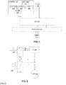
- the Figure 1 presents a system according to one embodiment of the invention.
- the system includes a variable speed drive 110, an electric motor 100 and a configuration device 120 according to one embodiment of the invention.
- the configuration device may be integrated into the variable speed drive 110 or may be separate from the variable speed drive 110.
- the variable speed drive 110 can be powered by a transformer 111 connected to a main electricity network 112, such as a network supplying a three-phase power supply.
- the electric motor 100 is of the three-phase type. However, no restriction is attached to the supply of the electric motor.
- the method can be implemented during a parameterization step (“commissioning”) before the normal operation of the engine in the context of its application.
- the method can be implemented once to identify the type of electric motor.
- the axes d and q form a reference in a plane perpendicular to an axis of rotation of the electric motor 100.
- the variable speed drive 110 comprises an inverter stage 202 which can be driven directly by motor voltages u a , u b and u c or by voltages motor on the d and q axes, via a transformation block 200.
- the transformation block 200 is configured to apply a change of frame, from the frame d,q to the frame a,b,c.
- This block receives as input the motor voltage u d on the d axis and the motor voltage u q on the q axis and determines, from the angle ⁇ s , the voltages u a , u b and u c to be applied on the three phases of the electric motor 100.
- Such a block 200 is well known and will not be detailed further in this description.
- the variable speed drive 110 further comprises means for measuring the motor currents i a , i b and i c , in particular current sensors intended to measure the currents i a , i b and i c present in the three phases of the motor M .
- the variable speed drive 110 can also comprise a second transformation block 201 to apply a change of reference, from the reference a,b,c to the reference d,q.
- This block receives as input the currents i a , i b and i c measured on the three phases of the electric motor and determines from the angle ⁇ s , the current i d on the axis d and the current i q on the q-axis.
- the unit for obtaining motor currents 121 of the configuration device 120 can be able to receive the motor currents measured by the variable speed drive 110 or can include its own means for measuring motor currents i a , i b and i c , in particular current sensors intended to measure the currents i a , i b and i c present in the three phases of the motor M.
- variable speed drive 110 Other configuration parameters are applicable to variable speed drive 110 according to the invention, such as alignment, fluxing, identification or compatibility parameters.
- the invention provides for configuring such parameters of the variable speed drive 110 according to the type of electric motor to which it is connected.
- the picture 3 is a diagram illustrating the steps of a method according to one embodiment of the invention.
- a maximum motor current value is acquired.
- a value can come from a manual entry by a user via a user interface of the configuration device (not represented on the figure 1 ).
- Such a step can be implemented prior to the other steps of the method according to the invention, in particular when the variable speed drive 110 is connected to the motor 100 or prior to its connection to the electric motor 100.
- Such a value is easily accessible by the user, in that it is generally indicated explicitly with the reference of the electric motor.
- a first motor voltage sequence S1 is transmitted to the variable speed drive 110 so as to control the power supply to the electric motor 100, by the motor voltage sequence injection unit 123.
- the motor voltages of the first sequence S1 can be the motor voltages u a , u b and u c or can be the motor voltages u d and u q .
- the motor voltages can in particular be transmitted to a control unit of the inverter stage 202.
- the first sequence S1 of motor voltages may comprise a ramp of increasing voltages on a slow time scale.
- the motor voltage values can be gradually increased until the motor current reaches the maximum current value obtained in step 300, which makes it possible to protect the electric motor by guaranteeing that the value of the motor current remains lower than the maximum value defined in step 300.
- the type of motor not being known, the variable speed drive 110 is not initially configured for the type of electric motor 100, and it is thus preferable to be careful not to damage the electric motor 100.
- measurements M1 of motor currents are obtained during the application of the sequence S1 of motor voltages.
- the measurements M1 can be obtained from a measurement means of the motor current obtaining unit 121, or can alternatively be received by the motor current obtaining unit 121 from means of measurement of the speed variator 110.
- a characteristic C1 of the electric motor is determined as a function of the measurements M1, by the motor type determination unit 124.
- the characteristic C1 can characterize the fact that the electric motor 100 has an anisotropic property or not. In practice, this is an anisotropy in the rotor of the electric motor 100.
- an asynchronous motor comprises a rotor in the form of a squirrel cage which is isotropic as a function of the directions of injection of the motor voltages, then that synchronous motors exhibit anisotropy and are thus sensitive to the direction of injection of motor voltages.
- step 303 may further include detecting a major axis of anisotropy.
- main is meant the axis along which the degree of anisotropy is greatest.
- Step 303 can also comprise the determination of a static gain of the motor (stator resistance), in particular, in the event of oscillations in the measurements M1, when the motor current value has stabilized after having oscillated.
- the anisotropy characteristic of the electric motor 110 can be determined according to whether or not oscillations are detected in the measurements M1 by the oscillation detection unit 122.
- the oscillations can be identified before the measurements of motor currents do not stabilize.
- the term “oscillation” can be understood to mean a succession of at least two measurement periods respectively above/below a stabilization value towards which the motor current converges.
- the first sequence S1 is applied twice, in two non-collinear directions D1 and D2.
- non-collinear directions means two vectors of values of motor voltages that are non-collinear with each other.
- the vectors include two components when the motor voltages u d and u q are used to control the variable speed drive 110, and include three components u a , u b and u c when the motor voltages are used to control the variable speed drive 110.
- the directions D1 and D2 form an angle substantially equal to 60 degrees.
- the two directions D1 and D2 are not orthogonal.
- the D2 direction includes a non-zero component along the q axis and a non-zero component along l axis d.
- Such an embodiment makes it possible to prevent the electric motor from being blocked in an unstable equilibrium position along the axis d, in particular when the electric motor is of the synchronous type with magnetic reluctance.
- measurements M11 of motor currents are obtained.
- the measurements M11 do not include oscillations (the motor current value stabilizes without oscillating)
- a second injection is carried out in a second direction non-collinear to the first direction and to the obtaining M12 measurements of motor currents. If, again, the measurements M12 do not include oscillations, it can be deduced that the electric motor 100 does not exhibit any anisotropy. Otherwise, the electric motor 100 exhibits anisotropy.
- the embodiment with two injections in non-collinear directions makes it possible to improve the detection of the characteristic C1 according to which the motor exhibits an anisotropy or not.
- an electric motor type can be determined based at least on the characteristic C1 determined in step 303, by the motor type determination unit 124. Other characteristics can be considered to determine the type of electric motor 100.
- the configuration unit 125 configures the variable speed drive 110 according to the type of electric motor 100. As indicated previously, such a configuration can comprise the definition of control laws or the setting of other configuration parameters .
- other characteristics of the electric motor 100 can be determined in order to allow the identification of other types of engine.
- the characteristic C1 characterizes the fact that the electric motor has an anisotropic property, it can be determined more precisely to what the anisotropy is due in order to precisely determine the type of the electric motor.
- the method according to one embodiment of the invention may further comprise an optional step of sending a command to the variable speed drive 110 in order to align the electric motor in the direction of the axis of anisotropy determined in step 303.
- the axis d is aligned with the anisotropy axis of the electric motor 100.
- the method can also comprise steps 307 to 309 making it possible to determine a second characteristic C2 of the electric motor 100.
- the characteristic C2 can characterize the fact that the electric motor 100 includes or does not include a permanent magnet.
- a second sequence S2 of motor voltages is transmitted to the variable speed drive 110 so as to control the power supply to the electric motor 100, by the motor voltage sequence injection unit 123.
- the second sequence S2 can be applied to drive the motor in rotation according to the axis of anisotropy.
- the first sequence S2 consists of applying motor voltages in a direction corresponding (or substantially equal) to a normal to the main axis of anisotropy determined in step 303.
- the sequence S2 can be predetermined.
- the sequence S2 can be recalculated according to the maximum motor current value of step 300 and according to the static gain determined at step 303, so as to ensure that the motor voltages applied in the sequence S2 n do not imply exceeding the maximum motor current value.
- step 308 which is performed in parallel with step 307, motor current measurements M2 are obtained during the application of the sequence S2 of motor voltages by the unit for obtaining this motor currents 121.
- the motor type determination unit 124 can determine the characteristic C2 that the electric motor 100 includes a permanent magnet or not. Once the main axis (magnet, reluctance) is identified, current combinations (i d ,i q ) make it possible to detect the presence of a voltage coming from the Back Electromotive Force B-EMF in English) which is generated by the rotating magnet. This voltage is proportional to the speed of rotation multiplied by the flux of the permanent magnet so its presence makes it possible to detect the presence of a permanent magnet.
- the sequence S2 can be applied in a direction orthogonal to an axis of salience d of the electric motor 100.
- the sequence S2 can also be determined so as to drive the electric motor 100 at a constant frequency.
- the motor current is then measured in the direction d of the motor anisotropy to obtain the measurements M2.
- the sequence S2 can then consist of gradually reducing the voltages applied to the electric motor by a predefined percentage (substantially equal to 20% for example), and the variation of the measurements M2 is analyzed. If the percentage of the variation of the motor current in the measurements M2 (absolute value of the difference between the initial value and the final value of the motor current along the axis d), compared to the absolute value of the initial value of the motor current along the axis d is less than a certain predefined threshold (substantially equal to 40% for example), then characteristic C2 may be that the electric motor does not include a permanent magnet. Otherwise, unit 124 can deduce that characteristic C2 is that electric motor 100 includes a permanent magnet.
- step 308 can consist in obtaining measurements M2 not of motor current but of motor voltages .
- Most speed variators 110 include such measuring means, in which case the configuration device may include an obtaining unit (not shown in the figure). figure 1 ) of the motor voltages connected to (capable of communicating with) the measuring means of the variable speed drive 110.
- the sequence S2 can be applied then the variable speed drive 110 is disconnected from the motor (the power part of the variable speed drive 110 more precisely) and the motor voltage measurements M2 are acquired during this “freewheeling” phase.
- unit 124 can determine that the electric motor includes a permanent magnet. In order to estimate the speed and the amplitude of the motor voltage, the unit 124 analyzes the measurements M2. If the ratio of the amplitude of the voltage to the motor speed does not vary or varies very little (the percentage of variation is less than a predetermined threshold), then the rotor of the electric motor presents a permanent flux, reflecting the existence of a permanent magnet (characteristic C2). Otherwise, the electric motor 100 does not include a permanent magnet.
- the characteristic C2 and the characteristic C1 can thus be taken into account during the step 304 of determining the type of the electric motor 100 implemented by the electric motor type determining unit 124.
- the method can also comprise steps 307 to 309 making it possible to determine a third characteristic C3 of the electric motor 100.
- the characteristic C3 can characterize the fact that the electric motor 100 has or does not have salience.
- the term “salience” is understood to mean the salience characteristic of the inductance of the electric motor: the electric flux, created by the electric current, circulates in the stator and the rotor. Depending on the geometric shape of the rotor, this electrical flow does not always pass through the same path depending on the position of the rotor due to the geometry of the latter, which is called geometric salience. Thus, in a rotor with salient poles, the inductances along the d and q axes are different because of this salience. On the other hand, in a rotor with a smooth pole, the inductances do not vary according to the position of the rotor.
- a third sequence S3 of motor voltages is transmitted to the variable speed drive 110 so as to control the power supply to the electric motor 100, by the motor voltage sequence injection unit 123.
- the sequence S3 is injected at least twice along at least two mutually orthogonal directions D3 and D4.
- respective measurements M31 and M32 of motor currents are acquired during step 311 (each of the measurements M31 to M32 is a series of one or more measurements).
- No restriction is attached to the sequence S3 of motor voltages, which may be a voltage step (in the case where the electric motor is equipped with a brake), or high-frequency motor voltages (in particular when the electric motor is not is not equipped with a brake).
- the sequence S3 can be injected along three directions D3, D4 and D5.
- D3, D4 and D5 can be separated by 120 degrees from each other.
- Directions D3, D4 and D5 correspond to the three motor phases (a, b, c) in the basic three-phase reference (located at 120 degrees from each other).
- the drive injects a very high frequency voltage directly on the three phases.
- the three-phase currents i a , i b and i c are used directly to detect the presence of salience.
- the measurements M31 and M32 are compared in order to deduce whether or not the electric motor 100 has salience. For example, if the measurements M31 and M32 are identical (or similar, i.e. their difference is less than a given threshold), then it can be deduced by the engine type determining unit 124 that the electric motor has no salience (characteristic C3). Conversely, if the measurements M31 and M32 are different (their difference is greater than the given threshold for example), it can be deduced by the motor type determination unit 124 that the electric motor has salience (characteristic C3) .
- the engine type determining unit 124 can determine the engine type by taking into account the characteristic C1 and the characteristic C3, or by taking into account the characteristics C1, C2 and C3.
- steps 310 to 312 can alternatively be carried out before steps 307 to 309.
- the figure 4 is a diagram illustrating the steps of a method according to a particular embodiment of the invention. It presents in particular the determination of the characteristics C1 to C3 in order to select a type of electric motor 100 from among four types of predefined electric motors, namely the induction motor, the surface permanent magnet motor (with smooth pole), the interior permanent magnet (with salient pole) and the reluctant synchronous motor.
- Step 400 is similar to step 300 of the picture 3 : A maximum motor current value is defined.
- a ramp S1 of motor voltages is applied and the motor current is measured at the same time (measurements M1).
- the motor current is measured and compared to the maximum motor current value. As long as the measured motor current is lower than the maximum motor current value, the S1 sequence is continued and the value of the applied motor voltage is increased.
- step 403 the oscillation detection unit 122 determines whether the measurements M1 have oscillations or not. If the oscillation detection unit 122 determines that the M1 measurements do not have oscillations at a step 404, then the motor type determination unit 124 determines that the motor is an induction type at a step 405 .
- the oscillation detection unit 122 determines that the measurements M1 exhibit oscillations at a step 406, it is deduced therefrom that the electric motor exhibits anisotropy and a main axis of anisotropy can be determined. by the engine type determination unit 124.
- variable speed drive 110 is then controlled at a step 407 by the motor voltage injection unit 123 so as to align the electric motor with the main axis of anisotropy.
- the motor voltage sequence S3 is then injected by the motor voltage injection unit 123 at a step 408, in at least two directions D3 and D4 orthogonal to each other.
- the motor current measurements M31 and M32 are obtained respectively for the directions D3 and D4.
- the motor type determination unit 124 determines, based on a comparison of the measurements M31 and M32, whether the electric motor 100 has salience or not at a step 409.
- the motor type determining unit 124 determines that the electric motor 100 is a surface permanent magnet synchronous type, at a step 410.
- the motor voltage injection unit 123 injects the sequence S2 of motor voltages at a step 411, and, in parallel, measurements M2 of motor currents (or of motor voltages according to the variant considered) are obtained.
- the motor type determining unit 124 determines whether the electric motor 100 has permanent magnetic flux or not at a step 412.
- the motor type determining unit 124 may determine that the electric motor 100 is an internal permanent magnet synchronous type, at a step 413.
- the motor type determining unit 124 determines that the electric motor 100 is of the synchronous reluctant type, at a step 414.
- the configuration unit 125 configures the variable speed drive 110 according to the type of electric motor determined.
- the figure 5 presents the structure of each of the units 122 to 125 of the configuration device 120 shown in the figure 1 .
- the unit comprises a processor 500 associated with a memory 501, such as a random access memory RAM, a read only memory, a flash memory, a hard disk and/or any type of memory.
- Memory 501 stores at least the data needed to perform unit operations. It can further store computer program instructions that can be executed by the processor 500 for the implementation of the functionalities of the unit. Alternatively, processor 500 can be replaced with a microcontroller designed and configured to perform the functionality of the unit.
- the unit further comprises two input and output interfaces 502 and 503. Alternatively, the unit comprises a single bidirectional input/output interface. Interfaces 502 and 503 allow communication with the other units of the configuration device and/or with the variable speed drive 110.
- Each of the units 122 to 125 can include the structure shown in the figure 5 .
- the functionalities of units 122 to 125 can be grouped together in the same structure with a processor executing all of these functionalities.
Landscapes
- Engineering & Computer Science (AREA)
- Power Engineering (AREA)
- Control Of Ac Motors In General (AREA)
- Control Of Electric Motors In General (AREA)
Claims (18)
- Verfahren für die Konfiguration eines Drehzahlreglers (110), der einen Elektromotor (100) speist, wobei das Verfahren die folgenden Vorgänge umfasst:- Anlegen (301) einer Motorspannungssequenz S1 an den Elektromotor über den Drehzahlregler;- Erhalten (302) von Motorstrommesswerten M1 während des Anliegens der Motorspannungssequenz S1;- Bestimmen (303) einer Eigenschaft C1 des Elektromotors auf Grundlage der Motorstrommesswerte M1;- Bestimmen (304) eines Elektromotortyps mindestens in Abhängigkeit von der Eigenschaft C1;- Konfigurieren (305) des Drehzahlreglers in Abhängigkeit vom bestimmten Elektromotortyp;wobei das Verfahren dadurch gekennzeichnet ist, dass die Spannungssequenz S1 zweimal nacheinander in mindestens zwei nicht kolinearen Spannungsrichtungen gemäß den folgenden Vorgängen angelegt wird:- Anlegen (301) der Motorspannungssequenz S1 an den Elektromotor in einer Richtung D1;- Erhalten (302) von Motorstrommesswerten M11 während des Anliegens der Spannungssequenz in der Richtung D1;- im Fall einer Feststellung, dass die Messwerte M11 Schwankungen aufweisen, Feststellen, dass der Elektromotor eine anisotrope Eigenschaft aufweist;- im gegenteiligen Fall:- Anlegen (301) der Motorspannungssequenz S1 an den Elektromotor ein zweites Mal mindestens in einer zur Richtung D1 nicht kolinearen Richtung D2;- Erhalten (302) der Motorstrommesswerte M12 während des Anliegens der Motorspannungssequenz S1 in die Richtung D2;- im Fall des Erkennens, dass die Messwerte M12 Schwankungen aufweisen, Feststellen (303), dass der Elektromotor eine anisotrope Eigenschaft aufweist;- im gegenteiligen Fall Feststellen (303), dass der Elektromotor keine anisotrope Eigenschaft aufweist.
- Verfahren nach Anspruch 1, wobei Anlegungen der Sequenzen S1 mindestens durch eine vorgegebene Verzögerung getrennt sind, wenn die Sequenz S1 ein zweites Mal angelegt wird.
- Verfahren nach einem der Ansprüche 1 und 2, wobei der Elektromotor, wenn der Elektromotor (100) keine anisotrope Eigenschaft aufweist, als vom Induktionstyp bestimmt wird.
- Verfahren nach einem der Ansprüche 1 bis 3, wobei das Verfahren, wenn der Elektromotor (100) eine anisotrope Eigenschaft aufweist, außerdem umfasst:- Erkennen (306) einer Anisotropiehauptachse des Elektromotors nach Anlegen der Motorspannungssequenz S1;- Anlegen (307) einer Motorspannungssequenz S2, um den Motor in Abhängigkeit von der Anisotropieachse in Drehung zu versetzen;- Erhalten (308) von Messwerten M2, die sich aus dem Anlegen der Motorspannungssequenz S2 ergeben;- Bestimmen (309) eines Anisotropietyps des Elektromotors in Abhängigkeit von den Messwerten M2;wobei der Elektromotortyp mindestens in Abhängigkeit von der Eigenschaft C1 und der Eigenschaft C2 bestimmt wird.
- Verfahren nach Anspruch 4, wobei die Messwerte M2 sind:- Motorstrommesswerte, die während des Anliegens der Sequenz S2 erfasst werden;- Motorspannungsmesswerte, die nach Anlegen der Sequenz S2 erfasst werden.
- Verfahren nach Anspruch 4 oder 5, wobei die Eigenschaft C2 die Tatsache kennzeichnet, dass der Elektromotor (100) einen Rotor umfasst, der einen permanenten Magnetfluss aufweist oder nicht.
- Verfahren nach Anspruch 6, wobei der Elektromotor, wenn der Elektromotor (100) keinen Permanentmagnet umfasst, als vom synchronen Reluktanztyp bestimmt wird.
- Verfahren nach einem der Ansprüche 5 bis 7, wobei die Motorspannungssequenz S2 in einer Richtung angelegt wird, die orthogonal zur Anisotropierichtung des Elektromotors (100) verläuft, um den Elektromotor in Drehung zu versetzen.
- Verfahren nach einem der Ansprüche 5 bis 8, das außerdem die Bestimmung einer statischen Verstärkung des Motors auf Grundlage der Messwerte M1 und der Sequenz S1 umfasst und wobei die Motorspannungssequenz S2 in Abhängigkeit von der bestimmten statischen Verstärkung bestimmt wird.
- Verfahren nach einem der Ansprüche 1 bis 9, wobei eine Motorspannungssequenz S3, wenn der Elektromotor (100) anisotrop ist, zweimal nacheinander in zwei orthogonale Spannungsrichtungen gemäß folgenden Vorgängen angelegt wird:- Anlegen (310) einer Motorspannungssequenz S3 an den Elektromotor in einer Richtung D3;- Erhalten (311) von Motorstrommesswerten M31 während des Anliegens der Motorspannungssequenz S3 in der Richtung D3;- Anlegen (310) einer Sequenz D3 von Motorspannungen an den Elektromotor in einer zur Richtung D3 nicht kolinearen Richtung D4;- Erhalten (311) von Motorstrommesswerten M32 während des Anliegens der Motorspannungssequenz S3 in der Richtung D4;- Vergleichen (312) der Messwerte M31 und M32, um eine Eigenschaft C3 des Elektromotors zu bestimmen;wobei der Elektromotortyp mindestens in Abhängigkeit von der Eigenschaft C1 und der Eigenschaft C3 bestimmt wird.
- Verfahren nach Anspruch 10, wobei die Eigenschaft C3 die Tatsache kennzeichnet, dass der Elektromotor (100) eine Salienz aufweist oder nicht, und wobei der Elektromotor, wenn der Elektromotor keine Induktionssalienz eines Rotors aufweist, als vom Typ mit oberflächlich angeordnetem Permanentmagnet bestimmt wird.
- Verfahren nach Anspruch 6 und Anspruch 11, wobei der Elektromotor, wenn der Elektromotor (100) eine Induktionssalienz des Rotors aufweist und der Motor einen Rotor umfasst, der einen permanenten Fluss umfasst, als vom Typ mit innerem Permanentmagnet bestimmt wird.
- Verfahren nach einem der Ansprüche 10 bis 12, wobei die Sequenz S3 eine hochfrequente Abfolge von Spannungen oder ein Spannungssprung ist.
- Verfahren nach einem der vorhergehenden Ansprüche, wobei die Motorspannungssequenz S1 darin besteht, die Motorspannung fortschreitend zu erhöhen, solange die Motorstrommesswerte M1 kleiner als ein Maximalwert des Motorstroms bleiben.
- Verfahren nach Anspruch 14, das einen vorbereitenden Schritt (300) der manuellen Erfassung des Maximalwertes des Motorstroms umfasst.
- Verfahren nach Anspruch 9 und nach Anspruch 14 oder 15, wobei die Spannungssequenz S2 in Abhängigkeit von der statischen Verstärkung und dem Maximalwert des Motorstroms bestimmt wird.
- Computerprogramm, das durch einen Prozessor (500) ausführbar ist und Anweisungen umfasst, um bei Ausführung durch den Prozessor die Schritte eines Verfahrens nach einem der Ansprüche 1 bis 16 umzusetzen.
- Vorrichtung für die Konfiguration eines Drehzahlreglers (110), der einen Elektromotor (100) speist, wobei die Vorrichtung für die Konfiguration umfasst:- eine Spannungseinspeiseeinheit (123), die dazu konfiguriert ist, eine Motorspannungssequenz S1 mittels eines Drehzahlreglers an den Elektromotor anzulegen;- eine Erhaltenseinheit (121), die dazu konfiguriert ist, Motorstrommesswerte M1 während des Anliegens der Spannungssequenz S1 zu erhalten;- eine Motortypbestimmungseinheit (124), die dazu konfiguriert ist, eine Eigenschaft C1 des Elektromotors auf Grundlage der Motorstrommesswerte M1 zu bestimmen und einen Elektromotortyp mindestens in Abhängigkeit von der Eigenschaft C1 zu bestimmen;- eine Konfigurationseinheit (125), die dazu konfiguriert ist, den Drehzahlregler in Abhängigkeit vom bestimmten Elektromotortyp zu konfigurieren,wobei die Vorrichtung dadurch gekennzeichnet ist, dass die Spannungseinspeiseeinheit (123) dazu konfiguriert ist, die Spannungssequenz S1 zweimal nacheinander in mindestens zwei nicht kolinearen Spannungsrichtungen anzulegen, und dass- die Spannungseinspeiseeinheit (123) dazu konfiguriert ist, die Motorspannungssequenz S1 in einer Richtung D1 an den Elektromotor anzulegen;- die Erhaltenseinheit (121) dazu konfiguriert ist, Motorstrommesswerte M11 während des Anliegens der Spannungssequenz in der Richtung D1 zu erhalten (302);- im Falle einer Feststellung, dass die Messwerte M11 Schwankungen aufweisen, die Motortypbestimmungseinheit (124) dazu konfiguriert ist, festzustellen, dass der Elektromotor eine anisotrope Eigenschaft aufweist,- im gegenteiligen Fall:- die Spannungseinspeiseeinheit (123) dazu konfiguriert ist, die Motorspannungssequenz S1 ein zweites Mal mindestens in einer zur Richtung D1 nicht kolinearen Richtung D2 anzulegen;- die Erhaltenseinheit (121) dazu konfiguriert ist, Motorstrommesswerte M12 während des Anliegens der Motorspannungssequenz S1 in der Richtung D2 zu erhalten;- im Falle einer Feststellung, dass die Messwerte M12 Schwankungen aufweisen, die Motortypbestimmungseinheit (124) dazu konfiguriert ist, festzustellen, dass der Elektromotor eine anisotrope Eigenschaft aufweist,- im gegenteiligen Fall die Motortypbestimmungseinheit (124) dazu konfiguriert ist, festzustellen, dass der Elektromotor keine anisotrope Eigenschaft aufweist.
Applications Claiming Priority (1)
| Application Number | Priority Date | Filing Date | Title |
|---|---|---|---|
| FR1902610A FR3093813A1 (fr) | 2019-03-14 | 2019-03-14 | Détection du type d’un moteur électrique pour configuration d’un variateur de vitesse |
Publications (2)
| Publication Number | Publication Date |
|---|---|
| EP3709504A1 EP3709504A1 (de) | 2020-09-16 |
| EP3709504B1 true EP3709504B1 (de) | 2022-06-01 |
Family
ID=67441360
Family Applications (1)
| Application Number | Title | Priority Date | Filing Date |
|---|---|---|---|
| EP20159271.4A Active EP3709504B1 (de) | 2019-03-14 | 2020-02-25 | Verfahren, programm und vorrichtung für die konfiguration eines drehzahlreglers speisend eines elektromotors |
Country Status (5)
| Country | Link |
|---|---|
| US (1) | US11095236B2 (de) |
| EP (1) | EP3709504B1 (de) |
| CN (1) | CN111697888B (de) |
| ES (1) | ES2920161T3 (de) |
| FR (1) | FR3093813A1 (de) |
Families Citing this family (1)
| Publication number | Priority date | Publication date | Assignee | Title |
|---|---|---|---|---|
| CN112230144B (zh) * | 2020-09-30 | 2024-06-28 | 杭州士兰微电子股份有限公司 | 电机类型的识别方法及装置 |
Citations (1)
| Publication number | Priority date | Publication date | Assignee | Title |
|---|---|---|---|---|
| EP1257049B1 (de) * | 2001-05-09 | 2006-12-27 | Hitachi, Ltd. | Regelvorrichtung für eine Wechselstromquelle |
Family Cites Families (7)
| Publication number | Priority date | Publication date | Assignee | Title |
|---|---|---|---|---|
| US4012652A (en) * | 1973-04-26 | 1977-03-15 | Electrical Remote Control Company, Ltd. | Unidirectional self-starting electrical motors with shaded poles and shaded magnetic shunt |
| US7557528B2 (en) * | 2006-09-25 | 2009-07-07 | General Electric Company | System, method, and computer software code for detection and interchangeability of a motor |
| CN101303393B (zh) * | 2007-05-08 | 2011-01-05 | 鸿富锦精密工业(深圳)有限公司 | 马达运行的监控系统及其监控方法 |
| FR2933550B1 (fr) * | 2008-07-01 | 2012-10-12 | Schneider Toshiba Inverter Europe Sas | Procede de determination des inductances d'une machine synchrone a aimants permanents |
| FR2977997B1 (fr) * | 2011-07-12 | 2013-07-12 | Schneider Toshiba Inverter | Procede de commande mis en oeuvre dans un variateur de vitesse pour controler la deceleration d'un moteur electrique en cas de coupure d'alimentation |
| US8947034B2 (en) * | 2013-03-14 | 2015-02-03 | Regal Beloit America, Inc. | Methods and systems for controlling an electric motor |
| DE102015110174A1 (de) * | 2015-06-24 | 2016-12-29 | Carl Zeiss Industrielle Messtechnik Gmbh | Verfahren und Vorrichtung zum Prüfen einer elektrischen Größe einer elektrischen Maschine |
-
2019
- 2019-03-14 FR FR1902610A patent/FR3093813A1/fr not_active Withdrawn
-
2020
- 2020-02-20 US US16/796,333 patent/US11095236B2/en active Active
- 2020-02-25 ES ES20159271T patent/ES2920161T3/es active Active
- 2020-02-25 EP EP20159271.4A patent/EP3709504B1/de active Active
- 2020-03-16 CN CN202010180416.1A patent/CN111697888B/zh active Active
Patent Citations (1)
| Publication number | Priority date | Publication date | Assignee | Title |
|---|---|---|---|---|
| EP1257049B1 (de) * | 2001-05-09 | 2006-12-27 | Hitachi, Ltd. | Regelvorrichtung für eine Wechselstromquelle |
Also Published As
| Publication number | Publication date |
|---|---|
| US11095236B2 (en) | 2021-08-17 |
| US20200295679A1 (en) | 2020-09-17 |
| EP3709504A1 (de) | 2020-09-16 |
| FR3093813A1 (fr) | 2020-09-18 |
| CN111697888B (zh) | 2025-12-12 |
| ES2920161T3 (es) | 2022-08-01 |
| CN111697888A (zh) | 2020-09-22 |
Similar Documents
| Publication | Publication Date | Title |
|---|---|---|
| EP2684289B1 (de) | In einem stromwandler implementiertes steuerverfahren zur identifizierung von parametern in bezug auf die magnetische sättigung eines elektromotors | |
| EP2246973B1 (de) | Verfahren zur Positionsbestimmung des Flussvektors eines Motors | |
| EP2003461B1 (de) | Verfahren zum Feststellen eines Ausfalls einer oder mehrerer Phasen bei einem Dauermagnet-Synchronmotor | |
| EP1881594A1 (de) | Verfahren zur Justierung der Parameter eines Synchronmotors und Verwendung eines solchen Verfahrens in einer Drehzahlregelung | |
| FR2975845A1 (fr) | Suivi de rotor de machine synchrone a inducteur bobine utilisant un signal sans capteur d'injection de porteuse et un courant d'excitation | |
| EP3092711B1 (de) | Verfahren um die polarität eines rotors einer drehenden elektrischen maschine zu bestimmen | |
| EP3451525B1 (de) | Verfahren zur identifizierung der magnetischen sättigungsparameter eines asynchronen elektromotors | |
| EP1398869B1 (de) | Prozess und Rechner zur Bestimmung des Drehwinkels eines Rotors in Ruhelage, Steuereinheit und System unter Verwendung des Rechners | |
| EP3709504B1 (de) | Verfahren, programm und vorrichtung für die konfiguration eines drehzahlreglers speisend eines elektromotors | |
| EP3166220B1 (de) | Vorrichtung zur dynamischen begrenzung, und verfahren zur dynamischen begrenzung durch eine solche vorrichtung | |
| EP2963802B1 (de) | Steuerungsverfahren zum anlassen eines elektrischen synchronmotors | |
| EP3284168B1 (de) | Verfahren zur steuerung des drehmoments einer elektrischen synchronmaschine | |
| EP3462603B1 (de) | Steuerungsverfahren zur überprüfung der kompatibilität zwischen einem drehzahlregler und dem eingangsfilter | |
| FR3044185A1 (fr) | Procede de commande d'une machine synchrone a aimants permanents, et dispositif correspondant | |
| EP3322084A1 (de) | Anlasskontrollverfahren eines dreiphasigen kollektorlosen elektrischen synchronmotors | |
| EP3503380B1 (de) | Steuerverfahren eines elektromotors, das eine identifizierungssequenz eines transformators umfasst | |
| EP3404822B1 (de) | Anlassereinheit eines motors, und anlassverfahren | |
| EP3128667B1 (de) | Steuerungsverfahren zum anlassen eines elektrischen synchronmotors | |
| WO2021198594A2 (fr) | Procédé de commande d'un redresseur connecté à une génératrice électrique synchrone à aimants permanents pour fournir une tension continue, programme d'ordinateur et dispositif correspondant | |
| WO2021048388A1 (fr) | Procédé de contrôle en vitesse de moteurs sans balai | |
| FR3030938A1 (fr) | Machine a reluctance synchrone sinus. |
Legal Events
| Date | Code | Title | Description |
|---|---|---|---|
| PUAI | Public reference made under article 153(3) epc to a published international application that has entered the european phase |
Free format text: ORIGINAL CODE: 0009012 |
|
| STAA | Information on the status of an ep patent application or granted ep patent |
Free format text: STATUS: THE APPLICATION HAS BEEN PUBLISHED |
|
| AK | Designated contracting states |
Kind code of ref document: A1 Designated state(s): AL AT BE BG CH CY CZ DE DK EE ES FI FR GB GR HR HU IE IS IT LI LT LU LV MC MK MT NL NO PL PT RO RS SE SI SK SM TR |
|
| AX | Request for extension of the european patent |
Extension state: BA ME |
|
| STAA | Information on the status of an ep patent application or granted ep patent |
Free format text: STATUS: REQUEST FOR EXAMINATION WAS MADE |
|
| 17P | Request for examination filed |
Effective date: 20210305 |
|
| RBV | Designated contracting states (corrected) |
Designated state(s): AL AT BE BG CH CY CZ DE DK EE ES FI FR GB GR HR HU IE IS IT LI LT LU LV MC MK MT NL NO PL PT RO RS SE SI SK SM TR |
|
| GRAP | Despatch of communication of intention to grant a patent |
Free format text: ORIGINAL CODE: EPIDOSNIGR1 |
|
| STAA | Information on the status of an ep patent application or granted ep patent |
Free format text: STATUS: GRANT OF PATENT IS INTENDED |
|
| INTG | Intention to grant announced |
Effective date: 20220323 |
|
| GRAS | Grant fee paid |
Free format text: ORIGINAL CODE: EPIDOSNIGR3 |
|
| GRAA | (expected) grant |
Free format text: ORIGINAL CODE: 0009210 |
|
| STAA | Information on the status of an ep patent application or granted ep patent |
Free format text: STATUS: THE PATENT HAS BEEN GRANTED |
|
| AK | Designated contracting states |
Kind code of ref document: B1 Designated state(s): AL AT BE BG CH CY CZ DE DK EE ES FI FR GB GR HR HU IE IS IT LI LT LU LV MC MK MT NL NO PL PT RO RS SE SI SK SM TR |
|
| REG | Reference to a national code |
Ref country code: GB Ref legal event code: FG4D Free format text: NOT ENGLISH |
|
| REG | Reference to a national code |
Ref country code: AT Ref legal event code: REF Ref document number: 1496092 Country of ref document: AT Kind code of ref document: T Effective date: 20220615 Ref country code: CH Ref legal event code: EP |
|
| REG | Reference to a national code |
Ref country code: IE Ref legal event code: FG4D Free format text: LANGUAGE OF EP DOCUMENT: FRENCH |
|
| REG | Reference to a national code |
Ref country code: DE Ref legal event code: R096 Ref document number: 602020003309 Country of ref document: DE |
|
| REG | Reference to a national code |
Ref country code: ES Ref legal event code: FG2A Ref document number: 2920161 Country of ref document: ES Kind code of ref document: T3 Effective date: 20220801 |
|
| REG | Reference to a national code |
Ref country code: LT Ref legal event code: MG9D |
|
| REG | Reference to a national code |
Ref country code: NL Ref legal event code: MP Effective date: 20220601 |
|
| PG25 | Lapsed in a contracting state [announced via postgrant information from national office to epo] |
Ref country code: SE Free format text: LAPSE BECAUSE OF FAILURE TO SUBMIT A TRANSLATION OF THE DESCRIPTION OR TO PAY THE FEE WITHIN THE PRESCRIBED TIME-LIMIT Effective date: 20220601 Ref country code: NO Free format text: LAPSE BECAUSE OF FAILURE TO SUBMIT A TRANSLATION OF THE DESCRIPTION OR TO PAY THE FEE WITHIN THE PRESCRIBED TIME-LIMIT Effective date: 20220901 Ref country code: LT Free format text: LAPSE BECAUSE OF FAILURE TO SUBMIT A TRANSLATION OF THE DESCRIPTION OR TO PAY THE FEE WITHIN THE PRESCRIBED TIME-LIMIT Effective date: 20220601 Ref country code: HR Free format text: LAPSE BECAUSE OF FAILURE TO SUBMIT A TRANSLATION OF THE DESCRIPTION OR TO PAY THE FEE WITHIN THE PRESCRIBED TIME-LIMIT Effective date: 20220601 Ref country code: GR Free format text: LAPSE BECAUSE OF FAILURE TO SUBMIT A TRANSLATION OF THE DESCRIPTION OR TO PAY THE FEE WITHIN THE PRESCRIBED TIME-LIMIT Effective date: 20220902 Ref country code: FI Free format text: LAPSE BECAUSE OF FAILURE TO SUBMIT A TRANSLATION OF THE DESCRIPTION OR TO PAY THE FEE WITHIN THE PRESCRIBED TIME-LIMIT Effective date: 20220601 Ref country code: BG Free format text: LAPSE BECAUSE OF FAILURE TO SUBMIT A TRANSLATION OF THE DESCRIPTION OR TO PAY THE FEE WITHIN THE PRESCRIBED TIME-LIMIT Effective date: 20220901 |
|
| REG | Reference to a national code |
Ref country code: AT Ref legal event code: MK05 Ref document number: 1496092 Country of ref document: AT Kind code of ref document: T Effective date: 20220601 |
|
| PG25 | Lapsed in a contracting state [announced via postgrant information from national office to epo] |
Ref country code: RS Free format text: LAPSE BECAUSE OF FAILURE TO SUBMIT A TRANSLATION OF THE DESCRIPTION OR TO PAY THE FEE WITHIN THE PRESCRIBED TIME-LIMIT Effective date: 20220601 Ref country code: PL Free format text: LAPSE BECAUSE OF FAILURE TO SUBMIT A TRANSLATION OF THE DESCRIPTION OR TO PAY THE FEE WITHIN THE PRESCRIBED TIME-LIMIT Effective date: 20220601 Ref country code: LV Free format text: LAPSE BECAUSE OF FAILURE TO SUBMIT A TRANSLATION OF THE DESCRIPTION OR TO PAY THE FEE WITHIN THE PRESCRIBED TIME-LIMIT Effective date: 20220601 |
|
| PG25 | Lapsed in a contracting state [announced via postgrant information from national office to epo] |
Ref country code: NL Free format text: LAPSE BECAUSE OF FAILURE TO SUBMIT A TRANSLATION OF THE DESCRIPTION OR TO PAY THE FEE WITHIN THE PRESCRIBED TIME-LIMIT Effective date: 20220601 |
|
| PG25 | Lapsed in a contracting state [announced via postgrant information from national office to epo] |
Ref country code: SM Free format text: LAPSE BECAUSE OF FAILURE TO SUBMIT A TRANSLATION OF THE DESCRIPTION OR TO PAY THE FEE WITHIN THE PRESCRIBED TIME-LIMIT Effective date: 20220601 Ref country code: SK Free format text: LAPSE BECAUSE OF FAILURE TO SUBMIT A TRANSLATION OF THE DESCRIPTION OR TO PAY THE FEE WITHIN THE PRESCRIBED TIME-LIMIT Effective date: 20220601 Ref country code: RO Free format text: LAPSE BECAUSE OF FAILURE TO SUBMIT A TRANSLATION OF THE DESCRIPTION OR TO PAY THE FEE WITHIN THE PRESCRIBED TIME-LIMIT Effective date: 20220601 Ref country code: PT Free format text: LAPSE BECAUSE OF FAILURE TO SUBMIT A TRANSLATION OF THE DESCRIPTION OR TO PAY THE FEE WITHIN THE PRESCRIBED TIME-LIMIT Effective date: 20221003 Ref country code: EE Free format text: LAPSE BECAUSE OF FAILURE TO SUBMIT A TRANSLATION OF THE DESCRIPTION OR TO PAY THE FEE WITHIN THE PRESCRIBED TIME-LIMIT Effective date: 20220601 Ref country code: CZ Free format text: LAPSE BECAUSE OF FAILURE TO SUBMIT A TRANSLATION OF THE DESCRIPTION OR TO PAY THE FEE WITHIN THE PRESCRIBED TIME-LIMIT Effective date: 20220601 Ref country code: AT Free format text: LAPSE BECAUSE OF FAILURE TO SUBMIT A TRANSLATION OF THE DESCRIPTION OR TO PAY THE FEE WITHIN THE PRESCRIBED TIME-LIMIT Effective date: 20220601 |
|
| PG25 | Lapsed in a contracting state [announced via postgrant information from national office to epo] |
Ref country code: IS Free format text: LAPSE BECAUSE OF FAILURE TO SUBMIT A TRANSLATION OF THE DESCRIPTION OR TO PAY THE FEE WITHIN THE PRESCRIBED TIME-LIMIT Effective date: 20221001 |
|
| REG | Reference to a national code |
Ref country code: DE Ref legal event code: R097 Ref document number: 602020003309 Country of ref document: DE |
|
| PG25 | Lapsed in a contracting state [announced via postgrant information from national office to epo] |
Ref country code: AL Free format text: LAPSE BECAUSE OF FAILURE TO SUBMIT A TRANSLATION OF THE DESCRIPTION OR TO PAY THE FEE WITHIN THE PRESCRIBED TIME-LIMIT Effective date: 20220601 |
|
| PLBE | No opposition filed within time limit |
Free format text: ORIGINAL CODE: 0009261 |
|
| STAA | Information on the status of an ep patent application or granted ep patent |
Free format text: STATUS: NO OPPOSITION FILED WITHIN TIME LIMIT |
|
| PG25 | Lapsed in a contracting state [announced via postgrant information from national office to epo] |
Ref country code: DK Free format text: LAPSE BECAUSE OF FAILURE TO SUBMIT A TRANSLATION OF THE DESCRIPTION OR TO PAY THE FEE WITHIN THE PRESCRIBED TIME-LIMIT Effective date: 20220601 |
|
| 26N | No opposition filed |
Effective date: 20230302 |
|
| PG25 | Lapsed in a contracting state [announced via postgrant information from national office to epo] |
Ref country code: SI Free format text: LAPSE BECAUSE OF FAILURE TO SUBMIT A TRANSLATION OF THE DESCRIPTION OR TO PAY THE FEE WITHIN THE PRESCRIBED TIME-LIMIT Effective date: 20220601 |
|
| PG25 | Lapsed in a contracting state [announced via postgrant information from national office to epo] |
Ref country code: MC Free format text: LAPSE BECAUSE OF FAILURE TO SUBMIT A TRANSLATION OF THE DESCRIPTION OR TO PAY THE FEE WITHIN THE PRESCRIBED TIME-LIMIT Effective date: 20220601 |
|
| REG | Reference to a national code |
Ref country code: CH Ref legal event code: PL |
|
| REG | Reference to a national code |
Ref country code: BE Ref legal event code: MM Effective date: 20230228 |
|
| PG25 | Lapsed in a contracting state [announced via postgrant information from national office to epo] |
Ref country code: LU Free format text: LAPSE BECAUSE OF NON-PAYMENT OF DUE FEES Effective date: 20230225 Ref country code: LI Free format text: LAPSE BECAUSE OF NON-PAYMENT OF DUE FEES Effective date: 20230228 Ref country code: CH Free format text: LAPSE BECAUSE OF NON-PAYMENT OF DUE FEES Effective date: 20230228 |
|
| REG | Reference to a national code |
Ref country code: IE Ref legal event code: MM4A |
|
| PG25 | Lapsed in a contracting state [announced via postgrant information from national office to epo] |
Ref country code: IE Free format text: LAPSE BECAUSE OF NON-PAYMENT OF DUE FEES Effective date: 20230225 |
|
| PG25 | Lapsed in a contracting state [announced via postgrant information from national office to epo] |
Ref country code: BE Free format text: LAPSE BECAUSE OF NON-PAYMENT OF DUE FEES Effective date: 20230228 |
|
| PG25 | Lapsed in a contracting state [announced via postgrant information from national office to epo] |
Ref country code: BG Free format text: LAPSE BECAUSE OF FAILURE TO SUBMIT A TRANSLATION OF THE DESCRIPTION OR TO PAY THE FEE WITHIN THE PRESCRIBED TIME-LIMIT Effective date: 20220601 |
|
| PG25 | Lapsed in a contracting state [announced via postgrant information from national office to epo] |
Ref country code: BG Free format text: LAPSE BECAUSE OF FAILURE TO SUBMIT A TRANSLATION OF THE DESCRIPTION OR TO PAY THE FEE WITHIN THE PRESCRIBED TIME-LIMIT Effective date: 20220601 |
|
| PGFP | Annual fee paid to national office [announced via postgrant information from national office to epo] |
Ref country code: DE Payment date: 20250226 Year of fee payment: 6 |
|
| PGFP | Annual fee paid to national office [announced via postgrant information from national office to epo] |
Ref country code: ES Payment date: 20250312 Year of fee payment: 6 |
|
| PGFP | Annual fee paid to national office [announced via postgrant information from national office to epo] |
Ref country code: FR Payment date: 20250224 Year of fee payment: 6 |
|
| PGFP | Annual fee paid to national office [announced via postgrant information from national office to epo] |
Ref country code: IT Payment date: 20250225 Year of fee payment: 6 Ref country code: GB Payment date: 20250218 Year of fee payment: 6 |
|
| PG25 | Lapsed in a contracting state [announced via postgrant information from national office to epo] |
Ref country code: CY Free format text: LAPSE BECAUSE OF FAILURE TO SUBMIT A TRANSLATION OF THE DESCRIPTION OR TO PAY THE FEE WITHIN THE PRESCRIBED TIME-LIMIT; INVALID AB INITIO Effective date: 20200225 |
|
| PG25 | Lapsed in a contracting state [announced via postgrant information from national office to epo] |
Ref country code: HU Free format text: LAPSE BECAUSE OF FAILURE TO SUBMIT A TRANSLATION OF THE DESCRIPTION OR TO PAY THE FEE WITHIN THE PRESCRIBED TIME-LIMIT; INVALID AB INITIO Effective date: 20200225 |
|
| PG25 | Lapsed in a contracting state [announced via postgrant information from national office to epo] |
Ref country code: TR Free format text: LAPSE BECAUSE OF FAILURE TO SUBMIT A TRANSLATION OF THE DESCRIPTION OR TO PAY THE FEE WITHIN THE PRESCRIBED TIME-LIMIT Effective date: 20220601 |