EP2246973B1 - Verfahren zur Positionsbestimmung des Flussvektors eines Motors - Google Patents
Verfahren zur Positionsbestimmung des Flussvektors eines Motors Download PDFInfo
- Publication number
- EP2246973B1 EP2246973B1 EP10159258.2A EP10159258A EP2246973B1 EP 2246973 B1 EP2246973 B1 EP 2246973B1 EP 10159258 A EP10159258 A EP 10159258A EP 2246973 B1 EP2246973 B1 EP 2246973B1
- Authority
- EP
- European Patent Office
- Prior art keywords
- frequency
- reference frame
- injection
- rotor
- stator
- Prior art date
- Legal status (The legal status is an assumption and is not a legal conclusion. Google has not performed a legal analysis and makes no representation as to the accuracy of the status listed.)
- Active
Links
Images


Classifications
-
- H—ELECTRICITY
- H02—GENERATION; CONVERSION OR DISTRIBUTION OF ELECTRIC POWER
- H02P—CONTROL OR REGULATION OF ELECTRIC MOTORS, ELECTRIC GENERATORS OR DYNAMO-ELECTRIC CONVERTERS; CONTROLLING TRANSFORMERS, REACTORS OR CHOKE COILS
- H02P21/00—Arrangements or methods for the control of electric machines by vector control, e.g. by control of field orientation
- H02P21/24—Vector control not involving the use of rotor position or rotor speed sensors
- H02P21/32—Determining the initial rotor position
-
- H—ELECTRICITY
- H02—GENERATION; CONVERSION OR DISTRIBUTION OF ELECTRIC POWER
- H02P—CONTROL OR REGULATION OF ELECTRIC MOTORS, ELECTRIC GENERATORS OR DYNAMO-ELECTRIC CONVERTERS; CONTROLLING TRANSFORMERS, REACTORS OR CHOKE COILS
- H02P21/00—Arrangements or methods for the control of electric machines by vector control, e.g. by control of field orientation
- H02P21/14—Estimation or adaptation of machine parameters, e.g. flux, current or voltage
- H02P21/18—Estimation of position or speed
-
- H—ELECTRICITY
- H02—GENERATION; CONVERSION OR DISTRIBUTION OF ELECTRIC POWER
- H02P—CONTROL OR REGULATION OF ELECTRIC MOTORS, ELECTRIC GENERATORS OR DYNAMO-ELECTRIC CONVERTERS; CONTROLLING TRANSFORMERS, REACTORS OR CHOKE COILS
- H02P2203/00—Indexing scheme relating to controlling arrangements characterised by the means for detecting the position of the rotor
- H02P2203/11—Determination or estimation of the rotor position or other motor parameters based on the analysis of high-frequency signals
Definitions
- the present invention relates to a method for determining the position of a flow vector of an electric motor, which is controlled by a variable speed drive and is intended to drive a load.
- the method is performed without a sensorless or sensorless sensor, and is based on detecting an error in the estimated position of the flux vector using a low frequency current injection.
- the drive control system requires information on the position of the motor flow vector (usually the rotor).
- This position of the rotor flux vector can be satisfactorily estimated in a closed loop using a rotor position or speed sensor, such as an encoder. Nevertheless, such a sensor is relatively expensive and is mechanically and electrically sensitive, which can lead to difficulties in development.
- the position of the flux vector is estimated from a modeling of the motor and the stator voltage of the motor.
- This approach is effective when the main frequency of the stator voltage, which is the image of the speed reference applied to the motor, is sufficiently high that the flux-induced internal electromotive force (emf) can be reliably detected.
- emf flux-induced internal electromotive force
- auxiliary signal To provide reliable detection of the position of the low speed rotor flux vector without the use of a sensor, various methods based on the injection of an auxiliary signal may be employed.
- the injection of a voltage or current into the stator windings at a frequency different from the main frequency is used to determine the position information of the rotor flux vector by observing and analyzing the response of the rotor. current or voltage of the stator.
- One method is called low frequency harmonic current injection.
- the purpose of this method is to generate small oscillations of torque and rotor speed capable of inducing detectable voltage oscillations.
- the term low frequency in this context means that the injection frequency (or harmonic frequency) is within the mechanical bandwidth of the mechanical drive system. For example, for motors of nominal frequency equal to about 50Hz-60Hz, the typical injection frequency would be of the order of 25Hz-50Hz.
- the low frequency current injection method is already used for induction motor control, see in particular: V.-M. Leppanen, J. Luomi, 'Speed-Sensorless Induction Machine Control for Zero Speed and Frequency', IEEE Transactions on Industrial Electronics, Vol. 51, No. 5, Oct. 2004, pp. 1041-1047 .
- This method is also used for PMSM synchronous motor control, see in particular: Wu, Y. Li, X. Miao, IEEE Power Electronics Specialists Conference, PESC 2007, June 2007 pp. 568 - 573 .
- This method makes it possible to determine the components of the stator voltage which are induced by the rotor flux following the controlled injection of current, so as to subsequently detect the position of the rotor flux vector.
- one approach is to use a usual PI regulator (Proportional Integral) which is synchronous with the reference reference (SRF - Synchronous Reference Frame) of the main motor current, also noted as a reference (d, q), and which has a sufficient bandwidth (ie capable of also regulating the injected current), then using an equation of the stator voltage to determine the induced internal electromotive force.
- PI regulator Proportional Integral
- the document EP1944860 discloses a method for sensorless estimation of the speed and position of a permanent magnet synchronous machine.
- a high frequency signal is injected including a direct component and a quadrature component.
- the direct component has a first frequency and the quadrature component has a second frequency, the first and second frequencies being different.
- the object of the invention is therefore to remedy these difficulties by proposing a method for determining the position of the rotor flux vector which is simple, precise and reliable, in particular when the engine is running at a reduced speed and even at zero speed.
- the method does not use a position sensor and applies to both synchronous motors and induction motors (such as asynchronous motors). It allows in particular an alignment of the control system with the initial position of the rotor of a synchronous motor and does not require a particular engine design, such as the existence of projections (saliency) in a synchronous motor.
- the invention describes a method for determining the position of a rotor flux vector of an electric motor having a stator and a rotor.
- the method comprises (i) a step of injecting a first current vector into a first injection mark rotating at a first frequency relative to a reference reference synchronous with the rotation of the engine, and a second current vector in a second injection mark rotating at a second frequency relative to the reference mark, the second frequency being the opposite of the first frequency, (ii) a step of determining a first stator flux induced output voltage a first synchronous integrator module with the first injection mark and a second stator flux induced voltage outputted from a second synchronous integrator module with the second injection mark, (iii) a control step of the position of the rotor flux vector by minimizing the error between a real position of the rotor flux vector and an estimated position of the rotor flux vector, the error being completed from the second stator flux induced voltage.
- the error is determined from the first stator flux induced voltage and the second stator flux induced voltage.
- the amplitude of the second current vector is equal to zero.
- the amplitude of the second current vector is equal to the amplitude of the first current vector.
- the method also comprises a step of injecting a third current vector into a third injection mark rotating at a third frequency relative to the reference mark, and a fourth current vector into a fourth mark injection circuit rotating at a fourth frequency relative to the reference mark, the fourth frequency being the opposite of the third frequency and the third frequency being twice the first frequency.
- the invention also relates to a variable speed drive for driving a synchronous or asynchronous electric motor.
- the drive comprises an inverter module and a control module which is intended to control the inverter module and which comprises a first integrator module and a second integrator module, so as to implement such a determination method.
- a variable speed drive is usually responsible for driving an electric motor M, which comprises a stator and a rotor, by delivering a variable frequency alternating voltage to the stator windings (PWM - Pulse Width Modulation).
- the object of the invention is to simply determine the position of the rotor flux vector, without using a speed or position sensor. The position of the rotor flux vector will make it possible to know the position and / or the speed of the rotor of the engine, thus making it possible to optimize the control of the engine.
- the determination method is implemented in the variable speed drive.
- the electric motor can be an engine synchronous (for example a permanent magnet motor - PMSM) or an asynchronous motor (induction motor) and may or may not include projections.
- a variable speed drive for controlling a motor M comprises an inverter module 20 for transforming a DC voltage 21 into three-phase voltages 22 applied to the different windings of the stator of the motor.
- the variator comprises a control module 10 which must control the semiconductor components of the inverter module 20 from a voltage which is composed of three components U a , U b , U c in a fixed three-phase reference frame. , b, c.
- the control module 10 delivers a control voltage which is composed of two components U d , U q in a reference frame which is synchronous with the speed of rotation of the motor.
- This reference mark is an orthogonal mark which is usually called a mark d, q - the axis d representing the axis of rotor flux and the axis q representing the axis of engine torque.
- the components U d , U q in the synchronous reference frame d, q are transformed by a converter block 23 d, q -> a, b, c to give the components U a , U b , U c in the three-phase reference fixed a, b, c for controlling the inverter module 20.
- the reference mark d, q makes an angle called ⁇ s relative to a fixed reference, the angle ⁇ s being determined from the estimated stator speed ⁇ s .
- the angle ⁇ s corresponds to the estimated position of the rotor flux vector.
- ⁇ the error, called ⁇ , of the angular position of the rotor flux vector, so as to align the rotor flux with the axis d of the reference reference d, q.
- This error ⁇ corresponds to the difference between the actual position ⁇ R of the rotor flux vector and the estimated position ⁇ S of the rotor flux vector.
- the control module 10 receives measured currents I sd , I sq in the reference reference d, q. These measured currents I sd , I sq come, after transformation by a converter block 24 a, b, c -> d, q, measurements of currents flowing in the stator windings according to the fixed three-phase reference a, b, c and called I sa , I sb , I sc . In known manner, at least two of the three stator current measurements I sa, sb I, I sc are necessary for the converter unit 24 to obtain the measured currents I sd, I sq in the reference frame d, q. To carry out the transformations between the fixed reference mark a, b, c and the mark d, q, the converter blocks 23, 24 use the angle ⁇ s .
- the control module 10 also receives as input a reference main current I ref comprising two components I dref , I qref in the reference frame d, q.
- the current I dref of axis d corresponds to the main current of flow and the current I qref of axis q corresponds to the main current of torque.
- the reference main current I ref makes it possible to turn the motor M with the desired speed and torque. It is determined in particular so as to minimize the difference between a motor speed reference ⁇ ref desired and an estimated speed ⁇ r of rotation of the rotor obtained from the stator speed ⁇ s .
- the method described in the invention provides for injecting an injection current I h , having components I dh and I qh in the reference reference d, q, in superposition of the main currents I dref , I qref .
- the method provides for injecting a first current vector according to a first injection mark x + , y + , this first reference x + , y + rotating at a first injection frequency ⁇ with respect to the reference reference d , q synchronous with the rotation of the motor.
- the method also provides for injecting a second current vector into a second injection mark x - , y - rotating at a second injection frequency - ⁇ relative to the reference reference d, q.
- the second injection frequency - ⁇ is equal to the opposite of the first frequency ⁇ .
- the first injection mark x + , y + rotating at the injection frequency ⁇ thus makes an angle ⁇ h with the reference mark d, q
- the second injection mark x - , y - , rotating at the opposite frequency - ⁇ makes an opposite angle - ⁇ h with the reference mark d, q.
- the total stator current vector I tot is decomposed into two components I dtot , I qtot in the reference d, q and is therefore equal to the sum of the main current I ref and the injection current I h .
- the component of the injection current I h in the first injection mark x + , y + is of amplitude I 1 and the component of the injection current I h in the second injection mark x - , y - is of amplitude I 2 .
- the control module 10 of the drive comprises a standard regulator module PI (Integral proportional) 11 synchronous in the reference reference d, q.
- the PI 11 regulator module is actually composed of two regulators PI which receive in input on the one hand the deviation on the component of axis d between the total current I dtot and the measured current I sd and on the other hand the difference on the component of axis q between I qtot and I sq .
- the regulator PI 11 supplies the main voltages U dref and U qref in the reference reference d, q.
- U ref U dref + j * U qref
- control module 10 also comprises a first integrator module (Integral) 12 which is synchronous with the first reference point x + , y + , and a second integrator module (Integral) 13 which is synchronous with the second reference x - , y - .
- first integrator module Integral
- second integrator module Integral 13
- the first integrator module 12 is composed of two integrators which receive, on the one hand, the difference on the axis component d between the total current I dtot and the measured current I sd, and on the other hand the difference on the component of axis q between I qtot and I sq , after transformation to move from the reference mark d, q to the first mark x + , y + using a converter block d, q -> x + , y + .
- the second integrator module 13 is composed of two integrators which receive as input the difference on the axis component d between the total current I dtot and the measured current I sd and on the other hand deviation on the q axis component between I qtot and I sq , after transformation to move from the reference mark d, q to the second mark x - , y - using a converter block d, q -> x - , y - .
- the first integrator module 12 outputs a first stator flux induced voltage U + (also more simply called first stator voltage U + ) which is decomposed into two components U x + and U y + in the first reference x + , y + .
- the second integrator module 13 outputs a second stator flux induced voltage U - (or second stator voltage U - ) which is decomposed into two components U x- and U y- in the second reference x - , y - .
- the outputs of the integrator modules 12, 13 are then transformed by converters blocks x +, y + -> d, q, respectively x -, y - -> d, q, to return to the reference frame d, q, then are added to the main voltages U dref and U qref to provide the two components U d , U q of the control voltage to be applied to the motor M.
- first stator flux induced voltage U + and the second stator flux induced voltage U - are functions of the angular position error ⁇ of the rotor flux vector, i.e. difference between the real position ⁇ R of the flow vector rotor and the estimated position ⁇ S of the rotor flux vector, which is equal to the position of the reference d, q.
- the detection of these voltages U + and U - will minimize the error ⁇ and thus accurately determine the actual position of the rotor flux vector.
- the current injection is carried out with an amplitude I 1 of the component in the x + , y + reference which is equal to I and an amplitude I 2 of the component in the x - , x coordinate - which is equal to zero.
- This mode is called rotary injection of harmonic current.
- the current injection is therefore done only by means of a current vector rotating at a positive injection frequency ⁇ .
- Current injection at a negative frequency is regulated at zero.
- the real part U x- (that is to say the axis component x -) of the second induced voltage U stator flux - is proportional to the error ⁇ , according to the following formula:
- This mode is called injection harmonic current alternative. This case corresponds to the application of two components of the injected current I dh and I qh , with the amplitude I qh equal to 0.
- An advantage of the second embodiment is that when the rotor flow and the reference reference of the motor are aligned, the injection of current does not cause oscillations of speed and torque (no variation of ⁇ ). This type of injection is therefore very favorable for use in a sensorless motor control.
- the error ⁇ is determined in a simple manner by a first calculation block 25, directly from the outputs of the integrator modules 12 and / or 13.
- the error ⁇ is determined from the second flux stator voltage U - delivered at the output of the second synchronous integrator module 13 with the second reference x - , y - .
- the error ⁇ is determined from the first U + flux stator voltage delivered at the output of the first synchronous integrator module 12 with the first reference x + , y + and the second flux stator voltage.
- U - delivered at the output of the second synchronous integrator module 13 with the second reference x - , y - For the sake of simplification, the figure 1 represents the calculation block with entries U + and U - , whatever the embodiment.
- the error ⁇ calculated by the block 25 is then used to determine the stator speed ⁇ s with the aid of a second calculation module 26 which comprises for example a Phase Locked Loop (PLL) type PI regulator.
- PLL Phase Locked Loop
- stator speed ⁇ s directly gives the estimated speed ⁇ r of rotation of the rotor.
- a complementary calculation block 28 takes into account the motor slip to determine the estimated speed ⁇ r of the rotor from the stator speed ⁇ s . In both cases, this estimated speed ⁇ r of the rotor is then subtracted from the speed reference ⁇ ref to calculate the main torque current I qref .
- the angle ⁇ s representing the position of the reference mark d, q.
- the angle ⁇ s is thus determined from the outputs of the integrator modules 12 and / or 13.
- the calculated value of the angle ⁇ s of the reference d, q is looped back and is used in the converter blocks 23 and 24 for adjust and regulate the angle between the reference mark d, q and the fixed mark.
- the angle of rotation of the reference mark d, q with respect to the fixed three-phase reference mark a, b, c is constantly and easily optimized, which makes it possible in particular to refine the currents measured I sd , I sq .
- This regulation step therefore makes it possible to minimize and make the error of the angular position of the rotor flux vector to zero towards zero, that is to say to obtain an estimated position ⁇ S of the rotor flux vector which is equal to at the actual position ⁇ R of the rotor flux vector.
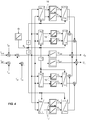
- stator flux induced voltages are functions of 2 ⁇ . This means that for a PMSM motor with a magnetized rotor, it is only possible to detect the position the magnetic flux of the rotor, but not its orientation or polarity (ambiguity 0- ⁇ ). However, if the motor M has projections, it is still possible to detect the orientation of the magnetic flux by using the improvement of the determination method illustrated in FIG. figure 4 .
- the current injection is carried out not only with a first and second injection frequency equal to respectively ⁇ and - ⁇ , but also with a third and a fourth injection frequency equal to twice the first frequency ⁇ and the second frequency - ⁇ .
- the method therefore also provides for injecting a third current vector according to a third current injection mark X + , Y + , this third reference X + , Y + rotating at the injection frequency 2 ⁇ with respect to the reference reference d , q and a fourth current vector in a fourth current injection mark X - , Y - rotating at the -2 ⁇ injection frequency with respect to the reference reference d, q.
- the third current vector is of amplitude I 1
- the fourth current vector is of amplitude I 2 .
- the control module 10 also comprises a third integrator module (Integral) 16 which is synchronous with the third reference X + , Y + , and a fourth integrator module (Integral) 17 which is synchronous with the fourth reference X - , Y - 16,17 each integrating module being composed of two integrators, as shown in figure 4 .
- a third integrator module Integral 16 which is synchronous with the third reference X + , Y +
- a fourth integrator module (Integral) 17 which is synchronous with the fourth reference X - , Y - 16,17 each integrating module being composed of two integrators, as shown in figure 4 .
- the third integrator module 16 outputs a third stator flux induced voltage V + which is decomposed into two components V X + and V Y + in the third reference X + , Y + .
- the fourth integrator module 16 outputs a fourth stator flux induced voltage V - which is decomposed into two components V X- and V Y- in the fourth frame X - , Y - .
- the determination method described in the invention is also feasible with an induction motor, for example an asynchronous motor.
- an induction motor for example an asynchronous motor.
- the first stator flux induced voltage U + and the second stator flux induced voltage U - are also a function of the angular position error ⁇ of the rotor flux vector.
- the two embodiments described above are therefore usable with an induction motor.
- the current injection is carried out with an amplitude I 1 of the component in the x + , y + reference which is equal to I and an amplitude I 2 of the component in the reference x - , y - which is equal to zero.
- the current injection is therefore done only by means of a current vector rotating at a positive injection frequency ⁇ .
- Current injection at a negative frequency is regulated at zero.
- the real part U x- of the second stator flux induced voltage U - is proportional to the error ⁇ , according to the following formula:
- the real part of the second induced stator flux induced voltage U ⁇ is proportional to the error ⁇ according to the following formula:
Landscapes
- Engineering & Computer Science (AREA)
- Power Engineering (AREA)
- Control Of Ac Motors In General (AREA)
Claims (8)
- Verfahren zur Positionsbestimmung eines Rotorflussvektors eines Elektromotors (M) mit einem Stator und einem Rotor, dadurch gekennzeichnet, dass das Verfahren umfasst:- einen Schritt des Injizierens eines ersten Stromvektors in eine erste Injektionsmarkierung (x+, y+), die sich mit einer ersten Frequenz (Ω) relativ zu einer Referenzmarkierung (d, q) synchron mit der Motordrehung dreht, und eines zweiten Stromvektors in eine zweite Injektionsmarkierung (x-, y-), die sich mit einer zweiten Frequenz relativ zu der Referenzmarkierung (d, q) dreht, wobei die zweite Frequenz entgegengesetzt zur ersten Frequenz ist,- einen Schritt des Bestimmens einer ersten durch den Statorfluss induzierten Spannung, die am Ausgang eines ersten Integratormoduls (12) synchron mit der ersten Injektionsmarkierung (x+, y+) ausgegeben wird, und einer zweiten durch den Statorfluss induzierten Spannung, die am Ausgang eines zweiten Integratormoduls (13) synchron mit der zweiten Injektionsmarkierung (x-,y-) ausgegeben wird,- einen Schritt des Regulierens der Position des Rotorflussvektors durch Minimieren der Abweichung (ε) zwischen einer tatsächlichen Position (θR) des Rotorflussvektors und einer geschätzten Position (θS) des Rotorflussvektors, wobei die Abweichung (ε) ausgehend von der zweiten durch den Statorfluss induzierten Spannung bestimmt wird.
- Verfahren zur Bestimmung nach Anspruch 1, dadurch gekennzeichnet, dass die Abweichung (ε) ausgehend von der ersten durch den Statorfluss induzierten Spannung und der zweiten durch den Statorfluss induzierten Spannung bestimmt wird.
- Verfahren zur Bestimmung nach Anspruch 2, dadurch gekennzeichnet, dass die Amplitude (I2) des zweiten Stromvektors gleich der Amplitude (I1) des ersten Stromvektors ist.
- Verfahren zur Bestimmung nach Anspruch 1, dadurch gekennzeichnet, dass die Amplitude (I2) des zweiten Stromvektors Null beträgt.
- Verfahren zur Bestimmung nach einem der Ansprüche 1 bis 4, dadurch gekennzeichnet, dass es sich bei dem Elektromotor (M) um einen Induktionsmotor handelt.
- Verfahren zur Bestimmung nach einem der Ansprüche 1 bis 4, dadurch gekennzeichnet, dass es sich bei dem Elektromotor (M) um einen Synchronmotor handelt.
- Verfahren zur Bestimmung nach Anspruch 6, dadurch gekennzeichnet, dass das Verfahren einen Schritt des Injizierens eines dritten Stromvektors in eine dritte Injektionsmarkierung (X+,Y+), die sich mit einer dritten Frequenz relativ zu der Referenzmarkierung (d, q) dreht, und eines vierten Stromvektors in eine vierte Injektionsmarkierung (X-,Y-), die sich mit einer vierten Frequenz relativ zu der Referenzmarkierung (d, q) dreht, umfasst, wobei die vierte Frequenz entgegengesetzt zur dritten Frequenz ist und die dritte Frequenz das Doppelte der ersten Frequenz beträgt.
- Drehzahlregler, der dazu bestimmt ist, einen Elektromotor (M) mit einem Stator und einem Rotor zu steuern, wobei der Regler ein Wechselrichtermodul (20) und ein Steuermodul (10) zum Steuern des Wechselrichtermoduls (20) umfasst, wobei das Steuermodul (10) ein erstes Integratormodul (12) und ein zweites Integratormodul (13) umfasst, dadurch gekennzeichnet, dass der Drehzahlregler ein Verfahren ausführt, das umfasst:- einen Schritt des Injizierens eines ersten Stromvektors in eine erste Injektionsmarkierung (x+, y+), die sich mit einer ersten Frequenz (Ω) relativ zu einer Referenzmarkierung (d, q) synchron mit der Drehung des Motors (M) dreht, und eines zweiten Stromvektors in eine zweite Injektionsmarkierung (x-,y-), die sich mit einer zweiten Frequenz relativ zu der Referenzmarkierung (d, q) dreht, wobei die zweite Frequenz entgegengesetzt zur ersten Frequenz ist,- einen Schritt des Bestimmens einer ersten durch den Statorfluss induzierten Spannung, die am Ausgang des ersten Integratormoduls (12) synchron mit der ersten Injektionsmarkierung (x+, y+) ausgegeben wird, und einer zweiten durch den Statorfluss induzierten Spannung, die am Ausgang des zweiten Integratormoduls (13) synchron mit der zweiten Injektionsmarkierung (x-,y-) ausgegeben wird,- einen Schritt des Regulierens der Position des Rotorflussvektors durch Minimieren der Abweichung (ε) zwischen einer tatsächlichen Position (θR) des Rotorflussvektors und einer geschätzten Position (θS) des Rotorflussvektors, wobei die Abweichung (ε) ausgehend von der zweiten durch den Statorfluss induzierten Spannung bestimmt wird.
Applications Claiming Priority (1)
| Application Number | Priority Date | Filing Date | Title |
|---|---|---|---|
| FR0952584A FR2944659B1 (fr) | 2009-04-21 | 2009-04-21 | Procede de determination de la position du vecteur de flux d'un moteur |
Publications (3)
| Publication Number | Publication Date |
|---|---|
| EP2246973A2 EP2246973A2 (de) | 2010-11-03 |
| EP2246973A3 EP2246973A3 (de) | 2016-02-17 |
| EP2246973B1 true EP2246973B1 (de) | 2018-05-30 |
Family
ID=41600418
Family Applications (1)
| Application Number | Title | Priority Date | Filing Date |
|---|---|---|---|
| EP10159258.2A Active EP2246973B1 (de) | 2009-04-21 | 2010-04-07 | Verfahren zur Positionsbestimmung des Flussvektors eines Motors |
Country Status (6)
| Country | Link |
|---|---|
| US (1) | US8330403B2 (de) |
| EP (1) | EP2246973B1 (de) |
| JP (1) | JP5490601B2 (de) |
| CN (1) | CN101873096B (de) |
| ES (1) | ES2680898T3 (de) |
| FR (1) | FR2944659B1 (de) |
Families Citing this family (22)
| Publication number | Priority date | Publication date | Assignee | Title |
|---|---|---|---|---|
| DE102009039672B4 (de) * | 2009-09-02 | 2024-03-07 | Sew-Eurodrive Gmbh & Co Kg | Verfahren zur Bestimmung der Rotorlage einer feldorientiert betriebenen Synchronmaschine |
| EP2552014A3 (de) * | 2011-07-28 | 2016-08-17 | Vestas Wind Systems A/S | Verfahren zur Positionierung einer sensorlosen Steuerung einer Elektromaschine |
| FR2992121B1 (fr) * | 2012-06-13 | 2015-06-26 | Schneider Toshiba Inverter | Systeme de commande d'un moteur electrique synchrone |
| US9431947B2 (en) | 2014-09-24 | 2016-08-30 | Texas Instruments Incorporated | Input vector set for position detection of PM motors |
| RU2582201C1 (ru) * | 2014-12-24 | 2016-04-20 | Федеральное государственное бюджетное образовательное учреждение высшего профессионального образования Липецкий государственный технический университет (ЛГТУ) | Способ стабилизации частоты вращения синхронного двигателя |
| FR3038469B1 (fr) * | 2015-07-01 | 2017-06-23 | Schneider Toshiba Inverter Europe Sas | Procede de commande pour le demarrage d'un moteur electrique synchrone |
| US10084399B2 (en) * | 2016-06-22 | 2018-09-25 | Faraday & Future Inc. | Detecting position measurement errors in an electric motor system |
| EP3337031B1 (de) | 2016-12-13 | 2020-06-17 | ABB Schweiz AG | Verfahren und vorrichtung zur detektion der anwesenheit eines dauermagneten eines rotors einer synchronmaschine |
| CN106788083B (zh) * | 2016-12-30 | 2019-06-11 | 苏州科技大学 | 交流永磁同步电机转子的位置识别方法 |
| EP3462599A1 (de) * | 2017-09-28 | 2019-04-03 | Siemens Aktiengesellschaft | Elektrische maschine |
| CN107947668A (zh) * | 2017-12-25 | 2018-04-20 | 雷勃电气(常州)有限公司 | 一种用于检测电机运行前状态的方法 |
| CN108054971A (zh) * | 2017-12-26 | 2018-05-18 | 顺丰科技有限公司 | 一种电机转子磁极极性判断方法及装置 |
| CN108574440A (zh) * | 2018-04-26 | 2018-09-25 | 江苏大学 | 一种基于滑模参考自适应的永磁同步电机状态估计方法 |
| EP3809578B1 (de) * | 2019-10-15 | 2024-08-21 | ABB Schweiz AG | Verfahren zum starten eines synchronmotors |
| CN110932636B (zh) * | 2019-12-16 | 2021-11-02 | 合肥阳光电动力科技有限公司 | 一种永磁同步电机初始位置辨识方法及系统 |
| US11394327B2 (en) | 2020-04-24 | 2022-07-19 | Borgwarner Inc. | Methods and systems for detecting a rotor position and rotor speed of an alternating current electrical machine |
| CN111800039B (zh) * | 2020-06-20 | 2022-02-01 | 珠海格力节能环保制冷技术研究中心有限公司 | 转子位置信息确认方法、同步电机的矢量控制方法及装置 |
| EP3936737B1 (de) | 2020-07-06 | 2024-02-07 | Ningbo Geely Automobile Research & Development Co., Ltd. | Ein verfahren zum betrieb eines fahrzeugantriebsstrangs |
| EP4248558A4 (de) * | 2020-11-17 | 2024-10-02 | Economotor Innovation Ltd | Verfahren und vorrichtung zur synchronmotorsteuerung |
| CN112713836B (zh) * | 2020-11-25 | 2022-11-01 | 东风汽车集团有限公司 | 一种电机零点标定装置和方法 |
| US11773962B1 (en) | 2022-03-28 | 2023-10-03 | Borgwarner Inc. | Electric drive unit with integrated, variable flow, low-pressure oil cooling system |
| DE102022118125A1 (de) | 2022-06-30 | 2024-01-04 | Schaeffler Technologies AG & Co. KG | Verfahren zum Betrieb eines Elektromotors |
Family Cites Families (10)
| Publication number | Priority date | Publication date | Assignee | Title |
|---|---|---|---|---|
| US6639380B2 (en) * | 2000-07-14 | 2003-10-28 | Sul Seung-Ki | Method and system of sensorless field orientation control for an AC motor |
| US6636012B2 (en) * | 2001-09-28 | 2003-10-21 | Rockwell Automation Technologies, Inc. | Stator and rotor resistance identifier using high frequency injection |
| JP4154149B2 (ja) * | 2001-12-28 | 2008-09-24 | 株式会社東芝 | ベクトル制御インバータ装置 |
| US6659726B2 (en) * | 2001-12-31 | 2003-12-09 | Carrier Corporation | Variable speed control of multiple motors |
| JP4370754B2 (ja) * | 2002-04-02 | 2009-11-25 | 株式会社安川電機 | 交流電動機のセンサレス制御装置および制御方法 |
| KR100645807B1 (ko) * | 2004-12-06 | 2007-02-28 | 엘지전자 주식회사 | 모터 기동 제어장치 및 그 방법 |
| EP1901421A1 (de) * | 2006-09-13 | 2008-03-19 | ABB Schweiz AG | Verfahren zum Bestimmen der Rotorwinkelposition einer rotierenden elektrischen Maschine |
| JP5109416B2 (ja) * | 2007-03-06 | 2012-12-26 | 株式会社デンソー | 回転機の制御装置 |
| DE602007008045D1 (de) * | 2007-01-12 | 2010-09-09 | Abb Oy | Verfahren zur Schätzung der Rotordrehzahl und Position einer synchronen Permanentmagnetmaschine ohne Lagegeber |
| JP2008206330A (ja) * | 2007-02-21 | 2008-09-04 | Meidensha Corp | 同期電動機の磁極位置推定装置および磁極位置推定方法 |
-
2009
- 2009-04-21 FR FR0952584A patent/FR2944659B1/fr not_active Expired - Fee Related
-
2010
- 2010-04-07 EP EP10159258.2A patent/EP2246973B1/de active Active
- 2010-04-07 ES ES10159258.2T patent/ES2680898T3/es active Active
- 2010-04-16 US US12/761,907 patent/US8330403B2/en active Active
- 2010-04-21 CN CN201010170336.4A patent/CN101873096B/zh active Active
- 2010-04-21 JP JP2010097905A patent/JP5490601B2/ja active Active
Non-Patent Citations (1)
| Title |
|---|
| None * |
Also Published As
| Publication number | Publication date |
|---|---|
| CN101873096B (zh) | 2014-10-29 |
| EP2246973A3 (de) | 2016-02-17 |
| JP2010259323A (ja) | 2010-11-11 |
| FR2944659B1 (fr) | 2011-04-01 |
| US8330403B2 (en) | 2012-12-11 |
| CN101873096A (zh) | 2010-10-27 |
| EP2246973A2 (de) | 2010-11-03 |
| JP5490601B2 (ja) | 2014-05-14 |
| ES2680898T3 (es) | 2018-09-11 |
| US20100264861A1 (en) | 2010-10-21 |
| FR2944659A1 (fr) | 2010-10-22 |
Similar Documents
| Publication | Publication Date | Title |
|---|---|---|
| EP2246973B1 (de) | Verfahren zur Positionsbestimmung des Flussvektors eines Motors | |
| EP2845311B1 (de) | Verfahren zur bestimmung des winkelversatzes zwischen dem rotor und stator einer elektrischen maschine eines kraftfahrzeugs | |
| EP2684289B1 (de) | In einem stromwandler implementiertes steuerverfahren zur identifizierung von parametern in bezug auf die magnetische sättigung eines elektromotors | |
| FR2843659A1 (fr) | Procede d'utilisation d'un dispositif d'observation de parametres en boucle ouverte pour la commande d'un moteur a aimant permanent | |
| EP2870018B1 (de) | Verfahren zur steuerung eines antriebsstranges und entsprechendes system | |
| EP2963802B1 (de) | Steuerungsverfahren zum anlassen eines elektrischen synchronmotors | |
| EP3560095B1 (de) | Verfahren zum bestimmen einer direktachseninduktivität und einer quadraturachseninduktivität einer elektrischen maschine, entsprechendes computerprogramm und vorrichtung | |
| EP2787632B1 (de) | Verfahren und Vorrichtung zum Steuern einer doppelten elektrisch umlaufenden Maschine mit Drehstromantrieb, und entsprechende elektrisch umlaufende Maschine | |
| EP4416835B1 (de) | Verfahren zur schätzung der position und geschwindigkeit des rotors eines permanentmagnet-synchronmotors | |
| EP3012962A1 (de) | Steuerungsverfahren einer synchronlaufenden drehstrom-elektromaschine mit schleifringläufer | |
| EP3192164A1 (de) | System und verfahren zur steuerung einer elektrischen asynchronmaschine | |
| EP3824540B1 (de) | Positions und geschwindigkeitsbestimmung eines wickelrotor einer elektrischen synchronmaschine verfahren | |
| EP3128667B1 (de) | Steuerungsverfahren zum anlassen eines elektrischen synchronmotors | |
| WO2023073317A1 (fr) | Procédé de calage automatique d'un capteur de position angulaire | |
| EP2803135B1 (de) | Steuerverfahren, zur steuerung zweier elektrischer permanentmagnet-synchronmotoren in parallelschaltung | |
| EP3928426B1 (de) | Verfahren zur schätzung des drehmoments einer elektrischen synchronmaschine | |
| EP2992602B1 (de) | Verfahren zur überprüfung der funktionsfähigkeit einer antriebseinheit für ein kraftfahrzeug und entsprechendes system | |
| FR3160463A1 (fr) | Méthode de détermination de la position angulaire d’un rotor de machine électrique | |
| EP4128521A2 (de) | Verfahren zur steuerung eines gleichrichters, der an einen permanent-magnet-synchrongenerator angeschlossen ist, um eine gleichspannung bereitzustellen, entsprechende vorrichtung und computerprogramm | |
| FR2921212A1 (fr) | Demarreur/generatrice muni d'un indicateur de position de generatrice a aimants permanents |
Legal Events
| Date | Code | Title | Description |
|---|---|---|---|
| PUAI | Public reference made under article 153(3) epc to a published international application that has entered the european phase |
Free format text: ORIGINAL CODE: 0009012 |
|
| AK | Designated contracting states |
Kind code of ref document: A2 Designated state(s): AT BE BG CH CY CZ DE DK EE ES FI FR GB GR HR HU IE IS IT LI LT LU LV MC MK MT NL NO PL PT RO SE SI SK SM TR |
|
| AX | Request for extension of the european patent |
Extension state: AL BA ME RS |
|
| PUAL | Search report despatched |
Free format text: ORIGINAL CODE: 0009013 |
|
| AK | Designated contracting states |
Kind code of ref document: A3 Designated state(s): AT BE BG CH CY CZ DE DK EE ES FI FR GB GR HR HU IE IS IT LI LT LU LV MC MK MT NL NO PL PT RO SE SI SK SM TR |
|
| AX | Request for extension of the european patent |
Extension state: AL BA ME RS |
|
| RIC1 | Information provided on ipc code assigned before grant |
Ipc: H02P 21/00 20160101ALI20160112BHEP Ipc: H02P 21/14 20060101ALI20160112BHEP Ipc: H02P 21/04 20060101AFI20160112BHEP |
|
| 17P | Request for examination filed |
Effective date: 20160225 |
|
| RBV | Designated contracting states (corrected) |
Designated state(s): AT BE BG CH CY CZ DE DK EE ES FI FR GB GR HR HU IE IS IT LI LT LU LV MC MK MT NL NO PL PT RO SE SI SK SM TR |
|
| REG | Reference to a national code |
Ref country code: DE Ref legal event code: R079 Ref document number: 602010050867 Country of ref document: DE Free format text: PREVIOUS MAIN CLASS: H02P0021040000 Ipc: H02P0021320000 |
|
| GRAP | Despatch of communication of intention to grant a patent |
Free format text: ORIGINAL CODE: EPIDOSNIGR1 |
|
| STAA | Information on the status of an ep patent application or granted ep patent |
Free format text: STATUS: GRANT OF PATENT IS INTENDED |
|
| RIC1 | Information provided on ipc code assigned before grant |
Ipc: H02P 21/14 20160101ALI20180216BHEP Ipc: H02P 21/00 20160101ALI20180216BHEP Ipc: H02P 21/18 20160101ALI20180216BHEP Ipc: H02P 21/32 20160101AFI20180216BHEP Ipc: H02P 21/04 20060101ALI20180216BHEP |
|
| INTG | Intention to grant announced |
Effective date: 20180316 |
|
| GRAS | Grant fee paid |
Free format text: ORIGINAL CODE: EPIDOSNIGR3 |
|
| GRAA | (expected) grant |
Free format text: ORIGINAL CODE: 0009210 |
|
| STAA | Information on the status of an ep patent application or granted ep patent |
Free format text: STATUS: THE PATENT HAS BEEN GRANTED |
|
| AK | Designated contracting states |
Kind code of ref document: B1 Designated state(s): AT BE BG CH CY CZ DE DK EE ES FI FR GB GR HR HU IE IS IT LI LT LU LV MC MK MT NL NO PL PT RO SE SI SK SM TR |
|
| REG | Reference to a national code |
Ref country code: GB Ref legal event code: FG4D Free format text: NOT ENGLISH |
|
| REG | Reference to a national code |
Ref country code: CH Ref legal event code: EP |
|
| REG | Reference to a national code |
Ref country code: AT Ref legal event code: REF Ref document number: 1004632 Country of ref document: AT Kind code of ref document: T Effective date: 20180615 |
|
| REG | Reference to a national code |
Ref country code: IE Ref legal event code: FG4D Free format text: LANGUAGE OF EP DOCUMENT: FRENCH |
|
| REG | Reference to a national code |
Ref country code: DE Ref legal event code: R096 Ref document number: 602010050867 Country of ref document: DE |
|
| REG | Reference to a national code |
Ref country code: ES Ref legal event code: FG2A Ref document number: 2680898 Country of ref document: ES Kind code of ref document: T3 Effective date: 20180911 |
|
| REG | Reference to a national code |
Ref country code: NL Ref legal event code: MP Effective date: 20180530 |
|
| REG | Reference to a national code |
Ref country code: LT Ref legal event code: MG4D |
|
| PG25 | Lapsed in a contracting state [announced via postgrant information from national office to epo] |
Ref country code: LT Free format text: LAPSE BECAUSE OF FAILURE TO SUBMIT A TRANSLATION OF THE DESCRIPTION OR TO PAY THE FEE WITHIN THE PRESCRIBED TIME-LIMIT Effective date: 20180530 Ref country code: CY Free format text: LAPSE BECAUSE OF FAILURE TO SUBMIT A TRANSLATION OF THE DESCRIPTION OR TO PAY THE FEE WITHIN THE PRESCRIBED TIME-LIMIT Effective date: 20180530 Ref country code: NO Free format text: LAPSE BECAUSE OF FAILURE TO SUBMIT A TRANSLATION OF THE DESCRIPTION OR TO PAY THE FEE WITHIN THE PRESCRIBED TIME-LIMIT Effective date: 20180830 Ref country code: FI Free format text: LAPSE BECAUSE OF FAILURE TO SUBMIT A TRANSLATION OF THE DESCRIPTION OR TO PAY THE FEE WITHIN THE PRESCRIBED TIME-LIMIT Effective date: 20180530 Ref country code: BG Free format text: LAPSE BECAUSE OF FAILURE TO SUBMIT A TRANSLATION OF THE DESCRIPTION OR TO PAY THE FEE WITHIN THE PRESCRIBED TIME-LIMIT Effective date: 20180830 Ref country code: SE Free format text: LAPSE BECAUSE OF FAILURE TO SUBMIT A TRANSLATION OF THE DESCRIPTION OR TO PAY THE FEE WITHIN THE PRESCRIBED TIME-LIMIT Effective date: 20180530 |
|
| PG25 | Lapsed in a contracting state [announced via postgrant information from national office to epo] |
Ref country code: GR Free format text: LAPSE BECAUSE OF FAILURE TO SUBMIT A TRANSLATION OF THE DESCRIPTION OR TO PAY THE FEE WITHIN THE PRESCRIBED TIME-LIMIT Effective date: 20180831 Ref country code: HR Free format text: LAPSE BECAUSE OF FAILURE TO SUBMIT A TRANSLATION OF THE DESCRIPTION OR TO PAY THE FEE WITHIN THE PRESCRIBED TIME-LIMIT Effective date: 20180530 Ref country code: LV Free format text: LAPSE BECAUSE OF FAILURE TO SUBMIT A TRANSLATION OF THE DESCRIPTION OR TO PAY THE FEE WITHIN THE PRESCRIBED TIME-LIMIT Effective date: 20180530 |
|
| REG | Reference to a national code |
Ref country code: AT Ref legal event code: MK05 Ref document number: 1004632 Country of ref document: AT Kind code of ref document: T Effective date: 20180530 |
|
| PG25 | Lapsed in a contracting state [announced via postgrant information from national office to epo] |
Ref country code: NL Free format text: LAPSE BECAUSE OF FAILURE TO SUBMIT A TRANSLATION OF THE DESCRIPTION OR TO PAY THE FEE WITHIN THE PRESCRIBED TIME-LIMIT Effective date: 20180530 |
|
| PG25 | Lapsed in a contracting state [announced via postgrant information from national office to epo] |
Ref country code: SK Free format text: LAPSE BECAUSE OF FAILURE TO SUBMIT A TRANSLATION OF THE DESCRIPTION OR TO PAY THE FEE WITHIN THE PRESCRIBED TIME-LIMIT Effective date: 20180530 Ref country code: RO Free format text: LAPSE BECAUSE OF FAILURE TO SUBMIT A TRANSLATION OF THE DESCRIPTION OR TO PAY THE FEE WITHIN THE PRESCRIBED TIME-LIMIT Effective date: 20180530 Ref country code: CZ Free format text: LAPSE BECAUSE OF FAILURE TO SUBMIT A TRANSLATION OF THE DESCRIPTION OR TO PAY THE FEE WITHIN THE PRESCRIBED TIME-LIMIT Effective date: 20180530 Ref country code: DK Free format text: LAPSE BECAUSE OF FAILURE TO SUBMIT A TRANSLATION OF THE DESCRIPTION OR TO PAY THE FEE WITHIN THE PRESCRIBED TIME-LIMIT Effective date: 20180530 Ref country code: EE Free format text: LAPSE BECAUSE OF FAILURE TO SUBMIT A TRANSLATION OF THE DESCRIPTION OR TO PAY THE FEE WITHIN THE PRESCRIBED TIME-LIMIT Effective date: 20180530 Ref country code: AT Free format text: LAPSE BECAUSE OF FAILURE TO SUBMIT A TRANSLATION OF THE DESCRIPTION OR TO PAY THE FEE WITHIN THE PRESCRIBED TIME-LIMIT Effective date: 20180530 Ref country code: PL Free format text: LAPSE BECAUSE OF FAILURE TO SUBMIT A TRANSLATION OF THE DESCRIPTION OR TO PAY THE FEE WITHIN THE PRESCRIBED TIME-LIMIT Effective date: 20180530 |
|
| PG25 | Lapsed in a contracting state [announced via postgrant information from national office to epo] |
Ref country code: SM Free format text: LAPSE BECAUSE OF FAILURE TO SUBMIT A TRANSLATION OF THE DESCRIPTION OR TO PAY THE FEE WITHIN THE PRESCRIBED TIME-LIMIT Effective date: 20180530 |
|
| REG | Reference to a national code |
Ref country code: DE Ref legal event code: R097 Ref document number: 602010050867 Country of ref document: DE |
|
| PLBE | No opposition filed within time limit |
Free format text: ORIGINAL CODE: 0009261 |
|
| STAA | Information on the status of an ep patent application or granted ep patent |
Free format text: STATUS: NO OPPOSITION FILED WITHIN TIME LIMIT |
|
| 26N | No opposition filed |
Effective date: 20190301 |
|
| PG25 | Lapsed in a contracting state [announced via postgrant information from national office to epo] |
Ref country code: SI Free format text: LAPSE BECAUSE OF FAILURE TO SUBMIT A TRANSLATION OF THE DESCRIPTION OR TO PAY THE FEE WITHIN THE PRESCRIBED TIME-LIMIT Effective date: 20180530 |
|
| REG | Reference to a national code |
Ref country code: CH Ref legal event code: PL |
|
| REG | Reference to a national code |
Ref country code: BE Ref legal event code: MM Effective date: 20190430 |
|
| PG25 | Lapsed in a contracting state [announced via postgrant information from national office to epo] |
Ref country code: LU Free format text: LAPSE BECAUSE OF NON-PAYMENT OF DUE FEES Effective date: 20190407 Ref country code: MC Free format text: LAPSE BECAUSE OF FAILURE TO SUBMIT A TRANSLATION OF THE DESCRIPTION OR TO PAY THE FEE WITHIN THE PRESCRIBED TIME-LIMIT Effective date: 20180530 |
|
| PG25 | Lapsed in a contracting state [announced via postgrant information from national office to epo] |
Ref country code: LI Free format text: LAPSE BECAUSE OF NON-PAYMENT OF DUE FEES Effective date: 20190430 Ref country code: CH Free format text: LAPSE BECAUSE OF NON-PAYMENT OF DUE FEES Effective date: 20190430 |
|
| PG25 | Lapsed in a contracting state [announced via postgrant information from national office to epo] |
Ref country code: BE Free format text: LAPSE BECAUSE OF NON-PAYMENT OF DUE FEES Effective date: 20190430 |
|
| PG25 | Lapsed in a contracting state [announced via postgrant information from national office to epo] |
Ref country code: TR Free format text: LAPSE BECAUSE OF FAILURE TO SUBMIT A TRANSLATION OF THE DESCRIPTION OR TO PAY THE FEE WITHIN THE PRESCRIBED TIME-LIMIT Effective date: 20180530 |
|
| PG25 | Lapsed in a contracting state [announced via postgrant information from national office to epo] |
Ref country code: IE Free format text: LAPSE BECAUSE OF NON-PAYMENT OF DUE FEES Effective date: 20190407 |
|
| PG25 | Lapsed in a contracting state [announced via postgrant information from national office to epo] |
Ref country code: PT Free format text: LAPSE BECAUSE OF FAILURE TO SUBMIT A TRANSLATION OF THE DESCRIPTION OR TO PAY THE FEE WITHIN THE PRESCRIBED TIME-LIMIT Effective date: 20181001 |
|
| PG25 | Lapsed in a contracting state [announced via postgrant information from national office to epo] |
Ref country code: IS Free format text: LAPSE BECAUSE OF FAILURE TO SUBMIT A TRANSLATION OF THE DESCRIPTION OR TO PAY THE FEE WITHIN THE PRESCRIBED TIME-LIMIT Effective date: 20180930 |
|
| PG25 | Lapsed in a contracting state [announced via postgrant information from national office to epo] |
Ref country code: MT Free format text: LAPSE BECAUSE OF FAILURE TO SUBMIT A TRANSLATION OF THE DESCRIPTION OR TO PAY THE FEE WITHIN THE PRESCRIBED TIME-LIMIT Effective date: 20180530 Ref country code: HU Free format text: LAPSE BECAUSE OF FAILURE TO SUBMIT A TRANSLATION OF THE DESCRIPTION OR TO PAY THE FEE WITHIN THE PRESCRIBED TIME-LIMIT; INVALID AB INITIO Effective date: 20100407 |
|
| PG25 | Lapsed in a contracting state [announced via postgrant information from national office to epo] |
Ref country code: MK Free format text: LAPSE BECAUSE OF FAILURE TO SUBMIT A TRANSLATION OF THE DESCRIPTION OR TO PAY THE FEE WITHIN THE PRESCRIBED TIME-LIMIT Effective date: 20180530 |
|
| PGFP | Annual fee paid to national office [announced via postgrant information from national office to epo] |
Ref country code: DE Payment date: 20250428 Year of fee payment: 16 |
|
| PGFP | Annual fee paid to national office [announced via postgrant information from national office to epo] |
Ref country code: ES Payment date: 20250513 Year of fee payment: 16 Ref country code: GB Payment date: 20250422 Year of fee payment: 16 |
|
| PGFP | Annual fee paid to national office [announced via postgrant information from national office to epo] |
Ref country code: IT Payment date: 20250422 Year of fee payment: 16 |
|
| PGFP | Annual fee paid to national office [announced via postgrant information from national office to epo] |
Ref country code: FR Payment date: 20250424 Year of fee payment: 16 |