EP3709394B1 - Hocheffiziente elektrochemische stromversorgungsquelle für ein unterwasserfahrzeug - Google Patents
Hocheffiziente elektrochemische stromversorgungsquelle für ein unterwasserfahrzeug Download PDFInfo
- Publication number
- EP3709394B1 EP3709394B1 EP20162922.7A EP20162922A EP3709394B1 EP 3709394 B1 EP3709394 B1 EP 3709394B1 EP 20162922 A EP20162922 A EP 20162922A EP 3709394 B1 EP3709394 B1 EP 3709394B1
- Authority
- EP
- European Patent Office
- Prior art keywords
- tank
- temperature
- electrolytic fluid
- inlet
- power supply
- Prior art date
- Legal status (The legal status is an assumption and is not a legal conclusion. Google has not performed a legal analysis and makes no representation as to the accuracy of the status listed.)
- Active
Links
Images

Classifications
-
- H—ELECTRICITY
- H01—ELECTRIC ELEMENTS
- H01M—PROCESSES OR MEANS, e.g. BATTERIES, FOR THE DIRECT CONVERSION OF CHEMICAL ENERGY INTO ELECTRICAL ENERGY
- H01M6/00—Primary cells; Manufacture thereof
- H01M6/30—Deferred-action cells
- H01M6/32—Deferred-action cells activated through external addition of electrolyte or of electrolyte components
- H01M6/34—Immersion cells, e.g. sea-water cells
-
- H—ELECTRICITY
- H01—ELECTRIC ELEMENTS
- H01M—PROCESSES OR MEANS, e.g. BATTERIES, FOR THE DIRECT CONVERSION OF CHEMICAL ENERGY INTO ELECTRICAL ENERGY
- H01M50/00—Constructional details or processes of manufacture of the non-active parts of electrochemical cells other than fuel cells, e.g. hybrid cells
- H01M50/70—Arrangements for stirring or circulating the electrolyte
-
- B—PERFORMING OPERATIONS; TRANSPORTING
- B63—SHIPS OR OTHER WATERBORNE VESSELS; RELATED EQUIPMENT
- B63G—OFFENSIVE OR DEFENSIVE ARRANGEMENTS ON VESSELS; MINE-LAYING; MINE-SWEEPING; SUBMARINES; AIRCRAFT CARRIERS
- B63G8/00—Underwater vessels, e.g. submarines; Equipment specially adapted therefor
- B63G8/08—Propulsion
-
- G—PHYSICS
- G05—CONTROLLING; REGULATING
- G05D—SYSTEMS FOR CONTROLLING OR REGULATING NON-ELECTRIC VARIABLES
- G05D11/00—Control of flow ratio
- G05D11/16—Controlling mixing ratio of fluids having different temperatures, e.g. by sensing the temperature of a mixture of fluids having different viscosities
-
- G—PHYSICS
- G05—CONTROLLING; REGULATING
- G05D—SYSTEMS FOR CONTROLLING OR REGULATING NON-ELECTRIC VARIABLES
- G05D23/00—Control of temperature
- G05D23/01—Control of temperature without auxiliary power
- G05D23/13—Control of temperature without auxiliary power by varying the mixing ratio of two fluids having different temperatures
- G05D23/1393—Control of temperature without auxiliary power by varying the mixing ratio of two fluids having different temperatures characterised by the use of electric means
-
- H—ELECTRICITY
- H01—ELECTRIC ELEMENTS
- H01M—PROCESSES OR MEANS, e.g. BATTERIES, FOR THE DIRECT CONVERSION OF CHEMICAL ENERGY INTO ELECTRICAL ENERGY
- H01M50/00—Constructional details or processes of manufacture of the non-active parts of electrochemical cells other than fuel cells, e.g. hybrid cells
- H01M50/70—Arrangements for stirring or circulating the electrolyte
- H01M50/77—Arrangements for stirring or circulating the electrolyte with external circulating path
-
- H—ELECTRICITY
- H01—ELECTRIC ELEMENTS
- H01M—PROCESSES OR MEANS, e.g. BATTERIES, FOR THE DIRECT CONVERSION OF CHEMICAL ENERGY INTO ELECTRICAL ENERGY
- H01M6/00—Primary cells; Manufacture thereof
- H01M6/04—Cells with aqueous electrolyte
-
- H—ELECTRICITY
- H01—ELECTRIC ELEMENTS
- H01M—PROCESSES OR MEANS, e.g. BATTERIES, FOR THE DIRECT CONVERSION OF CHEMICAL ENERGY INTO ELECTRICAL ENERGY
- H01M6/00—Primary cells; Manufacture thereof
- H01M6/50—Methods or arrangements for servicing or maintenance, e.g. for maintaining operating temperature
- H01M6/5038—Heating or cooling of cells or batteries
-
- H—ELECTRICITY
- H01—ELECTRIC ELEMENTS
- H01M—PROCESSES OR MEANS, e.g. BATTERIES, FOR THE DIRECT CONVERSION OF CHEMICAL ENERGY INTO ELECTRICAL ENERGY
- H01M2220/00—Batteries for particular applications
- H01M2220/20—Batteries in motive systems, e.g. vehicle, ship, plane
-
- H—ELECTRICITY
- H01—ELECTRIC ELEMENTS
- H01M—PROCESSES OR MEANS, e.g. BATTERIES, FOR THE DIRECT CONVERSION OF CHEMICAL ENERGY INTO ELECTRICAL ENERGY
- H01M2300/00—Electrolytes
- H01M2300/0002—Aqueous electrolytes
Definitions
- the present invention relates to a high efficiency electrochemical power supply source, for use in a marine environment in an underwater vehicle, for example a torpedo.
- Electrochemical-type power supply sources for example of the aluminium-silver oxide (Al-AgO)type
- electrochemical-type power supply sources for example of the aluminium-silver oxide (Al-AgO)type
- Al-AgO aluminium-silver oxide
- Document US9450227B2 discloses a deferred action battery for marine applications comprising a battery stack (4), in which an electrolytic solution circulates, a first tank (6) containing a first electrolyte at a first temperature, a second tank (8) containing a second electrolyte at a second temperature and a thermostatic valve (14) for circulating into the battery stack a mixture of the first and the second electrolyte.
- Document US4752542A discloses a deferred action AgO/Al battery comprising a battery stack (2), a thermostatic valve (12), a first tank (31) containing a first electrolytic solution and a second tank (32) containing a second electrolytic solution.
- Document US2007111043A1 discloses a battery pack comprising lead-acid batteries, which are activated by (i) circulating a first electrolyte at a first concentration, which is contained in a first tank and subsequently (ii) letting circulate a second electrolyte at a higher concentration, which is contained in a second concentration.
- an electrochemical-type power supply source comprises an electrochemical stack, consisting of cells containing at least two electrodes (anode and cathode), typically made of metal materials with different electronegative potential, wherein an appropriate electrolytic fluid is circulated.
- Such electrolytic fluid undergoes a rise in temperature when it is inside the electrochemical stack, due to exothermic chemical reactions occurring inside the electrochemical stack for producing electric power.
- the electrolytic fluid is then generally extracted from the electrochemical stack and cooled by means of appropriate cooling systems, to avoid a system thermal drift, to be later re-introduced into the electrochemical stack.
- the temperature control of the electrolytic fluid introduced into the electrochemical stack represents an important parameter for the correct operation of the power supply source, being related to the electric power generated; in particular, it is known to adjust the electrolytic fluid temperature in order to generate a variable power depending on the needs of the underwater vehicle.
- an adjustment system which comprises a heat exchanger, two tanks designed to contain electrolytic fluid at a different temperature and a thermostatic valve with two mixing inlets.
- a first tank contains electrolytic fluid at a higher temperature, defined as “hot”, which is withdrawn from the electrochemical stack;
- a second tank contains instead electrolytic fluid at a lower temperature (defined as “cold”), obtained by means of appropriately cooling of the hot electrolytic fluid, which is flown through the heat exchanger.
- the thermostatic valve has a first and a second mixing inlets, connected respectively to the first and second tanks, a fluid outlet connected to an inlet of the electrochemical stack, and adjustment means actuatable to control mixing of the hot electrolytic fluid and cold electrolytic fluid, so as to adjust the temperature of the mixed electrolytic fluid to be supplied to the electrochemical stack.
- a low temperature is employed for low power (and low speeds) and a high temperature for high power (and high speeds).
- the drop in the electrolytic fluid temperature at low power allows to reduce internal losses (in particular, reducing energy absorption due to the so-called leakage currents) and therefore to preserve the stored energy for the vehicle actual "mission”.
- the possibility of reducing the temperature is however limited, in current applications, by the fact that in a transition mode, in case of a sudden request of high power (for example to allow performing a final manoeuvre of approaching a target, in case of a torpedo), the power supply source has to be able to supply the required power even from the low temperature levels at which the electrolytic fluid is, and this is possible only if the starting temperature is not too low.
- the object of the present invention is to provide a solution which allows to solve the previously highlighted problems and which allows in particular to improve the efficiency of an electrochemical power supply source and, consequently, the use range (in terms of launch duration and/or distance) of the associated underwater vehicle, with no need to require at a same time an increase in the power supply source size.
- an electrochemical power supply source is provided, as described in the appended claims.
- an aspect of the present solution envisages introducing an electrolytic fluid reserve (so called “super-hot”, namely at a very high temperature), contained in a specific auxiliary tank, having small size, which enables to increase the input temperature to the electrolytic stack in a short time (for example in the order of few seconds) thus enabling the electrochemical power supply to immediately activate a high-power condition making it possible for the corresponding underwater vehicle to perform manoeuvres with relevant speeds even starting from very low electrolytic fluid temperatures.
- an electrolytic fluid reserve so called “super-hot”
- auxiliary tank having small size
- an aspect of the present invention provides a direct connection of the aforesaid auxiliary tank with a mixing inlet of the thermostatic valve, which thus manages in a controlled way the direct injection of high-temperature electrolytic fluid into the electrochemical stack, during the transitory acceleration phase (with high power requirement).
- the present solution thus allows to preserve the acceleration range of the underwater vehicle even when the power supply source operates at lower temperatures; in other words, the electrolytic power supply source can operate within low temperature ranges (and therefore with high yields) that could not be obtained until today in case of low power, without jeopardising the "leap" to high power and maximum speed accelerations.
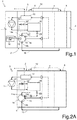
- Figure 1 shows an underwater vehicle, generally indicated by 1, for example a torpedo, comprising a tubular body, with a longitudinal extension axis A, having a central section inside which a chamber 2 is defined, housing an electrochemical power supply 3 which provides electric power supply to a propulsion engine of the underwater vehicle 1 (not illustrated herein) and/or to on board electronic apparatuses (also not illustrated).
- a torpedo comprising a tubular body, with a longitudinal extension axis A, having a central section inside which a chamber 2 is defined, housing an electrochemical power supply 3 which provides electric power supply to a propulsion engine of the underwater vehicle 1 (not illustrated herein) and/or to on board electronic apparatuses (also not illustrated).
- Such electrochemical power supply source 3 comprises an electrochemical stack 4, consisting, in a known way, of a certain number (so-called “stack") of electrochemical cells, designed, in use, to be filled with electrolytic fluid (for example a sodium hydroxide aqueous solution), to cause corresponding chemical reactions for generation of electric power.
- electrolytic fluid for example a sodium hydroxide aqueous solution
- the electrochemical power supply 3 has a first tank 6 (at the front of the electrochemical stack 4 with respect to the longitudinal axis A, also defined as “front tank”) and a second tank 8 (at the back of the same electrochemical stack 4 with respect to the longitudinal axis A, defined as “back tank”), designed to respectively contain a high-temperature electrolytic fluid (so-called “hot electrolytic fluid”) and a low-temperature electrolytic fluid (so-called “cold electrolytic fluid”).
- a high-temperature electrolytic fluid so-called “hot electrolytic fluid”
- cold electrolytic fluid low-temperature electrolytic fluid
- the hot electrolytic fluid, withdrawn from inside the electrochemical stack 4, is introduced into a separator 10, of the fluid-to-liquid-phase type, which has an inlet in fluidic communication with the aforesaid electrochemical stack 4, one first outlet coupled outside the underwater vehicle 1, for ejecting reaction gases, mainly hydrogen (H 2 ), and a second outlet for the outflow of the liquid, separated from the aforesaid reaction gases.
- a separator 10 of the fluid-to-liquid-phase type, which has an inlet in fluidic communication with the aforesaid electrochemical stack 4, one first outlet coupled outside the underwater vehicle 1, for ejecting reaction gases, mainly hydrogen (H 2 ), and a second outlet for the outflow of the liquid, separated from the aforesaid reaction gases.
- Such liquid is re-introduced into the first tank 6, pressurized by means of a pump 11, for example of the centrifugal type, which has an inlet coupled to the aforesaid second outlet of the separator 10 and a respective outlet coupled inside the first tank 6.
- Part of the hot electrolytic fluid contained in the first tank 6 is appropriately directed towards the inlet of a heat exchanger 12, which for example consists of a gap formed inside the central section of the underwater vehicle 1 and having an outer wall directly contacting the seawater outside the underwater vehicle 1.
- the heat exchanger 12 has an outlet fluidically connected with the inside of the second tank 8, such that the electrolytic fluid, once cooled, reaches the second tank 8.
- the pump 11 pressurizes the first tank 6, the second tank 8 and the aforesaid heat exchanger 12, which fluidically connects the first and second tanks 6, 8.
- the pump 11 is arranged outside the chamber 2, in an external portion, in a so-called “dry” zone, i.e. not contacting the electrolytic fluid and the seawater.
- the electrochemical power supply 3 also comprises a thermostatic valve 14, which allows mixing, at a desired quantity, of a lower-temperature electrolytic fluid with a higher-temperature electrolytic fluid, and introducing the mixed fluid, at a desired and controlled temperature, inside the electrochemical stack 4; in the illustrated embodiment, the thermostatic valve 14 is inside the first tank 6, immersed into the hot electrolytic fluid contained therein.
- the thermostatic valve 14 has: a first mixing inlet 14a fluidically connected to the first tank 6, consisting of an opening in fluidic communication with the first tank 6, by interposition of an appropriate filtering element, such as to receive the hot electrolytic fluid which is generated following the exothermic-type chemical reaction in the electrochemical stack 4 and which is extracted from the same electrochemical stack 4; a second mixing inlet 14b, fluidically connected to the second tank 8 by means of a connecting duct 16, such as to receive the electrolytic fluid appropriately cooled by the heat exchanger 12; and a fluid outlet 15, at which it provides electrolytic fluid mixed at temperature adjusted at a desired value, for introduction into the electrochemical stack 4.
- An electronic control module 18, comprising a microcontroller processing unit (or microprocessor, DSP - Digital Signal Processor, or similar digital processing element), is configured so as to provide a control signal S c to an actuator 19 of the thermostatic valve 14, adapted to appropriately choke the mixing inlets to obtain a desired adjustment of the temperature of the electrolytic fluid mixed at the fluid outlet 15.
- a microcontroller processing unit or microprocessor, DSP - Digital Signal Processor, or similar digital processing element
- the electronic control module 18 is arranged outside the chamber 2, in the "dry" zone, not contacting the electrolytic fluid and seawater.
- control module 18 can be configured so as to implement a closed-loop control of the actuator 19 of the thermostatic valve 14, depending on a reference signal (representing a target value for the outlet temperature and/or a target value of a magnitude associated to such outlet temperature, for example a desired electric power which has to be provided to the electrochemical power supply 3) and on one or more detection signals (provided for example by a temperature sensor, such as a thermocouple, coupled at the fluid outlet 15 to detect the outlet temperature of the electrolytic fluid resulting from the mixing by the thermostatic valve 14, and/or a position sensor coupled to the actuator 19 of the electrostatic valve 14, to detect an actuating position thereof).
- a reference signal representing a target value for the outlet temperature and/or a target value of a magnitude associated to such outlet temperature, for example a desired electric power which has to be provided to the electrochemical power supply 3
- detection signals provided for example by a temperature sensor, such as a thermocouple, coupled at the fluid outlet 15 to detect the outlet temperature of the electrolytic fluid resulting from the mixing
- the aforesaid reference signal can be for example generated by a main management electronic unit (not illustrated herein) of the underwater vehicle 1, for example based on the desired power which has to be provided by the electrochemical power supply source 3.
- the electrochemical power supply source 3 further comprises an auxiliary tank 20, designed to contain very hot or "super-hot” electrolytic fluid, i.e. at a very high temperature, higher (typically much higher)than the hot electrolytic fluid in the first tank 6.
- Such auxiliary tank 20 is provided with a watertight casing, immersed inside the electrolytic fluid contained in the first tank 6, from which it is kept watertight (note that the auxiliary tank 20 has small size, smaller than the first tank 6).
- the auxiliary tank 20 contains an electrolytic mixture, for example a mixture of sodium hydroxide powder and sodium oxide, at high concentration, such to cause a highly exothermic reaction when it is dissolved in a liquid and a consequent high rise in temperature (as will be discussed hereinafter).
- the electrochemical power supply source 3 comprises a hydraulic diverter element 22, coupled to the outlet of the pump 11, operable to divert at least part of the liquid delivered from the pump 11 towards the aforesaid auxiliary tank 20.
- such hydraulic diverter element 22 comprises a valve assembly 22', operable to direct all the liquid delivered from the pump 11 towards the first tank 6, in a normal operating condition of the electrochemical power supply source 3; and to divert the delivered liquid partly towards the first tank 6 and partly towards the auxiliary tank 20 in a different operating condition, so called "transition" mode, wherein the underwater vehicle 1 requires generation of a high electric power in a short time.
- the thermostatic valve 14 is of a three-way type, being provided with a third mixing inlet 14c, fluidically coupled inside the aforesaid auxiliary tank 20, by means of a valve element 23, to receive the very hot electrolytic fluid, during the transition operating condition.
- the thermostatic valve 14 is configured so as to switch the two mixing inlets (receiving the higher temperature and lower temperature electrolytic fluids), which are choked to mix the outlet electrolytic fluid and to adjust the temperature, in the transition operating condition with respect to the normal operating condition.
- the thermostatic valve 14 is configured so as to mix the electrolytic fluid received from the first mixing inlet 14a (hot fluid coming from the first tank 6), as a higher-temperature fluid, with the electrolytic fluid received from the second mixing inlet 14b (cold fluid coming from the second tank 8), as a lower-temperature fluid.
- the thermostatic valve 14 is instead configured so as to mix the electrolytic fluid received from the first mixing inlet 14a (hot fluid coming from the first tank 6), this time as a lower-temperature fluid, with the electrolytic fluid received from the third mixing inlet 14c (very hot fluid coming from the auxiliary tank 20), as a higher-temperature fluid, thereby allowing direct introduction into the electrochemical stack 4 of high-temperature electrolytic fluid (resulting from the aforesaid mixture of hot and very-hot fluids).
- the three-way thermostatic valve 14 is controlled for traditional operation, i.e. mixing the electrolytic fluid contained in the first tank 6 (to which it is connected with the "hot” inlet way, i.e. at a higher temperature, coupled in this case to the first mixing inlet 14a) and the electrolytic fluid contained in the second tank 8 (to which it is connected with the "cold" inlet way, i.e. at a lower temperature, coupled in this case to the second mixing inlet 14b); the third mixing inlet 14c is in this case closed.
- control module 18 can control the thermostatic valve 14 so as to adjust the electrolytic fluid temperature to be injected into the electrochemical stack 4 at a value (for example in the range 40-60°C) lower than the usual one for low-power in the current applications, with a consequent efficiency increase (leakage currents inside the electrochemical stack 4 are reduced).
- the auxiliary tank 20 in this operating condition is kept sealed from the first tank 6 wherein it is immersed; in particular, the valve element 23 is closed and the hydraulic diverter element 22 blocks the liquid input from the pump 11 towards the aforesaid auxiliary tank 20 (all the liquid from the pump 11 is directed towards the fist tank 6).
- the present solution thus provides activating the auxiliary tank 20, using the hydraulic diverter element 22 which enables switching the liquid delivered from the pump 11 to the same auxiliary tank 20; the liquid thus dissolves the powder mixture (for example of sodium hydroxide and sodium oxide) contained therein.
- the dissolution reaction is highly exothermic and the new mixture thus formed in the auxiliary tank 20 reaches very high temperatures, for example around 150°C (the "super-hot” electrolytic fluid is thus obtained).
- the valve element 23 upon electric control or automatically, opens the connection between the auxiliary tank 20 and the thermostatic valve 14.
- thermostatic valve 14 has in the meantime switched its inlets into the transition mode, in order to allow mixing the "hot” electrolytic fluid contained in the first tank 6 (to which it is connected with the “cold” inlet way, at lower temperature, coupled in this case to the first mixing inlet 14a) and the "super-hot” electrolytic fluid contained in the auxiliary tank 20 (to which it is connected with the "hot” inlet way, at higher temperature, coupled in this case to the third mixing inlet 14c); the second mixing inlet 14b (coupled to the second tank 8) is in this case closed.
- the thermostatic valve 14 is controlled so as to mix two fluids, a "super-hot” one with temperatures (at the beginning of the transition) for example of about 150°C and a "hot” one with initial transition temperatures for example within the range 40-60°C.
- a "super-hot” one with temperatures (at the beginning of the transition) for example of about 150°C
- a "hot” one with initial transition temperatures for example within the range 40-60°C.
- the temperature of the mixed fluid at the fluid outlet 15 of the thermostatic valve 14 is in the example within the range 70-95°C; such mixed fluid enters directly and substantially immediately into the electrochemical stack 4.
- the electrochemical stack 4 can therefore start immediately to deliver maximum power, thereby producing a great quantity of thermal energy which heats the electrolytic fluid passing therethrough; such electrolytic fluid heated by the electrochemical stack 4 is recycled through the pump 11 and in particular it is re-introduced both in the first tank 6 and in the auxiliary tank 20.
- the electrolytic fluid in the auxiliary tank 20 progressively reduces its temperature ("super-hot” fluid gets out and “hot” fluid enters), while the electrolytic fluid in the first tank 6 gradually increases its temperature (“cold” fluid gets out and "hot” fluid enters).
- the transitory phase thus determined allows a quick switching of the electrochemical stack 4 towards high-power, "amplifying” and “accelerating” heating of the electrolytic fluid initially activated by the auxiliary tank 20.
- the transitory phase terminates when the temperature levels of the electrolytic fluid in the first tank 6 typical of the high-power are reached; the inlet ways of the thermostatic valve 14 can thus be switched once more to return to the normal operating condition (for mixing electrolytic fluids from the first tank 6 and from the second tank 8), in the same way as previously described for the low-power condition (but with a high adjustment temperature output from the thermostatic valve 14).
- thermostatic valve 14 is controlled once more so that the first mixing inlet 14a is coupled to the first tank 6 (constituting once more the "hot” inlet way), and the second mixing inlet 14b is connected to the second tank 8 (constituting the "cold” inlet way); the third mixing inlet 14c is once more closed.
- the control module 18 thereby controls the thermostatic valve 14 so as to adjust the temperature of the electrolytic fluid to be injected in the electrochemical stack 4 at the desired value for high-power (for example in the range 70-95°C) .
- the auxiliary tank 20 in this operating condition is kept at pressure balance with respect to the first tank 6 in which it is immersed, with the valve element 23 that is closed and the hydraulic diverter element 22 that is open.
- the normal operating condition can both correspond to the "low-power" condition prior to the transition mode, and to the "high-power” condition after the transition mode, with the only difference that at low-power, the auxiliary tank 20 is sealed, while in the final high-power step it is flooded and at pressure balance with the first tank 6.
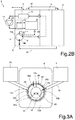
- the thermostatic valve 14 comprises a valve body 30 wherein a first chamber 32a, intended to receive "hot” electrolytic fluid, i.e. at a higher temperature, and a second chamber 32b, intended to receive "cold” electrolytic fluid, i.e. at a lower temperature are defined.
- the first and the second chambers 32a, 32b are separated from each other and are not in fluidic communication; in the example shown, the valve body 30 has a substantially cylinder conformation and the first and second chamber 32a, 32b are defined in a first and in a second half of such valve body 30, separated by a septum.
- the first and the second chamber 32a, 32b have a respective outlet opening 33a, 33b, having, in the illustrated example, in section, a portion-of-arc conformation; such outlet openings 33a, 33b lead into the fluid outlet 15 of the thermostatic valve 14 and are choked by a moving shutter 34, controllable in rotation in order to vary the "outlet port" (i.e. the orifice in fluidic communication with the fluid outlet 15) of the aforesaid outlet openings 33a, 33b and, consequently, the quantity of "hot” electrolytic fluid and "cold” electrolytic fluid that are mixed.
- the moving shutter 34 represents in this embodiment the actuator 19 (or part of such actuator 19) controllable by the electronic control module 18 to adjust the outlet fluid temperature.
- the first chamber 32a has an inlet opening 35a that can be selectively and alternatively fluidically connected to the first mixing inlet 14a of the thermostatic valve 14 and to the first tank 6 (in the normal operating condition, shown in Figure 3A ), or to the third mixing inlet 14c of the thermostatic valve 14 and to the auxiliary tank 20 (in the transition operating condition, shown in Figure 3B ).
- the second chamber 32b has, in turn, an inlet opening 35b that can be selectively and alternatively fluidically connected to the first mixing inlet 14a of the thermostatic valve 14 and to the first tank 6 (in the transition operating condition, shown in Figure 3B ) or to the second mixing inlet 14b of the thermostatic valve 14 and to the second tank 8 (in the normal operating condition, shown in Figure 3A ).
- the thermostatic valve 14 has to this end a moving selector 38, having in the example an arc-shaped conformation at an outer portion of the body 30 of the same thermostatic valve 14, defining a first and a second arc-shaped portion 38', 38", integral between each other, which is movable rotating between a first position and a second position (for example, upon control of the electronic control module 18, by the control signal S c ).
- the first arc-shaped portion 38' closes the inlet to the first chamber 32a from the auxiliary tank 20 (blocking communication between the inlet opening 35a and the third mixing inlet 14c) and at the same time opens the inlet to the first chamber 32a from the first tank 6 (opening communication between the inlet opening 35a and the first mixing inlet 14a); and furthermore, jointly, the second arc-shaped portion 38" closes the inlet to the second chamber 32b from the first tank 6 (blocking communication between the inlet opening 35b and the first mixing inlet 14a) and at the same time opens the inlet to the second chamber 32b from the second tank 8 (opening communication between the inlet opening 35b and the second mixing inlet 14b).
- the first arc-shaped portion 38' rotates to open the inlet to the first chamber 32a from the auxiliary tank 20 (opening communication between the inlet opening 35a and the third mixing inlet 14c) and at a same time closing the inlet to the first chamber 32a from the first tank 6 (blocking communication between the inlet opening 35a and the first mixing inlet 14a); and, furthermore, the second arc-shaped portion 38" rotates (integrally with the aforesaid first arc-shaped portion 38') to open the inlet to the second chamber 32b from the first tank 6 (enabling communication between the inlet opening 35b and the first mixing inlet 14a) and at the same time closes the inlet to the second chamber 32b from the second tank 8 (blocking communication between the inlet opening 35b and the second mixing inlet 14b).
- the first mixing inlet 14a of the thermostatic valve 14 is shared by both chambers 32a, 32b, alternatively and depending on the operating mode; the second mixing inlet 14b is coupled only to the second chamber 32b; and the third mixing inlet 14c is coupled only to the first chamber 32a.
- the moving selector 38 is configured so as to open, in each of the operating conditions, only two inlets, one towards the first chamber 32a and the other towards the second chamber 32b.
- the described solution improves efficiency of the electrochemical power supply source 3, increasing duration thereof and consequently the operating distance of the relative underwater vehicle 1 (for example the launching distance in case of missions wherein the low-speed phase is the most important part, i.e. high-distance launches); in a corresponding manner, the distance being equal, the present solution allows to save energy to be spent at the final phase of the mission (target attack, in case of a torpedo), to be generally performed at high speed.
- the present solution can be advantageously employed in an underwater vehicle 1, in the example a torpedo, having a propulsion system 40 supplied by the electrochemical power supply source 3, which is housed in chamber 2 of the central section of the torpedo tubular body.
- torpedoes are generally designed to be able to perform rapid accelerations, reaching high speeds, while they are not optimized for low speeds (which are in any case associated to high-power consumption) .
- the proposed solution allows, by contrast, to provide the torpedo with two “gears” (an “eco-drive gear” and a “sport-drive gear”), both of them optimized.
- the torpedo in fact starts in “eco-drive gear” and keeps that until the mission requires it; thanks to the possibility of reducing the temperature in normal operating condition, the torpedo proceeds at a low speed with a limited energy consumption.
- the attack step is required, the torpedo can switch to the "sport-drive gear” (in a few seconds), reaching high speeds (thus having a higher residual energy of the corresponding power supply source).
Landscapes
- Engineering & Computer Science (AREA)
- Chemical & Material Sciences (AREA)
- Chemical Kinetics & Catalysis (AREA)
- Electrochemistry (AREA)
- General Chemical & Material Sciences (AREA)
- Manufacturing & Machinery (AREA)
- Physics & Mathematics (AREA)
- General Physics & Mathematics (AREA)
- Automation & Control Theory (AREA)
- Mechanical Engineering (AREA)
- Aviation & Aerospace Engineering (AREA)
- Electrolytic Production Of Non-Metals, Compounds, Apparatuses Therefor (AREA)
Claims (15)
- Eine elektrochemische Leistungsversorgung (3) zur Verwendung in maritimer Umgebung, aufweisend:einen elektrochemischen Stapel (4), der konfiguriert ist zum Erzeugen elektrischer Leistung in Gegenwart eines elektrolytischen Fluids im Inneren,einen ersten Tank (6), der konfiguriert ist zum Halten von elektrolytischem Fluid bei einer ersten Temperatur;einen zweiten Tank (8), der konfiguriert ist zum Halten von elektrolytischem Fluid bei einer zweiten Temperatur, die niedriger ist als die erste,ein Thermostatventil (14), das konfiguriert ist zum Mischen von elektrolytischem Fluid mit der niedrigeren Temperatur mit elektrolytischem Fluid mit einer höheren Temperatur, um ein gemischtes elektrolytisches Fluid zu erzeugen, das in den elektrochemischen Stapel (4) mit einer gesteuerten Temperatur zur Erzeugung einer gewünschten elektrischen Leistung eingeleitet wird,wobei die elektrochemische Leistungsversorgungquelle (3) ferner einen Zusatztank (20) aufweist, der konfiguriert ist zum Halten von elektrolytischem Fluid bei einer dritten Temperatur, die höher ist als die erste Temperatur; wobei das Thermostatventil (14) konfiguriert ist zur Verbindung mit dem Zusatztank (20) und zum Empfangen, an einem Eingang, des elektrolytischen Fluids mit der dritten Temperatur als das elektrolytische Fluid bei mit einer höheren Temperatur, um das gemischte elektrolytische Fluid in einem gegebenen Betriebszustand zu erzeugen.
- Leistungsversorgungsquelle nach Anspruch 1, wobei das Thermostatventil (14) Folgendes aufweist: einen Fluidauslass (15), der mit dem elektrochemischen Stapel (4) verbunden und konfiguriert ist zum Vorsehen des gemischten elektrolytischen Fluids; einen ersten Mischeingang (14a), der fluidisch mit dem ersten Tank (6) verbunden ist, um das elektrolytische Fluid mit der ersten Temperatur aufzunehmen; einen zweiten Mischeingang (14b), der fluidisch mit dem zweiten Tank (8) verbunden ist, um das elektrolytische Fluid mit der zweiten Temperatur aufzunehmen; und einen dritten Mischeingang (14c), der fluidisch mit dem Zusatztank (20) verbunden ist, um das elektrolytische Fluid bei der dritten Temperatur aufzunehmen; wobei das thermostatische Ventil (14) konfiguriert ist zum Umschalten der Mischeinlässe (14a-14c) zwischen:einem normalen Betriebszustand, bei dem das Thermostatventil (14) konfiguriert ist zum Mischen des elektrolytischen Fluids mit der ersten Temperatur, das vom ersten Mischeingang (14a) aufgenommen wird, als das Fluid mit einer höheren Temperatur, mit dem elektrolytischen Fluid mit der zweiten Temperatur, das vom zweiten Mischeingang (14b) aufgenommen wird, als das Fluid mit einer niedrigeren Temperatur;einem Übergangsbetriebszustand, der dem gegebenen Betriebszustand entspricht, bei dem das Thermostatventil (14) konfiguriert ist zum Mischen des elektrolytischen Fluids mit der ersten Temperatur, das von dem ersten Mischeinlass (14a) aufgenommen wird, als das Fluid mit einer niedrigeren Temperatur, mit dem elektrolytischen Fluid mit der dritten Temperatur, das von dem dritten Mischeinlass (14c) aufgenommen wird, als das Fluid mit einer höheren Temperatur.
- Leistungsversorgungsquelle nach Anspruch 2, wobei der Übergangsbetriebszustand ein Zustand hoher Leistungserzeugung durch die Leistungsversorgungsquelle (3) ist, bei dem das Thermostatventil (14) konfiguriert ist zum direkten Einleiten in den elektrochemischen Stapel (4) eines gemischten elektrolytischen Fluids mit hoher Temperatur, als Ergebnis der Vermischung zwischen den Fluiden mit der ersten und dritten Temperatur.
- Leistungsversorgungsquelle nach Anspruch 3, wobei der normale Betriebszustand für das Thermostatventil (14) Folgendem entspricht: einem Zustand niedriger Leistungserzeugung durch die Leistungsversorgungsquelle (3), vor dem Übergangsbetriebszustand; und einem Zustand hoher Leistungserzeugung durch die Leistungsversorgungsquelle (3), nachdem der Übergangsbetriebszustand beendet ist.
- Leistungsversorgungsquelle nach einem der Ansprüche 2 bis 4, ferner aufweisend ein elektronisches Steuermodul (18), das funktionell mit dem Thermostatventil (14) gekoppelt und konfiguriert ist zum Vorsehen eines Steuersignals (Sc), um die Mischeingänge (14a-14c) zu schalten und in geeigneter Weise zu drosseln und eine gewünschte Regulierung der Temperatur des gemischten elektrolytischen Fluids an dem Fluidauslass (15) zu erhalten.
- Leistungsversorgungsquelle nach einem der Ansprüche 2 bis 5, wobei das Thermostatventil (14) folgendes aufweist: einen Ventilkörper (30), in dem eine erste Kammer (32a) definiert ist, die dafür ausgelegt ist, das elektrolytische Fluid mit einer höheren Temperatur aufzunehmen, und in dem eine zweite Kammer (32b) definiert ist, die dafür ausgelegt ist, das elektrolytische Fluid mit einer niedrigeren Temperatur aufzunehmen, wobei die erste und die zweite Kammer (32a, 32b) eine jeweilige Auslassöffnung (33a, 33b) aufweisen, die in den Fluidauslass (15) führt; und ein Einstellbetätigungselement (34), das betätigbar ist zum Variieren der Zumessöffnungen der Auslassöffnungen (33a, 33b) und damit der Mengen des elektrolytischen Fluids mit einer höheren Temperatur und des elektrolytischen Fluids mit einer niedrigeren Temperatur, die gemischt werden, um das gemischte elektrolytische Fluid an dem Fluidauslass (15) zu erzeugen.
- Leistungsversorgungsquelle nach Anspruch 6, wobei die erste Kammer (32a) eine Einlassöffnung (35a) aufweist, die selektiv und alternativ fluidisch mit dem ersten Mischeingang (14a) und mit dem ersten Tank (6), in dem normalen Betriebszustand, oder mit dem dritten Mischeinlass (14c) und mit dem Zusatztank (20) in dem Übergangsbetriebszustand verbindbar ist; und wobei die zweite Kammer (32b) eine entsprechende Einlassöffnung (35b) aufweist, die selektiv und alternativ fluidisch mit dem ersten Mischeinlass (14a) und mit dem ersten Tank (6), in dem Übergangsbetriebszustand, oder mit dem zweiten Mischeinlass (14b) und mit dem zweiten Tank (8), in dem normalen Betriebszustand, verbindbar ist.
- Leistungsversorgungsquelle nach Anspruch 7, wobei das Thermostatventil (14) ferner einen beweglichen Selektor (38) aufweist, der einen ersten und einen zweiten Abschnitt (38', 38") definiert, die einstückig miteinander ausgebildet sind und der zwischen einer ersten Position und einer zweiten Position drehbar ist; wobei in der ersten Position, die dem normalen Betriebszustand entspricht, der erste Abschnitt (38') den Einlass zu der ersten Kammer (32a) von dem Zusatztank (20) schließt und gleichzeitig den Einlass zu der ersten Kammer (32a) von dem ersten Tank (6) öffnet, und ferner der zweite Abschnitt (38") den Einlass zu der zweiten Kammer (32b) von dem ersten Tank (6) schließt und gleichzeitig den Einlass zu der zweiten Kammer (32b) von dem zweiten Tank (8) öffnet; und in der zweiten Position, die dem Übergangsbetriebszustand entspricht, der erste Abschnitt (38') den Einlass zu der ersten Kammer (32a) von dem Zusatztank (20) öffnet und gleichzeitig den Einlass zu der ersten Kammer (32a) von dem ersten Tank (6) schließt, und ferner der zweite Abschnitt (38") den Einlass zu der zweiten Kammer (32b) von dem ersten Tank (6) öffnet und gleichzeitig den Einlass zu der zweiten Kammer (32b) von dem zweiten Tank (8) schließt.
- Leistungsversorgungsquelle nach einem der Ansprüche 2 bis 8, wobei das Thermostatventil (14) im Inneren des ersten Tanks (6) untergebracht ist; der erste Mischeinlass (14a) durch eine Öffnung in direkter Fluidverbindung mit dem ersten Tank (6) gebildet wird; und der zweite Einlass (14b) mit dem zweiten Tank (8) durch eine Verbindungsleitung (16) verbunden ist; ferner aufweisend einen Wärmetauscher (12), der fluidisch den ersten Tank (6) und den zweiten Tank (8) verbindet und der aus dem ersten Tank (6) abgezogenes elektrolytisches Fluid kühlt, das in den zweiten Tank (8) eingeleitet wird.
- Leistungsversorgungsquelle nach einem der Ansprüche 2 bis 9, ferner ausweisend: einen Fluid-Gas-Separator (10) mit einem Einlass, der elektrolytisches Fluid aufnimmt, das aus dem Inneren des elektrochemischen Stapels (4) abgezogen wird, und einem Auslass für den Abfluss von Flüssigkeit, die vom Reaktionsgas getrennt wurde; und eine Pumpe (11), die mit dem Separator (10) gekoppelt ist und die konfiguriert ist zum Zurückführen der Flüssigkeit in den ersten Tank (6); ferner aufweisend ein hydraulisches Umlenkelement (22), das mit der Pumpe (11) gekoppelt ist und das und betreibbar ist zum: Lenken der gesamten Flüssigkeit von der Pumpe (11) zu dem ersten Tank (6) in dem normalen Betriebszustand, und; Umleiten der Flüssigkeit von der Pumpe (11) teilweise zu dem Zusatztank (20) in dem Übergangsbetriebszustand.
- Leistungsversorgungsquelle nach einem der Ansprüche 2 bis 10, ferner aufweisend ein Ventilelement (23), das zwischen dem dritten Mischeingang (14c) und der Innenseite des Zusatztanks (20) angeordnet ist und das während des Übergangsbetriebszustands in einer offenen Konfiguration und während des normalen Betriebszustands in einer geschlossenen Konfiguration konfiguriert werden kann.
- Leistungsversorgungsquelle nach einem der vorhergehenden Ansprüche, wobei der Zusatztank (20) im Inneren des ersten Tanks (6) untergebracht ist und kleinere Abmessungen als der erste Tank (6) aufweist; wobei der Zusatztank (20) ein eigenes wasserdichtes Gehäuse aufweist, das in das in dem ersten Tank (6) enthaltene elektrolytische Fluid eingetaucht ist und das ein hochkonzentriertes elektrolytisches Gemisch enthält, das so ausgelegt ist, dass es das elektrolytische Fluid mit der dritten Temperatur erzeugt, wenn es mit einer Flüssigkeit durchströmt wird.
- Unterwasserfahrzeug (1), aufweisend die elektrochemische Leistungsversorgungsquelle (3) nach einem der vorhergehenden Ansprüche.
- Fahrzeug nach Anspruch 13, aufweisend einen rohrförmigen Körper mit einer Längserstreckungsachse (A), der einen zentralen Abschnitt aufweist, in dem eine Kammer (2) definiert ist, die die elektrochemische Leistungsversorgungsquelle (3) aufnimmt.
- Fahrzeug nach Anspruch 13 oder 14, wobei das Fahrzeug ein Torpedo ist und ein Antriebssystem (40) aufweist; wobei die elektrochemische Leistungsversorgungsquelle (3) so konfiguriert ist, dass sie dem Antriebssystem (40) elektrische Leistung zuführt.
Applications Claiming Priority (1)
| Application Number | Priority Date | Filing Date | Title |
|---|---|---|---|
| IT102019000003821A IT201900003821A1 (it) | 2019-03-15 | 2019-03-15 | Sorgente di alimentazione elettrochimica ad elevata efficienza per un mezzo navale subacqueo |
Publications (2)
| Publication Number | Publication Date |
|---|---|
| EP3709394A1 EP3709394A1 (de) | 2020-09-16 |
| EP3709394B1 true EP3709394B1 (de) | 2021-09-22 |
Family
ID=67002154
Family Applications (1)
| Application Number | Title | Priority Date | Filing Date |
|---|---|---|---|
| EP20162922.7A Active EP3709394B1 (de) | 2019-03-15 | 2020-03-13 | Hocheffiziente elektrochemische stromversorgungsquelle für ein unterwasserfahrzeug |
Country Status (3)
| Country | Link |
|---|---|
| US (1) | US11329353B2 (de) |
| EP (1) | EP3709394B1 (de) |
| IT (1) | IT201900003821A1 (de) |
Family Cites Families (8)
| Publication number | Priority date | Publication date | Assignee | Title |
|---|---|---|---|---|
| CH576878A5 (de) * | 1973-10-08 | 1976-06-30 | Varta Batterie | |
| US4435487A (en) * | 1982-12-13 | 1984-03-06 | Gould Inc. | Primary battery system |
| FR2605804B1 (fr) * | 1986-10-23 | 1989-05-05 | Accumulateurs Fixes | Pile amorcable |
| FR2608322B1 (fr) * | 1986-12-10 | 1989-02-10 | Accumulateurs Fixes | Pile amorcable |
| EP0476916A1 (de) | 1990-09-13 | 1992-03-25 | Westinghouse Electric Corporation | Aluminum-Silberoxid Batteriesystem |
| US5543243A (en) * | 1993-12-01 | 1996-08-06 | Trojan Battery Company | Battery electrolyte circulation system |
| ITVI20030099A1 (it) * | 2003-05-16 | 2004-11-17 | Franco Stocchiero | Metodo per la formazione di batterie al piombo -acido ed |
| US9450227B2 (en) * | 2014-11-07 | 2016-09-20 | Whitehead Sistemi Subacqueri S.P.A. | Thermostatic valve for an electrochemical power source for use in a marine environment |
-
2019
- 2019-03-15 IT IT102019000003821A patent/IT201900003821A1/it unknown
-
2020
- 2020-03-13 EP EP20162922.7A patent/EP3709394B1/de active Active
- 2020-03-13 US US16/818,307 patent/US11329353B2/en active Active
Also Published As
| Publication number | Publication date |
|---|---|
| EP3709394A1 (de) | 2020-09-16 |
| US11329353B2 (en) | 2022-05-10 |
| IT201900003821A1 (it) | 2020-09-15 |
| US20200295342A1 (en) | 2020-09-17 |
Similar Documents
| Publication | Publication Date | Title |
|---|---|---|
| EP1291949B1 (de) | Brennstoffzellensystem, Verfahren zu ihrer Steuerung und damit ausgestattetes Fahrzeug | |
| JP4944300B2 (ja) | 燃料電池システム | |
| RU2552380C2 (ru) | Устройство для производства электроэнергии для подводной лодки, содержащее топливный элемент | |
| EP2975683B1 (de) | Wärmerückgewinnung und temperaturregelung für unterwasserfahrzeuge mit verwendung von brennstoffzellen | |
| US10608263B2 (en) | Coolant bypass structure | |
| FI128599B (en) | Fuel cell systems and procedures as well as equipment for starting fuel cells | |
| EP3605688B1 (de) | Brennstoffzelle und temperatureinstellverfahren | |
| EP3709394B1 (de) | Hocheffiziente elektrochemische stromversorgungsquelle für ein unterwasserfahrzeug | |
| EP1711976B1 (de) | Verfahren zum kaltstart eines brennstoffzellensystems bei temperaturen unter null | |
| JP2019114352A (ja) | 燃料電池システム及びその制御方法 | |
| US8137834B2 (en) | Propulsion cell for a device in an aquatic medium | |
| US20180248206A1 (en) | Cooling system for a fuel cell, and a fuel cell system | |
| CN109346746A (zh) | 一种密闭空间用燃料电池的供氧装置以及供氧方法 | |
| CN106207225A (zh) | 车辆燃料电池的离子过滤器顶部结构 | |
| KR101785462B1 (ko) | 잠수함용 고압형 수증기 연료개질기 시동 및 운전 방법 및 연료개질 시스템 | |
| KR20170014295A (ko) | 무인항공기용 동력공급장치 및 그 제어방법 | |
| US20220320549A1 (en) | Operating method of fuel cell system | |
| EP3709395B1 (de) | Ventilsystem für eine elektrochemische energiequelle, insbesondere für ein unterwasserfahrzeug, und dessen elektrochemische energiequelle | |
| US20140205925A1 (en) | Fuel Cell System | |
| EP1836742B1 (de) | Passiver mikrokühlmittelkreis für eine elektrochemische brennstoffzelle | |
| US10020521B2 (en) | Fuel cell cogeneration system, method of starting operation of the fuel cell cogeneration system, and method of operating the fuel cell cogeneration system | |
| US20250042729A1 (en) | A Method for Producing Hydrogen Containing Gas | |
| US7056609B2 (en) | System and method for starting a fuel cell stack assembly at sub-freezing temperature | |
| US3498845A (en) | Galvanic battery | |
| JP2012156039A (ja) | 燃料電池システム |
Legal Events
| Date | Code | Title | Description |
|---|---|---|---|
| PUAI | Public reference made under article 153(3) epc to a published international application that has entered the european phase |
Free format text: ORIGINAL CODE: 0009012 |
|
| STAA | Information on the status of an ep patent application or granted ep patent |
Free format text: STATUS: THE APPLICATION HAS BEEN PUBLISHED |
|
| AK | Designated contracting states |
Kind code of ref document: A1 Designated state(s): AL AT BE BG CH CY CZ DE DK EE ES FI FR GB GR HR HU IE IS IT LI LT LU LV MC MK MT NL NO PL PT RO RS SE SI SK SM TR |
|
| AX | Request for extension of the european patent |
Extension state: BA ME |
|
| STAA | Information on the status of an ep patent application or granted ep patent |
Free format text: STATUS: REQUEST FOR EXAMINATION WAS MADE |
|
| 17P | Request for examination filed |
Effective date: 20210216 |
|
| RBV | Designated contracting states (corrected) |
Designated state(s): AL AT BE BG CH CY CZ DE DK EE ES FI FR GB GR HR HU IE IS IT LI LT LU LV MC MK MT NL NO PL PT RO RS SE SI SK SM TR |
|
| REG | Reference to a national code |
Ref country code: DE Ref legal event code: R079 Ref document number: 602020000577 Country of ref document: DE Free format text: PREVIOUS MAIN CLASS: H01M0002400000 Ipc: H01M0006040000 |
|
| GRAP | Despatch of communication of intention to grant a patent |
Free format text: ORIGINAL CODE: EPIDOSNIGR1 |
|
| STAA | Information on the status of an ep patent application or granted ep patent |
Free format text: STATUS: GRANT OF PATENT IS INTENDED |
|
| RIC1 | Information provided on ipc code assigned before grant |
Ipc: H01M 50/77 20210101ALN20210325BHEP Ipc: H01M 6/50 20060101ALI20210325BHEP Ipc: H01M 6/34 20060101ALI20210325BHEP Ipc: H01M 6/04 20060101AFI20210325BHEP |
|
| INTG | Intention to grant announced |
Effective date: 20210416 |
|
| GRAS | Grant fee paid |
Free format text: ORIGINAL CODE: EPIDOSNIGR3 |
|
| GRAA | (expected) grant |
Free format text: ORIGINAL CODE: 0009210 |
|
| STAA | Information on the status of an ep patent application or granted ep patent |
Free format text: STATUS: THE PATENT HAS BEEN GRANTED |
|
| AK | Designated contracting states |
Kind code of ref document: B1 Designated state(s): AL AT BE BG CH CY CZ DE DK EE ES FI FR GB GR HR HU IE IS IT LI LT LU LV MC MK MT NL NO PL PT RO RS SE SI SK SM TR |
|
| RAP3 | Party data changed (applicant data changed or rights of an application transferred) |
Owner name: LEONARDO S.P.A. |
|
| REG | Reference to a national code |
Ref country code: GB Ref legal event code: FG4D |
|
| REG | Reference to a national code |
Ref country code: IE Ref legal event code: FG4D |
|
| REG | Reference to a national code |
Ref country code: DE Ref legal event code: R096 Ref document number: 602020000577 Country of ref document: DE |
|
| REG | Reference to a national code |
Ref country code: CH Ref legal event code: EP Ref country code: AT Ref legal event code: REF Ref document number: 1433005 Country of ref document: AT Kind code of ref document: T Effective date: 20211015 |
|
| REG | Reference to a national code |
Ref country code: LT Ref legal event code: MG9D |
|
| REG | Reference to a national code |
Ref country code: NL Ref legal event code: MP Effective date: 20210922 |
|
| PG25 | Lapsed in a contracting state [announced via postgrant information from national office to epo] |
Ref country code: HR Free format text: LAPSE BECAUSE OF FAILURE TO SUBMIT A TRANSLATION OF THE DESCRIPTION OR TO PAY THE FEE WITHIN THE PRESCRIBED TIME-LIMIT Effective date: 20210922 Ref country code: FI Free format text: LAPSE BECAUSE OF FAILURE TO SUBMIT A TRANSLATION OF THE DESCRIPTION OR TO PAY THE FEE WITHIN THE PRESCRIBED TIME-LIMIT Effective date: 20210922 Ref country code: NO Free format text: LAPSE BECAUSE OF FAILURE TO SUBMIT A TRANSLATION OF THE DESCRIPTION OR TO PAY THE FEE WITHIN THE PRESCRIBED TIME-LIMIT Effective date: 20211222 Ref country code: BG Free format text: LAPSE BECAUSE OF FAILURE TO SUBMIT A TRANSLATION OF THE DESCRIPTION OR TO PAY THE FEE WITHIN THE PRESCRIBED TIME-LIMIT Effective date: 20211222 Ref country code: LT Free format text: LAPSE BECAUSE OF FAILURE TO SUBMIT A TRANSLATION OF THE DESCRIPTION OR TO PAY THE FEE WITHIN THE PRESCRIBED TIME-LIMIT Effective date: 20210922 Ref country code: RS Free format text: LAPSE BECAUSE OF FAILURE TO SUBMIT A TRANSLATION OF THE DESCRIPTION OR TO PAY THE FEE WITHIN THE PRESCRIBED TIME-LIMIT Effective date: 20210922 Ref country code: SE Free format text: LAPSE BECAUSE OF FAILURE TO SUBMIT A TRANSLATION OF THE DESCRIPTION OR TO PAY THE FEE WITHIN THE PRESCRIBED TIME-LIMIT Effective date: 20210922 |
|
| REG | Reference to a national code |
Ref country code: AT Ref legal event code: MK05 Ref document number: 1433005 Country of ref document: AT Kind code of ref document: T Effective date: 20210922 |
|
| PG25 | Lapsed in a contracting state [announced via postgrant information from national office to epo] |
Ref country code: LV Free format text: LAPSE BECAUSE OF FAILURE TO SUBMIT A TRANSLATION OF THE DESCRIPTION OR TO PAY THE FEE WITHIN THE PRESCRIBED TIME-LIMIT Effective date: 20210922 Ref country code: GR Free format text: LAPSE BECAUSE OF FAILURE TO SUBMIT A TRANSLATION OF THE DESCRIPTION OR TO PAY THE FEE WITHIN THE PRESCRIBED TIME-LIMIT Effective date: 20211223 |
|
| PG25 | Lapsed in a contracting state [announced via postgrant information from national office to epo] |
Ref country code: AT Free format text: LAPSE BECAUSE OF FAILURE TO SUBMIT A TRANSLATION OF THE DESCRIPTION OR TO PAY THE FEE WITHIN THE PRESCRIBED TIME-LIMIT Effective date: 20210922 |
|
| PG25 | Lapsed in a contracting state [announced via postgrant information from national office to epo] |
Ref country code: IS Free format text: LAPSE BECAUSE OF FAILURE TO SUBMIT A TRANSLATION OF THE DESCRIPTION OR TO PAY THE FEE WITHIN THE PRESCRIBED TIME-LIMIT Effective date: 20220122 Ref country code: SK Free format text: LAPSE BECAUSE OF FAILURE TO SUBMIT A TRANSLATION OF THE DESCRIPTION OR TO PAY THE FEE WITHIN THE PRESCRIBED TIME-LIMIT Effective date: 20210922 Ref country code: RO Free format text: LAPSE BECAUSE OF FAILURE TO SUBMIT A TRANSLATION OF THE DESCRIPTION OR TO PAY THE FEE WITHIN THE PRESCRIBED TIME-LIMIT Effective date: 20210922 Ref country code: PT Free format text: LAPSE BECAUSE OF FAILURE TO SUBMIT A TRANSLATION OF THE DESCRIPTION OR TO PAY THE FEE WITHIN THE PRESCRIBED TIME-LIMIT Effective date: 20220124 Ref country code: PL Free format text: LAPSE BECAUSE OF FAILURE TO SUBMIT A TRANSLATION OF THE DESCRIPTION OR TO PAY THE FEE WITHIN THE PRESCRIBED TIME-LIMIT Effective date: 20210922 Ref country code: NL Free format text: LAPSE BECAUSE OF FAILURE TO SUBMIT A TRANSLATION OF THE DESCRIPTION OR TO PAY THE FEE WITHIN THE PRESCRIBED TIME-LIMIT Effective date: 20210922 Ref country code: ES Free format text: LAPSE BECAUSE OF FAILURE TO SUBMIT A TRANSLATION OF THE DESCRIPTION OR TO PAY THE FEE WITHIN THE PRESCRIBED TIME-LIMIT Effective date: 20210922 Ref country code: EE Free format text: LAPSE BECAUSE OF FAILURE TO SUBMIT A TRANSLATION OF THE DESCRIPTION OR TO PAY THE FEE WITHIN THE PRESCRIBED TIME-LIMIT Effective date: 20210922 Ref country code: CZ Free format text: LAPSE BECAUSE OF FAILURE TO SUBMIT A TRANSLATION OF THE DESCRIPTION OR TO PAY THE FEE WITHIN THE PRESCRIBED TIME-LIMIT Effective date: 20210922 Ref country code: AL Free format text: LAPSE BECAUSE OF FAILURE TO SUBMIT A TRANSLATION OF THE DESCRIPTION OR TO PAY THE FEE WITHIN THE PRESCRIBED TIME-LIMIT Effective date: 20210922 |
|
| REG | Reference to a national code |
Ref country code: DE Ref legal event code: R097 Ref document number: 602020000577 Country of ref document: DE |
|
| PG25 | Lapsed in a contracting state [announced via postgrant information from national office to epo] |
Ref country code: DK Free format text: LAPSE BECAUSE OF FAILURE TO SUBMIT A TRANSLATION OF THE DESCRIPTION OR TO PAY THE FEE WITHIN THE PRESCRIBED TIME-LIMIT Effective date: 20210922 |
|
| PLBE | No opposition filed within time limit |
Free format text: ORIGINAL CODE: 0009261 |
|
| STAA | Information on the status of an ep patent application or granted ep patent |
Free format text: STATUS: NO OPPOSITION FILED WITHIN TIME LIMIT |
|
| 26N | No opposition filed |
Effective date: 20220623 |
|
| PG25 | Lapsed in a contracting state [announced via postgrant information from national office to epo] |
Ref country code: MC Free format text: LAPSE BECAUSE OF FAILURE TO SUBMIT A TRANSLATION OF THE DESCRIPTION OR TO PAY THE FEE WITHIN THE PRESCRIBED TIME-LIMIT Effective date: 20210922 |
|
| PG25 | Lapsed in a contracting state [announced via postgrant information from national office to epo] |
Ref country code: SI Free format text: LAPSE BECAUSE OF FAILURE TO SUBMIT A TRANSLATION OF THE DESCRIPTION OR TO PAY THE FEE WITHIN THE PRESCRIBED TIME-LIMIT Effective date: 20210922 |
|
| REG | Reference to a national code |
Ref country code: BE Ref legal event code: MM Effective date: 20220331 |
|
| PG25 | Lapsed in a contracting state [announced via postgrant information from national office to epo] |
Ref country code: LU Free format text: LAPSE BECAUSE OF NON-PAYMENT OF DUE FEES Effective date: 20220313 Ref country code: IT Free format text: LAPSE BECAUSE OF FAILURE TO SUBMIT A TRANSLATION OF THE DESCRIPTION OR TO PAY THE FEE WITHIN THE PRESCRIBED TIME-LIMIT Effective date: 20210922 Ref country code: IE Free format text: LAPSE BECAUSE OF NON-PAYMENT OF DUE FEES Effective date: 20220313 |
|
| PG25 | Lapsed in a contracting state [announced via postgrant information from national office to epo] |
Ref country code: BE Free format text: LAPSE BECAUSE OF NON-PAYMENT OF DUE FEES Effective date: 20220331 |
|
| REG | Reference to a national code |
Ref country code: CH Ref legal event code: PL |
|
| PG25 | Lapsed in a contracting state [announced via postgrant information from national office to epo] |
Ref country code: LI Free format text: LAPSE BECAUSE OF NON-PAYMENT OF DUE FEES Effective date: 20230331 Ref country code: CH Free format text: LAPSE BECAUSE OF NON-PAYMENT OF DUE FEES Effective date: 20230331 |
|
| PG25 | Lapsed in a contracting state [announced via postgrant information from national office to epo] |
Ref country code: SM Free format text: LAPSE BECAUSE OF FAILURE TO SUBMIT A TRANSLATION OF THE DESCRIPTION OR TO PAY THE FEE WITHIN THE PRESCRIBED TIME-LIMIT Effective date: 20210922 Ref country code: MK Free format text: LAPSE BECAUSE OF FAILURE TO SUBMIT A TRANSLATION OF THE DESCRIPTION OR TO PAY THE FEE WITHIN THE PRESCRIBED TIME-LIMIT Effective date: 20210922 Ref country code: CY Free format text: LAPSE BECAUSE OF FAILURE TO SUBMIT A TRANSLATION OF THE DESCRIPTION OR TO PAY THE FEE WITHIN THE PRESCRIBED TIME-LIMIT Effective date: 20210922 |
|
| PG25 | Lapsed in a contracting state [announced via postgrant information from national office to epo] |
Ref country code: HU Free format text: LAPSE BECAUSE OF FAILURE TO SUBMIT A TRANSLATION OF THE DESCRIPTION OR TO PAY THE FEE WITHIN THE PRESCRIBED TIME-LIMIT; INVALID AB INITIO Effective date: 20200313 |
|
| PG25 | Lapsed in a contracting state [announced via postgrant information from national office to epo] |
Ref country code: MT Free format text: LAPSE BECAUSE OF FAILURE TO SUBMIT A TRANSLATION OF THE DESCRIPTION OR TO PAY THE FEE WITHIN THE PRESCRIBED TIME-LIMIT Effective date: 20210922 |
|
| REG | Reference to a national code |
Ref country code: DE Ref legal event code: R081 Ref document number: 602020000577 Country of ref document: DE Owner name: WASS SUBMARINE SYSTEMS S.R.L., IT Free format text: FORMER OWNER: LEONARDO S.P.A., ROMA, IT |
|
| REG | Reference to a national code |
Ref country code: GB Ref legal event code: 732E Free format text: REGISTERED BETWEEN 20250424 AND 20250430 |
|
| PG25 | Lapsed in a contracting state [announced via postgrant information from national office to epo] |
Ref country code: TR Free format text: LAPSE BECAUSE OF FAILURE TO SUBMIT A TRANSLATION OF THE DESCRIPTION OR TO PAY THE FEE WITHIN THE PRESCRIBED TIME-LIMIT Effective date: 20210922 |
|
| PGFP | Annual fee paid to national office [announced via postgrant information from national office to epo] |
Ref country code: GB Payment date: 20260304 Year of fee payment: 7 |
|
| PGFP | Annual fee paid to national office [announced via postgrant information from national office to epo] |
Ref country code: DE Payment date: 20260320 Year of fee payment: 7 |
|
| PGFP | Annual fee paid to national office [announced via postgrant information from national office to epo] |
Ref country code: FR Payment date: 20260323 Year of fee payment: 7 |