EP3709172A1 - Control-program-development supporting apparatus, control-program-development supporting system, control-program-development supporting method, and control-program-development supporting program - Google Patents
Control-program-development supporting apparatus, control-program-development supporting system, control-program-development supporting method, and control-program-development supporting program Download PDFInfo
- Publication number
- EP3709172A1 EP3709172A1 EP18877182.8A EP18877182A EP3709172A1 EP 3709172 A1 EP3709172 A1 EP 3709172A1 EP 18877182 A EP18877182 A EP 18877182A EP 3709172 A1 EP3709172 A1 EP 3709172A1
- Authority
- EP
- European Patent Office
- Prior art keywords
- program
- control
- debugging
- editing
- variable
- Prior art date
- Legal status (The legal status is an assumption and is not a legal conclusion. Google has not performed a legal analysis and makes no representation as to the accuracy of the status listed.)
- Granted
Links
Images



Classifications
-
- G—PHYSICS
- G06—COMPUTING OR CALCULATING; COUNTING
- G06F—ELECTRIC DIGITAL DATA PROCESSING
- G06F11/00—Error detection; Error correction; Monitoring
- G06F11/36—Prevention of errors by analysis, debugging or testing of software
- G06F11/362—Debugging of software
- G06F11/3624—Debugging of software by performing operations on the source code, e.g. via a compiler
-
- G—PHYSICS
- G06—COMPUTING OR CALCULATING; COUNTING
- G06F—ELECTRIC DIGITAL DATA PROCESSING
- G06F11/00—Error detection; Error correction; Monitoring
- G06F11/36—Prevention of errors by analysis, debugging or testing of software
- G06F11/3698—Environments for analysis, debugging or testing of software
-
- G—PHYSICS
- G06—COMPUTING OR CALCULATING; COUNTING
- G06F—ELECTRIC DIGITAL DATA PROCESSING
- G06F11/00—Error detection; Error correction; Monitoring
- G06F11/30—Monitoring
- G06F11/32—Monitoring with visual or acoustical indication of the functioning of the machine
- G06F11/323—Visualisation of programs or trace data
-
- G—PHYSICS
- G06—COMPUTING OR CALCULATING; COUNTING
- G06F—ELECTRIC DIGITAL DATA PROCESSING
- G06F11/00—Error detection; Error correction; Monitoring
- G06F11/36—Prevention of errors by analysis, debugging or testing of software
- G06F11/362—Debugging of software
-
- G—PHYSICS
- G06—COMPUTING OR CALCULATING; COUNTING
- G06F—ELECTRIC DIGITAL DATA PROCESSING
- G06F11/00—Error detection; Error correction; Monitoring
- G06F11/36—Prevention of errors by analysis, debugging or testing of software
- G06F11/362—Debugging of software
- G06F11/3636—Debugging of software by tracing the execution of the program
-
- G—PHYSICS
- G06—COMPUTING OR CALCULATING; COUNTING
- G06F—ELECTRIC DIGITAL DATA PROCESSING
- G06F11/00—Error detection; Error correction; Monitoring
- G06F11/36—Prevention of errors by analysis, debugging or testing of software
- G06F11/362—Debugging of software
- G06F11/366—Debugging of software using diagnostics
-
- G—PHYSICS
- G06—COMPUTING OR CALCULATING; COUNTING
- G06F—ELECTRIC DIGITAL DATA PROCESSING
- G06F8/00—Arrangements for software engineering
- G06F8/30—Creation or generation of source code
Definitions
- the disclosure relates to a technique of supporting development of a control program.
- An FA system includes a controller and a plurality of slave devices.
- a control program is provided in the controller, and operations and processes of the controller and operations and processes of the slave devices are set by the control program.
- An apparatus that prepares such a control program has a configuration like that described in Patent Literature 1.
- the apparatus that prepares a control program and includes the apparatus described in Patent Literature 1 normally has a debugging function.
- an objective of the disclosure is to more easily identify the cause of an error or the like and to shorten the time for debugging.
- a control-program-development supporting apparatus includes an editing unit and a display unit.
- the editing unit performs editing of a control program and debugging of the control program.
- the display unit displays contents of the editing and contents of the debugging.
- the editing unit displays debugging assistance information including at least one of past editing contents of the program constituent or variable which is to be debugged, change contents of the control program, and relevant error information on the display unit.
- debugging assistance information which is referred to at the time of debugging is simultaneously displayed on a debugging screen.
- the editing unit may display the debugging assistance information associated with the program constituent on the display unit.
- the editing unit may set reception of observation of the designated variable as a process for the variable, and the editing unit may display the debugging assistance information associated with the variable on the display unit when the same variable is set in the reception of observation which has been performed the plurality of times.
- debugging assistance information is displayed on the basis of the processes which are performed in normal debugging, no particular operation need be performed to display the debugging assistance information.
- the editing unit may display a comparison image for a position between the program constituent which is to be debugged and the program constituent which is to be debugged and which is included in the debugging assistance information on the display unit.
- the editing unit may display a comparison image between a parameter of the variable which is to be debugged and a parameter of the variable which is included in the debugging assistance information on the display unit.
- a control-program-development supporting system includes: each configuration of the above-mentioned control-program-development supporting apparatus; and a server that is connected to the control-program-development supporting apparatus.
- the server stores the debugging assistance information.
- the editing unit acquires the past editing contents from the server.
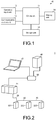
- FIG. 1 is a functional block diagram illustrating a control-program-development supporting apparatus according to an embodiment of the disclosure.
- a control-program-development supporting apparatus 10 includes at least an editing unit 11 and a display unit 14.
- the editing unit 11 performs editing and debugging of a control program.
- the editing unit 11 outputs an editing screen and a debugging screen of the control program to the display unit 14.
- the display unit 14 displays the editing screen and the debugging screen of the control program.
- the editing unit 11 detects the process.
- the editing unit 11 extracts debugging assistance information with detection of the process as a trigger.
- the debugging assistance information is information including at least one of past editing contents of a program constituent or variable which is to be debugged, change contents of the control program, and relevant error information.
- the editing unit 11 outputs the extracted debugging assistance information to the display unit 14.
- the display unit 14 displays the extracted debugging assistance information on the debugging screen to overlap the debugging screen.
- FIG. 1 is a functional block diagram illustrating a control-program-development supporting apparatus according to an embodiment of the disclosure.
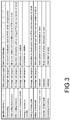
- FIG. 2 is a diagram schematically illustrating a configuration of a control system including a control-program-development supporting system according to an embodiment of the disclosure.
- a control-program-development supporting apparatus 10 includes an editing unit 11, a storage unit 12, an operation input unit 13, a display unit 14, and a communication control unit 15.
- the editing unit 11 is connected to the storage unit 12, the operation input unit 13, the display unit 14, and the communication control unit 15.
- the control-program-development supporting apparatus 10 is realized by an operation processing device such as a personal computer.
- the editing unit 11 is realized by an operation processing device such as a CPU, a program which is executed by the operation processing device, and the like.
- the editing unit 11 performs various processes associated with development of a control program such as editing and debugging of the control program.
- the storage unit 12 is a storage area which is used for the operation processing device to perform various processes and is realized by a predetermined storage medium. Past editing contents which will be described later may be stored by enhancing the capacity of the storage unit 12.
- the operation input unit 13 is realized by, for example, a keyboard and a mouse.
- the operation input unit 13 receives an operation input from an operator such as a programmer and transmits the received operation input to the editing unit 11.
- the display unit 14 is realized by, for example, a liquid crystal display.
- the display unit 14 displays an editing screen of a control program and a debugging screen which are input from the editing unit 11 and information for assisting with debugging (debugging assistance information) such as past editing contents which will be described later.
- the communication control unit 15 is an interface that connects the control-program-development supporting apparatus 10 to an external network.
- the control-program-development supporting apparatus 10 is applied to a control system illustrated in FIG. 2 .
- the control system 1 includes a control-program-development supporting apparatus 10, a controller 21, slave devices 221, 222, and 223, and a server 40.
- the controller 21 is connected to the slave devices 221, 222, and 223 via a control network 30.
- the control network 30 is set, for example, on the basis of Ethernet (registered trademark) or EtherCAT (registered trademark).
- the control-program-development supporting apparatus 10, the controller 21, and the server 40 are connected to each other via an information communication network 50.
- the information communication network 50 is set, for example, on the basis of Ethernet (registered trademark).
- the controller 21 receives a control program from the control-program-development supporting apparatus 10 and stores the received control program.
- the controller 21 controls processes of the host device and operations and processes of the slave devices 221, 222, and 223 in accordance with the control program.
- the server 40 collects assistance information of debugging from the control-program-development supporting apparatus 10 and the controller 21 via the information communication network 50.
- the assistance information of debugging includes, for example, editing contents of a control program which was performed in the past in the control-program-development supporting apparatus 10 and error information of the controller 21 and the slave devices 221, 222, and 223.
- the server 40 may collect the assistance information of debugging directly from the control-program-development supporting apparatus 10 and the controller 21 or may collect the assistance information of debugging via the control-program-development supporting apparatus 10.
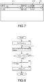
- FIG. 3 is a table illustrating an example of debugging assistance information which is collected by the server.
- the debugging assistance information is classified into items such as operation contents, a data collection source, and data to be collected, which are correlated with each other.
- the operation contents are processes serving as a trigger for collection, and examples thereof include downloading, online editing transmission, an offline editing history, observation of a designated variable, writing of a variable to a controller, setting of a break point, setting of a bookmark, detection of power interruption of a slave, detection of a slight fault, and all-clearing of a memory.
- the data collection source represents a target device in which the operation contents have been performed, and examples thereof include a development program (the control-program-development supporting apparatus 10) and the controller.
- the data to be collected is information serving as a reference for the debugging assistance information and information for assisting with debugging, and examples thereof include program constituents POU, circuits, parameters of variables, row numbers of the POUs, row numbers of the circuits, node numbers of the slaves, and information on errors.
- Such information may be stored in the control-program-development supporting apparatus 10. However, by storing such information in the server 40, it is possible to enhance a storage capacity for information. Accordingly, it is possible to keep an amount of debugging assistance information large and to more reliably and easily provide suitable assistance information.
- FIG. 4 is a flowchart illustrating an example of a process at the time of debugging.
- the editing unit 11 of the control-program-development supporting apparatus 10 receives start of debugging of a control program (S11). Debugging is performed with starting of a simulator or while connected to the controller 21 (in an online state).
- the editing unit 11 receives editing and transmission of a program constituent POU via the operation input unit 13 (S12).
- the editing unit 11 extracts debugging assistance information such as an editing history of the program constituent POU (past editing contents) associated with the program constituent POU at the debugging position from the server 40 (S14). At this time, the editing unit 11 extracts the editing history of the program constituent POU using the data to be edited illustrated in FIG. 3 as a keyword.
- the editing unit 11 generates a list image of the extracted editing history of the program constituent POU and outputs the generated list image to the display unit 14.
- the display unit 14 displays the list image (S15).
- FIG. 5 is a diagram illustrating an example of a display screen at the time of debugging.
- a display screen 140 includes an index 141, a debugging screen 142, and a list of assistance information 143.
- a program which is being debugged is displayed in the index 141.
- a progress state of debugging, program constituents POU of a program which is being debugged, and the like are displayed in the debugging screen 142.
- a list image of the extracted editing history is displayed in the list of assistance information 143.
- An editing date and time Date, an edited program constituent POU, an editor User, and the like are included in the list of assistance information 143.
- the plurality of pieces of assistance information are preferably displayed in a time series. Accordingly, it is possible to easily recognize the newest editing history.
- Arrangement of the plurality of pieces of assistance information is not limited thereto and the plurality of pieces of assistance information may be arranged, for example, on the basis of a degree of coincidence of a keyword. When the degree of coincidence of a keyword is used, it is possible to easily recognize an editing history which is more suitable for this debugging.
- FIG. 6 is a flowchart illustrating an example of a process of displaying a comparison screen.
- the editing unit 11 receives selection of an item in the list of assistance information 143 illustrated in FIG. 5 via the operation input unit 13 (S21).
- FIG. 7 is a diagram illustrating an example of a comparison screen. As illustrated in FIG. 7 , the display screen 140 is partitioned in the horizontal direction, and a display area 411 of the program constituent POU which is being debugged and a display area 412 of the program constituent POU of the selected assistance information are arranged in parallel. Positions that differ in the program constituent POU between the display area 411 and the display area 412 are emphasized and displayed.
- a programmer can visually recognize the program constituent POU which is being debugged and the program constituent POU of the selected assistance information in parallel. Accordingly, a programmer can easily recognize a difference between the program constituent POU which is being debugged and the program constituent POU of the selected assistance information and can easily perform debugging. By emphasizing and displaying the different positions, a programmer can more clearly and easily recognize a difference between the program constituent POU which is being debugged and the program constituent POU of the selected assistance information and can easily perform debugging.
- FIG. 8 is a flowchart illustrating another example of a process at the time of debugging.
- the editing unit 11 of the control-program-development supporting apparatus 10 receives start of debugging of a control program (S31). Debugging is performed with starting of a simulator or while connected to the controller 21 (in an online state).
- the editing unit 11 receives observation of a designated variable via the operation input unit 13 (S32). Specifically, the editing unit 11 sets a watch window and observes a variable which is registered in the watch window.
- the editing unit 11 extracts debugging assistance information such as an editing history of a program constituent POU associated with the variable from the server 40 (S34). At this time, the editing unit 11 extracts the editing history of the program constituent POU using the data to be edited which is illustrated in FIG. 3 as a keyword.
- the editing unit 11 generates a list image of the extracted editing history of the program constituent POU and outputs the list image to the display unit 14. Alternatively, the editing unit 11 generates a list image of a history of the corresponding function in the editing history of the program constituent POU.
- the display unit 14 displays the list images (S35).
- FIG. 9 is a diagram illustrating an example of a display screen at the time of debugging.
- the display screen 140 includes an index 141, a watch window setting field 144, a list of assistance information 143, and a list of assistance information on a variable 145.
- Starting of a watch window is displayed in the index 141.
- a designated variable is displayed in the watch window setting field 144.
- a list image of the editing history which has been extracted as described above is displayed in the list of assistance information 143.
- the list of assistance information 143 includes an editing date and time Date, an edited program constituent POU, and an editor User.
- the list of assistance information on a variable 145 includes an editing date and time Date, a control element of which a variable is to be set (an axis in the example illustrated in FIG. 9 ), and an editor User.
- the pieces of assistance information are preferably displayed in a time series. Accordingly, it is possible to easily recognize a newest editing history.
- FIG. 10 is a flowchart illustrating an example of a process of displaying error information or a comparison screen.
- the editing unit 11 receives selection of an item in the list of assistance information on a variable 145 illustrated in FIG. 9 via the operation input unit 13 (S41).
- the editing unit 11 When there is error information in the selected item (S42: YES), the editing unit 11 generates error information and the display unit 14 displays the error information (S43). When there is no error information in the selected item (S42: NO), the editing unit 11 generates a comparison image and the display unit 14 displays the comparison image.
- a programmer can easily recognize an error associated with a variable which is being debugged and easily perform debugging.
Landscapes
- Engineering & Computer Science (AREA)
- Theoretical Computer Science (AREA)
- General Engineering & Computer Science (AREA)
- Physics & Mathematics (AREA)
- General Physics & Mathematics (AREA)
- Quality & Reliability (AREA)
- Computer Hardware Design (AREA)
- Software Systems (AREA)
- Data Mining & Analysis (AREA)
- Debugging And Monitoring (AREA)
- Stored Programmes (AREA)
Abstract
Description
- The disclosure relates to a technique of supporting development of a control program.
- Currently, factory automation (FA) systems are being widely implemented. An FA system includes a controller and a plurality of slave devices. A control program is provided in the controller, and operations and processes of the controller and operations and processes of the slave devices are set by the control program.
- An apparatus that prepares such a control program has a configuration like that described in
Patent Literature 1. - The apparatus that prepares a control program and includes the apparatus described in
Patent Literature 1 normally has a debugging function. - Japanese Patent Laid-Open No.
2016-200872 - However, when a control program becomes larger in scale, the number of program organization units (POUs) or variables which are to be debugged also increases. In this case, identification of a position causing an error and dependencies between the POUs and the variables are complicated and a time for debugging is lengthened. Particularly, in the case of an error due to a complicated cause, it may be difficult for a programmer who is not well-acquainted with the control program to perform debugging.
- Accordingly, an objective of the disclosure is to more easily identify the cause of an error or the like and to shorten the time for debugging.
- A control-program-development supporting apparatus includes an editing unit and a display unit. The editing unit performs editing of a control program and debugging of the control program. The display unit displays contents of the editing and contents of the debugging. When the same process is designated for a program constituent or variable which is to be debugged and which is included in the control program a plurality of times at the time of debugging, the editing unit displays debugging assistance information including at least one of past editing contents of the program constituent or variable which is to be debugged, change contents of the control program, and relevant error information on the display unit.
- With this configuration, when the same debugging process is performed a plurality of times, debugging assistance information which is referred to at the time of debugging is simultaneously displayed on a debugging screen.
- In the control-program-development supporting apparatus, when the program constituent is edited continuously a plurality of times and is transmitted to a controller as a process for the program constituent, the editing unit may display the debugging assistance information associated with the program constituent on the display unit.
- In the control-program-development supporting apparatus, the editing unit may set reception of observation of the designated variable as a process for the variable, and the editing unit may display the debugging assistance information associated with the variable on the display unit when the same variable is set in the reception of observation which has been performed the plurality of times.
- These configurations represent a process example in which the process of displaying debugging assistance information is triggered. Since the debugging assistance information is displayed on the basis of the processes which are performed in normal debugging, no particular operation need be performed to display the debugging assistance information.
- In the control-program-development supporting apparatus, the editing unit may display a comparison image for a position between the program constituent which is to be debugged and the program constituent which is to be debugged and which is included in the debugging assistance information on the display unit.
- With this configuration, a program constituent which is to be debugged and a program constituent which is to be compared can be easily compared.
- In the control-program-development supporting apparatus, the editing unit may display a comparison image between a parameter of the variable which is to be debugged and a parameter of the variable which is included in the debugging assistance information on the display unit.
- With this configuration, a variable which is to be debugged and a variable which is to be compared can be easily compared.
- A control-program-development supporting system includes: each configuration of the above-mentioned control-program-development supporting apparatus; and a server that is connected to the control-program-development supporting apparatus. The server stores the debugging assistance information. The editing unit acquires the past editing contents from the server.
- With this configuration, since past editing contents are stored in the server, it is possible to enhance a storage capacity. Accordingly, a large amount of information for assisting with debugging can be displayed by the control-program-development supporting apparatus.
- According to the disclosure, it is possible to more easily identify the cause of an error or the like and to shorten the time for debugging.
-
-
FIG. 1 is a functional block diagram illustrating a control-program-development supporting apparatus according to an embodiment of the disclosure. -
FIG. 2 is a diagram schematically illustrating a configuration of a control system including a control-program-development supporting system according to an embodiment of the disclosure. -
FIG. 3 is a table illustrating an example of debugging assistance information which is collected by a server. -
FIG. 4 is a flowchart illustrating an example of a process at the time of debugging. -
FIG. 5 is a diagram illustrating an example of a display screen at the time of debugging. -
FIG. 6 is a flowchart illustrating an example of a process of displaying a comparison screen. -
FIG. 7 is a diagram illustrating an example of a comparison screen. -
FIG. 8 is a flowchart illustrating another example of a process at the time of debugging. -
FIG. 9 is a diagram illustrating an example of a display screen at the time of debugging. -
FIG. 10 is a flowchart illustrating an example of a process of displaying error information or a comparison screen. - (A) of
FIG. 11 is a diagram illustrating an example of a comparison screen and (B) ofFIG. 11 is a diagram illustrating an example of a list of error information. - Hereinafter, an embodiment of the disclosure will be described with reference to the accompanying drawings.
- First, an example to which the disclosure is applied will be described below with reference to
FIG. 1. FIG. 1 is a functional block diagram illustrating a control-program-development supporting apparatus according to an embodiment of the disclosure. - As illustrated in
FIG. 1 , a control-program-development supporting apparatus 10 includes at least anediting unit 11 and adisplay unit 14. - The
editing unit 11 performs editing and debugging of a control program. Theediting unit 11 outputs an editing screen and a debugging screen of the control program to thedisplay unit 14. Thedisplay unit 14 displays the editing screen and the debugging screen of the control program. - In this configuration, when the same process is designated for a program constituent or a variable which is to be debugged and which is included the control program at the time of debugging a plurality of times, the
editing unit 11 detects the process. Theediting unit 11 extracts debugging assistance information with detection of the process as a trigger. The debugging assistance information is information including at least one of past editing contents of a program constituent or variable which is to be debugged, change contents of the control program, and relevant error information. Theediting unit 11 outputs the extracted debugging assistance information to thedisplay unit 14. Thedisplay unit 14 displays the extracted debugging assistance information on the debugging screen to overlap the debugging screen. With this configuration and this process, a programmer can perform debugging while watching information for assisting with debugging associated with a debugging position on the screen. - A technique of supporting developing of a control program according to an embodiment of the disclosure will be described below with reference to the accompanying drawings. As described above,
FIG. 1 is a functional block diagram illustrating a control-program-development supporting apparatus according to an embodiment of the disclosure.FIG. 2 is a diagram schematically illustrating a configuration of a control system including a control-program-development supporting system according to an embodiment of the disclosure. - As illustrated in
FIG. 1 , a control-program-development supporting apparatus 10 includes anediting unit 11, astorage unit 12, anoperation input unit 13, adisplay unit 14, and acommunication control unit 15. Theediting unit 11 is connected to thestorage unit 12, theoperation input unit 13, thedisplay unit 14, and thecommunication control unit 15. - The control-program-
development supporting apparatus 10 is realized by an operation processing device such as a personal computer. - Specifically, the
editing unit 11 is realized by an operation processing device such as a CPU, a program which is executed by the operation processing device, and the like. Theediting unit 11 performs various processes associated with development of a control program such as editing and debugging of the control program. - The
storage unit 12 is a storage area which is used for the operation processing device to perform various processes and is realized by a predetermined storage medium. Past editing contents which will be described later may be stored by enhancing the capacity of thestorage unit 12. - The
operation input unit 13 is realized by, for example, a keyboard and a mouse. Theoperation input unit 13 receives an operation input from an operator such as a programmer and transmits the received operation input to theediting unit 11. - The
display unit 14 is realized by, for example, a liquid crystal display. Thedisplay unit 14 displays an editing screen of a control program and a debugging screen which are input from theediting unit 11 and information for assisting with debugging (debugging assistance information) such as past editing contents which will be described later. - The
communication control unit 15 is an interface that connects the control-program-development supporting apparatus 10 to an external network. - The control-program-
development supporting apparatus 10 is applied to a control system illustrated inFIG. 2 . - As illustrated in
FIG. 2 , thecontrol system 1 includes a control-program-development supporting apparatus 10, acontroller 21,slave devices server 40. Thecontroller 21 is connected to theslave devices control network 30. Thecontrol network 30 is set, for example, on the basis of Ethernet (registered trademark) or EtherCAT (registered trademark). - The control-program-
development supporting apparatus 10, thecontroller 21, and theserver 40 are connected to each other via aninformation communication network 50. Theinformation communication network 50 is set, for example, on the basis of Ethernet (registered trademark). - The
controller 21 receives a control program from the control-program-development supporting apparatus 10 and stores the received control program. Thecontroller 21 controls processes of the host device and operations and processes of theslave devices - The
server 40 collects assistance information of debugging from the control-program-development supporting apparatus 10 and thecontroller 21 via theinformation communication network 50. The assistance information of debugging includes, for example, editing contents of a control program which was performed in the past in the control-program-development supporting apparatus 10 and error information of thecontroller 21 and theslave devices server 40 may collect the assistance information of debugging directly from the control-program-development supporting apparatus 10 and thecontroller 21 or may collect the assistance information of debugging via the control-program-development supporting apparatus 10. -
FIG. 3 is a table illustrating an example of debugging assistance information which is collected by the server. The debugging assistance information is classified into items such as operation contents, a data collection source, and data to be collected, which are correlated with each other. - The operation contents are processes serving as a trigger for collection, and examples thereof include downloading, online editing transmission, an offline editing history, observation of a designated variable, writing of a variable to a controller, setting of a break point, setting of a bookmark, detection of power interruption of a slave, detection of a slight fault, and all-clearing of a memory.
- The data collection source represents a target device in which the operation contents have been performed, and examples thereof include a development program (the control-program-development supporting apparatus 10) and the controller.
- The data to be collected is information serving as a reference for the debugging assistance information and information for assisting with debugging, and examples thereof include program constituents POU, circuits, parameters of variables, row numbers of the POUs, row numbers of the circuits, node numbers of the slaves, and information on errors.
- Such information may be stored in the control-program-
development supporting apparatus 10. However, by storing such information in theserver 40, it is possible to enhance a storage capacity for information. Accordingly, it is possible to keep an amount of debugging assistance information large and to more reliably and easily provide suitable assistance information. -
FIG. 4 is a flowchart illustrating an example of a process at the time of debugging. - The
editing unit 11 of the control-program-development supporting apparatus 10 receives start of debugging of a control program (S11). Debugging is performed with starting of a simulator or while connected to the controller 21 (in an online state). - When an error in debugging occurs, the
editing unit 11 receives editing and transmission of a program constituent POU via the operation input unit 13 (S12). - When the editing and transmission operation is not performed on a single (the same) program constituent POU a plurality of times (for example, twice) (S13: NO), the
editing unit 11 continues to perform debugging. - When the editing and transmission operation is performed on a single (the same) program constituent POU a plurality of times (for example, twice) (S13: YES), the
editing unit 11 extracts debugging assistance information such as an editing history of the program constituent POU (past editing contents) associated with the program constituent POU at the debugging position from the server 40 (S14). At this time, theediting unit 11 extracts the editing history of the program constituent POU using the data to be edited illustrated inFIG. 3 as a keyword. - The
editing unit 11 generates a list image of the extracted editing history of the program constituent POU and outputs the generated list image to thedisplay unit 14. Thedisplay unit 14 displays the list image (S15). -
FIG. 5 is a diagram illustrating an example of a display screen at the time of debugging. As illustrated inFIG. 5 , adisplay screen 140 includes anindex 141, adebugging screen 142, and a list ofassistance information 143. A program which is being debugged is displayed in theindex 141. A progress state of debugging, program constituents POU of a program which is being debugged, and the like are displayed in thedebugging screen 142. - A list image of the extracted editing history is displayed in the list of
assistance information 143. An editing date and time Date, an edited program constituent POU, an editor User, and the like are included in the list ofassistance information 143. At this time, the plurality of pieces of assistance information are preferably displayed in a time series. Accordingly, it is possible to easily recognize the newest editing history. Arrangement of the plurality of pieces of assistance information is not limited thereto and the plurality of pieces of assistance information may be arranged, for example, on the basis of a degree of coincidence of a keyword. When the degree of coincidence of a keyword is used, it is possible to easily recognize an editing history which is more suitable for this debugging. - By employing this configuration and process, a programmer can easily ascertain assistance information suitable for debugging of a program constituent POU which is to be debugged. Accordingly, it is possible to reduce a programmer's burden for debugging.
- The control-program-
development supporting apparatus 10 performs the following process.FIG. 6 is a flowchart illustrating an example of a process of displaying a comparison screen. - The
editing unit 11 receives selection of an item in the list ofassistance information 143 illustrated inFIG. 5 via the operation input unit 13 (S21). - The
editing unit 11 generates a comparison image between a program constituent POU which is being debugged and a program constituent POU of the selected assistance information and thedisplay unit 14 displays the comparison image (S22).FIG. 7 is a diagram illustrating an example of a comparison screen. As illustrated inFIG. 7 , thedisplay screen 140 is partitioned in the horizontal direction, and adisplay area 411 of the program constituent POU which is being debugged and adisplay area 412 of the program constituent POU of the selected assistance information are arranged in parallel. Positions that differ in the program constituent POU between thedisplay area 411 and thedisplay area 412 are emphasized and displayed. - Accordingly, a programmer can visually recognize the program constituent POU which is being debugged and the program constituent POU of the selected assistance information in parallel. Accordingly, a programmer can easily recognize a difference between the program constituent POU which is being debugged and the program constituent POU of the selected assistance information and can easily perform debugging. By emphasizing and displaying the different positions, a programmer can more clearly and easily recognize a difference between the program constituent POU which is being debugged and the program constituent POU of the selected assistance information and can easily perform debugging.
-
FIG. 8 is a flowchart illustrating another example of a process at the time of debugging. - The
editing unit 11 of the control-program-development supporting apparatus 10 receives start of debugging of a control program (S31). Debugging is performed with starting of a simulator or while connected to the controller 21 (in an online state). - The
editing unit 11 receives observation of a designated variable via the operation input unit 13 (S32). Specifically, theediting unit 11 sets a watch window and observes a variable which is registered in the watch window. - When a single (the same) variable is not designated a plurality of times (for example, twice) (S33: NO), the
editing unit 11 continues to perform debugging. - When a single (the same) variable is designated a plurality of times (S33: YES), the
editing unit 11 extracts debugging assistance information such as an editing history of a program constituent POU associated with the variable from the server 40 (S34). At this time, theediting unit 11 extracts the editing history of the program constituent POU using the data to be edited which is illustrated inFIG. 3 as a keyword. - The
editing unit 11 generates a list image of the extracted editing history of the program constituent POU and outputs the list image to thedisplay unit 14. Alternatively, theediting unit 11 generates a list image of a history of the corresponding function in the editing history of the program constituent POU. Thedisplay unit 14 displays the list images (S35). -
FIG. 9 is a diagram illustrating an example of a display screen at the time of debugging. As illustrated inFIG. 9 , thedisplay screen 140 includes anindex 141, a watchwindow setting field 144, a list ofassistance information 143, and a list of assistance information on a variable 145. Starting of a watch window is displayed in theindex 141. A designated variable is displayed in the watchwindow setting field 144. - A list image of the editing history which has been extracted as described above is displayed in the list of
assistance information 143. The list ofassistance information 143 includes an editing date and time Date, an edited program constituent POU, and an editor User. - The list of assistance information on a variable 145 includes an editing date and time Date, a control element of which a variable is to be set (an axis in the example illustrated in
FIG. 9 ), and an editor User. - At this time, the pieces of assistance information are preferably displayed in a time series. Accordingly, it is possible to easily recognize a newest editing history.
- By employing this configuration and process, a programmer can easily ascertain assistance information suitable for debugging of a variable which is to be debugged. Accordingly, it is possible to reduce a programmer's burden for debugging.
- The control-program-
development supporting apparatus 10 performs the following process.FIG. 10 is a flowchart illustrating an example of a process of displaying error information or a comparison screen. - The
editing unit 11 receives selection of an item in the list of assistance information on a variable 145 illustrated inFIG. 9 via the operation input unit 13 (S41). - When there is error information in the selected item (S42: YES), the
editing unit 11 generates error information and thedisplay unit 14 displays the error information (S43). When there is no error information in the selected item (S42: NO), theediting unit 11 generates a comparison image and thedisplay unit 14 displays the comparison image. - (A) of
FIG. 11 is a diagram illustrating an example of a comparison screen. As illustrated in (A) ofFIG. 11 , a value of a variable which is to be debugged and a value of a variable in the selected assistance information are displayed in parallel in thecomparison screen 413.
Accordingly, a programmer can easily recognize a difference between a variable which is being debugged and a variable in the selected assistance information and easily perform debugging. - (B) of
FIG. 11 is a diagram illustrating an example of a list of error information. As illustrated in (B) ofFIG. 11 , a list of error information associated with a variable which is being debugged is displayed in the list oferror information 414. - Accordingly, a programmer can easily recognize an error associated with a variable which is being debugged and easily perform debugging.
- The processes in the above-mentioned embodiments can be appropriately combined, and operational advantages corresponding to the combinations are achieved by the combinations. Accordingly, a programmer can more easily perform debugging.
-
- 1: Control system
- 10: Control-program-development supporting apparatus
- 11: Editing unit
- 12: Storage unit
- 13: Operation input unit
- 14: Display unit
- 15: Communication control unit
- 21: Controller
- 30: Control network
- 40: Server
- 50: Information communication network
- 140: Display screen
- 141: Index
- 142: Debugging screen
- 143: List of assistance information
- 144: Watch window setting field
- 145: List of assistance information associated with variable
- 211, 221, 223: Slave device
- 411: Display area
- 412: Display area
- 413: Comparison screen
- 414: List
Claims (8)
- A control-program-development supporting apparatus comprising:an editing unit that performs editing of a control program and debugging of the control program; anda display unit that displays contents of the editing and contents of the debugging, wherein, when the same process is designated for a program constituent or variable which is to be debugged and which is included in the control program a plurality of times at the time of debugging, the editing unit displays debugging assistance information including at least one of past editing contents of the program constituent or variable which is to be debugged, change contents of the control program, and relevant error information on the display unit.
- The control-program-development supporting apparatus according to claim 1, wherein, when the program constituent is edited continuously a plurality of times and is transmitted to a controller as a process for the program constituent, the editing unit displays the debugging assistance information associated with the program constituent on the display unit.
- The control-program-development supporting apparatus according to claim 1, wherein the editing unit sets reception of observation of the designated variable as a process for the variable, and
wherein the editing unit displays the debugging assistance information associated with the variable on the display unit when the same variable is set in the reception of observation which has been performed the plurality of times. - The control-program-development supporting apparatus according to claim 1 or 2, wherein the editing unit displays a comparison image for a position between the program constituent which is to be debugged and the program constituent which is to be debugged and which is included in the debugging assistance information on the display unit.
- The control-program-development supporting apparatus according to claim 3, wherein the editing unit displays a comparison image between a parameter of the variable which is to be debugged and a parameter of the variable which is included in the debugging assistance information on the display unit.
- A control-program-development supporting system comprising:each configuration of the control-program-development supporting apparatus according to any one of claims 1 to 5; anda server that is connected to the control-program-development supporting apparatus,wherein the server stores the debugging assistance information, andwherein the editing unit acquires the past editing contents from the server.
- A control-program-development supporting method comprising:an editing process of performing editing of a control program and debugging of the control program; anda display process of displaying contents of the editing and contents of the debugging,wherein, when the same process is designated for a program constituent or variable which is to be debugged and which is included in the control program a plurality of times at the time of debugging, the editing process includes extracting debugging assistance information including at least one of past editing contents of the program constituent or variable which is to be debugged, change contents of the control program, and relevant error information, andwherein the display process includes displaying the debugging assistance information.
- A control-program-development supporting program causing an operation device to perform:an editing process of performing editing of a control program and debugging of the control program; anda display process of displaying contents of the editing and contents of the debugging,wherein, when the same process is designated for a program constituent or variable which is to be debugged and which is included in the control program a plurality of times at the time of debugging, the editing process includes extracting debugging assistance information including at least one of past editing contents of the program constituent or variable which is to be debugged, change contents of the control program, and relevant error information, andwherein the display process includes displaying the debugging assistance information.
Applications Claiming Priority (2)
| Application Number | Priority Date | Filing Date | Title |
|---|---|---|---|
| JP2017216937A JP6946953B2 (en) | 2017-11-10 | 2017-11-10 | Control program development support device, control program development support system, control program development support method, and control program development support program |
| PCT/JP2018/040052 WO2019093170A1 (en) | 2017-11-10 | 2018-10-29 | Control-program-development supporting apparatus, control-program-development supporting system, control-program-development supporting method, and control-program-development supporting program |
Publications (3)
| Publication Number | Publication Date |
|---|---|
| EP3709172A1 true EP3709172A1 (en) | 2020-09-16 |
| EP3709172A4 EP3709172A4 (en) | 2021-09-01 |
| EP3709172B1 EP3709172B1 (en) | 2026-04-15 |
Family
ID=66438334
Family Applications (1)
| Application Number | Title | Priority Date | Filing Date |
|---|---|---|---|
| EP18877182.8A Active EP3709172B1 (en) | 2017-11-10 | 2018-10-29 | Apparatus, system, method and program supporting control-program-development |
Country Status (5)
| Country | Link |
|---|---|
| US (1) | US11151016B2 (en) |
| EP (1) | EP3709172B1 (en) |
| JP (1) | JP6946953B2 (en) |
| CN (1) | CN111033475B (en) |
| WO (1) | WO2019093170A1 (en) |
Families Citing this family (4)
| Publication number | Priority date | Publication date | Assignee | Title |
|---|---|---|---|---|
| JP6945766B1 (en) * | 2020-07-03 | 2021-10-06 | 三菱電機株式会社 | Data analysis program creation support device, data analysis program creation support method, and data analysis program creation support program |
| WO2023119519A1 (en) * | 2021-12-22 | 2023-06-29 | 三菱電機株式会社 | Fa control test assistance program, fa control test assistance device, fa control test assistance method, and fa control test assistance system |
| WO2024024077A1 (en) * | 2022-07-29 | 2024-02-01 | 三菱電機株式会社 | Debugging assistance device, control system, debugging assistance method, and program |
| JP7504324B1 (en) * | 2023-08-31 | 2024-06-21 | 三菱電機株式会社 | Support program, support device, support system, and support method |
Family Cites Families (13)
| Publication number | Priority date | Publication date | Assignee | Title |
|---|---|---|---|---|
| JP2951751B2 (en) * | 1991-06-20 | 1999-09-20 | 株式会社日立製作所 | Programmable controller, program editing and displaying method, and program editing and displaying device |
| JPH05204629A (en) * | 1992-01-30 | 1993-08-13 | Matsushita Electric Ind Co Ltd | Program editor |
| JPH06250876A (en) * | 1993-02-26 | 1994-09-09 | Nec Software Ltd | Interactive debugging supporting system |
| JP3770660B2 (en) * | 1996-08-16 | 2006-04-26 | 富士通株式会社 | Multitask operating system queue display method and debugging apparatus |
| JP4242361B2 (en) * | 2004-03-31 | 2009-03-25 | オムロン株式会社 | Development support equipment |
| JP2006330867A (en) * | 2005-05-24 | 2006-12-07 | Keyence Corp | Management system of program change history, program editing device applied to the system, and program |
| US8739133B2 (en) * | 2007-12-21 | 2014-05-27 | International Business Machines Corporation | Multi-threaded debugger support |
| CN104204975B (en) * | 2012-03-26 | 2016-10-12 | 三菱电机株式会社 | Sequencer debugging auxiliary device |
| CN105765471B (en) * | 2013-11-20 | 2019-03-01 | 三菱电机株式会社 | Sequencer creation aid |
| KR101627488B1 (en) * | 2014-05-08 | 2016-06-03 | 미쓰비시덴키 가부시키가이샤 | Engineering tool, program editing device, and program editing system |
| JP6483507B2 (en) | 2015-04-07 | 2019-03-13 | 株式会社東芝 | Control program creating apparatus and control program debugging method |
| JP6665637B2 (en) | 2016-03-31 | 2020-03-13 | ダイキン工業株式会社 | Program creation support system |
| US10261885B2 (en) * | 2016-11-02 | 2019-04-16 | Servicenow, Inc. | Debug event handling |
-
2017
- 2017-11-10 JP JP2017216937A patent/JP6946953B2/en active Active
-
2018
- 2018-10-29 US US16/639,126 patent/US11151016B2/en active Active
- 2018-10-29 CN CN201880053234.9A patent/CN111033475B/en active Active
- 2018-10-29 EP EP18877182.8A patent/EP3709172B1/en active Active
- 2018-10-29 WO PCT/JP2018/040052 patent/WO2019093170A1/en not_active Ceased
Also Published As
| Publication number | Publication date |
|---|---|
| JP6946953B2 (en) | 2021-10-13 |
| US20200233778A1 (en) | 2020-07-23 |
| CN111033475A (en) | 2020-04-17 |
| US11151016B2 (en) | 2021-10-19 |
| EP3709172A4 (en) | 2021-09-01 |
| WO2019093170A1 (en) | 2019-05-16 |
| JP2019087174A (en) | 2019-06-06 |
| CN111033475B (en) | 2023-08-11 |
| EP3709172B1 (en) | 2026-04-15 |
Similar Documents
| Publication | Publication Date | Title |
|---|---|---|
| EP3709172B1 (en) | Apparatus, system, method and program supporting control-program-development | |
| EP3633472B1 (en) | Hmi development assistance device, hmi development assistance method and hmi development assistance program | |
| KR101418229B1 (en) | Fault diagnosis device and fault diagnosis system for servo control device | |
| EP3282328A2 (en) | Programmable display, update processing apparatus, updating method, information processing method, and program | |
| US20190377789A1 (en) | System and method for identifying correlated operator action events based on text analytics of operator actions | |
| EP3502814A1 (en) | Processing loads balancing of control and monitoring functions | |
| EP3321752B1 (en) | Controller, control method for controller, and information processing program | |
| EP3270543A1 (en) | Information processing apparatus, information processing program, and information processing method | |
| US10139805B2 (en) | Ladder diagram monitoring device capable of additionally displaying operation situation of CNC in comment | |
| CN105765471B (en) | Sequencer creation aid | |
| JP6813077B1 (en) | Production system, recovery system, production method, and program | |
| US12014156B2 (en) | Program creation support program to provide log data on device values and dependency relationships between devices | |
| EP3979148B1 (en) | Presenting method and system of machine learning automatic modeling process | |
| JP2016012172A (en) | Communication system, programmable display, information processing device, operation control method, information processing method, and program | |
| US9753444B2 (en) | Programmable controller, programmable controller system, and method of creating execution error information | |
| US9811071B2 (en) | System construction support apparatus | |
| US20160011578A1 (en) | Engineering tool | |
| JP5083629B2 (en) | Status display device | |
| CN111831307A (en) | update system | |
| KR101981910B1 (en) | Programmable indicator | |
| US10935965B2 (en) | Operation management apparatus | |
| US10852992B2 (en) | Data management system, data management method, and program recording medium | |
| JP6247542B2 (en) | Monitoring point definition changing method and engineering device | |
| CN119487465B (en) | FA control program generation assisting program product, FA control program generation assisting apparatus, and FA control program generation assisting method | |
| JP7536217B1 (en) | PROGRAMMABLE CONTROLLER, TERMINAL DEVICE, INFORMATION PROVIDING METHOD AND PROGRAM |
Legal Events
| Date | Code | Title | Description |
|---|---|---|---|
| STAA | Information on the status of an ep patent application or granted ep patent |
Free format text: STATUS: THE INTERNATIONAL PUBLICATION HAS BEEN MADE |
|
| PUAI | Public reference made under article 153(3) epc to a published international application that has entered the european phase |
Free format text: ORIGINAL CODE: 0009012 |
|
| STAA | Information on the status of an ep patent application or granted ep patent |
Free format text: STATUS: REQUEST FOR EXAMINATION WAS MADE |
|
| 17P | Request for examination filed |
Effective date: 20200211 |
|
| AK | Designated contracting states |
Kind code of ref document: A1 Designated state(s): AL AT BE BG CH CY CZ DE DK EE ES FI FR GB GR HR HU IE IS IT LI LT LU LV MC MK MT NL NO PL PT RO RS SE SI SK SM TR |
|
| AX | Request for extension of the european patent |
Extension state: BA ME |
|
| DAV | Request for validation of the european patent (deleted) | ||
| DAX | Request for extension of the european patent (deleted) | ||
| A4 | Supplementary search report drawn up and despatched |
Effective date: 20210729 |
|
| RIC1 | Information provided on ipc code assigned before grant |
Ipc: G06F 11/36 20060101AFI20210723BHEP Ipc: G06F 11/32 20060101ALI20210723BHEP |
|
| STAA | Information on the status of an ep patent application or granted ep patent |
Free format text: STATUS: EXAMINATION IS IN PROGRESS |
|
| 17Q | First examination report despatched |
Effective date: 20241105 |
|
| REG | Reference to a national code |
Ref country code: DE Free format text: PREVIOUS MAIN CLASS: G06F0011360000 Ipc: G06F0011362000 Ref country code: DE Ref legal event code: R079 Ref document number: 602018090657 Country of ref document: DE Free format text: PREVIOUS MAIN CLASS: G06F0011360000 Ipc: G06F0011362000 |
|
| GRAP | Despatch of communication of intention to grant a patent |
Free format text: ORIGINAL CODE: EPIDOSNIGR1 |
|
| STAA | Information on the status of an ep patent application or granted ep patent |
Free format text: STATUS: GRANT OF PATENT IS INTENDED |
|
| RIC1 | Information provided on ipc code assigned before grant |
Ipc: G06F 11/362 20250101AFI20251124BHEP Ipc: G06F 11/32 20060101ALI20251124BHEP Ipc: G06F 11/3698 20250101ALI20251124BHEP |
|
| INTG | Intention to grant announced |
Effective date: 20251217 |
|
| RIN1 | Information on inventor provided before grant (corrected) |
Inventor name: IWAMURA SHINTARO Inventor name: TAKAHARA MASATOSHI |
|
| GRAS | Grant fee paid |
Free format text: ORIGINAL CODE: EPIDOSNIGR3 |
|
| GRAA | (expected) grant |
Free format text: ORIGINAL CODE: 0009210 |
|
| STAA | Information on the status of an ep patent application or granted ep patent |
Free format text: STATUS: THE PATENT HAS BEEN GRANTED |
|
| AK | Designated contracting states |
Kind code of ref document: B1 Designated state(s): AL AT BE BG CH CY CZ DE DK EE ES FI FR GB GR HR HU IE IS IT LI LT LU LV MC MK MT NL NO PL PT RO RS SE SI SK SM TR |
|
| REG | Reference to a national code |
Ref country code: CH Ref legal event code: F10 Free format text: ST27 STATUS EVENT CODE: U-0-0-F10-F00 (AS PROVIDED BY THE NATIONAL OFFICE) Effective date: 20260415 Ref country code: GB Ref legal event code: FG4D |
|
| REG | Reference to a national code |
Ref country code: IE Ref legal event code: FG4D |
|
| REG | Reference to a national code |
Ref country code: DE Ref legal event code: R096 Ref document number: 602018090657 Country of ref document: DE |