EP3708930B1 - Verfahren und vorrichtung zur steuerung einer klimaanlage und klimaanlage - Google Patents
Verfahren und vorrichtung zur steuerung einer klimaanlage und klimaanlage Download PDFInfo
- Publication number
- EP3708930B1 EP3708930B1 EP18910469.8A EP18910469A EP3708930B1 EP 3708930 B1 EP3708930 B1 EP 3708930B1 EP 18910469 A EP18910469 A EP 18910469A EP 3708930 B1 EP3708930 B1 EP 3708930B1
- Authority
- EP
- European Patent Office
- Prior art keywords
- target
- unit
- temperature
- compressor
- load
- Prior art date
- Legal status (The legal status is an assumption and is not a legal conclusion. Google has not performed a legal analysis and makes no representation as to the accuracy of the status listed.)
- Active
Links
Images

Classifications
-
- F—MECHANICAL ENGINEERING; LIGHTING; HEATING; WEAPONS; BLASTING
- F25—REFRIGERATION OR COOLING; COMBINED HEATING AND REFRIGERATION SYSTEMS; HEAT PUMP SYSTEMS; MANUFACTURE OR STORAGE OF ICE; LIQUEFACTION SOLIDIFICATION OF GASES
- F25B—REFRIGERATION MACHINES, PLANTS OR SYSTEMS; COMBINED HEATING AND REFRIGERATION SYSTEMS; HEAT PUMP SYSTEMS
- F25B49/00—Arrangement or mounting of control or safety devices
- F25B49/02—Arrangement or mounting of control or safety devices for compression type machines, plants or systems
- F25B49/022—Compressor control arrangements
-
- F—MECHANICAL ENGINEERING; LIGHTING; HEATING; WEAPONS; BLASTING
- F25—REFRIGERATION OR COOLING; COMBINED HEATING AND REFRIGERATION SYSTEMS; HEAT PUMP SYSTEMS; MANUFACTURE OR STORAGE OF ICE; LIQUEFACTION SOLIDIFICATION OF GASES
- F25B—REFRIGERATION MACHINES, PLANTS OR SYSTEMS; COMBINED HEATING AND REFRIGERATION SYSTEMS; HEAT PUMP SYSTEMS
- F25B49/00—Arrangement or mounting of control or safety devices
-
- F—MECHANICAL ENGINEERING; LIGHTING; HEATING; WEAPONS; BLASTING
- F25—REFRIGERATION OR COOLING; COMBINED HEATING AND REFRIGERATION SYSTEMS; HEAT PUMP SYSTEMS; MANUFACTURE OR STORAGE OF ICE; LIQUEFACTION SOLIDIFICATION OF GASES
- F25B—REFRIGERATION MACHINES, PLANTS OR SYSTEMS; COMBINED HEATING AND REFRIGERATION SYSTEMS; HEAT PUMP SYSTEMS
- F25B39/00—Evaporators; Condensers
-
- F—MECHANICAL ENGINEERING; LIGHTING; HEATING; WEAPONS; BLASTING
- F25—REFRIGERATION OR COOLING; COMBINED HEATING AND REFRIGERATION SYSTEMS; HEAT PUMP SYSTEMS; MANUFACTURE OR STORAGE OF ICE; LIQUEFACTION SOLIDIFICATION OF GASES
- F25B—REFRIGERATION MACHINES, PLANTS OR SYSTEMS; COMBINED HEATING AND REFRIGERATION SYSTEMS; HEAT PUMP SYSTEMS
- F25B49/00—Arrangement or mounting of control or safety devices
- F25B49/02—Arrangement or mounting of control or safety devices for compression type machines, plants or systems
- F25B49/027—Condenser control arrangements
-
- F—MECHANICAL ENGINEERING; LIGHTING; HEATING; WEAPONS; BLASTING
- F25—REFRIGERATION OR COOLING; COMBINED HEATING AND REFRIGERATION SYSTEMS; HEAT PUMP SYSTEMS; MANUFACTURE OR STORAGE OF ICE; LIQUEFACTION SOLIDIFICATION OF GASES
- F25B—REFRIGERATION MACHINES, PLANTS OR SYSTEMS; COMBINED HEATING AND REFRIGERATION SYSTEMS; HEAT PUMP SYSTEMS
- F25B2600/00—Control issues
- F25B2600/02—Compressor control
- F25B2600/024—Compressor control by controlling the electric parameters, e.g. current or voltage
-
- F—MECHANICAL ENGINEERING; LIGHTING; HEATING; WEAPONS; BLASTING
- F25—REFRIGERATION OR COOLING; COMBINED HEATING AND REFRIGERATION SYSTEMS; HEAT PUMP SYSTEMS; MANUFACTURE OR STORAGE OF ICE; LIQUEFACTION SOLIDIFICATION OF GASES
- F25B—REFRIGERATION MACHINES, PLANTS OR SYSTEMS; COMBINED HEATING AND REFRIGERATION SYSTEMS; HEAT PUMP SYSTEMS
- F25B2600/00—Control issues
- F25B2600/02—Compressor control
- F25B2600/025—Compressor control by controlling speed
- F25B2600/0253—Compressor control by controlling speed with variable speed
-
- F—MECHANICAL ENGINEERING; LIGHTING; HEATING; WEAPONS; BLASTING
- F25—REFRIGERATION OR COOLING; COMBINED HEATING AND REFRIGERATION SYSTEMS; HEAT PUMP SYSTEMS; MANUFACTURE OR STORAGE OF ICE; LIQUEFACTION SOLIDIFICATION OF GASES
- F25B—REFRIGERATION MACHINES, PLANTS OR SYSTEMS; COMBINED HEATING AND REFRIGERATION SYSTEMS; HEAT PUMP SYSTEMS
- F25B2600/00—Control issues
- F25B2600/02—Compressor control
- F25B2600/027—Compressor control by controlling pressure
-
- F—MECHANICAL ENGINEERING; LIGHTING; HEATING; WEAPONS; BLASTING
- F25—REFRIGERATION OR COOLING; COMBINED HEATING AND REFRIGERATION SYSTEMS; HEAT PUMP SYSTEMS; MANUFACTURE OR STORAGE OF ICE; LIQUEFACTION SOLIDIFICATION OF GASES
- F25B—REFRIGERATION MACHINES, PLANTS OR SYSTEMS; COMBINED HEATING AND REFRIGERATION SYSTEMS; HEAT PUMP SYSTEMS
- F25B2600/00—Control issues
- F25B2600/17—Control issues by controlling the pressure of the condenser
-
- F—MECHANICAL ENGINEERING; LIGHTING; HEATING; WEAPONS; BLASTING
- F25—REFRIGERATION OR COOLING; COMBINED HEATING AND REFRIGERATION SYSTEMS; HEAT PUMP SYSTEMS; MANUFACTURE OR STORAGE OF ICE; LIQUEFACTION SOLIDIFICATION OF GASES
- F25B—REFRIGERATION MACHINES, PLANTS OR SYSTEMS; COMBINED HEATING AND REFRIGERATION SYSTEMS; HEAT PUMP SYSTEMS
- F25B2700/00—Sensing or detecting of parameters; Sensors therefor
- F25B2700/15—Power, e.g. by voltage or current
- F25B2700/151—Power, e.g. by voltage or current of the compressor motor
-
- F—MECHANICAL ENGINEERING; LIGHTING; HEATING; WEAPONS; BLASTING
- F25—REFRIGERATION OR COOLING; COMBINED HEATING AND REFRIGERATION SYSTEMS; HEAT PUMP SYSTEMS; MANUFACTURE OR STORAGE OF ICE; LIQUEFACTION SOLIDIFICATION OF GASES
- F25B—REFRIGERATION MACHINES, PLANTS OR SYSTEMS; COMBINED HEATING AND REFRIGERATION SYSTEMS; HEAT PUMP SYSTEMS
- F25B2700/00—Sensing or detecting of parameters; Sensors therefor
- F25B2700/19—Pressures
- F25B2700/193—Pressures of the compressor
-
- F—MECHANICAL ENGINEERING; LIGHTING; HEATING; WEAPONS; BLASTING
- F25—REFRIGERATION OR COOLING; COMBINED HEATING AND REFRIGERATION SYSTEMS; HEAT PUMP SYSTEMS; MANUFACTURE OR STORAGE OF ICE; LIQUEFACTION SOLIDIFICATION OF GASES
- F25B—REFRIGERATION MACHINES, PLANTS OR SYSTEMS; COMBINED HEATING AND REFRIGERATION SYSTEMS; HEAT PUMP SYSTEMS
- F25B2700/00—Sensing or detecting of parameters; Sensors therefor
- F25B2700/19—Pressures
- F25B2700/195—Pressures of the condenser
-
- F—MECHANICAL ENGINEERING; LIGHTING; HEATING; WEAPONS; BLASTING
- F25—REFRIGERATION OR COOLING; COMBINED HEATING AND REFRIGERATION SYSTEMS; HEAT PUMP SYSTEMS; MANUFACTURE OR STORAGE OF ICE; LIQUEFACTION SOLIDIFICATION OF GASES
- F25B—REFRIGERATION MACHINES, PLANTS OR SYSTEMS; COMBINED HEATING AND REFRIGERATION SYSTEMS; HEAT PUMP SYSTEMS
- F25B2700/00—Sensing or detecting of parameters; Sensors therefor
- F25B2700/19—Pressures
- F25B2700/197—Pressures of the evaporator
-
- F—MECHANICAL ENGINEERING; LIGHTING; HEATING; WEAPONS; BLASTING
- F25—REFRIGERATION OR COOLING; COMBINED HEATING AND REFRIGERATION SYSTEMS; HEAT PUMP SYSTEMS; MANUFACTURE OR STORAGE OF ICE; LIQUEFACTION SOLIDIFICATION OF GASES
- F25B—REFRIGERATION MACHINES, PLANTS OR SYSTEMS; COMBINED HEATING AND REFRIGERATION SYSTEMS; HEAT PUMP SYSTEMS
- F25B2700/00—Sensing or detecting of parameters; Sensors therefor
- F25B2700/21—Temperatures
-
- F—MECHANICAL ENGINEERING; LIGHTING; HEATING; WEAPONS; BLASTING
- F25—REFRIGERATION OR COOLING; COMBINED HEATING AND REFRIGERATION SYSTEMS; HEAT PUMP SYSTEMS; MANUFACTURE OR STORAGE OF ICE; LIQUEFACTION SOLIDIFICATION OF GASES
- F25B—REFRIGERATION MACHINES, PLANTS OR SYSTEMS; COMBINED HEATING AND REFRIGERATION SYSTEMS; HEAT PUMP SYSTEMS
- F25B2700/00—Sensing or detecting of parameters; Sensors therefor
- F25B2700/21—Temperatures
- F25B2700/2116—Temperatures of a condenser
- F25B2700/21161—Temperatures of a condenser of the fluid heated by the condenser
-
- F—MECHANICAL ENGINEERING; LIGHTING; HEATING; WEAPONS; BLASTING
- F25—REFRIGERATION OR COOLING; COMBINED HEATING AND REFRIGERATION SYSTEMS; HEAT PUMP SYSTEMS; MANUFACTURE OR STORAGE OF ICE; LIQUEFACTION SOLIDIFICATION OF GASES
- F25B—REFRIGERATION MACHINES, PLANTS OR SYSTEMS; COMBINED HEATING AND REFRIGERATION SYSTEMS; HEAT PUMP SYSTEMS
- F25B2700/00—Sensing or detecting of parameters; Sensors therefor
- F25B2700/21—Temperatures
- F25B2700/2117—Temperatures of an evaporator
- F25B2700/21171—Temperatures of an evaporator of the fluid cooled by the evaporator
-
- Y—GENERAL TAGGING OF NEW TECHNOLOGICAL DEVELOPMENTS; GENERAL TAGGING OF CROSS-SECTIONAL TECHNOLOGIES SPANNING OVER SEVERAL SECTIONS OF THE IPC; TECHNICAL SUBJECTS COVERED BY FORMER USPC CROSS-REFERENCE ART COLLECTIONS [XRACs] AND DIGESTS
- Y02—TECHNOLOGIES OR APPLICATIONS FOR MITIGATION OR ADAPTATION AGAINST CLIMATE CHANGE
- Y02B—CLIMATE CHANGE MITIGATION TECHNOLOGIES RELATED TO BUILDINGS, e.g. HOUSING, HOUSE APPLIANCES OR RELATED END-USER APPLICATIONS
- Y02B30/00—Energy efficient heating, ventilation or air conditioning [HVAC]
- Y02B30/70—Efficient control or regulation technologies, e.g. for control of refrigerant flow, motor or heating
Definitions
- the disclosure relates to the field of air conditioners, in particular to an air conditioner control method and device and an air conditioner.
- JP 2007 298235 A describes a method according to the preamble of claim 1; and describes a heat source system provided with: a cooling tower carrying out heat exchange between cooling water and outside air to cool the cooling water; a cooling water bypass passage bypassing the cooling water around the cooling tower; flow regulating valves regulating a flow rate of the cooling water flowing through the cooling water bypass passage; and a system control panel controlling the flow regulating valves on the basis of a cooling water outlet temperature of the cooling water flowing out from a condenser.
- an air conditioner control method comprising: acquiring a current temperature of a chilled water of a unit at a preset period; determining a target load of the unit, a target temperature of the chilled water and a target temperature of a cooling water according to a temperature of the chilled water set by a user and the current temperature of the chilled water; determining an evaporation parameter and a condensation parameter of the unit according to the target load of the unit, the target temperature of the chilled water and the target temperature of the cooling water; and determining operation parameters of a compressor according to the target load of the unit, the evaporation parameter and the condensation parameter for the unit to operate according to the operation parameters.
- the determining the target load of the unit, the target temperature of the chilled water and the target temperature of the cooling water comprises: calculating a difference value between the current temperature of the chilled water and the temperature of the chilled water set by the user; determining the target load of the unit corresponding to the difference value; and determining the target temperature of the chilled water and the target temperature of the cooling water corresponding to the target load of the unit.
- the air conditioner control method further comprises: calculating a temperature difference between the current temperature of the chilled water and a temperature of the chilled water of the unit acquired in the previous period after determining the target load of the unit; determining whether the temperature difference is larger than the difference value; reducing the target load of the unit by a preset magnitude under the condition that the temperature difference is greater than the difference value; and determining the target temperature of the chilled water and the target temperature of the cooling water corresponding to the reduced target load of the unit.
- the air conditioner control method further comprising: increasing the target load of the unit by a preset magnitude under the condition that the temperature difference is less than the difference value; and determining the target temperature of the chilled water and the target temperature of the cooling water corresponding to the increased target load of the unit.
- the target load of the unit comprises an evaporator load and a condenser load; the evaporation parameter of the unit comprises an target evaporation pressure, and the condensation parameter of the unit comprises a target condensation pressure.
- the determining the evaporation parameter and the condensation parameter of the unit comprises: determining the target evaporation pressure according to the evaporator load and the target temperature of the chilled water; and determining the target condensing pressure according to the condenser load and the target temperature of the cooling water.
- the determining the operation parameters of the compressor comprises: obtaining an operation frequency of the compressor according to the target load of the unit, the target evaporation pressure and the target condensation pressure for the compressor to operate at the operation frequency; obtaining an external pressure ratio of the compressor according to the target evaporation pressure and the target condensation pressure; and adjusting a current internal pressure ratio of the compressor in conformity with the external pressure ratio of the compressor.
- the air conditioner control method further comprising: detecting a current power of the compressor as a first power after adjusting the current internal pressure ratio of the compressor; reducing the current internal pressure ratio of the compressor according to a preset magnitude, and detecting the current power of the compressor as a second power; increasing the current internal pressure ratio of the compressor according to a preset magnitude, and detecting the current power of the compressor as a third power; and taking the minimum value of the first power, the second power and the third power as the operation power of the compressor.
- an air conditioner control device comprising: a memory configured to store instructions; a processor coupled to the memory and configured to implement the method of any of the above embodiments based on instructions stored by the memory.
- a non-transitory computer-readable storage medium stores computer instructions which, when executed by a processor, implement the method according to any one of the embodiments.
- any particular value should be construed as exemplary only and not as limiting. Thus, other examples of the exemplary embodiments may have different values.
- the inventors have found through research that a load of an air conditioning system varies with season, climate and the number of people in the room.
- a refrigeration capacity of a chiller unit of the air conditioner needs to be matched with the load, such that the refrigeration capacity needs to be changed correspondingly. Under the condition of continuously changed water temperature and load, the unit cannot operate at the optimal point.
- the present disclosure provides a scheme capable of ensuring that the chiller unit of the air conditioner can operate in the optimal state.
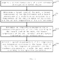
- Fig. 1 is an exemplary flowchart of an air conditioner control method according to one embodiment of the present invention. The steps of the present embodiment may be performed by an air conditioner control device.
- step 101 a current temperature of a chilled water of the unit is acquired at a preset period.
- a target load of the unit, a target temperature of the chilled water and a target temperature of a cooling water are determined according to a temperature of the chilled water set by a user and the current temperature of the chilled water.
- step 102 a difference value ⁇ T between the current temperature of the chilled water and the temperature of the chilled water set by the user is calculated, and the target load of the unit is determined corresponding to the difference value ⁇ T, and the target temperature of the chilled water and target temperature of the cooling water are determined corresponding to the target load of the unit.
- the correspondence relationship between the difference value between the current temperature of the chilled water and the temperature of the chilled water set by the user and the target load of the unit, and the correspondence relationship between the target load of the unit and the target temperature of the chilled water and the target temperature of the cooling water may be obtained through experiments in advance. Therefore, the target load of the unit, the target temperature of the chilled water and the target temperature of the cooling water are determined by using a look-up table.
- the target load of the unit includes an evaporator load and a condenser load.
- step 103 an evaporation parameter and a condensation parameter of the unit are determined according to the target load of the unit, the target temperature of the chilled water and the target temperature of the cooling water.
- the evaporation parameter of the unit comprises an target evaporation pressure and the condensation parameter of the unit comprises a target condensation pressure.
- step 104 operation parameters of the compressor are determined according to the target load of the unit, the evaporation parameter and the condensation parameter, so that the unit can operates according to the operation parameters.
- the air conditioning unit can be efficiently operated by performing optimization control, to ensure high-reliability operation of the whole cold water system.
- a temperature difference between the current temperature of the chilled water and a temperature of the chilled water of the unit acquired in the previous period is further calculated after the target load of the unit is determined, and it is determined whether the temperature difference is greater than the difference value ⁇ T. If the temperature difference is larger than the difference value ⁇ T, the target load of the unit is reduced by a preset magnitude, and the target temperature of the chilled water and target temperature of the cooling water are determined corresponding to the reduced target load of the unit.
- the target load of the unit is increased by a preset magnitude, and the target temperature of the chilled water and the target temperature of the cooling water are determined corresponding to the increased target load of the unit.
- the current temperature of the chilled water of the unit is acquired to be Ta, while the temperature of the chilled water of the unit acquired in the previous operation period is Tb, so that the temperature difference is (Tb-Ta) .
- the target load of the unit is adjusted from Q1 to Q2, wherein Q2 ⁇ Q1.
- the target load of the unit is adjusted from Q1 to Q3, wherein Q3>Q1. Therefore, the overlarge change rate of the temperature of the chilled water can be effectively avoided.
- the target evaporation pressure may be determined based on the evaporator load and the target temperature of the chilled water. And the target condensation pressure is determined according to the condenser load and the target temperature of the cooling water.
- the correlation between the evaporator load, the target temperature of the chilled water, and the target evaporation pressure may be obtained in advance through experiments, and the correlation between the condenser load, the target temperature of the cooling water, and the target condensation pressure may be obtained through experiments, so that the target evaporation pressure and target condensation pressure can be obtained by using a look-up table.
- step 104 the operation parameters of the compressor are determined according to the target load of the unit, the evaporation parameter and the condensation parameter includes:
- the operation frequency of the compressor is obtained according to the target load of the unit, the target evaporation pressure and the target condensation pressure, so that the compressor can operate at the operation frequency.
- the external pressure ratio of the compressor is obtained according to the target evaporation pressure and the target condensation pressure, and the current internal pressure ratio of the compressor is adjusted in conformity with the external pressure ratio of the compressor.
- the correlation between the operation frequency of the compressor and the evaporator load, the condenser load, the evaporation parameter and the condensation parameter may be obtained through experiments in advance. Therefore, the operation frequency of the compressor can be obtained corresponding to the evaporator load, the condenser load, the evaporation parameter and the condensation parameter by using a look-up table.
- the current internal pressure ratio of the compressor can be adjusted in conformity with the external pressure ratio of the compressor by firstly utilizing the target evaporation pressure and the target condensation pressure to obtain the external pressure ratio of the compressor and then adjusting the current internal pressure ratio of the compressor. In this way, coarse adjustment of the internal pressure ratio can be realized.
- a power of the compressor at the moment is W1, i.e., a first power
- the internal pressure ratio is V1.
- the internal pressure ratio is increased by one step to obtain the adj acent internal pressure ratio V2, and the power of the compressor at the moment is W2, i.e., a second power.
- the internal pressure ratio is reduced from V1 by one step to obtain the adjacent internal pressure ratio V3, and the power of the compressor at the moment is W3, i.e., a third power.
- the minimum power value is taken as the operation power of the compressor.
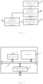
- Fig. 2 is an exemplary block diagram of an air conditioner control device described in the present disclosure. As shown in Fig. 2 , the air conditioner control device includes an acquisition module 21, a first parameter determination module 22, a second parameter determination module 23, and a parameter optimization module 24.
- the acquisition module 21 is configured to acquire a current temperature of a chilled water of a unit at a preset period.
- the first parameter determination module 22 is configured to determine a target load of the unit, a target temperature of the chilled water and a target temperature of a cooling water according to a temperature of the chilled water set by a user and the current temperature of the chilled water.
- the first parameter determination module 22 may be configured to calculate a difference value ⁇ T between the current temperature of the chilled water and the temperature of the chilled water set by a user, determine the target load of the unit according to the difference value ⁇ T, and determine the target temperature of the chilled water and the target temperature of the cooling water corresponding to the target load of the unit.
- the first parameter determination module 22 may be further configured to calculate a temperature difference between the current temperature of the chilled water and a temperature of the chilled water of the unit acquired in the previous period after determining the target load of the unit, and determine whether the temperature difference is greater than the difference value ⁇ T. If the temperature difference is greater than the difference value ⁇ T, the first parameter determination module 22 reduces the target load of the unit by a preset magnitude, and determines the target temperature of the chilled water and the target temperature of the cooling water corresponding to the reduced target load of the unit.
- the first parameter determination module 22 may be further configured to increase the target load of the unit by a preset magnitude if the temperature difference is smaller than the difference value ⁇ T, and determine the target temperature of the chilled water and target temperature of the cooling water corresponding to the increased target load of the unit.
- the target load of the unit may includes an evaporator load and a condenser load.
- the second parameter determination module 23 is configured to determine an evaporation parameter and a condensation parameter of the unit according to the target load of the unit, the target temperature of the chilled water, and the target temperature of the cooling water.
- the evaporation parameter of the unit may comprise an target evaporation pressure and the condensation parameter of the unit comprises a target condensation pressure.
- the second parameter determination module 23 may be configured to determine the target evaporation pressure based on the evaporator load and the target temperature of the chilled water, and determine the target condensation pressure based on the condenser load and the target temperature of the chilled water.
- the parameter optimization module 24 is configured to determine the operation parameters of the compressor based on the target load of the unit, the evaporation parameter and the condensation parameter, so that the unit operates according to the operation parameters.
- the parameter optimization module 24 may be configured to obtain an operation frequency of the compressor according to the target load of the unit, the target evaporation pressure and the target condensation pressure for the compressor to operate at the operation frequency, obtain an external pressure ratio of the compressor according to the target evaporation pressure and the target condensation pressure, and adjust the current internal pressure ratio of the compressor in conformity with the external pressure ratio of the compressor. In this way, coarse adjustment of the internal pressure ratio is realized.
- the parameter optimization module 24 may be further configured to detect a current power W1 of the compressor, i.e., a first power, after adjusting the current internal pressure ratio of the compressor.
- the parameter optimization module 24 decreases the current internal pressure ratio V of the compressor by a preset magnitude and detects the current power W2 of the compressor, i.e., a second power.
- the parameter optimization module 24 increases the current internal pressure ratio V of the compressor by a preset magnitude and detects the current power W3 of the compressor, i.e., a third power.
- the parameter optimization module 24 takes the minimum value among the first power W1, the second power W2 and the third power W3 as the operation power of the compressor, thereby achieving fine adjustment of the internal pressure ratio.
- Fig. 3 is an exemplary block diagram of an air conditioner control device according to another embodiment of the present invention.
- the air conditioner control device includes a memory 31 and a processor 32.
- the memory 31 is used for storing instructions
- the processor 32 is coupled to the memory 31, and the processor 32 is configured to execute the method according to any embodiment in Fig. 1 based on the instructions stored in the memory.
- the air conditioner control device further includes a communication interface 33 for information interaction with other devices.
- the air conditioner control device also comprises a bus 34, and the processor 32, the communication interface 33 and the memory 31 are communicated with each other through the bus 34.
- the memory 31 may comprise high-speed RAM memory, and may also include non-volatile memory, such as at least one disk memory.
- the memory 31 may also be a memory array.
- the storage 31 may also be partitioned into blocks and the blocks may be combined into virtual volumes according to certain rules.
- the processor 32 may be a central processing unit CPU, or may be an application specific integrated circuit ASIC, or one or more integrated circuits configured to implement embodiments of the present invention.
- the present invention also relates to a computer-readable storage medium, in which computer instructions are stored, and when executed by a processor, the instructions implement the method according to any one of the embodiments in Fig. 1 .
- Fig. 4 is an exemplary block diagram of an air conditioner according to one embodiment of the present invention.
- an air conditioner control device 42 is provided in the air conditioner 41.
- the air conditioner control device 42 may be any of the air conditioner control devices described in either of Fig. 2 or Fig. 3 .
- the functional unit modules described above can be implemented as a general purpose Processor, a Programmable Logic Controller (PLC), a Digital Signal Processor (DSP), an Application Specific Integrated Circuit (ASIC), a Field-Programmable Gate Array (FPGA) or other Programmable Logic device, discrete Gate or transistor Logic, discrete hardware components, or any suitable combination thereof for performing the functions described in this disclosure.
- PLC Programmable Logic Controller
- DSP Digital Signal Processor
- ASIC Application Specific Integrated Circuit
- FPGA Field-Programmable Gate Array
- other Programmable Logic device discrete Gate or transistor Logic, discrete hardware components, or any suitable combination thereof for performing the functions described in this disclosure.
- all components of the air conditioning unit can operate in the optimal operation state, so that the high-reliability operation of the air conditioning unit is ensured.
Landscapes
- Engineering & Computer Science (AREA)
- Physics & Mathematics (AREA)
- Mechanical Engineering (AREA)
- Thermal Sciences (AREA)
- General Engineering & Computer Science (AREA)
- Air Conditioning Control Device (AREA)
Claims (7)
- Klimaanlagensteuerungsverfahren, das Folgendes beinhaltet:Erfassen einer aktuellen Temperatur eines gekühlten Wassers einer Einheit mit einer voreingestellten Periode (101) ;Berechnen eines Differenzwerts zwischen der aktuellen Temperatur des gekühlten Wassers und der von dem Benutzer eingestellten Temperatur des gekühlten Wassers;Bestimmen der Ziellast der Einheit entsprechend dem Differenzwert;wobei das Klimaanlagensteuerungsverfahren dadurch gekennzeichnet ist, dass es Folgendes beinhaltet:Bestimmen der Zieltemperatur des gekühlten Wassers und der Zieltemperatur des Kühlwassers entsprechend der Ziellast der Einheit;Bestimmen eines Verdampfungsparameters und eines Verflüssigungsparameters der Einheit gemäß der Ziellast der Einheit, der Zieltemperatur des gekühlten Wassers und der Zieltemperatur des Kühlwassers (103);Bestimmen von Betriebsparametern eines Verdichters gemäß der Ziellast der Einheit, dem Verdampfungsparameter und dem Verflüssigungsparameter für die Einheit für den Betrieb gemäß den Betriebsparametern (104),Berechnen einer Temperaturdifferenz zwischen der aktuellen Temperatur des gekühlten Wassers und einer Temperatur des gekühlten Wassers der Einheit, die in der vorhergehenden Periode erfasst wurde, nach Bestimmen der Ziellast der Einheit;Bestimmen, ob die Temperaturdifferenz größer ist als der Differenzwert;Reduzieren der Ziellast der Einheit um eine voreingestellte Größe unter der Bedingung, dass die Temperaturdifferenz größer ist als der Differenzwert; undBestimmen der Zieltemperatur des gekühlten Wassers und der Zieltemperatur des Kühlwassers entsprechend der reduzierten Ziellast der Einheit;Erhöhen der Ziellast der Einheit um eine voreingestellte Größe unter der Bedingung, dass die Temperaturdifferenz kleiner ist als der Differenzwert; undBestimmen der Zieltemperatur des gekühlten Wassers und der Zieltemperatur des Kühlwassers entsprechend der erhöhten Ziellast der Einheit.
- Klimaanlagensteuerungsverfahren nach Anspruch 1, dadurch gekennzeichnet, dass:die Ziellast der Einheit eine Verdampferlast und eine Verflüssigerlast beinhaltet; undder Verdampfungsparameter der Einheit einen Zielverdampfungsdruck beinhaltet und der Verflüssigungsparameter der Einheit einen Zielverflüssigungsdruck beinhaltet.
- Klimaanlagensteuerungsverfahren nach Anspruch 2, dadurch gekennzeichnet, dass das Bestimmen des Verdampfungsparameters und des Verflüssigungsparameters der Einheit Folgendes beinhaltet:das Bestimmen des Zielverdampfungsdrucks gemäß der Verdampferlast und der Zieltemperatur des gekühlten Wassers; unddas Bestimmen des Zielverflüssigungsdrucks gemäß der Verflüssigerlast und der Zieltemperatur des Kühlwassers; das Bestimmen der Betriebsparameter des Verdichters Folgendes beinhaltet:Erhalten einer Betriebsfrequenz des Verdichters gemäß der Ziellast der Einheit, dem Zielverdampfungsdruck und dem Zielverflüssigungsdruck für den Verdichter für den Betrieb bei der Betriebsfrequenz;Erhalten eines Außendruckverhältnisses des Verdichters gemäß dem Zielverdampfungsdruck und dem Zielverflüssigungsdruck; undEinstellen eines aktuellen Innendruckverhältnisses des Verdichters in Übereinstimmung mit dem Außendruckverhältnis des Verdichters.
- Klimaanlagensteuerungsverfahren nach Anspruch 3, dadurch gekennzeichnet, dass es ferner Folgendes beinhaltet:Ermitteln einer aktuellen Leistung des Verdichters als eine erste Leistung nach Einstellen des aktuellen Innendruckverhältnisses des Verdichters;Reduzieren des aktuellen Innendruckverhältnisses des Verdichters gemäß einer voreingestellten Größe und Ermitteln der aktuellen Leistung des Verdichters als eine zweite Leistung;Erhöhen des aktuellen Innendruckverhältnisses des Verdichters gemäß einer voreingestellten Größe und Ermitteln der aktuellen Leistung des Verdichters als eine dritte Leistung; undNehmen des kleinsten Werts von der ersten Leistung, der zweiten Leistung und der dritten Leistung als die Betriebsleistung des Verdichters.
- Klimaanlagensteuervorrichtung, dadurch gekennzeichnet, dass sie Folgendes beinhaltet:einen Speicher (32), der zum Speichern von Anweisungen konfiguriert ist;einen Prozessor (31), der mit dem Speicher (32) gekoppelt ist und konfiguriert ist, um das Verfahren nach einem der Ansprüche 1 bis 4 auf der Grundlage von durch den Speicher (32) gespeicherten Anweisungen zu implementieren.
- Klimaanlage, dadurch gekennzeichnet, dass sie Folgendes beinhaltet: die Klimaanlagensteuervorrichtung (42) nach Anspruch 5.
- Nichtflüchtiges computerlesbares Speichermedium, dadurch gekennzeichnet, dass das computerlesbare Speichermedium Computeranweisungen speichert, die bei Ausführung durch einen Prozessor das Verfahren nach einem der Ansprüche 1 bis 4 implementieren.
Applications Claiming Priority (2)
| Application Number | Priority Date | Filing Date | Title |
|---|---|---|---|
| CN201810230354.3A CN108444159B (zh) | 2018-03-20 | 2018-03-20 | 空调控制方法和装置、空调 |
| PCT/CN2018/120559 WO2019179177A1 (zh) | 2018-03-20 | 2018-12-12 | 空调控制方法和装置、空调 |
Publications (3)
| Publication Number | Publication Date |
|---|---|
| EP3708930A1 EP3708930A1 (de) | 2020-09-16 |
| EP3708930A4 EP3708930A4 (de) | 2021-03-17 |
| EP3708930B1 true EP3708930B1 (de) | 2023-02-15 |
Family
ID=63195453
Family Applications (1)
| Application Number | Title | Priority Date | Filing Date |
|---|---|---|---|
| EP18910469.8A Active EP3708930B1 (de) | 2018-03-20 | 2018-12-12 | Verfahren und vorrichtung zur steuerung einer klimaanlage und klimaanlage |
Country Status (4)
| Country | Link |
|---|---|
| US (1) | US11187448B2 (de) |
| EP (1) | EP3708930B1 (de) |
| CN (1) | CN108444159B (de) |
| WO (1) | WO2019179177A1 (de) |
Families Citing this family (16)
| Publication number | Priority date | Publication date | Assignee | Title |
|---|---|---|---|---|
| CN108444159B (zh) | 2018-03-20 | 2019-11-08 | 珠海格力电器股份有限公司 | 空调控制方法和装置、空调 |
| CN109556225B (zh) * | 2018-10-31 | 2020-07-17 | 珠海格力电器股份有限公司 | 一种冷却系统的制冷量的控制方法及冷却系统 |
| CN109654688B (zh) * | 2018-12-21 | 2020-08-11 | 珠海格力电器股份有限公司 | 空调机组输出功率的调节方法、系统和空调机组 |
| CN111412624A (zh) * | 2020-03-20 | 2020-07-14 | 青岛海尔空调电子有限公司 | 空调机组及其压缩机频率控制方法 |
| CN111678240B (zh) * | 2020-06-18 | 2021-11-30 | 重庆美的通用制冷设备有限公司 | 空调设备的运行控制方法、空调设备和可读存储介质 |
| CN112797668A (zh) * | 2020-12-31 | 2021-05-14 | 青岛海尔空调电子有限公司 | 水冷热泵机组及其控制方法 |
| CN112902516B (zh) * | 2021-03-08 | 2022-10-21 | 深圳市东洋冷冻设备有限公司 | 冷水机的控制方法、冷水机及存储介质 |
| CN113739358A (zh) * | 2021-08-31 | 2021-12-03 | 广州汇电云联互联网科技有限公司 | 一种冷机节能控制方法及系统 |
| CN114236273A (zh) * | 2021-12-02 | 2022-03-25 | 长沙格力暖通制冷设备有限公司 | 性能检测方法、装置和检测设备 |
| CN114659236B (zh) * | 2022-04-29 | 2023-11-21 | 深圳市英维克信息技术有限公司 | 节能控制方法、装置、设备及存储介质 |
| CN115682572B (zh) * | 2022-11-07 | 2024-08-16 | 珠海格力电器股份有限公司 | 冷冻水机组负荷确定、加卸载控制方法、装置及设备 |
| CN116678075B (zh) * | 2023-06-07 | 2025-07-25 | 香江科技(集团)股份有限公司 | 空调节能控制方法及系统 |
| CN116697630B (zh) * | 2023-06-25 | 2025-09-09 | 西安交通大学 | 基于压缩机流量调节的复叠制冷系统节能优化方法及系统 |
| CN117515786A (zh) * | 2023-10-17 | 2024-02-06 | 福建省数字福建云计算运营有限公司 | 一种制冷机组的加减机控制方法及系统 |
| CN117073128B (zh) * | 2023-10-19 | 2024-01-26 | 深圳市威磁智能科技有限公司 | 一种楼宇温度控制方法、装置和系统 |
| CN118066684A (zh) * | 2024-03-11 | 2024-05-24 | 重庆美的通用制冷设备有限公司 | 空调机组及其控制方法、电子设备、存储介质 |
Family Cites Families (23)
| Publication number | Priority date | Publication date | Assignee | Title |
|---|---|---|---|---|
| JP4690935B2 (ja) * | 2006-05-01 | 2011-06-01 | 三菱重工業株式会社 | 熱源システムおよびその制御方法 |
| CN101363653A (zh) * | 2008-08-22 | 2009-02-11 | 日滔贸易(上海)有限公司 | 中央空调制冷系统的能耗控制方法及装置 |
| JP2010210222A (ja) | 2009-03-12 | 2010-09-24 | Mitsubishi Heavy Ind Ltd | 空気調和機およびその制御方法 |
| CN101968250B (zh) * | 2010-10-13 | 2012-12-05 | 濠信节能科技(上海)有限公司 | 一种冷冻机房节能优化控制系统及方法 |
| JP5514088B2 (ja) | 2010-11-29 | 2014-06-04 | 荏原冷熱システム株式会社 | ターボ冷凍機システム |
| US9915453B2 (en) * | 2012-02-07 | 2018-03-13 | Systecon, Inc. | Indirect evaporative cooling system with supplemental chiller that can be bypassed |
| CN202547019U (zh) | 2012-04-10 | 2012-11-21 | 陈好 | 中央空调节能系统 |
| US9417638B2 (en) * | 2012-12-20 | 2016-08-16 | Automotive Research & Testing Center | Intelligent thermostatic control method and device for an air conditioner blowing cold and hot air |
| JP5984703B2 (ja) | 2013-01-31 | 2016-09-06 | 三菱重工業株式会社 | 熱源システム及び冷却水供給装置の制御装置並びに制御方法 |
| CN104315673B (zh) | 2014-09-16 | 2017-07-11 | 珠海格力电器股份有限公司 | 中央空调模糊控制系统及其控制方法 |
| CN104359195B (zh) * | 2014-12-31 | 2017-03-08 | 江苏联宏自动化系统工程有限公司 | 基于动态响应末端总负荷变化的中央空调冷冻水控制方法 |
| CN106765855B (zh) | 2015-11-20 | 2020-04-10 | 维谛技术有限公司 | 用于空调系统中的控制装置和方法、空调系统 |
| CN105387570B (zh) * | 2015-11-30 | 2018-03-27 | 珠海格力电器股份有限公司 | 冷水机组的执行能力调节方法和装置 |
| CN105444482B (zh) * | 2015-12-11 | 2019-01-18 | 重庆美的通用制冷设备有限公司 | 水冷冷水机组及其节能运行控制方法 |
| CN105423498B (zh) * | 2015-12-21 | 2018-01-23 | 珠海格力电器股份有限公司 | 空调系统的控制方法及空调系统 |
| CN105650808B (zh) * | 2015-12-29 | 2018-11-27 | 深圳市奥宇节能技术股份有限公司 | 冷水机组冷冻水出水温度的调控方法和装置 |
| CN205807750U (zh) * | 2016-06-29 | 2016-12-14 | 启明天工(苏州)控制系统有限公司 | 冷机群控节能控制系统及空调设备 |
| CN106547858A (zh) * | 2016-10-21 | 2017-03-29 | 珠海格力电器股份有限公司 | 一种空调机组大数据分析方法及空调机组 |
| CN107084543A (zh) * | 2017-06-06 | 2017-08-22 | 珠海格力电器股份有限公司 | 水冷冷水机组及其控制方法 |
| CN107192097A (zh) * | 2017-06-06 | 2017-09-22 | 珠海格力电器股份有限公司 | 空调冷冻水系统的控制方法和装置 |
| CN107421062A (zh) | 2017-07-10 | 2017-12-01 | 广东美的暖通设备有限公司 | 空调系统、能需修正方法及计算机可读存储介质 |
| CN107560258A (zh) * | 2017-08-28 | 2018-01-09 | 珠海格力电器股份有限公司 | 冷水机组的性能评估方法及冷水机组 |
| CN108444159B (zh) | 2018-03-20 | 2019-11-08 | 珠海格力电器股份有限公司 | 空调控制方法和装置、空调 |
-
2018
- 2018-03-20 CN CN201810230354.3A patent/CN108444159B/zh active Active
- 2018-12-12 EP EP18910469.8A patent/EP3708930B1/de active Active
- 2018-12-12 US US16/962,557 patent/US11187448B2/en active Active
- 2018-12-12 WO PCT/CN2018/120559 patent/WO2019179177A1/zh not_active Ceased
Also Published As
| Publication number | Publication date |
|---|---|
| EP3708930A1 (de) | 2020-09-16 |
| EP3708930A4 (de) | 2021-03-17 |
| US20200408449A1 (en) | 2020-12-31 |
| CN108444159A (zh) | 2018-08-24 |
| CN108444159B (zh) | 2019-11-08 |
| WO2019179177A1 (zh) | 2019-09-26 |
| US11187448B2 (en) | 2021-11-30 |
Similar Documents
| Publication | Publication Date | Title |
|---|---|---|
| US11187448B2 (en) | Air conditioner control method including determination of a chiller target load | |
| EP3708920B1 (de) | Steuerungsverfahren und -vorrichtung für klimatisierungssystem sowie klimatisierungssystem | |
| CN110949088B (zh) | 汽车电子膨胀阀控制方法和装置以及热泵系统 | |
| US9612601B2 (en) | Systems and methods for adaptive capacity constraint management | |
| CN104246395B (zh) | 制冷循环装置 | |
| CN105953369B (zh) | 一种变频空调控制方法及装置 | |
| CN104990222B (zh) | 空调控制方法及装置 | |
| EP2716989A1 (de) | Temperaturregelungssystem, klimaanlagensystem und steuerverfahren dafür | |
| CN110986276A (zh) | 一种水多联系统防冻控制方法、计算机可读存储介质及空调 | |
| CN105588256B (zh) | 一种多联式空调机组的控制方法及装置 | |
| CN115751514B (zh) | 一种空调系统和空调系统的再热除湿控制方法 | |
| EP3411642B1 (de) | Verfahren zur steuerung eines gebläses eines dampfkompressionssystems in übereinstimmung mit einem variablen temperatursollwert | |
| CN113280463A (zh) | 一种提升室内舒适性的空调控制方法、空调器及存储介质 | |
| EP2839226B1 (de) | Wärmeabgebender wärmetauscher und verfahren zur steuerung eines oder mehrerer lüfter eines wärmeabgebenden wärmetauschers | |
| CN106482295A (zh) | 室内风机控制方法及装置 | |
| JPH05322335A (ja) | 自動冷却停止シーケンス | |
| CN106403175B (zh) | 冷水机组的控制方法及冷水机组 | |
| CN110736272A (zh) | 用于空调补气增焓的控制方法、控制装置及空调 | |
| EP3532779B1 (de) | Verfahren zur steuerung eines kompressors einer wärmepumpe | |
| CN110736214A (zh) | 用于空调除霜的控制方法、控制装置及空调 | |
| CN115871407B (zh) | 热管理系统及其控制方法 | |
| CN115556532A (zh) | 热管理系统的控制方法 | |
| JP2006046839A (ja) | 冷温水搬送システム | |
| CN115930407B (zh) | 空调控制方法和控制装置、空调系统及存储介质 | |
| JP2004294022A (ja) | 空気調和機 |
Legal Events
| Date | Code | Title | Description |
|---|---|---|---|
| STAA | Information on the status of an ep patent application or granted ep patent |
Free format text: STATUS: THE INTERNATIONAL PUBLICATION HAS BEEN MADE |
|
| PUAI | Public reference made under article 153(3) epc to a published international application that has entered the european phase |
Free format text: ORIGINAL CODE: 0009012 |
|
| STAA | Information on the status of an ep patent application or granted ep patent |
Free format text: STATUS: REQUEST FOR EXAMINATION WAS MADE |
|
| 17P | Request for examination filed |
Effective date: 20200608 |
|
| AK | Designated contracting states |
Kind code of ref document: A1 Designated state(s): AL AT BE BG CH CY CZ DE DK EE ES FI FR GB GR HR HU IE IS IT LI LT LU LV MC MK MT NL NO PL PT RO RS SE SI SK SM TR |
|
| AX | Request for extension of the european patent |
Extension state: BA ME |
|
| A4 | Supplementary search report drawn up and despatched |
Effective date: 20210212 |
|
| RIC1 | Information provided on ipc code assigned before grant |
Ipc: F24F 11/00 20180101ALI20210208BHEP Ipc: F25B 49/00 20060101AFI20210208BHEP |
|
| DAV | Request for validation of the european patent (deleted) | ||
| DAX | Request for extension of the european patent (deleted) | ||
| GRAP | Despatch of communication of intention to grant a patent |
Free format text: ORIGINAL CODE: EPIDOSNIGR1 |
|
| STAA | Information on the status of an ep patent application or granted ep patent |
Free format text: STATUS: GRANT OF PATENT IS INTENDED |
|
| INTG | Intention to grant announced |
Effective date: 20220915 |
|
| GRAS | Grant fee paid |
Free format text: ORIGINAL CODE: EPIDOSNIGR3 |
|
| GRAA | (expected) grant |
Free format text: ORIGINAL CODE: 0009210 |
|
| STAA | Information on the status of an ep patent application or granted ep patent |
Free format text: STATUS: THE PATENT HAS BEEN GRANTED |
|
| AK | Designated contracting states |
Kind code of ref document: B1 Designated state(s): AL AT BE BG CH CY CZ DE DK EE ES FI FR GB GR HR HU IE IS IT LI LT LU LV MC MK MT NL NO PL PT RO RS SE SI SK SM TR |
|
| REG | Reference to a national code |
Ref country code: CH Ref legal event code: EP Ref country code: GB Ref legal event code: FG4D |
|
| REG | Reference to a national code |
Ref country code: DE Ref legal event code: R096 Ref document number: 602018046288 Country of ref document: DE |
|
| REG | Reference to a national code |
Ref country code: AT Ref legal event code: REF Ref document number: 1548424 Country of ref document: AT Kind code of ref document: T Effective date: 20230315 Ref country code: IE Ref legal event code: FG4D |
|
| REG | Reference to a national code |
Ref country code: LT Ref legal event code: MG9D |
|
| REG | Reference to a national code |
Ref country code: NL Ref legal event code: MP Effective date: 20230215 |
|
| P01 | Opt-out of the competence of the unified patent court (upc) registered |
Effective date: 20230530 |
|
| REG | Reference to a national code |
Ref country code: AT Ref legal event code: MK05 Ref document number: 1548424 Country of ref document: AT Kind code of ref document: T Effective date: 20230215 |
|
| PG25 | Lapsed in a contracting state [announced via postgrant information from national office to epo] |
Ref country code: RS Free format text: LAPSE BECAUSE OF FAILURE TO SUBMIT A TRANSLATION OF THE DESCRIPTION OR TO PAY THE FEE WITHIN THE PRESCRIBED TIME-LIMIT Effective date: 20230215 Ref country code: PT Free format text: LAPSE BECAUSE OF FAILURE TO SUBMIT A TRANSLATION OF THE DESCRIPTION OR TO PAY THE FEE WITHIN THE PRESCRIBED TIME-LIMIT Effective date: 20230615 Ref country code: NO Free format text: LAPSE BECAUSE OF FAILURE TO SUBMIT A TRANSLATION OF THE DESCRIPTION OR TO PAY THE FEE WITHIN THE PRESCRIBED TIME-LIMIT Effective date: 20230515 Ref country code: NL Free format text: LAPSE BECAUSE OF FAILURE TO SUBMIT A TRANSLATION OF THE DESCRIPTION OR TO PAY THE FEE WITHIN THE PRESCRIBED TIME-LIMIT Effective date: 20230215 Ref country code: LV Free format text: LAPSE BECAUSE OF FAILURE TO SUBMIT A TRANSLATION OF THE DESCRIPTION OR TO PAY THE FEE WITHIN THE PRESCRIBED TIME-LIMIT Effective date: 20230215 Ref country code: LT Free format text: LAPSE BECAUSE OF FAILURE TO SUBMIT A TRANSLATION OF THE DESCRIPTION OR TO PAY THE FEE WITHIN THE PRESCRIBED TIME-LIMIT Effective date: 20230215 Ref country code: HR Free format text: LAPSE BECAUSE OF FAILURE TO SUBMIT A TRANSLATION OF THE DESCRIPTION OR TO PAY THE FEE WITHIN THE PRESCRIBED TIME-LIMIT Effective date: 20230215 Ref country code: ES Free format text: LAPSE BECAUSE OF FAILURE TO SUBMIT A TRANSLATION OF THE DESCRIPTION OR TO PAY THE FEE WITHIN THE PRESCRIBED TIME-LIMIT Effective date: 20230215 Ref country code: AT Free format text: LAPSE BECAUSE OF FAILURE TO SUBMIT A TRANSLATION OF THE DESCRIPTION OR TO PAY THE FEE WITHIN THE PRESCRIBED TIME-LIMIT Effective date: 20230215 |
|
| PG25 | Lapsed in a contracting state [announced via postgrant information from national office to epo] |
Ref country code: SE Free format text: LAPSE BECAUSE OF FAILURE TO SUBMIT A TRANSLATION OF THE DESCRIPTION OR TO PAY THE FEE WITHIN THE PRESCRIBED TIME-LIMIT Effective date: 20230215 Ref country code: PL Free format text: LAPSE BECAUSE OF FAILURE TO SUBMIT A TRANSLATION OF THE DESCRIPTION OR TO PAY THE FEE WITHIN THE PRESCRIBED TIME-LIMIT Effective date: 20230215 Ref country code: IS Free format text: LAPSE BECAUSE OF FAILURE TO SUBMIT A TRANSLATION OF THE DESCRIPTION OR TO PAY THE FEE WITHIN THE PRESCRIBED TIME-LIMIT Effective date: 20230615 Ref country code: GR Free format text: LAPSE BECAUSE OF FAILURE TO SUBMIT A TRANSLATION OF THE DESCRIPTION OR TO PAY THE FEE WITHIN THE PRESCRIBED TIME-LIMIT Effective date: 20230516 Ref country code: FI Free format text: LAPSE BECAUSE OF FAILURE TO SUBMIT A TRANSLATION OF THE DESCRIPTION OR TO PAY THE FEE WITHIN THE PRESCRIBED TIME-LIMIT Effective date: 20230215 |
|
| PG25 | Lapsed in a contracting state [announced via postgrant information from national office to epo] |
Ref country code: SM Free format text: LAPSE BECAUSE OF FAILURE TO SUBMIT A TRANSLATION OF THE DESCRIPTION OR TO PAY THE FEE WITHIN THE PRESCRIBED TIME-LIMIT Effective date: 20230215 Ref country code: RO Free format text: LAPSE BECAUSE OF FAILURE TO SUBMIT A TRANSLATION OF THE DESCRIPTION OR TO PAY THE FEE WITHIN THE PRESCRIBED TIME-LIMIT Effective date: 20230215 Ref country code: EE Free format text: LAPSE BECAUSE OF FAILURE TO SUBMIT A TRANSLATION OF THE DESCRIPTION OR TO PAY THE FEE WITHIN THE PRESCRIBED TIME-LIMIT Effective date: 20230215 Ref country code: DK Free format text: LAPSE BECAUSE OF FAILURE TO SUBMIT A TRANSLATION OF THE DESCRIPTION OR TO PAY THE FEE WITHIN THE PRESCRIBED TIME-LIMIT Effective date: 20230215 Ref country code: CZ Free format text: LAPSE BECAUSE OF FAILURE TO SUBMIT A TRANSLATION OF THE DESCRIPTION OR TO PAY THE FEE WITHIN THE PRESCRIBED TIME-LIMIT Effective date: 20230215 |
|
| REG | Reference to a national code |
Ref country code: DE Ref legal event code: R097 Ref document number: 602018046288 Country of ref document: DE |
|
| PG25 | Lapsed in a contracting state [announced via postgrant information from national office to epo] |
Ref country code: SK Free format text: LAPSE BECAUSE OF FAILURE TO SUBMIT A TRANSLATION OF THE DESCRIPTION OR TO PAY THE FEE WITHIN THE PRESCRIBED TIME-LIMIT Effective date: 20230215 |
|
| PLBE | No opposition filed within time limit |
Free format text: ORIGINAL CODE: 0009261 |
|
| STAA | Information on the status of an ep patent application or granted ep patent |
Free format text: STATUS: NO OPPOSITION FILED WITHIN TIME LIMIT |
|
| 26N | No opposition filed |
Effective date: 20231116 |
|
| PG25 | Lapsed in a contracting state [announced via postgrant information from national office to epo] |
Ref country code: SI Free format text: LAPSE BECAUSE OF FAILURE TO SUBMIT A TRANSLATION OF THE DESCRIPTION OR TO PAY THE FEE WITHIN THE PRESCRIBED TIME-LIMIT Effective date: 20230215 |
|
| REG | Reference to a national code |
Ref country code: CH Ref legal event code: PL |
|
| PG25 | Lapsed in a contracting state [announced via postgrant information from national office to epo] |
Ref country code: LU Free format text: LAPSE BECAUSE OF NON-PAYMENT OF DUE FEES Effective date: 20231212 |
|
| PG25 | Lapsed in a contracting state [announced via postgrant information from national office to epo] |
Ref country code: MC Free format text: LAPSE BECAUSE OF FAILURE TO SUBMIT A TRANSLATION OF THE DESCRIPTION OR TO PAY THE FEE WITHIN THE PRESCRIBED TIME-LIMIT Effective date: 20230215 |
|
| REG | Reference to a national code |
Ref country code: BE Ref legal event code: MM Effective date: 20231231 |
|
| PG25 | Lapsed in a contracting state [announced via postgrant information from national office to epo] |
Ref country code: MC Free format text: LAPSE BECAUSE OF FAILURE TO SUBMIT A TRANSLATION OF THE DESCRIPTION OR TO PAY THE FEE WITHIN THE PRESCRIBED TIME-LIMIT Effective date: 20230215 Ref country code: LU Free format text: LAPSE BECAUSE OF NON-PAYMENT OF DUE FEES Effective date: 20231212 |
|
| REG | Reference to a national code |
Ref country code: IE Ref legal event code: MM4A |
|
| PG25 | Lapsed in a contracting state [announced via postgrant information from national office to epo] |
Ref country code: IE Free format text: LAPSE BECAUSE OF NON-PAYMENT OF DUE FEES Effective date: 20231212 |
|
| PG25 | Lapsed in a contracting state [announced via postgrant information from national office to epo] |
Ref country code: BE Free format text: LAPSE BECAUSE OF NON-PAYMENT OF DUE FEES Effective date: 20231231 |
|
| PG25 | Lapsed in a contracting state [announced via postgrant information from national office to epo] |
Ref country code: CH Free format text: LAPSE BECAUSE OF NON-PAYMENT OF DUE FEES Effective date: 20231231 |
|
| PG25 | Lapsed in a contracting state [announced via postgrant information from national office to epo] |
Ref country code: CH Free format text: LAPSE BECAUSE OF NON-PAYMENT OF DUE FEES Effective date: 20231231 Ref country code: BE Free format text: LAPSE BECAUSE OF NON-PAYMENT OF DUE FEES Effective date: 20231231 Ref country code: IE Free format text: LAPSE BECAUSE OF NON-PAYMENT OF DUE FEES Effective date: 20231212 |
|
| PG25 | Lapsed in a contracting state [announced via postgrant information from national office to epo] |
Ref country code: BG Free format text: LAPSE BECAUSE OF FAILURE TO SUBMIT A TRANSLATION OF THE DESCRIPTION OR TO PAY THE FEE WITHIN THE PRESCRIBED TIME-LIMIT Effective date: 20230215 |
|
| PG25 | Lapsed in a contracting state [announced via postgrant information from national office to epo] |
Ref country code: BG Free format text: LAPSE BECAUSE OF FAILURE TO SUBMIT A TRANSLATION OF THE DESCRIPTION OR TO PAY THE FEE WITHIN THE PRESCRIBED TIME-LIMIT Effective date: 20230215 |
|
| PG25 | Lapsed in a contracting state [announced via postgrant information from national office to epo] |
Ref country code: CY Free format text: LAPSE BECAUSE OF FAILURE TO SUBMIT A TRANSLATION OF THE DESCRIPTION OR TO PAY THE FEE WITHIN THE PRESCRIBED TIME-LIMIT; INVALID AB INITIO Effective date: 20181212 |
|
| PG25 | Lapsed in a contracting state [announced via postgrant information from national office to epo] |
Ref country code: HU Free format text: LAPSE BECAUSE OF FAILURE TO SUBMIT A TRANSLATION OF THE DESCRIPTION OR TO PAY THE FEE WITHIN THE PRESCRIBED TIME-LIMIT; INVALID AB INITIO Effective date: 20181212 |
|
| PG25 | Lapsed in a contracting state [announced via postgrant information from national office to epo] |
Ref country code: TR Free format text: LAPSE BECAUSE OF FAILURE TO SUBMIT A TRANSLATION OF THE DESCRIPTION OR TO PAY THE FEE WITHIN THE PRESCRIBED TIME-LIMIT Effective date: 20230215 |
|
| PGFP | Annual fee paid to national office [announced via postgrant information from national office to epo] |
Ref country code: GB Payment date: 20251111 Year of fee payment: 8 |
|
| PGFP | Annual fee paid to national office [announced via postgrant information from national office to epo] |
Ref country code: FR Payment date: 20251110 Year of fee payment: 8 |
|
| PGFP | Annual fee paid to national office [announced via postgrant information from national office to epo] |
Ref country code: DE Payment date: 20251222 Year of fee payment: 8 |
|
| PGFP | Annual fee paid to national office [announced via postgrant information from national office to epo] |
Ref country code: IT Payment date: 20251231 Year of fee payment: 8 |